1
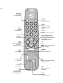
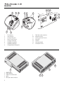
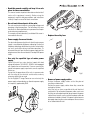
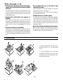
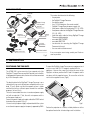
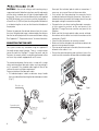
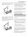
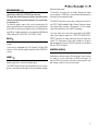
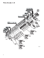
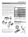
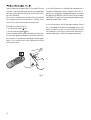
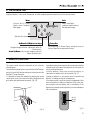
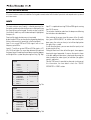
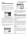
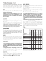
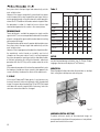
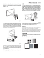
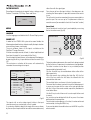
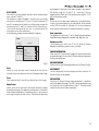
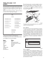
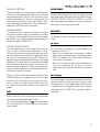
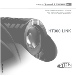
User and Installation Manual
The home theater projector
cod.46.0327.300
HT300 LINK
BACK LIGHT
Turn on the back light
LIGHT
STAND-BY
Switches off to stand-by.
0-9 Keys
Switch on from stand-by
and allow direct source
selection.
SOURCE
Displays the Source
Selection menu.
ESCAPE
Deactivates the On Screen Display.
Not active
in this model.
Up/Down/Left/Right Arrow keys
Navigate through and make adjustments
to the On Screen menus.
Arrow Up/Down activate Quick
menus.
MENU Activates the On Screen
Display menus.
Navigates menu pages.
MENU +
Activates the On Screen Display menus.
Navigates menu pages.
MEMORIES
FREEZE
Freezes a moving
picture.
Activates Memories menu
ZOOM
F1
F1
Select lens zoom
adjustment
INFO
F2
FOCUS
Displays the selected source information
and the projector status.
F2
Select focus
lens adjustment
AUTO
Selects Auto Adjust
(automatic optimisation
of the displayed image).
VCR
Improves the video recorder
signals quality.
ASPECT
Selects image Aspect ratio.
1 INTRODUCTION
Congratulations on your choice of the SIM2 Grand Cinema
HT300 LINK system!
DIGIOPTIC
™ IMAGE PROCESSOR
ON
OFF
PTIC
DIGIO LINK
™
1
2
3
-
UCT
R PROD
S1
LASE
CLAS
1
The HT300 LINK system combines the signal processing
capabilities of the DigiOptic™ Image Processor with the high
fidelity reproduction of the DLP™ technology Projector by linking
the two units via a fibre optic cable.
The DigiOptic™ Image Processor, which should be ideally
located close to the signal sources, supports and processes a
wide range of video signals, transmitting them to the Projector
by means of a fibre optic link cable.
The large number of inputs available (2 Composite Video inputs,
2 S-Video inputs, up to 4 Component or RGB inputs, 2 graphic
RGB inputs, 1 DVI-D input, 1 HDMI™ Input) ensures the system
supports a wide variety of analogue and digital sources: DVD
players, VCRs, satellite and terrestrial receivers, computers,
game consoles, video cameras, etc.
The signal processing capabilities of the Image Processor
ensure optimum reproduction of a broad range of input signals,
from interlaced video to high definition and graphics.
Conversion of interlaced video signals to progressive signals
by means of prestigious DCDi™ technology produces fluid,
natural, images free of flicker and stairstepping artefacts.
Faithful reproduction of signals at higher resolutions (such as
high definition video and graphics) occurs without loss of
information or reduction of image sharpness thanks to the
processor’s high pixel rate signal acquisition capabilities.
All image adjustments can be performed with the remote control
with the aid of the On Screen Display; alternatively, the unit can
be controlled by from a home automation system through the
serial port.
The Projector produces an image using the very latest Texas
Instruments DLP™ technology (1280x720 pixel DMD™HD2+
panel with 12° technology), a proprietary dust-sealed optical
system, a new six-segment colour wheel.
The two units are connected via a three-core fibre optic cable
for transmission of the digital signal from the DigiOptic™ Image
Processor to the Projector and control signals in both directions.
Transmission occurs without interference or attenuation over
distances of up to 500 m.
Moreover, the flexibility and small size of the cable allow the
maximum freedom when installing the system in your home.
SIM2 carries out comprehensive functional testing
in order to guarantee the maximum product quality.
For this reason, when you start using the product
lamp operating hours may already be at between
30 and 60.
In addition to the regular tests, the Quality Control
department performs additional statistical tests at
the time of shipment.
In this case the packing may show signs of having
been opened, and the accumulated lamp operating
hours may be slightly higher than the hours associated with the standard tests.
Adaptation of the input signal resolution to the Projector
resolution occurs without alterations of image quality, in
accordance with an ample choice of aspect ratios, including
several definable by the user.
DLP and DMD are registered trademarks of Texas Instruments.
DCDi is a registered trademark of Faroudja, a division of Genesis Microchip, Inc.
DigiOptic is a registered trademark of SIM 2
HDMI, the HDMI logo and High-Definition Multimedia Interface are trademarks or registered trademarks of HDMI Licensing LLC
2
2 IMPORTANT SAFETY INSTRUCTIONS
ATTENTION:
To reduce the risk of electric shock, disconnect
the power supply cable on the rear panel before
removing the top cover of the projector.
Refer to trained, authorised personnel for
technical assistance.
This symbol indicates the possible electric shock
hazard associated with uninsulated live components
in the interior of the unit.
This symbol indicates the presence of important
instructions regarding use and maintenance of the
product.
The HT300 LINK system consists of two parts connected by a fibre optic cable: the DigiOptic™ Image Processor and the Projector.
In this manual references to the “unit” refer to one of the two units that make up the system.
Prior to switching on the projector please read each chapter of
this manual carefully as this manual provides basic instructions
for using the projector.
The installation of the lamp assembly, preliminary adjustments
and procedures that necessitate the removal of the top cover,
must be carried out by authorised, trained technicians. There
are no user serviceable parts inside. To ensure safe and long
term reliability please use power cables supplied with the
projector. Observe all warnings and cautions.
CLASS 1 LASER PRODUCT
This product complies with fda radiation performance standards, 21 cfr chapter
1 subchapter j.
This product complies with european standard en 60825.
This product is classified as a class 1 laser product and there is no hazardous
radiation with the safety protection.
Danger! Invisible laser radiation when open. avoid direct exposure to beam.
Do not open the covers of the product and never touch the internal parts in order
to avoid exposure to visible or invisible laser radiation.
• Federal Communication Commission (FCC Statement)
This equipment has been tested and found to comply with the limits for a Class B digital device, pursuant to Part 15 of the FCC rules. These limits
are designed to provide reasonable protection against harmful interference when the equipment is used in a commercial environment. This
equipment generates, uses and can radiate radio frequency energy and, if not installed and used in accordance with the instruction manual, may
cause harmful interference to radio communications. However, there is no guarantee that interference will not occur in a particular installation. If
this equipment does cause harmful interference to radio or television reception, which can be determinated by turning the equipment off and on,
the user is encuraged to try to correct the interference by one or more of the following measures:
- Reorient or relocate the receiving antenna
- Increase the separation between the equipment and receiver.
- Connect the equipment into an outlet on a circuit different from that to which the receiver is connected.
- Consult the dealer or an experienced radio/TV technician for help.
• For customers in Canada
This Class B digital apparatus complies with Canadian ICES-003.
• For customers in the United Kingdom
ATTENTION: This apparatus must be earthed
The wires in this mains lead are coloured in accordance with the following code:
Green-and-Yellow:
Earth
Blue:
Neutral
Brown:
Live
As the colours of the wires in the mains lead of this apparatus may not correspond with the coloured markings identifying the terminals in your plug
proceed as follows:
The wire which is coloured green-and-yellow must be connected to the terminal in the plug which is marked by the letter E or by the safety earth
or coloured green or green-and-yellow.
symbol
The wire which is coloured blue must be connected to the terminal which is marked with the letter N or coloured black.
The wire which is coloured brown must be connected to the terminal which is marked with the letter L or coloured red.
3
PROJECTOR
12 11 13
1
2
3
5
9
8
10
1
15
2
3
-
14
T
CL AS
DUC
S1
LA SE
R PR
OD
UC
SER
T
-
SS
3
CLA
PRO
1 LA
2
DIGI
TIC
LIN “
K
1
OP
7
4
6
1
2
3
4
5
6
7
8
Projection lens
Lens shift knob
Cooling air inlet vents
Remote control IR sensor
Cooling air outlet vents
Adjustable carry-handle
Adjustable levelling feet
Ceiling/wall bracket fixing holes
9
10
11
12
13
14
15
Fiber Optic cable connections
Main power switch
Remote control rear IR sensor
Green LED
Red LED
Rear keyboard pad
Fused power socket
HD
...
12
CO
NT
RO
L(
RS
23
2)
3
2
1
DIG
OP
IOP
TIC
10
“ IM
11
DV
I-D
AG
EP
V
RO
H/
SS
OR
B/
G/
ON
7
GR
V
Cr
HV
R/
H/
F
B/
V
Cb
Y
G/
6
HV
H/
Cr
R/
5
B/Cb
Y
G/
HV CO
T
V
EN
ON
MP
/R
GB
S
H/
R/
Cr
B/Cb
Y
G/
1
4
R/
2
3
DC
IN
S-
1
VI DE
12
4
ON/OFF switch
Power connection
Outputs for motorized screens
Inputs
Fiber Optic cable connections
PO
2
VO
UT
W ER
3
O
VI
DE
O
Cr
CL
O/
T
DU
AL
FIB
ER
LIN
K
CT
HV
Cb
Y
OF
1
2
3
4
5
9
8
CE
OU
P RO
ER
AU
L AS
S1
AS
DI
TIC
4
AP
HI
CS
R
GB
5
• Read this manual carefully and keep it in a safe
place for future consultation.
This manual contains important information on how to install
and use this equipment correctly. Before using the
equipment, read the safety prescriptions and instructions
carefully. Keep the manual for future consultation.
• Do not touch internal parts of the units.
The units contain electrical parts carrying high voltages and
operating at high temperatures. Do not remove the cover
from the units, refer to qualified service personnel for all repair
and maintenance requirements.
The warranty will be automatically invalidated if the cover is
removed from the units.
Fig.2
• Replace the safety fuse
• Power supply disconnect device.
The device for disconnecting the units from the mains power
supply is constituted by the power cable plug. Ensure that
the power cable plugs and the electrical mains socket outlets
are easily accessible during installation operations. To
disconnect the units from the electric power supply, pull the
plug to remove it from the socket outlet. Do not pull the power
cable.
• Use only the specified type of mains power
supply.
Connect the units to a mains electrical supply with rated
voltage of between 120-240 VAC, 50/60 Hz and equipped
with a protective earth connection. If you are unsure of the
type of mains power supply in your home, consult a qualified
electrician.
Ensure that the power draw of the units is commensurate
with the rating of the electrical socket outlets and any
extension cables that are used.
For the DigiOptic™ Image Processor use exclusively the
power supply unit provided or an alternative power supply
unit expressly approved by SIM2.
4
250 V
T 3.15A H
2
1
3
Fig.3
• Beware of power supply cables.
Position the power supply cables so that they do not
constitute an obstruction.
Position the power supply cables where they cannot be
reached by children.
Install the units as close as possible to the wall electrical
socket outlet. Do not tread on the power cables, make sure
that they are not tangled or pulled; do not expose the power
cables to heat sources; make sure that the power cables do
not become knotted or kinked. If the power cables become
damaged, stop using the system and request the assistance
of an authorised technician.
Fig.1
5
• Disconnect the apparatus from the mains power
supply in the event of electrical storms and when
not in use.
To avoid damage that could be caused by lightning striking
in the vicinity of your home, disconnect the units in the event
of electrical storms or when the system will remain unused
for prolonged periods.
• Avoid contact with liquids and exposure to
humidity.
Do not use the units near water (sinks, tanks, etc.); do not
place objects containing liquids on top of or near the units
and do not expose them to rain, humidity, dripping water or
spray; do not use water or liquid detergents to clean the
units.
• Prevent the units from overheating.
Do not obstruct ventilation openings. Do not place the units
near heat sources such as heaters, radiators or other devices
that generate heat (including amplifiers). Do not position the
units in confined, poorly ventilated places (bookcase, shelves,
etc.).
• Do not expose the eyes to the intense light
emitted by the lamp.
Never look directly at the lamp through the ventilation
opening when the unit is switched on.
Risk of eyesight impairment. Ensure also that children do
not look directly at the lamp.
• Position the unit on a stable surface.
To avoid serious injury to persons and damage to property,
make sure the units are placed on a level, flat and stable
surface from which they cannot fall, tip over or slide. Pay
special attention if the units are placed on a trolley so that
they can be moved around. Ensure that the units are not
subjected to impact.
• Do not insert objects through the units’ openings.
Make sure that no objects are inserted inside the units. If
this should occur, disconnect the unit from the power supply
immediately and call an authorised technician.
3 UNPACKING
To unpack the projector safely and easily
please follow steps 1 to 6, as per drawing
(Fig. 4).
It is recommended that the carton and
packaging is retained for future use and in
the unlikely event that your projector needs
to be returned for repair.
Fig.4
6
PACKAGE CONTENTS
Projector
Instruction
Manual
The carton should contain the following:
- the projector
- the DigiOptic™ Image Processor
- the remote control
- four 1.5V AAA batteries (for remote control)
- DigiOptic™ Image Processor power supply unit
- three power cables for the projector (EU, UK, USA)
- three power cables for the DigiOptic™ Image Processor
(EU, UK, USA)
- triple fiber optic cable for linking DigiOptic™ Image
Processor and the projector
- one cable HDMI™-HDMI™
- one cable HDMI™-DVI
- two brackets for mounting the DigiOptic™ Image
Processor to the rack.
- the user and installation manual.
I
O
DigiOptic™ Image
Processor power
supply unit
Three-core
fibre optic cable
DIG
IOP
TIC
™
IMA
GE
PR
OC
ES
SO
R
ON
OF
F
DigiOptic™
Image Processor
Support
Remote Control
Cable HDMI™-DVI
1.5 V AAAtype batteries
Power cables
Europe, UK, US (x2)
Cable HDMI™-HDMI™
If any accessories are missing, contact your Dealer as
soon as possible.
Fig.5
4 INSTALLATION
POSITIONING THE TWO UNITS
The HT300 LINK system consists of two separate units (the
DigiOptic™ Image Processor and the Projector), each of which
is equipped with a power cable; the two units are interconnected
by a 20 m fibre optic cable.
The ideal location for the DigiOptic™ Image Processor is on a
cabinet shelf or on a rack (dimensions compatible with a standard 19" rack). Make sure that the support surface is stable
and that the unit has sufficient space around it for ventilation
purposes (at least 3 cm).
The unit is connected to the mains via an external power supply
unit with an output of +7 Vdc; the unit’s main power switch is
on the power supply unit.
Connect the power supply unit output cable to the POWER socket
located on the rear panel (Fig. 2).
Use exclusively the power supply unit provided with the system
or an alternative power supply unit expressly approved by SIM2.
To mount the DigiOptic Image Processor on an equipment rack
use the screws and RH / LH supports supplied with the
appliance. Unscrew the screws that secure the cover to the
DigiOptic unit base, position the RH and LH supports and fix
into place with the supplied screws. To secure the unit to the
rack use the supplied screws (Fig.6).
DIG
IOPT
IC
“ IM
AG
E PR
OC
ES
SO
R
ON
OFF
Fig.6
Position the projector on a stable, suitable platform or utilise
the optional bracket for a fixed ceiling or wall installation.
7
•
•
•
•
CONNECTING THE TWO UNITS
The system can be fully controlled using the supplied IR
(infrared) remote control handset. There is a single remote
control for both the DigiOptic™ Image Processor and the
Projector; the remote control can be directed towards either
unit since they are both equipped with an IR sensor.
The connection between the two units is made with a single
cable containing three fibre optic cables each terminating in
an LC connector. The standard cable length of 20m will be
sufficient for most installation requirements.
During installation of the fibre optic cable:
• The individual optical cables are delicate: always handle
the main cable without touching the individual optical cables
(Fig. 7).
•
•
12
CO
R
3
S2
2)
-
3
2
1
OP
Protective cap
NT
(R
OL
TIC
AL
FIB
ER
LIN
K
3
Position the projector the desired distance from the screen:
the size of the projected image is determined by the distance
from the lens of the projector to the screen and the zoom setting.
See “Appendix C”: Projection distances” for more information.
•
Never pull the individual optical cables or connectors; if
necessary, you may pull the main three-core cable.
Only remove the cap protecting the connector ferrule
immediately before inserting the connector; if the ferrule is
allowed to come into contact with foreign material it may be
damaged, making the connector unusable.
Take particular care when inserting fibre optic connectors
in their respective sockets on the rear panel of the
DigiOptic™ Image Processor and the rear panel of the
Projector.
Make sure that the single optical cables are not switched:
the numbers on the cables must match the numbers on the
connectors (Fig.8-9).
Check that the connectors are correctly inserted.
Make sure that the cable does not constitute an obstacle for
persons moving around the room.
Take care not to create knots in the cable; the minimum radius
of bends in the cable is 2 cm.
Prevent the cable from pulling and mechanical stress: this
could cause the connectors to be pulled out and damaged.
3
CAUTION: In the case of ceiling or wall mounting using a
suspension bracket, follow the instructions carefully and comply
with the safety standards you will find in the box together with
the bracket. If you use a bracket different to the one supplied
by SIM2 Multimedia, you must make sure that the projector is
at least 65 mm (2-9/16 inch) from the ceiling and that the bracket
is not obstructing the air vents on the lid and on the bottom of
the projector.
Fig.8
Ferrule
Separation point
Connector
Fibre
Fig.7
Cable
8
Fig.9
To activate an electric motorised screen a 12 Volt output is
provided at the rear of the DigiOptic™ Image Processor. This
can be connected to a screen interface unit, which can be
supplied by screen manufacturers (Fig. 10).
PFor rear projection the screen must be translucent.
For front projection, we recommend the use of screens with
low gain specifications (i.e. 1.3 to 2). The use of high gain
screens should be avoided due to their limited viewing angle,
which is undesirable for a large audience.
Preferably, use a screen with black, non-reflecting borders,
which will perfectly frame the projected image.
Avoid light shining directly on the screen during projection as
this will reduce contrast and black level detail on the projected
image. For the true cinema experience best results are
achieved with little or no ambient light.
Furniture and other objects with reflecting surfaces, as well as
light coloured walls should be avoided, as they are likely to
interfere with the screen’s characteristics.
CONNECTING THE VIDEO SOURCES
Fig. 10
The output is activated (Voltage: 12 Vdc) when the Projector is
switched on and is de-activated (no Voltage output) when the
projector is in stand-by mode.
Some manufacturers offer screen-masking systems to help frame the projected image and improve picture contrast. These
systems can be connected to output, at the rear of the
DigiOptic™ Image Processor (Fig. 11).
Fig. 11
Connect the cables from the video sources, the serial cable
from the external control unit and the optical fibre cables for
connection to the Projector, to the rear panel of the DigiOptic™
Image Processor.
To obtain the best performance from the HT300 LINK system,
connect the various signal sources using good quality cables
designed for video applications (rated impedance 75 ).
Ensure that:
• the cables are routed in such a way that they do not present
an obstruction to people moving around the room;
• the connectors are inserted carefully to avoid damaging the
pins;
• the cables are not twisted or crushed;
• when disconnecting the cables the connectors are not
violently pulled out of the sockets on the various units.
Video sources (television receivers, VCRs, DVD players, etc.)
often feature several outputs. To obtain the best performance
from your system, carefully choose which output to use.
Generally, the type of signal offering the best picture quality is
DVI-D, followed by RGB, Components, S-Video and Composite
Video, in that order.
However, the HT300 LINK system is equipped with an excellent
Video Decoder and Deinterlacer and therefore even inferior
quality signals will produce high quality results.
9
Table 1 shows the types of signals usually available for the
most common types of video sources and the corresponding
input connectors to use on the DigiOptic™ Image Processor).
Table 1
DigiOptical
Image Processor
Connector
Video signal
source connector
Y (green)
Y
Y
Y
Cr (red)
PR
R-Y
V
Cb (blue)
PB
B-Y
U
VIDEO
These inputs should be connected to a Composite Video signal
(CVBS) by means of a cable with an RCA connector.
The connector on the source is usually yellow and is frequently
labelled VIDEO.
Although other types of signals are preferable (since they allow
better picture quality), this is still the most common type of
output, and nearly all television receivers, video-recorders, DVD
players, video cameras, etc., are equipped with CVBS outputs.
S-VIDEO
These inputs should be connected to an S-Video signal by
means of a cable with a 4-pin mini-DIN type connector.
The corresponding output on the source can be identified by
the wording S-VIDEO or Y/C.
Almost as widespread as Composite Video, S-VIDEO is
preferable because it offers a clearer and sharper picture.
COMPONENT / RGBS
These inputs are composed of three sets of 5 RCA connectors
(5,6,7) and a set of 5 BNC connectors (8).
Each set of connectors is suitable for RGB and Component
signals.
RGB signals can have the following synchronisations:
composite sync on the green signal (RGsB), H+V Composite
Sync, or separate H/V Sync.
10
Connect the R, G, B outputs of the source to the respective R,
G, B inputs of the DigiOptic™ Image Processor (paying attention
not to invert the positions) and any synchronisation signals to
the HV input or the H and V inputs. When connecting the three
sets of RCA connectors use the colours as a guide: connector
R is red, G is green, B is blue, H/HV is white and V is black.
By using a suitable SCART to RCA (or BNC) connector adapter
cable, an RGB video signal from a source equipped with an
SCART connector can be connected to this input.
Component signals are connected to inputs Y, Cr and Cb, taking
care to observe the correspondence with the outputs on the
source.
Since the latter can be labelled in various ways, refer to Table 1
to establish the correspondence between the various signals.
The connector colours can also be of help, as shown in the
table.
Input 5 is dedicated for RGB and YCrCb signals up to 32 KHz
only. In fact, in order to guarantee a high image quality, even
with not so accurate sources, the input signal is elaborated by
specific circuit boards in the DigiOptic™ Image Processor.
The video signal suitable for inputs 6-7-8 can have a scan
frequency of 15KHz (standard video resolution) or 32KHz or
more (progressive scan video, high definition video).
Some sources provide the facility to choose between a
progressive signal or an interlaced signal. Although in general
a progressive signal is higher quality than an interlaced signal,
it is often preferable to perform the deinterlacing operation on
the HT300 LINK system rather than on the source because the
HT300 LINK system is equipped with Faroudja’s sophisticated
directional correlation deinterlacing technology (DCDi™).
Progressive signals usually provide better quality than interlaced
signals, but if the source features both progressive and
deinterlaced signal outputs it is good practice to compare the
quality of the pictures reproduced by the HT300 LINK system
in the two cases: deinterlacing performed by the HT300 LINK
system (thanks to Faroudja DCDi™ technology) is often more
effective than that performed at the source (typically a DVD
player).
RGB GRAPHICS
This input should be connected to an RGB-type video or graphic
signal using a cable with a DB15HD type connector.
The signal source device (typically a personal computer or game
console) must be able to provide separate H/V synchronisation
or composite H+V.
The video or graphic signals that can be connected to this
input can have horizontal scan frequencies (H-sync) of between
32 and 80 kHz and a vertical frequency (V-sync) of between 48
and 100 Hz. Image resolution can vary between 640x480 and
1600x1200 pixels (VGA, SVGA, XGA, SXGA, UXGA).
DVI-D
This input allows you to advantage from the quality of the digital
images .
If your source is equipped with a DVI-D output, YCrCb or RGB
connect it to this input to exploit the quality of the HT300 LINK
system.
HDMI™ 12
With this input it is possible to integrate the optimal quality of a
digital image with a multichannel audio signal.
The HDMI™ (High Definition Multimedia Interface) in fact integrates a multichannel audio signal with the uncompressed high
definition video signal.
The interface also allows the exchange between the video
source and the HT 300 LINK system of control data to optimise
the quality of the projected image.
The HDMI™ input allows connection to video sources that use
the HDCP (High-Bandwidth Digital Content Protection) protocol to protect their contents. This protocol is in fact incorporated in the definition of the HDMI™ technology.
Once the video source has been connected to the HDMI™
input, internal processing by the DIGIOPTIC IMAGE PROCESSOR separates the video information from the audio information. This information is then made available via an optical
digital output with a female TOSLINK connector in accordance
with the S/PDIF standard.
CONTROL (RS232)
The system can be controlled via a personal computer or home
automation systems by means of the serial port: simply connect
this input via a serial cable from an RS232 serial port. On
request, SIM2 will send you a document containing the serial
port settings and the list of main commands.
11
HDMI
Fig.12
12
5 SWITCHING ON AND OFF
The HT300 LINK system consists of the Projector and the
DigiOptic™ Image Processor (which is also the system control
centre). The DigiOptic™ Image Processor sends commands
to the Projector and receives operating status information from
the Projector and function commands from the user. The system
can be controlled from either the remote control (via the infrared
sensors on the DigiOptic™ Image Processor and on the
Projector) or the keypad located on the rear of the Projector.
The two units have separate power supplies however: after
connecting the unit to the electrical mains supply:
1) Set the two power switches to “I”; the DigiOptic™ Image
Processor power switch is located on the external power supply
unit (Fig. 13c), while the Projector switch is on the rear panel
(Fig. 13a).
2) Turn on the DigiOptic™ Image Processor by pressing the
button on the front panel (Fig. 13b).
Significant status signals are given in Table 3.
Table 3
DigiOptic Image
Processor
Status
Green LED
Blue LED
Projector
Green LED
Off
Initialisation
Stand-by
On
Cooling
Optical link not active
Caution
Error
: Off
1
2
3
-
SS
CLA
ER
1 LAS
T
DUC
PRO
Fig.13a
Fig.13a
Blue LED
: Flashing
: On
:
Insignificant
-
If the “No optical link” or “Error” signals are active the system
cannot be operated; if the “Warning” signal is active the system
will operate but it may be unable to read certain input signals
correctly.
SWITCHING ON FROM STAND-BY
I
O
I
O
DIGI
OP
TIC
™
IM
AG
E PR
OC
Fig.13c
ES
SO
R
ON
OF
F
Fig.13c
IM
Switching on the system (Fig.14):
• from the remote control (keys 0-9)
• from the Projector keypad (keys and ).
AG
EP
RO
CE
SS
OR
ON
OF
F
Fig.13b
0
Fig.13b
R
5
0
0
2
T
H
IG
L
I
C
After a few seconds (system initialisation interval), the
DigiOptic™ Image Processor and the Projector assume standby mode.
System status information is provided by two LEDs (green and
blue) on the front panel of the DigiOptic™ Image Processor, a
blue and green LEDS on the rear of the Projector.
Fig.14
13
Typically, the picture will appear after 15-20 seconds. Pressing
a key from 1-9 on the remote control selects the corresponding
input; pressing 0 selects the input active at the time the system
was last switched off.
If the system is switched on very soon after it was last switched
off, the lamp may fail to come on because it is too hot. In this
case just wait a few minutes to allow the lamp to cool.
Switching the system off (Fig.15):
• from the remote control ( key)
• from the Projector keypad ( key).
If you wish to power off the system completely, wait at least one
minute in stand-by before setting the mains power switches on
the units to the “O” position or disconnecting the power supply
cables. This is to allow the fans in the Projector unit sufficient
time to cool the lamp.
0
R
5
0
T
H
0
2
IG
L
I
C
Fig.15
14
In case the Projector unit is shut down (for example due to a
shut down of the projector unit by putting the switch in the “O”
position or by accidentally unplugging the power cord cable)
to re-boost the HT300LINK system it is necessary to shut down
the DigiOptic™ Image Processor and repeat the power-on procedure described in point 1 and 2.
In case the connection with the fiber optics between the two
unit is interrupted (for example by unplagging one or more
cable), to restore the system, it is necessary to turn off the two
units through the main switches and once the connecectin is
restored, repeat steps 1 and 2 of the power-on procedure.
6 KEYBOARD PAD
Eight push buttons, at the rear of the projector, will allow complete operation without the use of the remote control.
Auto
Menu
Activates the On Screen
Display menus. Navigates
Menu pages.
Selects Auto Adjust
(automatic optimisation of
the displayed image).
Switches off to stand-by.
Up/Down/Left/Right arrow keys
Navigate through and make adjustments to the On
Screen menus.
Arrow Up/Down switch on from stand-by and recall
Source Selection menu.
-Focus-Esc
De-activates the On Screen Display and gives access to
the lens Zoom/Focus adjustment functions.
7 REMOTE CONTROL
The remote control transmits commands to the system by
infrared signals.
There are three infrared sensors, one at the front of the Projector,
one at the rear of the Projector and one on the front panel of the
DigiOptic™ Image Processor.
It is possible to control the projector by pointing the remote
control at the screen; the sensor at the front of the projector will
pick up the reflected infrared commands. (Fig. 16).
Avoid placing obstructions between the remote control and the
infrared sensor at the front of the projector; this will impair the
remote control performance.
Insert the batteries, taking care to match the polarity, as
indicated in the battery recess of the remote (Fig. 17).
Change the batteries in the remote control if experiencing
difficulty in sending commands to the projector.
If the remote control is not to be used for a long period of time
remove the batteries. Replace all batteries at the same time;
do not replace one new battery with a used battery. If the
batteries have leaked, carefully wipe the case clean and replace
with new batteries.
-
+
+
-
+
+
-
DVI
C-SYNC
Fig. 16
Four 1.5V
AAA type
batteries
Fig. 17
15
8 ON SCREEN MENU
All system functions can be activated from the keypad or remote control with the aid of a practical and comprehensive system of
on screen menus.
INPUTS
The input selection menu (Inputs) is called by pressing 0 on
the remote control and, when no other menu is displayed, using
the and keys on the keypad. To select an input, scroll the
list with the and keys until the desired input is highlighted,
then press .
Display of the input selection menu is terminated
by pressing the ESC key, or when the time allowed for displaying
the on-screen menu has lapsed (set in the Set-up Menu).
Input 5 can accept RGB and YCrCb signals with a scan
frequency up to 32Khz.
Inputs 6, 7 and 8 can receive RGB and YCrCb signals, at 15
kHz, 32 kHz or higher. The association between the input and
the type of signal is made from the pull-down menu that appears
on the right of the < symbol after pressing the key (Fig. 18b).
Inputs
1
2
3
4
5
6
7
8
9
10
11
12
VIDEO 1
VIDEO 2
S-VIDEO 3
S-VIDEO 4
COMP/RGB 5
COMP/RGB 6
COMP/RGB 7
COMP/RGB 8
GRAPH RGB 9
GRAPH RGB 10
DVI-D 11
HDMI 12
1
2
3
4
5
6
7
8
9
10
11
12
YCrCb 32kHz
RGBS 15kHz
YCrCb
YCrCb 15kHz
YCrCb
Fig. 18a
Inputs
1
2
3
4
5
6
7
8
9
10
11
12
VIDEO 1
VIDEO 2
S-VIDEO 3
S-VIDEO 4
COMP/RGB 5
COMP/RGB 6
COMP/RGB 7
COMP/RGB 8
GRAPH RGB 9
GRAPH RGB 10
DVI-D 11
HDMI 12
1
2
3
4
5
6
7
8
9
10
11
12
YCrCb 32kHz
RGBS15kHz
15kHz
RGBS
YCrCb
RGBS
YCrCb15kHz
15kHz
YCrCb
YCrCb
YCrCb
Fig. 18b
16
Input 11 is capable of receiving YCrCb or RGB signals coming
from DVI-D sources.
The selection should be made from the drop menu following
the indications described above.
After selecting the source signal (by means of the and keys), press MENU+/MENU - to confirm and close the pulldown menu; the value you have just set will be displayed on
the right of the < symbol.
As with the other inputs, you can now select the input just set
by pressing the key.
During the short time it takes to find the signal, a box appears
showing the signal requested. As soon as the signal is shown
in the box additional information is displayed concerning the
video standard (for video signals) or resolution (for graphic
signals), and format.
Fom the SETUP menu it is possible to choose to visualize or not
this information, for more details check the “SOURCE
INFORMATION” in “MENU” section.
MAIN MENU
Image
To access the main menu of the On Screen Display press the
MENU key on the keypad or the MENU+ or MENU- key on the remote control.
The main menu is divided into four windows, PICTURE,
IMAGE, SETUP and MENU, in which the various adjustments are
grouped according to the frequency of use. Use and to select the line corresponding to the adjustment you wish to
make (Fig. 19).
Picture
Brightness
60
Contrast
Colour
Tint
Sharpness
Filter
Cinema Mode
Video Type
Noise Reduction
50
50
50
3
2
Off
Normal
Auto
1
Normal
Anamorphic
Letterbox
Panoramic
Pixel to pixel
User 1
User 2
User 3
Fig. 20b
These submenus are accessed by pressing the key, while
exit and return to the upper level occurs by pressing MENU+/-.
Press ESC on the remote control or keypad to interrupt the
menu display or wait for it to disappear automatically after the
number of seconds set on the SETUP page.
PICTURE
Auto
VCR1
VCR2
Fig. 19
The various menus only offer the relevant adjustments in
accordance with the type of input signal displayed (e.g. certain
typical adjustments for video signals, not necessary for graphic
signals, do not appear on the menus, and vice versa).
Some adjustments (e.g. BRIGHTNESS and CONTRAST) are
associated with a numerical value that can be varied within the
set limits using the keys / . For others (e.g. VIDEO TYPE) you
can choose among three options presented on the same
/ ).
Other adjustments (marked by the < symbol) provide submenus,
which appear as a superimposed window in which the selection
is made with the / keys (Fig. 20). .
This menu features the adjustments related to picture quality.
Adjustments that are not available for a given input do not
appear on the menu. Table 4 summarises the adjustments
available for each input. For a complete overview of the onscreen menus, consult the ‘On screen menu layout’ in the
“Additional Information” section.
BRIGHTNESS
Use this control to adjust the image’s black level without
affecting white areas. Increasing the value will give more detail
in darker parts of the picture. For correct adjustment it may
prove useful to display the signal relative to the grey scale within
which the black level and the level immediately above it must
be separately identifiable. Alternatively use a scene composed
of black objects alongside other dark coloured objects.
CONTRAST
Use this control to adjust the image’s black level without
affecting white areas.
To ensure correct adjustment, it may prove useful to display
the signal relative to the grey scale, within which the white level
and the level immediately below it must be separately
identifiable. Alternatively use a scene composed of well-lit white
objects surrounded by light coloured objects with lower level
lighting.
Image
Aspect
Colour Temperature
Gamma Correction
Overscan
Position
Y/C Delay
Aspect
Colour Temperature
Gamma Correction
Overscan
Position
Y/C Delay
1
1
Fig. 20a
COLOR
This control (also called Saturation) increases or decreases
17
CINEMA MODE
In AUTO the deinterlacer recognises if the video signal source
is a movie film (obtained from a Telecine device with 3:2 or 2:2
pull-down) and applies a deinterlace algorithm optimised for this
type of signal.
If the video signal source is not identified as a film, or if you
select NO the deinterlacer applies a Motion compensated
algorithm optimised for video camera signals.
VIDEO TYPE
Activates a filter to improve stability of pictures from video
recorders or DVD players. To toggle between NORMAL, VCR1
mode and VCR2 mode press
on the remote control.
18
RGB Grafico
DVI-D
HDMI™
FILTER
This allows you to select the mode in which the input signal
is processed. Selecting the most appropriate value for a given
input signal ensures the best horizontal and vertical definition
and makes the picture sharper.
Inputs
Colour
-
-
-
Tint
-
-
-
Adjustments
YCrCb
SHARPNESS MODE
This allows you to select the type of processing associated
with sharpness adjustment. In the case of a progressive or
interlaced video signal VIDEO mode is advisable; with PC graphic
signals use GRAPHIC MODE.
Table 4
RGBS
SHARPNESS
Use this adjustment to increase and decrease the level of
picture detail.
When the sharpness value is reduced the image details
appear less pronounced, while increasing the value raises
image definition, making the outline of objects sharper.
Note that an excessively high value may result in a ‘noisy’ picture
and the edges of objects may be unnaturally defined.
RGBS 15kHz
YCrCb 15kHz
TINT
Controls the purity of the colours. Basically determines the
red-green ratio of the picture.
Reducing the value will boost the red contents of the picture,
increasing the value will boost the green tones. For this
adjustment use skin tones or a test pattern image with colour
bars as a reference.
NOISE REDUCTION
This adjustments allows to choose the filter value for noise
reduction purposes.
As soon as this option is selected on the menu, the image is
divided in two parts.
In the left side the image is not altered by the filter, in the right
part the filter is activated.
This allows you to compare the effect of the filter.
It is possible to deactivated the filter (NOT ACTIVE), to use the
automatic adjustments (AUTO) or to manually select (MANUAL)
the value suitable for the image with the VALUE adjustment.
In case of using the VALUE adjustement, it is enoght to select to
cursor below and set the value with the / keys of the remote
control.
Associated to the NOISE REDUCTION there is the possibility to use the
specific function (FLESH TONE CORRECTION) to make skin tone more
natural. Often the use of noise reduction filter slightly degrades
the image in those areas where skin tones are visible. With the
use of this function it is possible to maintain an excellent image
quality throughout the entire projected image.
Video
S-Video
the picture colour intensity. When set to zero, colour images
will be shown in black and white. Increasing the value, try to
find the point at which the colours look natural: suitable
references include skin tones and grass in landscape shots.
Brightness
Contrast
Sharpness
Sharpness Mode
Filter
-
-
-
-
-
Cinema Mode
-
-
-
-
Video Type
-
-
-
-
Noise reduction
-
-
-
-
Flesh tone correction
-
-
-
-
Present only if the Video Standard is NTSC
IMAGE
This menu features adjustments relating to picture position,
aspect ratio, etc.
ASPECT
This adjustment allows you to change the dimensions and
aspect ratio (relationship between width and height) of the
displayed image. There are five preset aspects available and
three personalised aspects (with user-settable parameters). You
can select a different aspect for each source: the selected
aspect ratio will be automatically called the next time the relative source is called.
You can also select the required aspect ratio by repeatedly
pressing the
key, or by pressing
and a numerical key
(1...8).
The following aspects are available.
NORMAL: projects the image occupying the full height of the
screen while maintaining the aspect ratio of the input signal.
When the input signal aspect ratio is 4:3 black vertical bands
are displayed on the right and left of the picture.
ANAMORPHIC: allows a 16:9 picture to be displayed correctly.
LETTERBOX: serves to display 4:3 letterbox image (with source
signal having black bands above and below the picture) so
that it fills the 16:9 screen and maintains the correct aspect
ratio.
PANORAMIC: this aspect stretches the 4:3 image, slightly
cropping the upper and lower parts.
Panoramic is ideal for displaying a 4:3 image on the 16:9 screen
of the Display.
PIXEL TO PIXEL: this aspect displays the image as it is input without
adapting it to the screen.
The image is projected in the centre of the screen and if its
horizontal and/or vertical dimensions are smaller than the
display, it is bounded by vertical and/or horizontal black bands.
USER 1, 2, 3: When none of the preset formulas are suitable, the
User formulas are available, with the facility for continuous
horizontal and vertical adjustment of picture size.
SCREEN CONTROL
If an appropriate screen-masking interface is connected to the
12V output socket it is possible, for each aspect chosen, to reframe the screen to a variety of aspect ratios and screen sizes
(please refer to the screen manufacturer’s manual).
COLOR TEMPERATURE
Changes the colour balance of the image.
Colours can be adjusted towards the red end of the spectrum
(low colour temperature values - expressed in degrees Kelvin)
or the blue end (high values).
Colour temperature can be selected with three preset values:
HIGH (corresponding to approx. 9000 degrees Kelvin), MEDIUM
(approx. 8000 degrees Kelvin), LOW (approx. 6500 degrees
Kelvin) and one PERSONAL setting controlled by the user with
separate adjustments for RED, GREEN and BLUE.
In the personale color adjustment for all three colors it is possible
to set an Offset value and Gain.
The Offset adjustments have an impact of the low IRE values,
while the Gain adjustments impact of the higher IRE values.
Generally, the HIGH value is more suitable for displaying graphic
images, MEDIUM and LOW for video images.
These adjustments are reserved for expert users since there is
a risk of obtaining results that impair projected image quality.
GAMMA CORRECTION
Determines the system’s response to the grey scale,
emphasising or attenuating the different grades of brightness
(blacks, dark, medium, light grey, whites) in the projected
image.
The GRAPHICS setting is more suitable for computer images,
while the FILM and VIDEO settings are more suitable for video
images.
OVERSCAN
Remove noise around image. Some sources can produce a
picture with noise along edges, thanks to the overscan function
it is possible to drop such imperfections outside the projected
area. The overscan value can be included between 0 (no
overscan) and 32 (maximum value). The image maintains in
any case the aspect.
POSITION
Use this adjustment to position the image vertically and
horizontally. Determines the aspect ratio of the projected image.
These parameters do not normally require adjustment because
19
FREQUENCY/PHASE
These adjustments, available for progressive signals and for
signals from PC, ensure correspondence between the number
of pixels making up the signal and the number of pixels making
up the projected image.
These parameters do not normally require adjustment because
the system checks the input signal and automatically sets the
most suitable values.
However, if the image appears disturbed (loss of position within
the equidistant vertical bands or instability and lack of
sharpness on the narrow vertical lines) it may help to prompt
the system to repeat the input signal analysis and determination
of the best parameters by calling the automatic adjustment
procedure with the AUTO key on the remote control or on the
keypad.
If the automatic procedure fails to have the required effect, enter
the frequency and phase values manually and approach the
screen sufficiently to observe the effects of the adjustments.
Table 5
Position
DVI-D
HDMI™
RGB Grafico
YCrCb
RGBS
Adjustments
RGBS 15kHz
YCrCb 15kHz
Inputs
Video
S-Video
the system checks the input signal and automatically sets the
most suitable values.
However, if the image is not perfectly centralised it may prove
useful to request the system to repeat the input signal analysis
and image positioning, calling the automatic control procedure from the AUTO button on the remote control or keypad. When
this procedure is called it is helpful to have a white or light
coloured background on the screen in the current picture.
-
Aspect
Frequency
-
-
-
Phase
-
-
-
Colour Temperature
Gamma Correction
Overscan
Y/C Delay
-
-
-
-
SETUP
The setup menu contains less frequently used adjustments that
may be required during installation (e.g. On Screen Display
language selection or the display of Test Patterns).
ORIENTATION
Select the option that best describes the installation i.e. desktop
front, ceiling front, desktop rear and ceiling rear.
Y / C DELAY
In the case of Video and S-Video signals, it may be necessary
to correct horizontal colour misalignment within the projected
image. For a given video standard (e.g. PAL or NTSC) the stored
value does not normally require further fine-tuning, unless the
source or connection cable has changed.
1
2
3
-
CT
PRODU
1 LASER
CLASS
Fig. 21
HORIZONTAL/VERTICAL KEYSTONE
To obtain maximum quality of the projected image, we
recommend the installation of the projector on a level platform
parallel and central to the screen.
20
LENS
The Zoom adjustment impacts on the motorized zoom lens
allowing to increase or decrease the dimension of the projected
image. The Focus adjustment impacts on the motorized lens
focus, allowing to obtain the highest definition on the projected
image, an accurate focus setting should allow the viewer to
distinguish each pixel that create the image one from another.
ZO
O
M
Adjust the feet underneath to obtain a level position, lining up
the base of the projected image to the base of the projection
screen (Fig. 22).
ZOOM
ZO
OM
1
2
3
-
UCT
PROD
1 LASER
FOCUS
ZO
OM
ZO
O
M
CLASS
FOCUS
FOCUS
FOCUS
1
2
3
-
PR
ODUCT
1 LASER
CLASS
Fig. 22
If the projected images needs to be centred horizontally, the
manual lens shift adjustment allows the projected image to be
moved vertically, up or down, in relation to the centre of the
screen; the maximum adjustment being equal to half the height
of the image in either direction (Fig. 23).
Fig. 24
In the initial phase of installation the configurable keys (F1, F2)
serve as optical zoom and optical focus (Fig.24).
POWER ON
If active (AUTO) allows to power up the system directly from the
power feeder, once the initializing phase is completed.
If not active (STAND-BY) once the initializing phase is completed
the system remains in a stand-by mode waiting to receive the
power on command from the remote control or the key pad.
TEST PATTERNS
Displays a series of five test patterns, useful for the installation
of the projector.
Press and keys to browse pattern.
1
2
3
-
CT
PRODU
1 LASER
CLASS
Fig. 23
In the event you are unable to centre the image within the screen
area, tilt the projector until the image is correctly positioned.
Any keystone error can be removed by the Keystone adjustment
in the Set up menu.
The keystone adjustement helps to compensate possible
horizontal tilts of the projector.
21
FACTORY DEFAULTS
Reconfigures the projector to original factory settings except
Position, Orientation, Y/C Delay, Zoom and Focus.
Confirm?
No
Yes
Insert text
You will be able to insert text easily and rapidly by accessing
the text insertion menu (fig. 26)
MENU
LANGUAGE
Lists the languages available for the On Screen Display menus.
SOURCE LIST
In order for the HT300 LINK system to be more flexible, the
following described functions allow to modify the input selection
menu making it more user friendly.
The main window shows all the inputs available on the
DigiOptic™ Image Processor.
If one or more inputs are not utilized, it is often helpful to blank
them from the input list (accessed with the 0 key).
Once the input has been chosen, in the drop menu that appears
by pressing the key, it is possible to activate the source (Fig.
25).
The exclusion or activation of the source will automatically
renumber the remaining active inputs.
Source list/Edit source name
1
2
3
4
5
6
7
8
9
10
11
12
VIDEO 1
VIDEO 2
S-VIDEO 3
S-VIDEO 4
COMPONENT / RGBS
COMPONENT / RGBS
COMPONENT / RGBS
COMPONENT / RGBS
GRAPHICS RGB 9
GRAPHICS RGB 10
DVI-D 11
HDMI 12
5
6
7
8
VIDEO 1
VIDEO 2
S-VIDEO 3 Yes
ACTIVE
S-VIDEO 4
NAME
COMP RGB 5
COMP RGB 6
COMP RGB 7
COMP RGB 8
GRAPH RGB 9
GRAPH RGB 10
DVI-D 11
HDMI 12
No
Fig.25
The inputs with an active video signal (visible in the input
selection menu) are marked with a check symbol.
It can be also helpful to identify the input with a name chosen
by the user (for example with the name of the connected source)
22
rather than with the signal type.
Once chosen to have the input visible, in the drop menu, by
selecting the Name option it is possible to rename the source
in use.
This will make it easier to remember the source connected to a
specific input. You can use up to 12 alphanumeric letters to
name the source (for more details check the “Insert text” section)
Edit source name
___________
Cancel
-
Confirm
+
()?@
1
ABC
2
DEF
3
GHI
4
JKL
5
MNO
6
PQRS
7
TUV
8
WXYZ
9
0
Fig.26
The text insertion mode remains the same if text is being inserted
for the first time or if a previously inserted name is being edited.
The letter insertion can be done in any available position
(represented by horizontal lines).
Use the and keys to move between letters either left or
right respectively.
Press the numeric key matching the letter (fig. 26), the first
click of the key selects the first letter, the second click the
second letter and so on.
The available letters are shown in the text insertion menu.
Once one letter has been inserted, to insert the following one it
is necessary to move with the cursor in the next right position
with the key of the remote control, repeat this procedure to
insert other letters.
Use the key to switch from small case to capital letters and
viceversa.
Any mistake can be deleted with the key once it has been
positioned on the wrong letter.
Once the text insertion process is finished, it can be confirmed
and saved by clicking the MENU+ key.
If you want to delete the modifications use the MENU- key of the
remote control.
F1/F2 KEYS
This allows to assign different functions to the remote control
keys, named F1 and F2.
The window is made of 6 options, once for each line and by
two columns showing the F1-F2 keys. The choice between F1
and F2 is made by the and keys of the remote control; the
function given to F1 and F2 is chosen with the and keys.
The function delivered by the key is memorized by the
intersection on the line and column.
In the following window are described the 6 options
be enlarged is selected in Pan mode (symbol in the centre of
the picture) using the and , arrow keys. You can
toggle between Zoom and Pan mode by pressing the F1/F2
key on the remote control.
Blank
Blanks the active video signal producing a completely black
screen. Once pressed the key an indication of a few seconds
on the OSD will confirm its activation. A click of any other key
of the remote control allows to restore the previous settings.
Color temperature
The following click of the key (F1 or F2) allows to choose between
the different color temperatures available. High, Mid, Low, User.
Menu
Language
English
Source list
F1/F2 keys
Source info
Zoom
OSD Backgroung
Focus
OSD Position
Magnification
OSD Timeout Blank
Gamma correction
The following click of the key (F1 or F2) allows to choose
between the different gamma curves available.
F1 F2
SOURCE INFORMATION
When active (YES) each source change will show the information
related to the signal. If not active (NO) there will be no information
on the selected source.
Colour temperature
Gamma correction
Fig.27
Zoom
Allows to access the optic zoom, where the and keys
allow to increase or decrease the size of the projected image.
Focus
Once selected, the and keys allow to focus the image.
Magnification
Allows you to select the area to be viewed and then magnify
the projected image. The degree of enlargement is selected in
Zoom mode (identified by a magnifying glass in the centre of
the image) using the and keys. The area of the picture to
OSD BACKGROUND
Determines the type of background for the On Screen Display.
OSD TIMEOUT
Use this adjustment to set the display time after which the On
Screen Display will disappear.
OSD POSITION
Allows the On Screen Display to be positioned in a particular
area of the projected image. The OSD can be positioned using
the arrow keys for fine adjustments or keys 1...9 on the remote
control to select one of 9 preset positions.
23
MEMORIES
The main parameters of the image may be saved in distinct
groups of values (known as ‘Memories’); these parameters can
subsequently be applied all together by way of a single command.
There are 3 distinct Memories (Memory 1, Memory 2, Memory
3) for each of the 25 signal types managed:
Some of these parameters may not be available for certain inputs or certain input signals, as indicated in Tables 4 and 5.
The menu page for the Memories management functions is
key on the remote control or the
activated by pressing the
key on the keypad (Fig.28).
1 VIDEO
2 VIDEO
3 S-VIDEO
20
4 S-VIDEO
05
ZOO
5 COMP/RGB(YCrCb 32KHz)
5 COMP/RGB(RGB 32KHz)
M
E
5 COMP/RGB(RGB 15KHz)
F1
5 COMP/RGB(YCrCb 15KHz)
6 COMP/RGB(YCrCb 15KHz)
6 COMP/RGB(RGB 15KHz)
6 COMP/RGB(YCrCb)
6 COMP/RGB(RGB)
7 COMP/RGB(YCrCb 15KHz)
7 COMP/RGB(RGB 15KHz)
7 COMP/RGB(YCrCb)
7 COMP/RGB(RGB)
8 COMP/RGB(YCrCb 15KHz)
8 COMP/RGB(RGB 15KHz)
8 COMP/RGB(YCrCb)
8 COMP/RGB(RGB)
9 GRAPHICS RGB
10 GRAPHICS RGB
11 DVI-D (RGB)
11 DVI-D (YCrCb)
12 HDMI
making a total of 75 different available Memories.
The image parameters that can be saved/recalled by the Memories management system are the following:
Image
BRIGHTNESS
CONTRAST
COLOR
TINT
SHARPNESS
FILTER
SHARPNESS MODE
VIDEO TYPE
NOISE REDUCTION
24
Picture
ASPECT
COLOR TEMP. GAIN (R/G/B)
COLOR TEMP. GAIN OFFSET (R/G/B)
COLOR TEMP.
OVERSCAN
GAMMA
Fig.28
The operations that can be performed on each memory selected are described here below.
SAVE A MEMORY
To save the current values of the image parameters in Memory
1, use the and keys to move to line ‘1’ and then open the
pull-down menu by pressing the key (Fig.29). Then select
the option ‘Save current settings’. To confirm that the operation
has been completed successfully, the message ‘Current settings saved in Memory 1’ is displayed at the bottom of the screen
and the letter ‘S’ appears to the left of the memory name. The
same procedure is used to save parameters in Memories 2
and 3.
Memories
0 Auto
1
S Save current settings
2
I
Save initial settings
3
S MEMORIA
Rename 1
Fig.29
RECALL A MEMORY
To recall a Memory, select the desired line and press . The
parameters saved in the selected Memory will be applied to
the image displayed and a message will appear to confirm the
operation ‘Memory 1 recalled’. The Memory recalled will be
associated with the source and signal type, and will be automatically recalled every time that particular source and signal
type combination is selected.
SAVE DEFAULT SETTINGS
To restore the original values to a previously modified Memory,
select the line corresponding to the Memory in question and
open the pull-down menu ( key). Then select the line ‘Initial
settings saved in Memory 1’. To confirm that the operation has
been completed successfully, the message ‘Memory 1 initialised’ is displayed at the bottom of the screen and the letter ‘I’
appears to the left of the name of the memory.
RENAME A MEMORY
It is possible to assign a name to each Memory. To assign a
name (with a maximum length of 12 alphanumeric characters)
to a Memory, select the option ‘Rename’ from the corresponding pull-down menu. Enter the text following the procedure indicated in paragraph “SOURCE LIST”.
QUICK MENUS
The quick menus provide access to the main adjustments that
affect image quality, without calling the main On Screen menus.
BRIGHTNESS, CONTRAST, COLOUR, TINT, SHARPNESS and FILTER
adjustments appear at the bottom of the screen one after the
other when the and keys are pressed .
MESSAGES
The following messages may appear during operation of the
system:
No signal
RESTORE CURRENT SETTINGS
On entering the ‘Memories’ menu, a copy of the current settings is saved in a temporary menu (labelled with 0 - AUTO).
Once one or more memories have been recalled, you can restore the settings that were effective at the moment the Memories menu was accessed by selecting 0 - AUTO. However, this
operation must be completed before the ‘Memories’ menu page
disappears (30 seconds after the last operation commanded
from the remote control or the keypad). The next time it appears, the temporary memory will contain new information that
takes into account any Memories selected the penultimate time
the ‘Memories’ page was accessed.
Memory 0 (- AUTO) can be used even when you do not wish to
enable the Memories management function for the signal
currently in use. Once Memory 0 has been selected, when a
source is chosen, the settings that were effective at the time
the Memory was previously recalled will be automatically
applied.
INFO
The system does not recognise any signal applied to the
selected input. In this case:
• Make sure the selected input is connected to a video or
graphic signal and that that source is functioning correctly.
• Check the condition of the cables used to connect the
system to the various sources.
• Make sure the video or graphic signals supplied by the
source are compatible with the system’s technical
specifications and, in particular, with those of the selected
input.
Out of Range
This message appears when either the resolution or the vertical/
horizontal frequency of the input signal exceeds system
specifications (e.g. a QXGA graphic signal) or when an input
is supplied with an incompatible signal (after setting the
components input to YCrCb 15kHz a progressive signal is
connected).
Displays the current status of the projector and information
concerning the projected video/graphic signal.
This function is displayed on pressing
on the remote control
(or, in the absence of the On Screen Display, the key on the
remote control).
25
9 CLEANING AND MAINTENANCE
The Projector and DigiOptic™ Image Processor do not require
internal cleaning. There are no user serviceable parts inside
the projector. Please refer all service requirements to qualified
personnel.
Cleaning the lens:
The lens may be cleaned with a very soft, non-abrasive small
brush, in order to remove dust particles. Alternatively, use a
soft dry cleaning cloth (of the type used for camera lens
cleaning) to remove fingerprints and grease marks.
Cleaning the projector’s cover:
Use a soft slightly damp cloth. Do not use abrasive cleaners,
solvents or other harsh chemicals, as this will damage the finish
of the cover. Avoid direct cleaning of the rear panel’s screenprinting.
10 TROUBLESHOOTING GUIDE
No power (Green and red LED are OFF)
- Check the power switch at the rear: it must be in position I.
- Check if the power cable has been connected correctly to a
working socket.
- Check the power socket fuse, at the rear of the projector.
- Replace the fuse on the mains socket with an identical type
(T 3.15A H) (Fig. 2).
- Should the problem persist, seek authorised technical
assistance.
The lamp is not coming on
- Allow a few minutes pause between switching off and turning
on again (from stand-by). This will allow the lamp to cool down
sufficiently.
- If the lamp doesn’t come on – even though the projector has
had sufficient time to cool down – seek technical assistance
from your nearest Dealer.
No image
- Check that the selected input is actually connected to a active
video or graphic signal.
- Check that the above source actually works.
- Verify compatibility of video/graphic signals with the technical
specifications of the projector.
26
- Check the integrity of cables used to connect various sources.
- Check the cooling air inlets or air outlets on the units are not
obstructed and the room temperature is below 35°C (95°F).
Image is disturbed, unstable or noisy
- Verify compatibility of video/graphic signals with the technical
specifications of the projector.
- Check the integrity of cables connecting projector to various
sources.
- If the signal source is a terrestrial broadcast (via a VCR) check
that the receiving channel has been correctly tuned in and
that the aerial system is in good working order.
- Should the problem be present with a signal coming from a
video-recorder, ensure that the videotape is an Original “first
generation” copy and in good condition.
- Adjust the VCR’s tracking control for optimum picture performance. Ensure the VCR mode is active in the Picture menu.
Incomplete image along borders (vertical and horizontal)
- Compare compatibility of video/graphic signals and technical specifications of your projector.
- Press A on your remote control or AUTO on keypad to execute
automatic adjustments.
- Adjust the horizontal and vertical position of projected image
by selecting POSITION on the IMAGE ADJUSTMENTS menu.
- Adjust the width and height of image, selecting ASPECT in the
IMAGE ADJUSTMENTS menu.
- Adjust the Overscan value in the IMAGE/OVERSCAN menu.
Image too dark, too pale or unnaturally coloured
- Verify compatibility of video/graphic signals with technical
specifications of your projector.
- Go to PICTURE menu, select and regulate any of the following,
accordingly: CONTRAST, BRIGHTNESS, COLOR, and TINT.
- If necessary, reset the COLOR TEMPERATURE and GAMMA
CORRECTION (found on the IMAGE ADJUSTMENTS / ADVANCED
SETTINGS menu).
Graphic image with poor quality vertical detail
Video Image showing colour misalignment on vertical
details
- Verify compatibility of video/graphic signals with technical
specifications of your projector.
- Adjust Y/C DELAY settings in the IMAGE ADJUSTMENTS /
ADVANCED SETTINGS to reduce colour misalignment. For
best results use an external colour bar test pattern source.
Remote control does not work
- Check the batteries and for correct polarity.
- Ensure that the area between the infrared sensor (front of
projector) and the remote control is free of obstruction.
- Ensure that infrared sensors (front and rear of projector) are
not exposed to intense light levels.
- Verify compatibility of video/graphic signals with technical
specifications of your projector.
- Press A on your remote control or AUTO on keypad to
execute automatic adjustments.
- Adjust FREQUENCY and PHASE parameters, found in the
IMAGE ADJUSTMENTS menu, to optimise vertical detail of the
projected image.
11 OPTIONAL ACCESSORIES
You can purchase the following optional accessories at your
Dealer:
- Wall/Ceiling Bracket Kit.
CAUTION: for ceiling/wall installation, by means of
suspension bracket, carefully follow the
instructions and safety instructions recommended
by the Manufacturer in the bracket’s literature.
Use only original, or SIM2 Multimedia approved,
accessories.
27
12 ADDITIONAL INFORMATION
A TECHNICAL SPECIFICATION
GENERAL
PROJECTOR
Supply:
from 120 to 240 Vac, -10% +6%
tolerance
Frequency:
from 48 to 62 Hz
Consumption:
180 W max
Fuse:
T 3.15A H, 5 x 20 mm
Dimensions of projector:
352 mm x 174 mm x 318 mm
(LxHxD)
13”-7/8 x 6”-7/8 x 12”-1/2 (LxHxD)
OPTICAL
Projection system:
optical engine based on 1 DMD™
HD2+
chip, sealed housing, dusty
proof
DMD™ panel:
resolution 1280x720 pixel
Brightness uniformity:
10% above or below the average
Contrast ratio:
> 2800:1 (full On / full Off)
Weight of projector:
5.0 kg (11 lbs)
Projection lens:
zoom, 12 elements AR multilayer
coating, motorized focus and zoom,
manual elevation
Packaging and
510 mm x 440 mm x 450 mm
(LxHxD)
Aperture f#:
2.7 (zoom max) - 3.3 (zoom min)
ENVIROMENTAL
Picture size:
50-250 inches (diagonal measure)
Operation temperature:
0 to 35°C (32° to 95°F)
Aspect ratio:
4/3 and 16/9
Transportation temp.:
-10 to 55°C (14° to 131°F)
Throw ratio:
1.8:1 - 2.5:1
Storage temperature:
-10 to 55°C (14° to 131°F)
Humidity:
10% to 90% relative humidity noncondensing
Safety:
EN 60950, UL 60950
Transportability:
desktop equipment
Electromagnetic
compatibility:
EN 55022 Class B
EN 55024
EN 61000-3-2
EN 61000-3-3
Transportation:
IEC 68-2-31, IEC 68-2-32
(throw distance: picture width)
Focus range:
2.2 - 13.0 m (7’ 3” - 42’ 8”)
Throw Distance:
60”: 2.4m - 3.3m (7’ 11” - 10’ 10”)
80”: 3.2m - 4.4m (10’ 6” - 14’ 5”)
100”: 4.0m - 5.5m (13’ 2” - 18’ 1”)
Keystone adjustement: up to 26° (optical: ± 8° digital: ±18°)
Lamp:
120 W
Lamp life time:
8000 hours (average value measured
in the laboratory under optimal conditions; it can be sensibly reduced by
the unit misusing)
ELECTRICAL
Input/Output:
Control:
28
3-channel fibre optic link
Panel (keypad), remote control
DIGIOPTIC™ IMAGE PROCESSOR
Deinterlacer:
ELECTRICAL
Colour temperature:
Input signals:
• 2 COMPOSITE VIDEO (CVBS)
RCA type connectors, gold-plated
1.0 Vpp / 75 Ω, negative synchronisation
• 2 S-VIDEO (Y/C)
4-pin mini-DIN connectors
Y:
1.0 Vpp / 75 Ω, negative synchronisation
C:
0.286 Vpp / 75 Ω, [NTSC nominal burst level]
0.3 Vpp / 75 Ω [PAL, SECAM nominal burst level]
• 4 COMPONENTS (Y/Cr/Cb/H/V) - RGBHV
3 sets of 5 RCA connectors, gold-plated
1 set of 5 BNC type connectors, gold-plated
- Components signal
Y:
1.0 Vpp / 75 Ω, negative or 3-level synchronisation
[HDTV]
Cr,Cb: 0.7 Vpp / 75 Ω
- RGB signal
R,B: 0.7 Vpp / 75 Ω
G:
0.7 Vpp / 75 Ω, separate H/V Sync or H+V Sync
1.0 Vpp / 75 Ω, negative or 3-level synchronisation
[HDTV]
H,V: positive or negative TTL, 0.3-5 Vpp / 1 kΩ
• 2 RGBHV (analogue RGB)
female DB15HD connectors
R,B: 0.7 Vpp / 75 Ω
G:
0.7 Vpp / 75 Ω, separate H/V Sync or H+V Sync
1.0 Vpp / 75 Ω, negative or 3-level synchronisation
[HDTV]
H,V: positive or negative TTL, 0.3-5 Vpp / 1 kΩ
• 1 DVI (digital RGB)
DVI-D female connector
• 1 HDMI™
Control:
Input/Output:
Control:
Composition:
Horizontal frequency:
Vertical frequency:
Video standards:
High definition video:
Graphic standards:
3-channel fibre optic link
Remote control, via RS232 from PC or
home automation devices
from 15 to 80 kHz (up to UXGA, 60 Hz)
48 -100 Hz
automatically selected (PAL B, G, H, I, M,
N, 60, SECAM, NTSC 3.58 and 4.43)
ATSC HDTV (480p, 720p, 1080i, 1080p)
VGA, SVGA, XGA, SXGA, UXGA
Outputs:
Faroudja chipset, DCDi™, 3:2 pull down
sequence conversion
from 5000 to 9300 °K (three presets and
one user settable)
infrared remote control, RS232 serial (DB9
connector, female)
- 2 12-V jack connector outputs (1 active
with system powered on, 1 active with
16:9 aspect ratio selected)
- 1 Optical S/PDIF audio output
Toslink connector
GENERAL
Power supply cable:
Power supply:
(EU, UK and US); length 2 m
100 to 240 VAC, tolerance ± 10%,
frequency from 48 to 62 Hz
Peak current:
30 A max
Consumption:
30W max
Dimensions:
483 x 55 x 200 mm (WxHxD); compatible
with 19" rack
Weight (approx.):
2.5 kg
Operating Temperature: 10 to 35 °C
Transportation temperature: -15 to 55 °C
Storage temperature:
-15 to 55 °C
Humidity:
20% to 95% non-condensing
Safety:
EN 60950, UL 60950
Transportability:
desktop equipment
Electromagnetic
compatibility:
EN 55022 Class B
EN 55024
EN 61000-3-2
EN 61000-3-3
Transport:
IEC 68-2-31, IEC 68-2-32
LINK CABLE
Connectors:
Length:
Diameter:
Tensile strength:
Type Approval:
three 50/125 µm multimode optical fibre
cables
LC type
20.0±0.2m
5 mm max
1200N*
UL OFNP
*traction applied on outer cable, not on fibre cores or connectors.
29
B DIMENSIONS
352 (13-7/8)
102 (4)
174 (6-7/8)
74 (2-15/16)
PROJECTOR
318 (12-1/2)
unit: mm (inches)
57
(2,24")
DIGIOPTIC™ IMAGE PROCESSOR
DIGIOPTIC™ IMAGE PROCESSOR
ON
OFF
440 (17,32")
289 (11,38")
unit: mm (inches)
30
C PROJECTION DISTANCES
H
Follow the table below to determine the optimal projection distance “L” between the screen and the center of the lens (fFig 30a).
This will help you to obtain the desired screen size.The manual lens shift adjustments allows the projected image to be moved
vertically, up or down, in relation to the centre of the screen (Fig.30b). If the distance “H” between the centre of the screen and the
centre of the lens exceed Hmax, it is necessary to tilt the projector and use the digital keystone to correct the image projected.
L
H
L
( Fig.30a)
( Fig.30b)
Screen
Screen
size
width
16/9
Min projection distance
(diagonal)
min. L
Max projection distance
H max
max. L
in.
m
in.
m
ft. in.
m
ft. in.
m
ft. in.
50"
60"
1,1
44”
2,0
6’ 6”
0,3
0’ 11”
2,7
1,3
1,6
52”
61”
2,4
2,8
7’ 10”
9’ 1”
0,3
0,4
1’ 1”
1’ 3”
1,8
2,0
70”
78”
3,2
3,6
10’ 5”
11’ 9”
0,4
0,5
2,2
2,7
87”
105”
4,0
4,8
13’ 1”
15’ 8”
3,3
4,0
131”
157”
6,0
7,2
4,4
4,9
174”
192”
5,5
218”
70"
80"
90"
100"
120’
150"
180"
200"
220"
250"
H max
m
ft. in.
9’ 0”
0,3
1’ 0”
3,3
3,8
10’ 9”
12’ 7”
0,3
0,4
1’ 1”
1’ 4”
1’ 6”
1’ 8”
4,4
4,9
14’ 4”
16’ 2”
0,5
0,5
1’ 8”
1’ 9”
0,6
0,7
1’ 10”
2’ 3”
5,5
6,6
17’ 11”
21’ 7”
0,6
0,7
2’ 0”
2’ 4”
19’ 7”
23’ 6”
0,8
1,0
2’ 9”
3’ 4”
8,2
9,9
26’ 11”
32’ 4”
0,9
1,0
2’ 11”
3’ 3”
8,0
8,8
26’ 1”
28’ 9”
1,1
1,2
3’ 8”
4’ 1”
11,0
12,0
35’ 11”
39’ 6”
1,2
1,3
3’ 11”
4’ 3”
9,9
32’ 7”
1,4
4’ 7”
13,7
44’ 11”
1,4
4’ 7”
31
Screen
Screen
size
width
4/3
Min projection distance
(diagonal)
H max
max. L
in.
m
in.
m
ft. in.
m
ft. in.
m
ft. in.
50"
1,0
1,2
40”
48”
2,4
2,9
8’ 0”
9’ 7”
0,3
0,4
1’ 1”
1’ 4”
3,4
4,0
11’ 0”
13’ 2”
1,4
1,6
56”
64”
3,4
3,9
11’ 2”
12’ 6”
0,5
0,5
1’ 7”
1’ 10”
4,7
5,4
15’ 7”
17’ 7”
1,8
2,0
72”
80”
4,4
4,9
14’ 4”
16’ 0”
0,6
0,7
2’ 0”
2’ 3”
6,0
6,7
19’ 9”
22’ 0”
2,4
3,1
96”
120”
5,8
7,3
19’ 2”
23’ 11”
0,8
1,0
2’ 8”
3’ 4”
8,0
10,1
26’ 5”
33’ 0”
3,7
4,1
144”
160”
8,8
9,7
28’ 9”
31’ 11”
1,2
1,4
4’ 1”
4’ 6”
12,1
13,4
39’ 7”
44’ 0”
4,5
5,1
166”
200”
35’ 1”
39’ 11”
1,5
1,7
4’ 11”
5’ 8”
-
60"
70"
80"
90"
100"
120’
150"
180"
200"
220"
250"
32
min. L
Max projection distance
10,7
12,2
-
H max
m
ft. in.
0,4
1’ 4”
0,4
0,5
1’ 4”
1’ 8”
0,6
0,6
2’ 0”
2’ 1”
0,7
0,8
2’ 4”
2’ 7”
1,1
1,3
3’ 7”
4’ 3”
1,4
-
4’ 7”
-
-
-
D ON SCREEN MENU LAYOUT
Picture
Video • S-Video
[NTSC]
YCrCb15kHz
RGBS 15kHz
Brightness
Contrast
Color
Tint
Sharpness
Filter
Cinema Mode
Video Type
Noise reduction
Video • S-Video
[PAL, SECAM]
Brightness
Contrast
Color
Sharpness
Filter
Cinema Mode
Video Type
Noise reduction
Not active
YCrCb
Brightness
Contrast
Sharpness
Sharpness Mode
Brightness
Contrast
Color
Tint
Sharpness
Sharpness Mode
Auto
Flesh tone correction
RGBS
RGB Grafico
DVI-D
HDMI™
Manual
On
Off
Value
Flesh tone correction
On
Off
Image
YCrCb 15kHz
RGBS 15kHz
Video • S-Video
Aspect
Color Temperature
Gamma Correction
Overscan
Position
Y/C Delay
Aspect
Color Temperature
Gamma Correction
Overscan
Position
Aspect
Normal
Anamorphic
Letterbox
Panoramic
Pixel to Pixel
User 1
User 2
User 3
YCrCb
RGB
RGB Grafico
Aspect
Color Temperature
Gamma Correction
Overscan
Position
Frequency
Phase
Horizontal
Vertical
Screen control
Horizontal
Vertical
Screen control
Horizontal
Vertical
Screen control
Aspect
Color Temperature
Gamma Correction
Overscan
Gamma Correction
Color Temperature
High
Medium
Low
User
DVI-D
HDMI™
Film
Video
Graphics
Red Offset
Green Offset
Blue Offset
Red Gain
Green Gain
Blue Gain
33
Setup
Orientation
Keystone
Lens
Power ON
Test patterns
Initial settings
Zoom
Focus
Auto
Stand-by
English
Italiano
Français
Deusch
Español
Português
Menu
Language
Source list
F1/F2 keys
Source info
OSD background
OSD Position
OSD Timeout
1
2
3
4
5
6
7
8
9
10
11
12
34
VIDEO 1
VIDEO 2
S-VIDEO 3
S-VIDEO 4
COMPONENT / RGBS
COMPONENT / RGBS
COMPONENT / RGBS
COMPONENT / RGBS
GRAPHICS RGB 9
GRAPHICS RGB 10
DVI-D 11
HDMI 12
Floor
Floor-rear
Ceiling
Ceiling-rear
Horizontal
Horizontal
F1 F2
Yes
5
6
7
8
No
Zoom
Focua
Magnification
Blank
Color temperature
Gamma correction
VIDEO 1
VIDEO 2
S-VIDEO 3
S-VIDEO 4
COMP RGB 5
COMP RGB 6
COMP RGB 7
COMP RGB 8
GRAPH RGB 9
GRAPH RGB 10
DVI-D 11
HDMI 12
Active
Yes No
Name
Edit source name
___________
Cancel
-
Confirm
+
()?@
1
ABC
2
DEF
3
GHI
4
JKL
5
MNO
6
PQRS
7
TUV
8
WXYZ
9
0
Memories
Memories
0 Auto
1
S MEMORY 1
2
S MEMORY 2
3
S MEMORY 3
Save current settings
Save initial settings
Rename
Edit memory name
___________
Cancel
-
Confirm
+
()?@
1
ABC
2
DEF
3
GHI
4
JKL
5
MNO
6
PQRS
7
TUV
8
WXYZ
9
0
35
INDEX
1
INTRODUCTION
1
Image
19
2 IMPORTANT SAFETY INSTRUCTIONS
3
Set up
20
3 UNPACKING
6
Menu
22
7
Memories
24
7
Info
25
Positioning the two units
7
Quick menus
25
Connecting the two units
8
Messages
25
Connecting the video sources
9
9 MAINTENANCE
26
13
10 TROUBLESHOOTING GUIDE
26
13
11 OPTIONAL ACCESSORIES
27
6 KEYPAD
15
12 ADDITIONAL INFORMATION
28
7 REMOTE CONTROL
15
A Technical specification
27
8 ON SCREEN MENU
16
B Dimensions
29
Inputs
16
C Projection distances
31
Main Menu
17
D On screen menu layout
33
Picture
17
Package contents
4 INSTALLATION
5 SWITCHING ON/OFF
Switching on from Stand-by
36
SIM2 Multimedia S.p.a. • Viale Lino Zanussi, 11 • 33170 Pordenone - ITALY
Phone +39.434.383.253-256 • Fax +39.434.383260-261
www.sim2.com • e-mail: [email protected]
SIM2 USA Inc. • 10108 USA Today Way • 33025 Miramar FL - USA
Phone +1.954.4422999 • Fax +1.954.4422998
www.sim2usa.com • e-mail: [email protected]
SIM2 Deutschland GmbH • Gewerbepark, 17 D-35606 Solms
Phone 0800.800.7462 • Fax 0800.900.7462
www.sim2.com • e-mail: [email protected]
SIM2 UK LTD • Steinway House Worth Farm,
Little Horsted Nr. Uckfield, East Sussex TN22 5TT
Phone +44.01825.750850 • Fax +44.01825.750851
www.sim2.co.uk • e-mail: [email protected]
SIM2 Multimedia is certified
• Due to the constant product development, specifications and design might be subject to change without notice.
37