1
SWA/_S
/:RoFTZHaN
MODEL NUMBER 917.256600
•
•
•
•
•
OWNER'SMANUAL
Assembly
Operation
Customer Responsibilities
Service and Adjustments
Repair Parts
CAUTION:
Read
and follow
FOR CONSUMER
all safety
ASSISTANCE
rules and instructions
before
operating
HOT LINE, CALL THIS TOLL FREE NUMBER:
this equipment.
1-800-659-5917
SAFETY RULES
Safe Operation
Practices
for Ride=On Mowers
IMPORTANT:
THIS CUTTING MACHINE IS CAPABLE OF AMPUTATING
HANDS AND FEET AND THROWING OBJECTS.
FAILURE TO OBSERVE THE FOLLOWING SAFETY INSTRUCTIONS
COULD RESULT IN SERIOUS INJURY OR DEATH.
I.
o
,,
•
•
•
•
•
•
•
•
•
•
,,
•
II.
GENERAL OPERATION
Read, understand, and follow al! instructions in the manual
and on the machine before starting.
Only allow responsible adults, who are familiar with the
instructions, to operate the machine.
Clear the area of ob ects such as rocks, toys, wire, etc.,
which could be picked up and thrown by the b ado.
Besuretheareaisclearofotherpeoplebeforemowing.
Stop
machine if anyone enters the area.
Never carry passengers.
Do not mow in reverse unless absolutely necessary. Always
look down and behind before and while backing.
Be aware of the mower discharge direction and do not point
it at anyone. Do not operate the mower without either the
entire grass catcher or the guard in place.
Slow down before turning.
Never leave a running machine unattended. Always turn off
blades, set parking brake, stop engine, and remove keys
before dismounting.
Turn off blades when not mowing.
Stop engine before removing grass catcher or unclogging
chute.
Mow only in daylight or good artificial light.
Do not operate the machine while under the influence of
alcohol or drugs.
Watch for traffic when operating near or crossing roadways.
Use extra care when loading or unloading the machine into
a trailer or truck.
SLOPE
I11. CHILDREN
Tragic accidents can occur if the operator is not alert to the
presence of children.
Children are often attracted
to the
machine and the mowing activity.
Never assume that
children will remain where you last saw them.
,
Keep children out of the mowing area and under the watchful
care of another responsible adult.
•
Be alert and turn machine off if children enter the area.
•
Before and when backing, look behind and down for small
children.
•
Never carry children. They may fall off and be seriously
injured or interfere with safe machine operation.
Never allow children to operate the machine.
Use extra care when approaching blind corners, shrubs,
trees, or other objects that may obscure vision.
•
•
IV.
•
•
•
OPERATION
Slopes are a major factor related to loss-of-control
and
tipover accidents, which can result in severe injury or death.
All slopes require extra caution. If you cannot back up the
slope or if you feel uneasy on it, do not mow it.
•
•
DO:
•
•
.
•
•
°
•
•
Mow up and down slopes, not across.
Remove obstacles such as rocks, tree limbs, etc.
Watch for holes, ruts, or bumps.
Uneven terrain could
overturn the machine. Tall grass can hide obstacles.
Use slow speed. Choose a low gear so that you will not have
to stop or shift while on the slope.
Follow the manufacturer's
recommendations
for wheel
weights or counterweights to improve stability.
Use extra care with grass catchers or other attachments.
These can change the stability of the machine.
Keep all movement on the slopes slow and gradual. Do not
make sudden changes in speed or direction.
Avoid starting or stopping on a slope. If tires lose traction,
disengage the blades and proceed slowly straight down the
slope.
DO NOT:
•
Do not turn on slopes unless necessary, andthen, turn slowly
and gradually downhill, if possible.
•
Do not mow near drop-offs, ditches, or embankments. The
mower could suddenly turn over if a wheel is over the edge
of a cliff or ditch, or if an edge caves in.
Do not mow on wet grass. Reduced traction could cause
sliding.....
......................
Do not try to stabilize the machine by putting your foot on the
ground.
•
Do not use grass catcher on steep slopes.
•
•
SERVICE
Use extra care in handlinggasoline and other fuels. They are
flammable and vapors are explosive.
Use only an approved container.
Never remove gas cap or add fuel with the engine
running. Allow engine to cool before refueling. Do not
smoke.
Never refuel the machine indoors.
Never store the machine or fuel container inside where
there is an open flame, such as a water heater.
Never run a machine inside a closed area.
Keep nuts and bolts, especially blade attachment bolts, tight
and keep equipment in good condition.
Never tamper with safety devices.
Check their proper
operation regularly.
Keep machine free of grass, leaves, or other debris build-up.
Clean oil or fuel spillage.
Allow machine to cool before
storing.
Stop and inspect the equipment if you stdke an object.
Repair, if necessary, before restarting.
Never make adjustments or repairs with the engine running.
Grass catcher components are subject to wear, damage, and
deterioration, which could expose moving parts or allow
objects to be thrown. Frequently check components and
replace with manufactu rer's recommended parts, when necessary.
Mower blades are sharp and can cut. Wrap the blade(s) or
wear gloves, and use extra caution when servicing them.
Check brake operation frequently. Adjust and service as
required.
portant safety precautions. It means
CAUTION!!t
YOUR
Look for thisBECOMEALERT!!!
symbol to point out
imSAFETY IS INVOLVED.
&
CAUTION: Always disconnect
sparkplug
wire and place wire where it cannot contact
spark plug in order to prevent accidental
starting when setting up, transporting,
adjusting or making repairs.
A WARNING A
The engine exhaust from this product contains cl_emicals known to the State of California to cause cancer, birth defects, or other
reproductive
harm.
PRODUCT
CONGRATULATIONS
on your purchase of a Sears
Tractor. It has been designed, engineered and manufactured to give you the best possible dependability and
performance.
Should you experience any problem you cannot easily
remedy, please contact your nearest Sears Authorized
Service Center/Department.
We have competent, we_ltrained technicians and the proper tools to service or repair
this tractor.
Please read and retain this manual. The instructions will
enable you to assemble and maintain your tractor properly.
Always observe the "SAFETY RULES".
MODEL
NUMBER
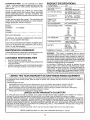
SPECIFICATIONS
HORSEPOWER:
15.5
GASOLINE CAPACITY
AND TYPE:
5 QUARTS
UNLEADED
OIL TYPE (APt-SF/SG):
SAE 10W30 (above 32°F)
SAE 5W-30 (below 32 F)
OIL CAPACITY:
W/FILTER:
W/O FILTER:
SPARK PLUG:
(GAP: .040")
CHAMPION
VALVE CLEARANCE:
NOT ADJUSTABLE
GROUND SPEED (MPH):
FORWARD:
1st
2nd
3rd
4th
5th
6th
REVERSE:
917.256600
SERIAL
NUMBER
DATEOFPURCHASE
THEMODELANDSERIALNUMBERSWILLBEFOUND
ON A PLATE UNDER THE SEAT.
YOU SHOULD RECORD BOTH SERIAL NUMBER AND
DATE OF PURCHASE AND KEEP IN A SAFE PLACE
FOB FUTURE REFERENCE.
MAINTENANCE
AGREEMENT
A Sears Maintenance
Agreement is available on this product. Contact your nearest Sears store for details.
CUSTOMER
•
•
-
4.0 PINTS
3.5 PINTS
RC12YC
1.1
1.4
2.3
3.5
4.5
5.7
1.8
TIRE PRESSURE:
FRONT:
REAR:
14 PSI
10 PSi
CHARGING SYSTEM:
3 AMPS BATTERY
5 AMPS HEADLIGHTS
?,ATTERY:
AMP/HR:
MIN. CCA:
CASESIZE:
BLADE BOLT TORQUE:
30-35 FT. LBS.
30
240
U1R
WARNING:
This tractor is equipped with an internal
combustion engine and should not be used on or near any
unimproved forest-covered, k3rush-covered or grass-covered land unless the engine's exhaust system is equipped
with a spark arrester meeting applicable local or state laws
(if any). If a spark arrester is used, it should be maintained
Lneffective working order by the operator.
In the state of California the above is required by law
oSection 4442 of the California Public Resources Code).
ther states may have similar laws. Federal laws apply on
federal lands. A spark arrester for the muffler is available
through your nearest Sears Authorized Service Center!
Department (See REPAIR PARTS section of this manual).
RESPONSIBILITIES
Read and observe the safety rules.
Follow a regular schedule in maintaining, caring for and
using your tractor.
Follow the instructions under "Customer Responsibilities" and "Storage" sections of this owner's manual.
LIMITED TWO YEAR WARRANTY
REGULAR
ON CRAFTSMAN
RIDING EQUIPMENT
For two (2) years from the date of purchase, if this Craftsman Riding Equipment is maintained, lubricated and tuned up according to
the instructions in the owner's manual, Sears will repair or replace, free of charge, any parts found to be detective in material or
workmanship.
This Warranty does net cover:
,,
Expendable items which become worn during normal use, such as blades, spark plugs, air cleaners, belts, etc.
=
Tire replacement or repair caused by punctures from outside objects, such as nails, thorns, stumps, or glass.
*
Repairs necessary because of operator abuse, negligence, improper storage or accident or the failure to maintain the
equipment according to the instructions contained in the owner's manual.
=
Riding equipment used for commercial or rental purposes.
LIMITED
90 DAY WARRANTY
ON BATTERY
For ninety (90) days from date of purchase, if any battery included with this tiding equipment proves defective in material or
workmanship and our testing determines the battery will not hold a charge, Sears will replace the battery at no charge.
IN-HOME WARRANTY SERVICE ON YOUR CRAFTSMAN RIDING EQUIPMENT IS AVAILABLE AT NO-CHARGE FOR 30 DAYS
FROM THE DATE OF PURCHASE. PLEASE CONTACT YOUR NEAREST SERVICE CENTER. AFTER 30 DAYS FROM THE
DATE OF PURCHASE, WARRANTY SERVICE IS AVAILABLE BY TAKING YOUR CRAFTSMAN RIDING EQUIPMENT TO YOUR
NEAREST SEARS-SERVICE CENTER.-(IN_HOMEWqARRANTY
SERVICE WtLL STILL BE AVAILABLE AFTER 30 DAYS FROM
THE DATE OF PURCHASE BUT A STANDARD TRIP CHARGE WILL APPLY.) THiS WARRANTY APPLIES ONLY WHILE THIS
PRODUCT IS IN THE UNITED STATES.
This Warranty gives you specific legal rights, and you may also have other rights which may vary from state to state.
SEARS, ROEBUCK AND CO., D/817 WA, HOFFMAN ESTATES, IL 60179
3
TABLE OF CONTENTS
OPERATION ..........................................................
11-15
MAINTENANCE SCHEDULE .....................................
16
SERVICE AND ADJUSTMENTS ........................... 20-25
STORAGE ...................................................................
26
TROUBLESHOOTING ...........................................
27-28
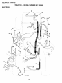
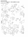
REPAIR PARTS - TRACTOR ................................
30-47
REPAIR PARTS- ENGINE ....................................
48-53
PARTS ORDERING/SERVICE .................. BACK PAGE
SAFETY RULES ............................................................
2
PRODUCT SPECIFICATIONS ...................................... 3
CUSTOMER RESPONSIBILITIES ..................... 3, 16-19
WARRANTY ..................................................................
3
TABLE OF CONTENTS ................................................. 4
INDEX ............................................................................
4
TRACTOR ACCESSORIES ..........................................
5
ASSEMBLY .............................................................
7-10
INDEX
A
Accessories ............................................ 5
Adjustments"
Brake ...........................................
22
Carburetor ................................... 25
Mower:
Front-To-Back ........................ 21
Side-To-Side .......................... 20
Throttle Control Cable ................. 25
Air Filter, Engine ................................. 18
Air Screen, Engine ............................. 18
Assembly .........................................
7-!0
B
Battery:
Charging .......................................
Cleaning ......................................
Starting with Weak Battery ..........
Storage .......................................
Terminals ....................................
Belts:
Motion Drive
Removal/Replacement ...........
Mower Blade Drive
Removal/Replacement ...........
Blade:
Sharpening ..................................
Replacement ...............................
Brake Adjustment ...............................
C
8
17
24
26
!7
23
22
17
17
22
Carburetor Adjustment ....................... 25
Controls, Tractor ................................
12
Customer Responsibilities ............. 16-19
Engine:
Air Filter ...................................
18
Air Screen, Engine .................. 18
Battery .....................................
17
Cooling Fins, Engine ............ _.. 19
Engine Oil ..............................
!7
Fuel Filter ................................
19
Spark Plugs ............................. 19
Tractor:
Blades .....................................
17
Lubdcation Chart ..................... 16
Maintenance Schedule ........... 16
Tire Care ......................... 8,17,24
Cutting Height, Mower ........................ 13
.........
_-"
.....
E
Engine:
Air Filter .......................................
18
Air Screen ................................... 18
Cooling Fins, Engine ................... 19
Oil Change .................................. 18
Oil Level ................................. 14,18
Oil Type .......................................
18
Preparation ................................. 14
Repair Parts ........................... 48-53
Starting ........................................
14
Storage .......................................
26
F
Filters:
Air ................................................
18
Fuel .............................................
19
Fuel:
Type ............................................
14
Storage ....................................... 26
Fuse ...................................................
24
G
Gauge Wheels ................................... 14
H
Hood Removal/Installation ................. 24
L
Leveling Mower Deck ......................... 20
Lubrication Chart ................................ 16
M
Maintenance Schedule ...................... 16
Mower:
Adjustment, Front-to-Back .......... 21
Adjustment, Side-to-Side ............ 20
Blade Sharpening ....................... 17
Blade Replacement ..................... 17
Cutting Height ............................. 13
Installation ................................... 20
Operation ................................... 1 4
Removal ...................................... 20
Mowing Tips .......................................
15
Muffler ................................................
19
Spark Arrester .......................... 3,40
Mulcher P]ate ..................................... 10
O
Oil:
Cold Weather Conditions ....... 14,18
Engine .........................................
18
Storage ............
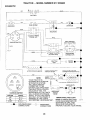
Electrical:
Inter!ocks and Relays ................. 24
Schematic ...................................
29
Wiring Diagram ........................... 30
4
"7-': ......................26 ....
Operation ......................................
11-15
Operating Mower ................................ 14
Options:
Accessories ...................................
5
Spark Arrester .......................... 3,40
P
Parking Brake ................................ 11-12
Parts Bag .............................................
6
Pads, Replacement/Repair
........... 30-47
Product Specifications ........................... 3
R
Repair Parts .................................. 30-47
S
Safety Rules .........................................
2
Seat ......................................................
8
Service and Adjustments .............. 20-25
Brake ...........................................
22
Carburetor ................................... 25
Fuse ............................................
24
Hood Removal/Installation .......... 24
Motion Drive Belt
Removal/Replacement ........... 23
Mower Blade Drive Belt
Removal/Replacement ........... 22
Mower Adjustment:
Front-to-Back ......................... 21
Side-to-Side ........................... 20
Mower Installation ....................... 20
Mower Removal .......................... 20
Tire Care ...... :..................... 8,1 7,24
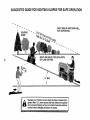
Slope Guide Sheet ............................. 55
Spark Plugs ........................................
19
Specifications .......................................
3
Starting the Engine ....................... 14-15
Steering Wheel ................................ 7,23
Stopping the Tractor ........................... 13
Storage ...............................................
26
T
Throttle Control Cable Adjustment ..... 24
Tires ...........................................
8,17,24
Trouble Shooting Chart .................. 27-28
Transaxle Repair Parts ................. 46-47
W
Warranty ...............................................
3
Wiring Diafl ram-=:=_-=:
:........ ;-;-=.:.. 30-Wiring Schematic ............................... 29
ACCESSO
ATTACHMENTS
These accessories and attachments were available through most Sears retail outlets and service centers when the tractor was purchased.
Most Sears stores can order these items for you when you provide the model number of your tractor.
ENGINE
SPARK PLUG
MAINTENANCE
GAS CAN
ENGINE OIL
FUEL STABILIZER
AIR FILTER
BLADES
BELTS
%
PERFORMANCE
Sears offers a wide variety of attachments that fit your tractor, Many of these are listed below with brief explanations of how they can help
you. This list was current at the time of publication; however, it may change in future years - more attachments may be added, changes
may be made in these attachments, or some may no longer be available or fit your model. Contact your nearest Sears store for the
accessories and attachments
that are available for your tractor.
Most of these attachments do not require additional hitches or conversion kits (those that do are indicated) and are designed for easy
attaching and detaching.
AERATOR promotes deep root growth for a healthy lawn. Tapered 2,5-inch steel spikes mounted on 10-inch diameter discs
puncture holes in soil at close intervals to let moisture soak in.
Steel weight tray for increased penetration.
BAGGER lets you collect
grass clippings and leaves for a
healthier, neater looking lawn. Two Permanex containers hold
30-gallon plastic bags.
BUMPER protects front end of tractor from damage.
CARTS make hauling easy. Variety of sizes available, plus
accessories such as side panel kits, tool caddy, cad cover,
protective mat and dolly.
CORING AERATOR takes small plugs out of soil to allow moisture and nutrients to reach grass roots. 36-inch swath. 24
hardened steel coring tips. 150 lb. capacity weight tray.
EASY OIL DRAIN VALVE makes oil changes easier, faster.
FRONT NOSE ROLLER canters in front of mower deck to reduce
chances of "scalping" on uneven terrain.
GANG HITCH lets you tow 2 or 3 pull-behind attachments at once,
such as sweepers, dethatchers, aerators (not for use with rollers,
carts or other heavy attachments).
GAUGE WHEELS on both sides of the mower deck reduce
chances of "scalping" on uneven terrain. For mowerdecks not so
equipped.
MULCH RAKE./DETHATCHER loosens soil and flips thatch and
matted leaves to lawn surface for easy pickup. Twenty spring tine
teeth. Useful to prepare bare areas for seeding. Available for front
or rear mounting.
HIGH PERFORMANCE
REEL-ACTION
SPRING TINE DETHATCHER covers 36-inch wide path and
tosses thatch into large hopper. Mounts behind tractor.
MULCHING CLOSE-OUT PLATE KIT, once installed, lets you
mulch, discharge or bag clippings (bagger optional) without
changing blades. For models not equipped as 3-in-1 Convertible
mowers.
See "MOWER" in the Repair Parts section of this
manual.
SNOWBLADEforsnowremovalonly.
14-inch high, 48-inchwide
bladeclea rs 42-inch path when angled left or right. Raises, lowers
with side lever. Adjustable skids; replaceable, reversible scraper
bar. (Use with tirechains and wheel weights and/or rear drawbar
weight.)
SNOWTHROWER has 40-inch swath. Drum-type auger handles
powdery and wet/hea W snow. Mounts easily with simple pin
arrangement. Discharge chute adjusts from tractor seat. 6-inch
diameter spout discharges snow 10 to 50 feet. Lift controlled at
tractor seat. (Use with chains and wheel weights and/or rear
drawbar weight.)
SPRAYERS use 12-volt DC electric motor that connects to the
tractor battery or other 12-volt source.
Includes booms for
automatic spraying and hand herd wand for spot spraying. Wand
has adjustable spray pattern. For applying herbicides, insecticides, fungicides and liquid fertilizers.
SPREADERfSEEDERS
make seeding, fertilizing, and weed killing easy. Broadcast spreaders are also useful for granular deicers and sand.
SWEEPERS let you collect grass clippings and leaves.
TILLER has 5 hp engine and 36-inch swath to prepare seed beds,
cultivate and compost garden residue. Tiller has its own built-in
lift and depth controt system and does NOT require a sleeve hitch.
Fits any lawn, yard or garden tractor. Simply hook up to the tractor
drawbar and got Optional accessories
convert unit for
dethatching, aerating, hilling...without tools.
TIRE CHAINS are heavy duty; closely spaced extra-large cross
links give smooth ride, outstanding traction.
TRACTOR CAB has heavy duty vinyl fabric over tubular steel
frame, ABS plastic top; clear plastic windshield offers 360 degree
visibility. Hinged metal doors with catch. Keeps operator warm
and dry. Remove vinyf sides and windshields for use as sun
protector in summer. Optional accessories include: tinted/
tempered solid safety glass windshield with hand operated wiper;
12-volt amber caution light for mounting on cab top.
RAMP TOPS AND FEET let you load and unload tractor from a
VACS for powerful collection ot heavy grass clippings and leaves.
pickup truck. Use with 2 x 8 or 2 x 10 lumber.
Optional wand attachment to pick up debris in hard-to-reach
places. VAC/CHIPPER includes a chipper*shredder.
ROLLER for smoother lawn surface.
36-inch wide, 18-inch
diameter water-tight drum holds up to 390 Ibs. of weight. Rounded
WEIGHT BRACKET for drawbar for snow removal applications.
edges prevent, harm _Q turf.i. Adjustable scraper automatically ....... Uses_(])551b_.weight ..................................................
cleans drum.
WHEEL WEIGHTS for rear wheels provide needed traction for
snow removal or dozing heavy materials.
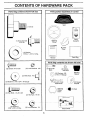
CONTENTS
Parts Bag contents
OF HARDWARE
shown full size
PACK
Parts packed separately
in carton
Seat
(1) Knob
Video
Cassette
Steering
Wheel
(1) Shoulder Bolt
5/16-18
Mulcher
Plate
(1) Was her
17/32 x 1-3/16 x 12 Ga.
i
Manual
Parts Bag
Parts bag contents
not shown
full size
©
(2) Lock Washers
(2) Screws #10 x 5/8
#10
(2) Shoulder
Bolts
(2) Center!ock Nuts
(2) Washers 3/8
x 7/8 x 14 Gauge
Steering
Sleeve
Latch Hook
Assemblies
12)Gauge
Wheels
(2) Weld Nuts #10 L_
(2) Washers
_==_)
3/16 x 3/4 x 16 Gauge
Steering
Wheel
Insert
i
(2) Hex Bolts 1/4-20 x 3/4
(2) Hex Nuts 1/4-20
(2) Washers
9/32 x 5/8 x 16 Ga.
(2) Lock Washers
1/4
Slope Sheet
(2) Keys
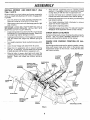
ASSEMBLY
i
Your new tractor has been assembled at the factory with exception of those parts left unassembled for shipping purposes.
To ensure safe and proper operation of your tractor all parts and hardware you assemble must be tightened securely. Use
the correct tools as necessary to insure proper tightness.
TOOLS REQUIRED
FOR ASSEMBLY
ii
A socket wrench set will make assembly easier. Standard
wrench sizes are listed.
(2) 7/16" wrenches
Utility knife
(1) 1/2" wrench
Phillips Screwdriver
(1) 9/16" wrench
Tire pressure gauge
_-
STEERING
'_,..-/
WHEEL
_
LOCKNUT
INSERT
- ARGE
FLAT
WASHER
(1) 3/4" Socket w/drive rachet
WHEEL
When right or left hand is mentioned in this manual, it
means when you are in the operating position (seated
behind the steering wheel).
TO REMOVE TRACTOR FROM CARTON
UNPACK
-
STEERING _
WHEEL
ADAPTER
CARTON
Remove all accessible loose parts and parts cartons
from carton (See page 6).
._
_)
/
%_-_-_-'J
._
• _ /
,.: p:"
Check for any additional loose parts or cartons and
remove.
BEFORE
SKID
ATTACH
-
ROLLING
TRACTOR
I
I
t
_
OFF
/STEERING
/
SLEEVE
,
_.-I
y"
"-It 1
/
t/I
iI
/
I
I
FIG. 1
STEERING
WHEEL
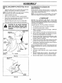
(See Fig. 1)
TO ROLL TRACTOR
Remove Iocknut and large flat washer from steering
shaft,
Raise attachment lift lever to its highest position,
Release parking brake by depressing clutch/brake
pedal.
Place gearshift lever in neutral (N) position.
Roll tractor backwards off skid.
Position front wheels of the tractor so they are pointing
straight forward,
-
Slide the steering sleeve over the steering shaft,
•
•
Position steering wheel so cross bars are horizontal
(left to right) and slide onto adapter.
Secure steering wheel to steering shaft with Iocknut
and large flat washer previously removed. Tighten
securely•
Snap steering wheel insert into center of steering
wheel.
•
Remove protective plastic from tractor hood and grill.
IMPORTANT: CHECK FOR AND REMOVE ANY STAPLES
IN SKID THAT MAY PUNCTURE TIRES WHERE TRACTOR
IS TO ROLL OFF SKID,
7
OFF SKID (See Fig. 6)
•
-
-
/.
t
•
-
SHAFT
Cut, from top to bottom, along lines on all four corners
of carton, and lay panels tlat.
Remove mower and packaging materials.
I
=
_,/
STEERING
ASSEMBLY
CONNECT
BATI'ERY
(See Fig. 2)
INSTALL
SEAT (See Fig. 3)
Adjust seat before tightening adjustment knob.
CAUTION: Do not short battery terminals. Before connecting battery, remove metal bracelets,
wristwatch
bands, rings, etc.
Remove cardboard packing on seat pan.
Positive terminal must be connected
first to prevent sparking from accidental grounding.
,,
Lift hood to raised position.
,,
Open terminal access doors, remove terminal protective caps and discard.
•
If this battery is put into service after month and year
indicated on label (label located between terminals)
charge battery for minimum of one hour at 6-10 amps.
•
First connect RED battery cable to positive (+) battery
terminal with hex bolt, flat washer, lock washer and hex
nut as shown. Tighten securely.
•
•
•
Place seat on seat pan and assemble shoulder bolt.
=
Assemble adjustment knob and fiat washer loosely.
Do not tighten.
=
Tighten shoulder bolt securely.
•
Lower seat into operating position and sit on seat.
•
Slide seat until a comfortable position is reached which
allows you to press clutch/brake pedal all the way
down.
•
Get off seat without moving its adjusted position.
•
Raise seat and tighten adjustment knob securely.
SEAT PAN
SEAT
SHOULDER
BOLT
Connect BLACK grounding cable to negative (-) battery
terminal with remaining hex bolt, flat washer, lock
washer and hex nut. Tighten securely.
Close terminal access doors.
Use terminal access doors for:
•
Inspection for secure connections
ware).
•
inspection for corrosion.
•
Testing battery.
•
Jumping (if required).
(to tighten hard-
FIG. 3
Periodic charging.
HEX NUT
FLAT WASHER
ADJUSTMENT
KNOB
CHECK TIRE PRESSURE
LOCK
WASHER
FLAT
WASHER
DISCARD TERMINAL
PROTECTIVE CAPS
The tires on your tractor were overinflated at the factory for
shipping purposes. Correct tire pressure is important for
best cutting performance.
HEX
BOLT
•
Reduce tire pressure to PSI shown in "PRODUCT
SPECIFICATIONS" on page 3 of this manual.
CHECK
BRAKE
SYSTEM
After you learn how to operate your tractor, check to see
that the brake is properly adjusted. See "TO ADJUST
BRAKE" in the Service and Adjustments section of this
manual.
POSITIVE
(RED)
CABLE
NEGATIVE
(BLACK)
CABLE
FIG. 2
8
BLY
INSTALL
MOWER
AND
DRIVE
BELT
(See
m
Place the R.H. suspension arm on outward pointing
deck pin. If necessary, rock and raise front of mower
to align deck pin with the hole in suspension arm.
-
Connect anti-sway bar to chassis bracket under left
footrest and retain with double loop retainer spring.
•
Retain both suspension arms to deck pins with double
loop retainer springs.
Turn height adjustment knob clockwise to remove
slack from mower suspension.
Figs. 4 and 6)
Be sure tractor is on Level surface and mower suspension
arms are raised with attachment lift control. Engage parking brake.
•
Cut and remove tie down securing anti-sway
Swing anti-sway bar to left side of mower deck.
bar.
°
Slide mower under tractor with discharge guard to right
side of tractor.
=
IMPORTANT: CHECK BELT FOR PROPER ROUTING IN
ALL MOWER PULLEY GROOVES. INSTALL BELT INTO
ELECTRIC CLUTCH PULLEY GROOVE.
•
Install one front link in top hole of the RH. front mower
bracket and R.H. front suspension bracket. Retain with
two single loop retainer springs as shown.
•
Install second front link in L.H. front suspension bracket
only and retain with single loop retainer spring as
shown.
•
Turn height adjustment knob counterclockwise
stops.
•
Lower mower linkage with attachment lift control.
-
Place the L.H. suspension arm on outward pointing
deck pin. If necessary, rock and raise front of mower
to align deck pin with the hole in suspension arm.
Slide left side of mower deck back and install the
unattached front link in top hole of the L.H. front mower
bracket. Retain with single loop retainer spring as
shown.
•
CHASSIS
BRACKET
Raise deck to highest position.
,,
Assemble gauge wheels (See "TO ADJUST GAUGE
WHEELS" in the Operation section of this manual).
CHECK
DECK LEVELNESS
For best cutting results, mower housing should be properly
leveled. See 'q-O LEVEL MOWER HOUSING" in the
Service and Adjustments section of this manual.
CHECK
BELTS
until it
DOUBLE LOOP
RETAINER SPRING
(outward pointing
deck pins)
•
FOR
PROPER
POSITION
See the figures that are shown for replacing motion, mower
drive, and mower blade drive belts in the Service and
Adjustments section of this manual. Verify that the belts
are routed correctly.
FRONT
SUSPENSION
BRACKETS
ELECTRIC
CLUTCH
PULLEY'
SUSPENSION
ARMS
FRONT
MOWER
BRACKET
r
SHOULDER
BOLT
GAUGE
WHEEL
OF ALL
FRONT
LINK
SINGLE
LOOP
RETAINER
SPRINGS
_8-16
CENTER
LOCKNUT
3/SWASHER
ANTI-SWAY
BAR
........
DOUBLE LOOP
RETAINER
SPRING
........
IDEER
PULLEY
DISCHARGEGUARD
FIG. 6
9
ASSEMBLY
m
INSTALL
MULCHER
PLATE (See Figs. 5A and
TO CONVERT TO BAGGING
DISCHARGING
5B)
-
Install two latch hooks to mulcher plate using screw,
washer, lock washer, and weld nut as shown.
Simply remove mulcher plate and store in a safe place.
Your mower is now ready for discharging or installation of
optional grass catcher accessory.
NOTE: Pre-assemble weld nut to latch hook by inserting
weld nut from the top with hook pointing down.
.
Tighten hardware securely.
-
Raise and hold deflector shield in upright position.
•
•
Place front of mulcher plate over front of mower deck
opening and slide into place, as shown.
Hook front latch into hole on front of mower deck.
•
Hook rear latch into hole on back of mower deck.
&
NOTE: It is not necessaryto change blades. The mulcher
blades are designed for discharging and bagging also.
v"CHECKLIST
BEFORE YOU OPERATE AND ENJOY YOUR NEW
TRACTOR, WE WISH TO ASSURE THAT YOU RECEIVE
THE BEST PERFORMANCE A ND SA TISFA CTION FROM
THIS QUALITY PRODUCT.
CAUTION: Do not remove discharge
guard from mower. Raise and hold
guard when attaching mulcher plate
and allow it to rest on plate while in
operation.
PLEASE REVIEW THE FOLLOWING CHECKLIST:
HOOK POINTS
DOWN
WELD NUT
FROM THE TOP
LOCK
WASHER
WELD.
NUT
,/
Al! assembly instructions have been completed.
,/
No remaining loose parts in carton.
•/
Batteryis properly prepared and charged.
1 hour at 6 amps).
,/
Seat is adjusted comfortably and tightened securely.
,/
All tires are properly inflated. (For shipping purposes,
the tires were overinflated at the factory).
#"
Be sure mower deck is properly leveled side-to-side/
front-to-rear for best cutting results. (Tires must be
properly inflated for leveling).
,/
Check mower and drive belts. Be sure they are routed
properly around pulleys and inside all belt keepers.
,/
Checkwiring. See that atl connections are still secure
and wires are properly clamped.
SCREW
"_
LATCH
HOOK
LOCK
WASHER
WELD
NUT
,/
Engine oil is at proper level.
,/
Fuel tank is filled with fresh, clean, regular unleaded
gasoline.
Become familiar with all controls - their location and
function. Operate them before you start the engine.
WASHER
\__.._
,/
SCREW
,/
FiG. 5A
DEFLECTOR
SHIELD
it\"
JJk' l\
_"
(Minimum
WHILE LEARNING HOWTO USE YOUR TRACTOR, PAY
EXTRA A TTENTION TO THE FOLL OWING IMPORTANT
ITEMS:
WASHER
MULCHER
PLATE
OR
LATCH
HOOKS
FIG. !iB
10
Be sure brake system is in safe operating condition.
OPERATION
These symbols may appear on your tractor or in literature supplied with the product. Learn and understand their meaning.
BATTERY
CAUTION OR
WARNING
ENG INE ON
ENGINE OFF
FUEL
CHOKE
REVERSE
OILPRESSURE
MOWER HEIGHT
FORWARD
FAST
SLOW
CLUTCH
LIGHTS ON
LIGHTS OFF
DIFFERENTIAL
LOCK
PARKING BRAKE
LOCKED
UNLOCKED
R N H
REVERSE
MOWER LIFT
NEUTRAL
ATTAC H MENT
CLUTCH ENGAGED
HIGH
LOW
ATTACHMENT
CLUTCH DISENGAGED
PARKING BRAKE
IGNITION
HYDROSTATIC FREE WHEEL
(Hydro Models only)
DANGER, KEEP HANDS AND FEET AWAY
11
OPERATION
w
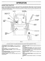
KNOW YOUR TRACTOR
READ THIS OWNER'S
MANUAL
AND SAFETY
RULES
BEFORE
OPERATING
YOUR
TRACTOR
Compare the illustrations with your tractor to familiarize yourself with the locations of various controls and adj ustments. Save
this manual for future reference.
AMMETER
ATTACHMENT
CLUTCH SWITCH
THROTTLE/CHOKE
CONTROL
- - - - - ~
_ _ ..
LIFT LEVER
PLUNGER
LIGHT
SWITCH
ATTACHMENT
LIFT LEVER
CLUTCH/
BRAKE
PEDAL
IGNITION
SWITCH
PARKING
BRAKE
HEIGHT
ADJUSTMENT
KNOB
GEARSHIFT
LEVER
FIG. 6
Our tractors conform to the safety standards of the American National Standards Institute,
ATTACHMENT CLUTCH SWITCH: Used to engage the
mower blades, or other attachments mounted to your
tractor.
GEAR SHIFT LEVER - Selects the speed and direction of
the tractor.
ATTACHMENT LIFT LEVER: Used to raise and lower the
mower deck or other attachments mounted to your tractor.
LIFT LEVER PLUNGER: Used to release attachment lift
lever when changing its position.
LIGHT SWITCH: Turns the headlights on and off.
THROTTLE/CHOKE
speed.
CONTROL:
Used to control engine
CLUTCH/BRAKE PEDAL: Used for declutching and braking the tractor and staAing the engine_
...............
IGNITION SWITCH: Used for starting and stopping the
engine__ .....................
PARKING BRAKE:
brake position,
HEIGHTADJUSTMENTKNOB:
cutting height.
Locks clutch/brake
pedal into the
AMMETER:
(-).
12
Used toadjustthe mower
Indicates battery charging (+) or discharging
OPERATION
The operation of any tractor can result in foreign objects thrown into the eyes, which can
result in severe eye damage. Always wear safety glasses or eye shields while operating your
tractor or performing any adjustments or repairs. We recommend a wide vision safety mask
over the spectacles or standard safety glasses.
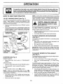
HOW TO USE YOUR TRACTOR
TO SET PARKING
BRAKE
NOTE: Under certain conditions when tractor is standing
idle with the engine running, hot engine exhaust gases may
cause "browning" of grass. To eliminate this possibility,
always stop engine when stopping tractor on grass areas.
(See Fig. 7)
Your tractor is equipped with an operator presence sensing
switch. When engine is running, any attempt by the
operator to leave the seat without first setting the parking
brake will shut off the engine.
o
Depress clutch/brake pedal into full "BRAKE" position
and hold.
•
Place parking brake !ever in"ENGAGED" position and
release pressure from clutch/brake pedal. Pedal should
remain in "BRAKE" position. Make sure parking brake
wi!l hold tractor secure.
PARKING BRAKE
"ENGAGED"
POSITION
ATTACHMENT CLUTCH
SWITCH PULL OUT TO
"ENGAGE"
&
CAUTION: Always stop tractor completely, as described above, before leaving the operator's position; to empty
grass catcher, etc.
TO USE THROTTLE
CONTROL
*
Operating engine at less than full throttle reduces the
battery charging rate.
,
Full throttle offers the best mower performance.
I
I
TO MOVE FORWARD
'HROTTLF_/CHOKEI
CONTROL
AND BACKWARD
(See Fig. 7)
The direction and speed of movement
gearshift lever.
"BRAKE"
POSITION
-_"DIS
CLUTCH/BRAKE
PEDAL "DRIVE"
POSITION
ENGAGED"
POSITION
E
LEVER
HEIGHT
ADJUSTMENT
KNOB
clutch switch to "DISENGAGED"
GROUND DRIVE •
o
•
Move gearshift lever to desired
•
CUTTING
•
Turn knob clockwise (fN)
o
Turn knob counterclockwise
height.
lever to neutral (N) position.
Move throttle control to slow (,,gb) position.
-
NOTE:
Failure to move throttle control to slow (,_!,)
position and allowing engine to idle before stopping may
cause engine t0 "bac_ire".
........
,
position.
HEIGHT
to raise cutting height.
(_-_)
to lower cutting
The cutting height range is approximately 1-1/2" to 4% The
heights are measured from the ground to the blade tip with
the engine not running. These heights are approximate
and may vary depending upon soil conditions, height of
grass and types of grass being mowed.
Depress clutch!brake pedal into full "BRAKE" position.
Move gearshift
ENGINE -
Start tractor with clutch/brake pedal depressed and
gearshift lever in neutral (N) position.
The cutting height is controlled byturning the height adjustment knob in desired direction.
(See Fig. 7)
Move attachment
position.
o
TO ADJUST MOWER
(See Fig. 7)
MOWER BLADES •
is controlled by the
Slowly release clutch/brake pedal to start movement.
IMPORTANT: BRINGTRACTORTOA
COMPLETE STOP
BEFORE SHIFTING OR CHANGING GEARS. FAILURE
TO DO SO WILL SHORTEN THE USEFUL LIFE OF YOUR
TRANSAXLE.
FIG. 7
STOPPING
(See Fig. 7)
Always operate engine at full throttle.
•
Turn ignition key to "OFF" position and remove key.
Always remove key when leaving tractor to prevent
unauthorized use.
The average lawn should be cut to approximately 2-1/2
inches during the cool season and to over 3 inches
during hot months.
For healthier and better looking
....
lawns, mow or[en-ana ar_er moa_ral:_rgro_n.-..........
For best cutting performance, grass over 6 inches in
height should be mowed twice. Make the first cut
relatively high; the second to desired height.
Never use choke to stop engine.
13
m
OPERATION
TO ADJUST
GAUGE
WHEELS
(See Fig. 8)
Adjust gauge wheels with tractor on a flat level surface.
Adjust mower to desired cutting height (See "TO ADJUST MOWER CUTTING HEIGHT" in the Operation
section of this manual).
With mower in desired height of cut position, gauge
wheels should be assembled so they are slightly off the
ground. Install gauge wheel in appropriate hole with
shoulder bolt, 3/8 washer, and 3/8-18 Iocknut and
tighten securely.
Repeat for opposite side installing gauge wheel in
same adjustment hole.
TO OPERATE
hills
with slopes
greater
15 °down
and
CAUTION:
Do not
drive than
up or
do not drive across any slope.
_'_\
_-_._
"\_ _
_ _
MOUNTING
_..
_
•
•
_
•
LOCKNUT
_
3J8
_._..
•
SHOULDER
BOLT
GAUGE WHEEL_
MOWER
(See Fig. 9)
Your tractor isequipped with an operator presence sensing
switch. Any attempt by the operator to leave the seat with
the engine runningand the attachment clutch engaged will
shut off the engine.
Select desired height of cut.
Lower mower with attachment lift control.
°
Start mower blades by engaging attachment clutch
control.
=
TO STOP MOWER BLADES - disengage attachment
clutch control.
I&
without either the entire grass catcher,
on mowers so equipped, or the disCAUTION:
Doinnot
operate the mower
charge
guard
place.
ATTACHMENT CLUTCH
SWITCH PULL OUT TO
'=ENGAGE"
Avoid stopping or changing speed on hills.
if slowing is necessary, move throttle control lever to
slower position.
If stopping is absolutely necessary, push clutch/brake
pedal quickly to brake position and engage parking
brake.
Move gearshift lever to 1st gear. Be sure you have
allowed room for tractor to roll slightly as you restart
movement.
To restart movement, slowly release parking brake and
clutch/brake pedal.
Make all turns slowly.
TO TRANSPORT
,
FIG. 8
TO OPERATE
I
I
Choose the slowest speed before starting up or down
hills.
•
GUAGE
WHEEL
ON HILLS
Raise attachment lift to highest position with attachment lift control.
•
When pushing ortowing your tractor, be sure gearshift
lever is in neutral (N) position.
•
Do not push or tow tractor at more than five (5) MPH.
NOTE: To protect hood from damage when transporting
your tractor on a truck or a trailer, be sure hood is closed and
secured totractor. Use an appropriate means of tying hood
to tractor (rope, cord, etc.).
BEFORE
CHECK
HIGH POSITION
THE
ENGINE
ENGINE OIL LEVEL (See Fig. 15)
•
The engine in your tractor has been shipped, from the
factory, already filled with summer weight oil.
•
Check engine oil with tractor on level ground.
•
Unthread and remove oil fill cap/dipstick; wipe oil off.
Reinsert the dipstick into the tube and rest oil fill cap on
the tube. Do not thread the cap onto the tube. Remove
and read oil level. If necessary, add oil until "FULL"
mark on dipstick is reached. Do not overfill.
o
For cold weather operation you should change oil for
easier starting (See "OIL VISCOSITY CHART" in the
Customer Responsibilities section of this manual).
°
To change engine oil, see the Customer Responsibilities section in this manual.
ATTACHMENT
LIFT LEVER
_ _
STARTING
ADD GASOLINE
•
DISCHARGE
GUARD
FIG, 9
Fill fuel tank. Use fresh, clean, regular unleaded
gasolinewith a minimum of 87 octane. (Use of leaded
gasoline wil! increase carbon and lead oxide deposits
and reduce valve life). Do not mix oil with gasoline.
Purchase fuel in quantities that can be used within 30
IMPORTANT= WHEN OPERATING 1N TEMPERATURES
BELOW 32°F(0°C),
USE FRESH,
CLEANWINTER GRADE
GASOLINE TO HELP INSURE GOOD COLD WEATHER
STARTING.
WARNING:
Experience indicates that alcohol blended
fuels (called gasohol or using ethanol or methanol) can
attract moisture which leads to separation and formation of
14 acids during storage. Acidic gas can damage the fuel
OPERATION
system of an engine while in storage. To avoid engine
problems, the fuel system should be emptied before storage of 30 days or longer. Drain the gas tank, start the
engine and let it run until the fuel lines and carburetor are
empty. Use fresh fuel next season. See Storage Instructions for additional information.
Never use engine or
carburetor cleaner products in the fuel tank or permanent
damage may occur.
CAUTION: Fill to bottom of gas tank
filler neck. Do not overfill. Wipe off any
spilled oil or fuel. Do not store, spill or
use gasoline near an open flame.
TO START ENGINE
During engine warm-up, the equipment can be operated.
When starting engine for the first time or if engine has run
out of fuel, it will take extra cranking time to move fuel from
the tank to the engine.
•
•
•
Depress clutch!brake pedal and set parking brake.
Place gearshift lever in neutral (N) position.
Move attachment clutch to "DISENGAGED" position.
Move throttle control lever to choke (l\l) position for
cold engine start. For warm engine start, move throttle
control to fast (,_) position.
• Insert key into ignition and turn key clockwise to"START"
position and release key as soon as engine starts. Do
not run starter continuously for more than fifteen
seconds per minute. If engine does not start after
several attempts, move throttle control to fast (,_)
position, wait a few minutes and try again.
•
When engine starts, move throttle control to desired
position.
•
Allow engine to warm up for a few minutes before
engaging drive or attachments.
NOTE: If at a high altitude (above 3000 feet) or in cold
temperatures (below 32°F), the carburetor fuel mixture
may need to be adjusted for best engine performance. See
"TO ADJUST CARBURETOR" in the Service and Adjustments section of this manual.
=
•
•
(See Fig. 7)
This engine on this product is designed for maximum
perfomance and life if operated with the choke (N) fully
open and the throttle control in the fast (,_) position. To
open the choke fully requires an engine warm-up period of
several seconds to several minutes, depending on the
temperature.
After starting the engine, first open the choke slowly until
the engine just begins to run smoothly. Then open the
choke in small steps, allowing the engine to accept small
changes in speed and load, until the choke is fully open.
MOWING
-
TIPS
Tire chains cannot be used when the mower housing
is attached to tractor.
Mower should be properly leveled for best mowing
performance. See'q'O LEVEL MOWER HOUSING" in
the Service and Adjustments sectiofi0f thi_ma.-n-u_L....
= The left hand side of mower should be used for trimming.
•
Drive so that clippings are discharged onto the area
that has been cut. Have the cut area to the right of the
machine. This will result in a more even distribution of
clippings and more uniform cutting.
•
When mowing large areas, start by turning to the right 15
•
so that clippings will discharge away from shrubs,
fences, driveways, etc. After one or two rounds, mow
in the opposite direction making left hand turns until
finished (See Fig. 10 ).
If grass is extremely tall, it should be mowed twice to
reduce load and possible fire hazard from dried clippings. Make first cut relatively high; the second to the
desired height.
Do not mow grass when it is wet. Wet grass will plug
mower and leave undesirable clumps. Allow grass to
dry before mowing.
Always operate engine at full throttle when mowing to
assure better mowing performance and proper discharge of material. Regulate ground speed by selecting a low enough gear to give the mower cutting
performance as well as the quality of cut desired.
When operating attachments, select a ground speed
that will suit the terrain and give best performance of
the attachment being used.
FIG. 10
MULCHING
MOWING
TIPS
IMPORTANT:
FOR BEST PERFORMANCE,
KEEP
MOWER HOUSING FREE OF BUILT-UP GRASS AND
TRASH. CLEAN AFTER EACH USE.
•
The special mulching blade will recut the grass clippings many times and reduce them in size so that as
they fall onto the lawn they will disperse into the grass
and not be noticed. Also, the mulched grass will
biodegrade quickly to provide nutrients for the lawn.
Always mulch with your highest engine (blade) speed
as this will provide the best recutting action of the
blades.
•
Avoid cutting your lawn when it is wet. Wet grass tends
to form clumps and interferes with the mulching action.
The best time to mow your lawn is the early afternoon.
At this time the grass has dried and the newly cut area
will not be exposed to the direct sun.
•
For best results, adjust the mower cutting height so that
the mower cuts off only the top one-third of the grass
blades (See Fig. 11). For extremely heavy mulching,
reduce your width of cut and mow slowly.
•
Certain types of grass and grass conditions may require that an area be mulched a second time to completely hide the clippings. When doing a second cut,
mow across or perpendicular to the first cut path.
Change your cutting pattern from week to week. Mow
north to south one week then change to east to west the
next week. This will help prevent matting and graining
of the lawn.
MAX 1/3
FIG. 11
CUSTOMER
MAINTENANCE
RESPONSIBILITIES
SCHEDULE
FILL IN DATES
AS YOU COMPLETE
REGULAR SERVICE
3ERViCE DATES
Check Tire Pressure
v'_
V"
Check for Loose Fasteners
V"
Check
Brake Operation
r
I
iv'r
v"
i!
V'.
V"
a
Sharpen/Replace
Lubrication Chart
C
Check Battery Level/Recharge
v',
0
Clean Battery and Terminals
V"
a
Check Transa×le
v"
Adjust
L
Iv',
Mower Blades
Cooling
V"
v"
Blade Belt(s) Tension
V'5
r
Adjust Motion Drive Belt(s) Tension
Check
Change
v"
Engine Oil Level
v"
I
I
v'2
v'_
Clean Air Filter
E
Clean Air Screen
G
Inspect Muffler/Spark
J
E_
1234 -
V"
Engine Oil
i!
Arrester
Replace Oil Filter (If equipped)
_,2
Clean Engine Cooling
Replace Spark Plug
V'2
V'V'_
Fins
Replace
Air Filter Paper Cartridge
Replace
Fuel Filter
T
I
I J
V"
5 - If equippedwith adjustable system.
6 - Not required if equipped withmaintenance4ree battery.
7 - Tightenfront axle pivot bo_tto 35 ft.-1bs,maximum.
Do notovertighten.
Change more often when operating under a heavy ]earl or in high ambient temperatures.
Service more often when operating in dirty or dusty conditions.
If equipped wilh oil filter, change oil even/50 hours.
Replace blades more often when mowing in sandy soil.
GENERAL
i
LUBRICATION
RECOMMENDATIONS
CHART
®SPINDLE:
The warranty on this tractor does not cover items that have
been subjected to operator abuse or negligence.
To
receive full value from the warranty, operate r must maintain
tractor as instructed in this manual.
(_) FRONT
BEARING
Some adjustments will need to be made periodically to
properly maintain your tractor.
_BLE
ZERK®
"FRONT WHEEL(_)
BEARING ZERK
ZERK
All adjustments in the Service and Adjustments section of
this manual should be checked at least once each season,
•
Once a year you should replace the spark plug, clean
or replace air filter, and check blades and belts for
wear. A new spark plug and clean air filter assure
proper air-fuel mixture and help your engine run better
and last longer.
BEFORE
®
CLUTCH
PIVOT(S)
EACH USE
*
Check engine oil level.
.
Check brake operation.
fir_ nr,-,,=_, ,r,*,
•
®
O
PIVOTS
...........
O
Check for loose fasteners.
SAE30 OR 10W30 MOTOR OIL
GENERAL PURPOSE GREASE
.......................
L'z._
(_ REFER TO CUSTOMER RESPONSIBILITIES
"ENGINE" SECTION
IMPORTANT:
DO NOT OIL OR GREASE THE PIVOT POINTS
WHICH HAVE SPECIAL NYLON BEARINGS.
VISCOUS LUBRICANTS WILL ATTRACT
DUST AND DIRT THAT WILL SHORTEN
THE LIFE OF THE SELF-LUBRICATING
BEARINGS.
IF YOU
FEEL THEY MUST BE LUBRICATED,
USE ONLY A DRY, Pew16
DERED
GRAPHITE
TYPE
LUBRICANT
SPARINGLY.
CUSTOMER
RESPONSIBILITIES
TRACTOR
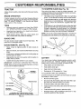
TO SHARPEN
Always observe safety rules when performing any maintenance.
Care should be taken to keep the blade balanced.
An
unbalanced blade wil! cause excessive vibration and eventual damage to mower and engine.
BRAKE
•
The blade can be sharpened with a file or on a grinding
wheel. Do not attempt to sharpen while on the mower.
•
To check blade balance, you will need a 5/8" diameter
steel bolt, pin, or a cone balancer. (When using a cone
balancer, follow the instructions supplied with balancer).
•
Slide blade on to an unthreaded portion of the steel bolt
or pin and hold the bolt or pin parallel with the ground.
If blade is balanced, it should remain in a horizontal
position. If either end of the blade moves downward,
sharpen the heavy end until the blade is balanced.
OPERATION
If tractor requires more than six (6) feet stopping distance
at high speed in highest gear, then brake must be adjusted.
(See '30 ADJUST BRAKE" in the Service and Adjustments section of this manual).
TIRES
•
Maintain proper air pressure in all tires (See "PRODUCT SPECIFICATIONS" on page 3 of this manual).
•
Keep tires free of gasoline, oil, or insect control chemicals which can harm rubber.
•
Avoid stumps, stones, deep ruts, sharp objects and
other hazards that may cause tire damage.
BLADE
(See Fig. 13)
NOTE: Do not use a nail for balancing blade. The lobes of
the center hole may appear to be centered, but are not.
CENTER HOLE
CARE
For best results mower blades must be kept sharp,
place bent or damaged blades.
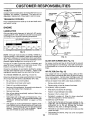
BLADE
BLADE
REMOVAL
Re-
(See Fig. 12)
=
Raise mower to highest position to allow access to
blades.
•
Remove hex bolt, lockwasher and flat washer secu ring
blade.
•
Install new or resharpened blade with trailing edge up
towards deck as shown.
.
Reassemble hex bolt, lock washer and flat washer in
exact order as shown.
BLADE
5/8" BOLT
OR PIN
FIG, 13
BATTERY
•
Tighten bolt securely (30-35 Ft. Lbs. torque).
IMPORTANT: BLADE BOLT IS GRADE 8 HEATTREATED.
Your tractor has a battery charging system which is sufficient for normal use. However, periodic charging of the
battery with an automotive charger will extend its life.
NOTE: We do not recommend sharpening blade - but if you
do, be sure the blade is balanced.
•
Keep battery and terminals clean.
•
Keep battery bolts tight.
=
Keep small vent holes open.
•
Recharge at 6-10 amperes for 1 hour.
BLADE
_
MANDREL
TO CLEAN BA-FFERY AND TERMINALS
Corrosion and dirt on the battery and terminals can cause
the battery to "leak" power.
_
ASSEMBLY
LOCK WASHER __--_---_
•
Remove terminal guard.
•
Disconnect BLACK battery cable first then RED battery cable and remove battery from tractor.
•
Rinse the battery with plain water and dry.
•
Clean terminals and battery cable ends with wire brush
until bright.
•
Coat terminals with grease or petroleum jelly.
•
Reinstall battery (See "CONNECT BATTERY" in the
Assembly sectionof this manua!)...
/
............... _-_*AGRADE8
HEAT TREATED BOLT CAN BE ....................
IDENTIFIED BY SIX LINES ON THE BOLT HEAD.
FIG. 12
17
CUSTOMER
RESPONSIBILITIES
V-BELTS
Check V-belts for deterioratio n and wear after 100 hours of
operation and replace if necessary. The belts are not
adjustable. Replace belts if they begin to slip from wear.
AIR CLEANER
COVER
TRANSAXLE COOLING
NUT
FOAM
PRE-CLEANER
Keep transaxle free from build-up of dirt and chaff which
can restrict cooling,
RUBBER
GROMMET
ENGINE
LUBRICATION
AIR CLEANER
_APER CARTRIDGE
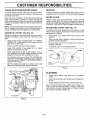
Only use high quality detergent oil rated with API service
classification SF or SG. Select the oil's SAE viscosity grade
according to your expected operating temperature.
AIR CLEANER
BASE
OIL FILL
CAP/DIPSTICK
SAE VISCOSITY GRADES
AIR
SCREEN
oF
.20 _
.3oo
0o
30 =
._o° -,o°
TEMPERATURE
RANGE
32 °
40 °
o°
ANTICIPATED
60 °
800
,o°
BEFORE
20°
NEXT
100 °
;o° _°
OIL CHANGE
FIG. 14
PLUG
NOTE: Although multi-viscosity oils (5W30, 10W30 etc.)
improve starting in cold weather, these multi-viscosity oils
will result in increased oil consumption when used above
32°F. Check your engine oil level more frequently to avoid
possible engine damage from running low on oil.
FIG. 15
CLEAN
Change the oil after the first two hours of operation and
ever), 50 hours thereafter or at least once a year if the
tractor is not used for 50 hours in one year.
Check the crankcase oil level before starting the engine
and after each eight (8) hours of operation. Tighten oil fill
cap/dipstick securely each time you check the oil level.
Your engine will not run properly using a dirty air filter,
Clean the foam pre-cleaner after every 25 hours of operation or every season. Service paper cartridge every 100
hours of operation or every season, whichever occurs first.
Determine temperature range expected before oil change.
All oil must meet API service classification SF or SG.
Be sure tractor is on level surface.
=
=
Oil will drain more freely when warm.
Catch oil in a suitable container.
•
Remove oil fill cap/dipstick. Be careful not to allow dirt
to enter the engine when changing oil.
-
Remove drain plug.
•
After oil has drained completely, replace oil drain plug
and tighten securely.
=
Refill engine with oil through oil fill dipstick tube. Pour
slowly. Do not overfill. For approximate capacity see
"PRODUCT SPECIFICATIONS"
on page 3 of this
manual
(See Fig. 15)
AIR FILTER (See Fig. 15)
TO CHANGE ENGINE OIL (See Figs. 14 and 15)
o
AIR SCREEN
Air screen must be kept free of dirt and chaff to prevent
engine damage from overheating, Clean with a wire brush
or compressed air to remove dirt and stubborn dried gum
fibers;
Service air cleaner more often under dusty conditions.
•
Remove knob and cover.
•
Remove wing nut and air cleaner from base.
TO SERVICE PRE-CLEANER
•
Slide foam pre-cleaner off cartridge.
•
Wash it in liquid detergent and water.
Squeeze it dry in a clean cloth.
•
Saturate it in engine oil, Wrap it in clean, absorbent
cloth and squeeze to remove excess oil.
TO SERVICE CARTRIDGE
=
.... _U_g-a:_--0n-_il
fill ca#/d0stick for _hecking level. .......
Insert dipstick into the tube and rest the oil fill cap on the
tube. Do not thread the cap onto the tube when taking
reading. Keep oil at "FULL" line on dipstick. Tighten
cap onto the tube securely when finished.
18
Gently tap the flat side of the paper cartridge to dislodg-e-_-rt7-, D_nSt_Wast_ th-e paper c&_i_lge or use
pressurized air, as this will damage the cartridge.
Replace a dirty, bent, or damaged cartridge.
Reinstall the pre-cleaner (cleaned and oiled) over the
paper cartridge.
Reassemble air cleaner, wing nut, cover and tighten
knob securely.
J
CUSTOMER
CLEAN
AIR INTAKE/COOLING
RESPONSIBILITIES
AREAS
MUFFLER
To insure proper cooling, make sure the grass screen,
cooling fins, and other external surfaces of the engine are
kept clean at all times.
Inspect and replace corroded muffler and spark arrester (if
equipped) as it could create a fire hazard and/or damage.
SPARK PLUGS
Every 100 hours of operation (more often under extremely
dusty, dirty conditions), remove the blower housing and
other cooling shrouds. Clean the cooling fins and extemal
surfaces as necessary. Make sure the cooNng shrouds are
reinstalled.
Replace spark plugs at the beginning of each mowing
season or after every 100 hours of operation, whichever
occurs first. Spark plug type and gap setting are shown in
"PRODUCT SPECIFICATIONS" on page 3 of this manual.
NOTE: Operating the engine with a blocked grass screen,
dirty or plugged cooling fins, and/or cooling shrouds removed will cause engine damage due to overheating.
ENGINE
OIL FILTER
IN-LINE FUEL FILTER
The fuel filter should be replaced once each season. If fuel
filter becomes clogged, obstructing fuel flow to carburetor,
replacement is required.
(See Fig. 16)
Replace the engine oil filter every season or every other oil
change if the tractor is used more than 100 hours in one
year.
,,
Drain oil from engine crankcase (See 'q-O CHANGE
ENGINE OIL" in this section of this manual, through
step remove drain plug).
,,
Remove oil filter and wipe off filter adapter.
•
Apply a thin coating of new engine oil to the rubber
gasket on replacement oil filter.
°
Install replacement oil filter on filter adapter. Turn oil
filter clockwise until rubber gasket contacts the filter
adapter, then tighten filter an additional 1/2 turn.
°
Fill crankcase with new oil (See "TO CHANGE ENGINE OIL" in this section of this manual). For approximate capacity see"PRODUCT SPECI FICATIONS" on
page 3 of this manual.
•
Start the engine and check for oil leaks. Correct any
leaks before placing engine into full operation.
(See Fig. 17)
=
With engine cool, remove filter and plug fuel line
sections.
=
Place new fuel filter in position in fuel line with arrow
pointing towards carburetor.
•
Be sure there are no fuel line leaks and clamps are
properly positioned.
•
Immediately wipe up any spilled gasoline.
CLAMP.
CLAMP
FUEL
FILTER
FIG. 17
CLEANING
•
Clean engine, battery, seat, finish, etc. of all foreign
matter.
•
Keep finished surfaces and wheels free of all gasoline,
oil, etc.
=
Protect painted surfaces with automotive type wax.
We do not recommend using a garden hose to clean your
tractor unless the electrical system, muffler, air filter and
carburetor are covered to keep water out. Water in engine
can result in a shortened engine life.
OIL FILTER
FIG. 16
19
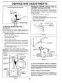
SERVICE AND ADJUSTMENTS
TO REMOVE
MOWER
TO LEVEL MOWER
(See Fig. 18)
=
Place attachment clutch in "DISENGAGED"
-
Turn height adjustment knob to lowest setting.
=
Lower mower to its lowest position.
Adjust the mower while tractor is parked on level ground or
driveway.
Make sure tires are properly inflated (See
"PRODUCT SPECIFICATIONS" on page 3 of this manual).
If tires are over or underinflated, you will not properly adjust
your mower.
position.
Remove retainer spring holding anti-swaybar to chassis bracket and disengage anti-swaybar from bracket.
Remove retainer springs from suspension
deck and disengage arms from deck.
HOUSING
SIDE-TO-SIDE ADJUSTMENT (See Figs. 19 and 20)
•
Raise mower to its highest position.
arms at
•
Raise attachment lift to its highest position.
o
•
Remove two retainer springs from each front link and
remove links.
Atthe midpoint of both sidesof mower, measure height
from bottom edge of mower to g round. Distance "A" on
both sides of mower should be the same or within 1/4"
of each other.
°
Slide mower forward and remove belt from electric
clutch pulley.
If adjustment is necessary, make adjustment on one
side of mower only.
°
Slide mower out from under right side of tractor.
IMPORTANT: IFAN ATTACHMENT OTHER THAN THE
MOWER DECK ISTO BE MOUNTED ON THE TRACTOR,
REMOVE THE FRONT LINKS.
=
To raise one side of mower, tighten lift link adjustment
nut on that side.
-
To lower one side of mower, loosen lift link adjustment
nut on that side.
TO INSTALL
NOTE: Each full turn of adjustment nut will change mower
height about 1/8".
MOWER
Follow procedure described in "INSTALL MOWER AND
DRIVE BELT" in the Assembly section of this manual.
Recheck measurements after adjusting.
BOTTOM EDGE
OF MOWER TO
GROUND
BOTTOM EDGE
OF MOWER TO
GROUND
GROUND LINE
ADJUSTMENT
NUTS
FIG. 19
LIFT
LINKS
FRONT
SUSPENSION
SUSPENSION
ARMS
BRACKET
CHASSIS
FRONT
SUSPENSION
BRACKET
//
RETAINER
SPRINGS
RETAINER
SPRING
ANTI-SWAY
BAR
FRONT MOWER
BRACKET
RETAINER
FIG. 18
2O
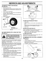
SERVICE AND ADJUSTMENTS
TO REPLACE
SUSPENSION
ARM
NUT
FIG. 20
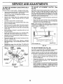
FRONT-TO-BACK ADJUSTMENT (See Figs. 21 and 22)
iMPORTANT: DECK MUST BE LEVEL SIDE-TO-SIDE. IF
THE FOLLOWING FRONT-TO-BACK ADJUSTMENT IS
NECESSARY, BE SURE TO ADJUST BOTH FRONT LINKS
EQUALLY SO MOWER WILL STAY LEVEL SIDE-TOSIDE.
To obtain the best cutting results, the mower housing
should be adjusted so that the front is approximately 1/4" to
3/4" lower than the rear when the mower is in its highest
position.
Check adjustment on right side of tractor. Measure distance "D" directly in front and behind the mandrel at bottom
edge of mower housing as shown.
•
Before making any necessary adjustments, check that
both front links are equal in length. Both links should be
approximately 10-3/8".
,,
If links are not equal in length, adjust one link to same
length as other link.
,,
To lower front of mower loosen nut "E" on both front
links an equal number of turns.
_, When distance "D" is 1/4" to 3/4" lower at front than
rear, tighten nuts "F" against trunnion on both front
links.
•
To raise front of mower, loosen nut"F" from trunnion on
both front links. Tighten nut "E" on both front links an
equal number of turns.
•
When distance "D" is 1/4" to 3/4" lower at front than
rear, tighten nut "F" against trunnion on both front links.
o
Recheck side-to-side adjustment.
\
I.
o or
,
Roll belt over the top of L.H. mandrel pulley.
•
Remove belt from electric clutch pulley.
•
Remove belt from idler pulleys.
•
Remove any dirt or grass clippings which may have
accumulated around mandrels and entire upper deck
surface.
•
Check primary idler arm and two idlers to see that they
rotate freely.
°
Be sure spring is securely hooked to primary idler arm
and bolt in mower housing.
MOWER DRIVE BELT INSTALLATION (See Fig. 23) ,
Install belt in both idlers. Make sure belt is in both belt
keepers at the idlers as shown.
•
Install new belt onto electric clutch pulley.
•
Roll belt into upper groove of L.H. mandrel pulley.
•
Carefully check belt routing making sure belt is in the
grooves correctly and inside belt keepers.
Reassemble L.H. mandrel cover.
•
L.H.
MANDREL
COVER
FIG. 21
fief!
_
_--------_'_
_
_
TRUNNION
FIG. 22
BELT
KEEPERS
FIG. 23
_.J'JUT
FRONT LINKS _
IDLER
PULLEYS
MANDREL
BOTH FRONT LINKS MUST BE EQUAL IN LENGTH
NUT "F"-"-"--
SCREWS
ELECTRIC
CLUTCH
PULLEY
MOWER
DRIVE
BELT
IDLER ARM
...........
DRIVE BELT
MOWER DRIVE BELT REMOVAL (See Fig. 23) @
Park tractor on a level surface. Engage parking brake.
@
Remove four screws from L.H. mandrel cover and
remove cover.
LIFT LINK
ADJUSTMENT
o\_
MOWER
21
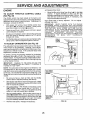
SERVICE AND ADJUSTMENTS
TO REPLACE
(See Fig. 24)
MOWER
BLADE
TO ADJUST
BELT
CLUTCH
(See
The electric clutch should provide years of service. The
clutch has a built-in brake that stops the pulley within 5
seconds. Eventually, the internal brake will wear which
may cause the mower blades to not engage, or, to not stop
as required. Adjustments should be made by your nearest
authorized service center/department.
Engage parking brake.
Remove m0wer drive belt (See'q'O REPLACE MOWER
DRIVE BELT" in this section of this manual),
Remove mower (See '*TO REMOVE MOWER" in this
section of this manual),
=
Remove four screws from R.H. mandrel cover and
remove cover. Unhook spring from bolt on mower
housing,
•
Carefully roll belt off R.H. mandrel pulley.
°
Remove belt from center mandrel pulley, idler pulley,
and L.H. mandrel pulley.
•
Remove any dirt or grass which may have accumulated around mandrels and entire upper deck surface.
-
Check secondary idler arm and idler to see that they
rotate freely.
•
Be sure spring is hooked in secondary idler arm and
sway-bar bracket.
o
Install new belt in lower groove of L.H. mandrel pulley,
idler pulley, and center mandrel pulley as shown.
-
Roll belt over R.H. mandrel pulley. Make sure belt is in
all grooves properly.
o
Reconnect spring to bolt in mower housing and reinstall R.H. mandrel cover.
o
Reinstall mower to tractor (See "INSTALL MOWER
AND DRIVE BELT s in the Assembly section of this
manual).
°
Reassemble mower drive belt (See "TO REPLACE
MOWER DRIVE BELT" in this section of this manual).
LR.
MANDREL
ATTACHMENT
Fig. 25)
Park the tractor on level surface.
=
DRIVE
MOWER
BLADE
DRIVE BELT
Make sure attachment clutch and ignition switches are
in "OFF" position.
•
NOTE: After installing a new electric clutch, run tractor at
full throttle and engage and disengage electric clutch 10
cycles to wear in clutch plate.
ROTOR
CLUTCH PLATE
BRAKE PLATE
NYLON LOCKNUT(3)
FIG. 25
CENTER
TO ADJUST
MANDREL
BRAKE (See Fig. 26)
Your tractor is equipped with an adjustable brake system
which is mounted on the right side of the transaxle.
IDLER
PULLEY
If tractor requires more than six (6) feet stepping distance
at high speed in highest gear, then brake must beadjusted.
R.H.
MANDREL
COVER
IDLER ARM
SPRING
SWAY-BAR
BRACKET
Adjust the three nylon Iocknuts until space between
clutch plate and rotor measures .012" at all three slot
locations cut in the side of brake plate,
SCREW
FIG. 24
22 ¸
=
Depress clutch/brake pedal and engage parking brake.
•
Measure distance between brake operating arm and
nut "A" on brake rod,
•
If distance is other than i -1/2", loosen jam nut and turn
nut "A" until distance becomes 1-1/2". Retighten jam
nut against nut "A".
•
Road test tractor for proper stopping distance as stated
above, Readjust if necessary, if stopping distance is
still greater than six (6) feet in highest gear, further
maintenance is necessary, Contact your nearest authorized service center/department.
SERVICE AND ADJUSTMENTS
TRANSAXLE
SHIFTER
LINKAGE
JUSTMENT (See Figs. 28 and 29)
WITH PARKING BRAKE "ENGAGED"
AND
AD-
The transaxle should be in neutral when the gear shift lever
is in the neutral (N) (lock gate) position. The adjustment is
preset at the factory; however, if adjustment is needed,
proceed as follows:
NUT "A"
JAM NUT
•
•
Make sure transaxle is in neutral (N).
Loosen two Iocknuts on tie rod.
•
Turn center rod until gearshift lever falls into neutral
lock gate on fender console.
•
Tighten Iocknuts securely.
"-OPE.AT,NG
AR,,
GEARSHIFT
LEVER
FIG. 26
LOCK GATE
TO REPLACE
(See
MOTION
DRIVE
BELT
Fig. 27)
Park the tractor on level surface. Engage parking brake.
For assistance, there is a belt installation guide decal on
bottom side of left footrest.
•
=
Remove mower (See "TO REMOVE MOWER" in this
section of this manual.)
Disconnect clutch wire harness.
°
Remove clutch Iocator.
,,
Remove upper belt keeper.
,,
,,
Remove belt from stationary idler and clutching idler.
Pull belt slack toward rear of tractor. Remove belt
upwards from transaxle pulley by deflecting belt keepers.
,,
FIG. 28
LOCKNUTS
CENTER
ROD
Pull belt toward front of tractor and remove downwards
from around electric clutch.
°
Install new belt by reversing above procedure.
IMPORTANT:
MAKE SURE UPPER BELT KEEPER IS
POSITIONED PROPERLY BETWEEN LOCATOR TABS
AND ELECTRIC CLUTCH WIRE CONNECTION
IS
[ E'ECTR,C-| CLUTCHING"Jrt-...,.,_
TIEROD
TRANSAXLE
CLUTCH'OCA
CLUTCH LOCATOR
'_,,,"_
_
LOCATOR TABS
UPPER IBELT
FiG. 29
TO ADJUST
__
| TRANSAXLE
II
...........................................
i 1 II-
section of this manual.
_
ing wheel and reassemble per instructions in the Assembly
FRONTWHEEL
CLUTCH
WIRE
HARNESS
FIG. 27
WHEEL ALIGNMENT
If steering wheel crossbars are not horizontal (left to right)
when wheels are positioned straight forward, remove steer-
,--J1--'=_
/ PUL'E'€--'--L[1 i
STEERING
TOE-IN/CAMBER
The front wheel toe-in and camber are not adjustable on
your tractor. If damage has occurred to affect the front
wheel toe-in or camber, contact your nearest authorized
service center/department.
23
SERVICE AND ADJUSTMENTS
TO REMOVE WHEEL
(See Fig. 30)
FOR REPAIRS
•
Block up axle securely.
•
Remove axle cover, retaining ring and washers to allow
wheel removal (rear wheel contains a square key - Do
not lose).
,,
Repair tire and reassemble.
,,
On rear wheels only: align grooves in rear wheel hub
and axle. Insert square key.
=
Replace washers and snap retaining ring securely in
axle groove.
-
Replace axle cover.
WASHERS
j
RETAINING
RING
FIG. 31
TO
t
AXLE COVER
SQUARE KEY
(REAR WHEEL ONLY')
HEADLIGHT
BULB
•
Raise hood.
•
Pull bulb holder out of the hole in the backside of the
grill.
•
Replace bulb in holder and push bulb holder securely
back into the hole in the backside of the grill.
•
Close hood.
INTERLOCKS
FIG. 30
TO START ENGINE
See Fig. 31)
REPLACE
AND RELAYS
Loose or damaged wiring may cause your tractor to run
poorly, stop running, or prevent it from starting.
•
WITH A WEAK BA'I-rERY
Check wiring. See electrical wiring diagram in the
Repair Parts section of this manual.
TO REPLACE
FUSE
Replace with 30 amp automotive-type plug-in fuse. The
fuse holder is located behind the dash.
CAUTION: Lead-acid batteries generate explosive gases. Keep sparks, flame
and smoking materials away from batteries.
Always wear eye protection
when around batteries.
TO REMOVE
HOOD
AND
GRILL
ASSEMBLY
(See Fig. 32)
If your battery is too weak to start the engine, it should be
recharged.
If "jumper cables" are used for emergency
starting, follow this procedure:
IMPORTANT: YOUR TRACTOR IS EQUIPPED WITH A
12 VOLT NEGATIVE GROUNDED SYSTEM. THE OTHER
VEHICLE MUST ALSO BE A 12 VOLT NEGATIVE
GROUNDED SYSTEM. DO NOT USE YOUR TRACTOR
BATTERY TO START OTHER VEHICLES.
=
Raise hood.
•
Unsnap headlight wire connector.
=
Stand in front of tractor. G rasp hood at sides, tilt toward
engine and lift off of tractor.
•
To replace, reverse above procedures.
TO ATTACH JUMPER CABLES •
•
"\
Connect each end of the RED cable to the POSITIVE
(+) terminal of each battery, taking care not to short
against chassis.
HOOD
\\
I
HEADLIGHT
WIRE
CONNECTOR
Connect one end of the BLACK cable to the NEGATIVE (-) terminal of fully charged battery.
...._onnect_the-other-end
of-the_BLACK cable__to_good.....
CHASSIS G ROU N D, away from fuel tank and battery.
TO REMOVE CABLES, REVERSE ORDER =
•
BLACK cable first from chassis and then from the fully
charged battery.
RED cable last from both batteries.
24
FIG. 32
SERVICE AND ADJUSTMENTS
ACCELERATION
ENGINE
•
TO ADJUST THRO'n'LE
(See Fig. 33)
CONTROL
CABLE
The throttle control has been preset at the factory and
adjustment should not be necessary. Check adjustment as
described below before loosening cable. If adjustment is
necessary, proceed as follows:
•
If holes are not aligned, loosen cable clamp screw and
align the holes by inserting a pencil or a 1/4" drill bit
through both holes.
•
Pull throttle cable up to remove slack and tighten cable
clamp screw. Remove alignment pencil or drill bit.
TO ADJUST
CARBURETOR
-
Move throttle control lever from slow (._b) to fast (,f_)
position.
If engine hesitates
or dies, turn idle fuel
adjusting needle eut (counterclockwise)
1/8 turn. Repeat test and continue to adjust,
if necessary,
until
engine accelerates
smoothly.
High speed stop is factory
damage may result.
adjusted.
Do
not adjust
CABLE
CLAMP
SCREW
(See Fig. 34)
The carburetor has been preset at the factory and adjustment should not be necessary. However, minor adjustment may be required tocompensate for differences in fuel,
temperature, altitude or load. If the carburetor does need
adjustment, proceed as follows:
SPEED_
BRACKET
In general, turning the adjusting needles in (clockwise)
decreases the supply of fuel to the engine giving a leaner
fuel/air mixture. Turning the adjusting needles out (counterclockwise) increases the supply of fuel to the engine giving
a richer fuel/air mixture.
THROTTLE
LEVER
IMPORTANT:
DAMAGE TO THE NEEDLES AND THE
SEATS IN CARBURETOR MAY RESULT IF NEEDLE IS
TURNED IN TOO TIGHT.
FIG. 33
NOTE: The carburetor on this engine is low emission. It is
equipped with an idle fuel adjusting needle with a limiter
cap, which allows some adjustment within the limits allowed
by the cap. Do not attempt to remove the limiter cap. The
limiter cap cannot be removed without breaking the adjusting
needle.
•
Be sure you have a dean air filter and the throttle
control cable is adjusted properly (see above).
•
Start engine and allow to warm for five minutes. Make
adjustments with engine running and shift/motion control
lever in neutral (N) position.
•
Idle speed settina - With throttle control lever in slow
(,_) position, engine should idle at 1750 RPM. If
engine idles too slow or fast, turn idle speed adjusting
screw in or out until correct idle is attained.
-
Idle fuel needle settina - With throttle control lever in
slow (,_b) position, turn idle fuel adjustment needle in
(clockwise) until engine begins to die and then turn out
(counterclockwise) until engine runs rough. Turn needle
to a point midway between those two positions.
.... _
Recheck idle speed.
Readjustif
-
IMPORTANT:
NEVER TAMPER
WiTH
THE ENGINE
GOVERNOR,
WHICH IS FACTORY SET FOR PROPER
ENGINE SPEED. OVERSPEEDINGTHEENGINEABOVE
THE
FACTORY
HiGH
SPEED
SETTING
CAN BE
DANGEROUS.
IF YOU THINK THE ENGINE-GOVERNED
-IIGH SPEED NEEDS ADJUSTING,
CONTACT
YOUR
4EAREST
AUTHORIZED
SERVICE
CENTER/
)EPARTMENT,
WHICH HAS PROPER EQUIPMENT
AND
--XPERIENCE
TO
MAKE
ANY
NECESSARY
\DJUSTMENTS.
With engine not running, move throttle control lever
from slow (.6_) to choke (1\0 position. Slowly move
lever from choke (1\1)to fast (,_) position.
Check to see if hole in throttle lever and hole in speed
control bracket are aligned.
=
TEST
IDLE SPEED
ADJUSTING
sc.Ew
,O,EPUE,/
--4
ADJUSTING
NEEDLE
FIG_ 34
necessary.
25
STORAGE
ENGINE
Immediately prepare your tractor for storage at the end of
the season or if the tractor will not be used for 30 days or
more.
FUEL SYSTEM
IMPORTANT:
IT iS IMPORTANT TO PREVENT GUM
DEPOSITS FROM FORMING IN ESSENTIAL FUEL
SYSTEM PARTS SUCH AS CARBU RETOR, FUEL FILTER,
FUEL HOSE, OR TANK DURING STORAGE.
ALSO,
EXPERIENCE INDICATES THAT ALCOHOL BLENDED
FUELS (CALLED GASOHOL OR USING ETHANOL OR
METHANOL) CAN ATTRACT MOISTURE WHICH LEADS
TO SEPARATION AND FORMATION OF ACIDS DURING
STORAGE.
AClD!C GAS CAN DAMAGE THE FUEL
SYSTEM OF AN ENGINE WHILE IN STORAGE.
•
Drain the fuel tank.
CAUTION: Never store the tractor with
gasoline in the tank inside a building
where fumes may reach an open flame
or spark. Allow the engine to cool
before storing in any enclosure.
TRACTOR
Remove mower from tractor for winter storage. When
mower is to be stored for a period of time, clean it thoroughiy, remove all dirt, grease, leaves, etc. Store in a
clean, dry area.
•
Clean entire tractor (See"CLEANING" in the Customer
Responsibilities section of this manual).
•
Inspect and replace belts, if necessary (See belt replacement instructions in the Service and Adjustments
section of this manual).
•
Lubricate as shown in the Customer Responsibilities
section of this manual.
-
Be sure that all nuts, bolts and screws are securely
fastened_ Inspect moving parts for damage, breakage
and wear. Replace if necessary.
*
Touch up al! rusted or chipped paint surfaces; sand
lightly before painting.
Fully charge the battery for storage.
•
After a period of time in storage, battery may require
recharging.
•
•
start the engine and let it run until the fuel lines and
carburetor are empty.
•
Never use engine or carburetor cleaner products in the
fuel tank or permanent damage may occur.
Use fresh fuel next season.
•
NOTE: Fuel stabilizer is an acceptable alternative in
minimizing the formation of fuel gum deposits during storage. Add stabilizer to gasoline in fuel tank or storage
container. Always follow the mix ratio found on stabilizer
container. Run engine at least 10 minutes after adding
stabilizer to allow the stabilizer to reach the carburetor. Do
not drain the gas tank and carburetor if using fuel stabilizer.
ENGINE OIL
Drain oil (with engine warm) and replace with clean engine
oil. (See "ENGINE" in the Customer Responsibilities
section of this manual).
BATTERY
•
•
CYLINDERS
To help prevent corrosion and power leakage during
long periods of storage, battery cables should be
disconnected and batterycleaned thoroughly (see'qO
CLEAN BATI-ERY AND TERMINALS" in the Customer Responsibilities section of this manual).
After cleaning, leave cables disconnected and place
cables where they cannot come in contact with battery
terminals.
•
Remove spark plug(s).
•
Pour one ounce of oil through spark plug hole(s) into
cylinder(s).
•
Turn ignitionkey to"START" position fora few seconds
to distribute oil,-
,
Replace with new spark plug(s).
OTHER
•
Be sure battery drain tube is securely attached.
,
Do not store gasoline from one season to another.
•
If battery is removed from tractor for storage, do not
store battery directly on concrete or damp surfaces.
°
Replace your gasoline can if your can starts to rust.
Rust and/or dirt in your gasoline will cause problems.
•
If possible, store your tractor indoors and cover it to
give protection from dust and dirt.
•
Cover your tractor with a suitable proteCtive cover that
does not retain moisture. Do not use plastic. Plastic
cannot breathe which allows condensation to form and
will cause your tractor to rust.
IMPORTANT: NEVER COVER TRACTOR WHILE ENGINE
AND EXHAUST AREAS ARE STILL WARM.
26
TROUBLESHOOTING
POINTS
E
CORRECTION
PROBLEM
CAUSE
Will not start
1.
Out of fuel.
1.
Fill fuel tank.
2.
3.
4.
5.
6,
7.
Engine not "CHOKED" properly.
Engine flooded.
Bad spark plug.
Dirty air filter.
Dirty fuel filter.
Waterin fuel.
2.
3.
4.
5.
6.
7.
8.
9.
10.
Loose or damaged wiring.
Carburetor out of adjustment.
Engine valves out of adjustment.
8.
9.
10.
See "TO START ENGINE" in Operation section.
Wait several minutes before affempting to start.
Replace spark plug.
Clean/replace air filter.
Replace fuel filter.
Drain fuel tank and carburetor, refill tank with fresh
gasoline and replace fuel filter.
Check all wiring.
Contact an authorized service center/department.
Contact an authorized service centeddepartment.
Hard to start
1.
2.
3.
4.
5.
6.
7.
8.
Dirty air filter.
Bad spark plug.
Weak or dead battery.
Dirty fuel filter.
Stale or dirty fuel.
Loose or damaged widng.
Carburetor out of adjustment.
Engine valves out of adjustment.
1.
2.
3.
4.
5.
6.
7.
8.
Clean/replace air filter.
Replace spark plug.
Recharge or replace battery.
Replace fuel filter.
Drain fuel tank and refill with fresh gasoline.
Check all wiring.
Contact an authorized service center/department.
Contact an authorized service center/department,
Engine will not turn over
1.
2.
3.
4.
Clutch/brake pedal not depressed.
Attachment clutch is engaged.
Weak or dead battery.
Blown fuse.
5.
6.
7.
8.
9.
Corroded battery terminals,
Looseor damaged widng.
Faulty ignition switch.
Faulty solenoid or starter.
Faulty operator presence switch(es).
1.
2.
3.
4.
5.
6.
7.
8.
9.
Depress clutch/brake pedal.
Disengage attachment clutch.
Recharge or replace baffery.
Replace fuse.
Clean battery terminals.
Check all wiring.
Check/replace ignition switch.
Check/replace solenoid or starter.
Contact an authorized service centeddepartment.
Engine clicks but will not
start
1.
2.
3.
4.
Weak or dead battery.
Corroded battery terminals.
Loose or damaged widng.
Faulty solenoid or starter.
1.
2.
3.
4.
Recharge or replace battery.
Clean battery terminals.
Check all wiring.
Check/replace solenoid or starter.
Loss of power
1.
2.
3.
4.
5.
6.
7.
8.
9.
Cuffing too much grass/too fast.
Throttle in "CHOKE" position.
Build-up of grass, leaves and trash under mower.
Dirtyair filter.
Low oil level/dirty oil.
Faulty spar k plug.
Dirty fuel filter.
Stale or dirty fuel.
Water in fuel.
1.
2.
3.
4.
5.
6.
7.
8.
9.
Set in "Higher Cut" position/reduce speed.
Adjust throttle control.
Clean underside of mower housing.
Clean/replace air filter.
Check oil level/change oil.
Clean and regap or change spark plug.
Replace fuel filter.
Drain fuel tank and refill with fresh gasoline.
Drain fuel tank and carburetor, refill tank with fresh
gasoline and replace fuel filter.
Connect and tighten spark plug wire.
Clean engine air screen/fins.
Clean/replace muffler.
Check all wiring.
Contact an authorized service center/department.
Contact an authorized service center/department.
10.
11.
12.
13.
14.
15.
Excessive vibration
..............................
1.
2.
3.
10.
11.
12.
!3.
14.
15,
Spark plug wire loose.
Dirty engine air screen/fins.
Dirty/clogged muffler.
Loose or damaged wiring.
Carburetor out of adjustment.
Engine valves out of adjustment.
Worn, bent or loose blade.
B_n_ hi@de,mandrel .............................
Loose/damaged part(s).
1.
2.
3.
27
Replace blade. Tighten blade bolt.
Replace blade mandrel ...........
Tighten loose part(s). Replace damaged
parts.
TROUBLESHOOTING
PROBLEM
CAUSE
POINTS
CORREC_ON
=
Engine continues to run
when operator leaves seat
with attachment clutch
1.
Faulty operator-safety presence control system.
1,
Check wiring, switches and connections,
if not
corrected_ contact an authorized service center/
department.
1.
2.
Worn, bent or loose blade.
Mower deck not level.
1.
2.
Replace blade. Tighten blade bolt.
Level mower deck,
3.
4.
Buildup of grass, leaves, and trash under mower.
Bent blade mandrel.
5.
Clogged mower deck vent holes from buildup of
grass, leaves, and trash around mandrels.
3,
4,
5.
Clean underside of mower housing.
Repla._e blade mandrel.
Clean around mandrels to open vent holes.
engaged
Poor cut- uneven
Mower blades will not
rotate
Poor grass discharge
1.
Obstruction
2.
3,
4.
Worn/damaged mower drive belt,
Frozen idler pulley.
Frozen blade mandrel,
1.
2.
3.
4.
Remove
Replace
Replace
Replace
1.
2.
3.
4.
Engine speed too slow.
Travel speed too fast.
Wet grass.
Mower deck not level,
!.
2.
3,
4.
Place throttle control in "FAST" position.
Shitt to slower speed,
Allow grass to dry before mowing.
Level mower deck,
5.
6.
7.
8.
9.
10.
11,
Headlight(s) not working
(if so equipped)
Battery will not charge
Engine "backfires"
when turning engine
"OFF"
in clutch mechanism.
Low/uneven tire air" pressure.
Worn, bent or loose blade.
Buildup of grass, leaves and trash under mower.
Mower drive belt worn,
Blades improperly installed.
Improper blades used.
Clogged mower deck vent holes from buildup of
grass, leaveS, and trash around mandrels,
5.
6.
7.
8.
9,
10.
11.
Obstruction.
mower drive belt.
idler pulley.
blade mandrel.
Check tires for proper air pressure.
Replace/sharpen blade. Tighten blade bolt.
Clean underside of mower housing.
Replace mower drive belt,
Reinstall blades sharp edge down.
Replace with blades listed in this manual.
Clean around mandrels to open vent holes.
1,
Switch is "OFF".
1.
Turn switch "ON".
2.
3.
4.
5.
Bulb(s) burned out.
Faultylight switch.
Looseor damaged widng,
Blown fuse.
2.
3.
Replace bulb(s).
Check!replace light switch.
4.
5,
Checkwidng and connections,
Replace fuse.
1.
2.
Bad battery cell(s).
Poor cable connections.
1.
2.
Replace battery.
Check!clean all connections.
3.
4.
Faulty regulator (it so equipped),
Faulty alternator.
3.
4,
Replace regulator.
Replace alternat0r.
1.
Engine throttle control not set at "SLOW"
position for 30 seconds before stopping engine.
1.
Move throttle control to "SLOW" position and allow
to idle for 30 Seconds before stopping engine.
28
TRACTOR
- - MODEL
NUMBER
917.256600
SCHEMATIC
BLACK
RED
BATTERY
I
oq o
RED
I
II
RED
FUSE 30 AMP.
AMMETER
I
STARTER
I
BLAOK
i
WH_E
I
I
L
)G
L(
J
CLUTCH / BRAKE
(PEDAL UP)
_
.....
J
SEAT SWITCH
(NOT OCCUPIED)
WHITE
BLACK
I
i
I
I
I
q
t
I
GROUNDING
CONNECTOR
O
BLACK
IGNITION
UNIT
I
SPARK
PLUG
1
I
AFTER
_.__(_
I
FIRE
SOLENOID
CHARGING
SYSTEM OUTPUT
3 AMP DC @ 3600 RPM
28 VOLTS AC MIN. @ 3600 RPM
(CHARGING SYSTEM DISCONNECTED)
aE_
LIGHTING
SYSTEM
I
NOTE
OUTPUT
DIODE
I ALTERNATOR
YOUR TRACTOR IS
_AMPAC
__
14_
EQUIPPED WITH A SPECIAL
I_
_
J
ALTERNATOR SYSTEM.
I_
" 14VOLTS
AOMIN.@36_ RPM
(L}GHTS
OFF)
THE LIGHTS ARE NOT
15
HEADLIGHTS
CONNECTED TO THE
! ',-- ....
_-'
_
....
BAKERY, BUT HAVE THEIR
_
__
OWN ELECTRICAL SOURCE
,v
_'_I
_T
_-)
T_
"
BECAUSE OF THIS, THE
HEADLIGHT
I
_
I
BRIGHTNESS OF THE LIGHTS
SWITCH' '
_5
IGNITION SWITCH
WILL CHANGE WITH ENGINE
(OFF)
_ '-.-.J/
POSITION
CIRCUIT
SPEED. AT IDLE THE LIGHTS
WILL DIM. AS THE ENGINE IS
WIRING INSULATED CLIPS
OFF
M + G
SPEEDED UP, THE LIGHTS
ON
B+L
WILL BECOME THEIR BRIGHTEST.
NOTE: IF WIRING INSULATED
START
B+ S+ L
CLIPS WERE REMOVED FOR
...................
SERVICING OF UNIT; _EY
....
A
W
NON,REMOVABLE
REMOVABLE
SHOULD BE REPLACED TO
CONNECTIONS
CONNECTIONS
PROPERLY SECURE YOUR WIRING.
29
REPAIR PARTS
TRACTOR
- = MODEL
NUMBER
917.256600
ELECTRICAL
,r
\
80
40
42
36
35
'
_13-
39
\
26
\
34
\
\,
\
20
51
5O
29
3O
REPAIR PARTS
TRACTOR
- = MODEL
NUMBER
917.256600
ELECTRICAL
KEY
NO.
PART
NO.
1
2
3
4
6
7
8
9
10
11
12
19
20
21
22
24
25
26
28
29
30
31
32
33
34
35
36
39
40
41
42
43
44
45
49
50
51
52
55
70
80
146140
74760412
STD551025
STD551125
STD541025
7697J
7603J
109596X
145211
145209
145769
STD551125
73350400
136850
4152J
146136
146148
108824X
145491
121305X
144921
140400
141226
140403
110712X
108236X
STD601005
109553X
149170
71110408
131563
145873
73640400
121433X
STD551262
146283
140405
141940
17490508
142621
146685
NOTE:
DESCRIPTION
Battery
Bolt, Hex 1/4-20 UNC x 3/4
Washer
Washer
Nut
Tube, Plastic
Tray, Battery
Clamp, Hose
Bolt, Btr. Frt 1/4-20 x7.5
Hotddown Btr. Dash
Nut, Push Nylon 1/4" Battery
Washer, Lock
Nut, Hex, Jam 1/4-20 UNC
Harness, Light Socket W/4152J
Bulb, Light
Cable Battery
Cable, Battery
Fuse
Cable, Ground
Switch, Plunger
Switch, Ignition
Nut, Ignition
Cover, Ignition Switch
Key,, ignition
Switch, Light
Bracket, Switch
Screw
Switch, InterLock
Harness, !gnition
Bolt BIk Fin. Hex 1/4-20 x 1/2
Cover, Terminal
Solenoid
Nut, Keps BIk Hex 1/4-20 UNC
Ammeter Rectangular 6Amp
Washer Lock Int. Tooth 5/8
Switch PTO 3 Pot Red Delta
Ring Retainer PTO
Wire Loop
Screw Thdrol 5/16-18 x 1/2 TYT
Harness Engine Koh Cmd-L Dual
Harness Clutch Ev×
All component dimensions given in U.S. inches
1 inch = 25.4 mm
31
REPAIR PARTS
TRACTOR
CHASSIS
= = MODEL
NUMBER
917.256600
AND ENCLOSURES
30
6
29
17
8
I
0
36
26
25
47
28
26
122
31
44
9O
125
71
66
124
115
3
117
114
123
73
86
114
26
33
10
3
38
34
39
32
117
REPAIR PARTS
TRACTOR
CHASSIS
- - MODEL NUMBER
917.256600
AND ENCLOSURES
KEY
NO.
PART
NO.
DESCRIPTION
1 145501
Chassis
2 140356
Drawbar
3 17490612
Screw, Thdrol. 3/8-16 x 3/4 Type "iT
6 145206
Saddle
8 126471X
Clip, Fuel Line
9 145203
Dash, Plastic
10 STD533710
Bolt, Carriage 3/8-16 x 1
11 145218
Panel, Dash, LH
13 145217
Panel, Dash, RH
14 17490608
Screw, Thdrol. 3/8-16 x 1/2 Type -IT
17 136673X558
Hood Assembly
24 STD523710
Bolt
25 19131312
Washer 13/32 x 13/16 x 12 Gauge
26 STD541437
Nut
28 136373X428
Grill
29 136374
Lens, Bar, Clear
30 140002X558
Fender
31 137113
Bracket Assembly, Fender
33 145244X558
Footrest, LH
34 145243X558
Footrest, RH
35 STD533707
Bolt
36 108067X
Nut, Pal
38 139886
Bracket Assembly, Pivot, LH
39 139887
Bracket Assembly, Pivot, RH
44 140675
Fender Strap
47 105531X
Nut, Push, Nylon
50
137304
Rod, Support Hood
59 110436X
Bushing, Snap, Split
64 150272
Dash, Lower
66 143485X012
Plate, Dash
71 73640400
Nut
73 17580408
Screw -rap Tite 1/4-20 x 1/2
86
136670X558
Panel Assembly, RH
87 136671X558
Panel Assembly, LH
90 STD551025
Washer 17/64
114 145349
Bracket, Support, Dash
115 121794X
Cover, Access
117 144283
Washer Serrated Disk 13/32 x 1
119 19092016
Washer 9/32 x 1-1/4 x 16 Ga.
120 137271
Rivet, Ratchet, Female
121 137269
Washer, Nylon
122 137270
Rivet, Rachet, Male
123 136814
Bracket Assembly, Front Pivot Hinge, LH
124 136813
Bracket Assembly, Front Pivot Hinge, RH
125 74180412
Screw, Machine 1/4-20 x 3/4
-5479J
Plug Btn BIk .359 Dia Ch/Inf
NOTE: All component dimensions given in U.S. inches
1 inch = 25.4 mm
33
REPAIR PARTS
DRIVE
TRACTOR
. . MODEL NUMBER
1B
917.256600
38 _42
6
62
35
36
34
37
53
26
27
34
REPAIR PARTS
TRACTOR
= = MODEL NUMBER 917.256600
DRIVE
KEY
NO,
PART
NO.
145607
2 146682
3 123666X
4 STD582075
5 121520X
6 17490512
_9
1_
11
12
13
14
15
16
18
19
2O
21
22
23
24
25
26
27
28
29
30
31
32
33
34
35
36
37
38
39
40
41
42
STD561-210
105701X
19151216
74550412
STD551125
74490544
STD541431
STD523710
STD541437
71170768
106933X
130804
140275
STD541237
106888X
STD551037
STD561210
145204
124236X
130807
127275X
STD523107
STD533107
149001
120183X
STD551062
STD571810
123674X
STD523727
4470J
109070X
19131312
KEY
NO.
DESCRIPTION
Transaxle, Dana, Model Number
436O-97
Spring, Brake Return
Pulley, Transaxle
Ring, Retainer
Strap, Torque
Screw, Hex, Washer, Thread
Rolling 5/16-18 x 3/4
Rod, Shifter
Clutch, Electric
Pin, Cotter 1/8 x 1
Washer, Shift Plate
Washer 15/32 x 3/4 x 16 Ga.
Bolt 1/4-28 UNF Gr. 8 w/Patch
Washer Lock
Bolt Hex FIghd 5/16-18 Gr. 5
Nut Lock Hx W/Ins 5/16-18 UNC
Bolt
Locknut 3/8-16
Bolt, Hex 7/16-20 x 4-1/4
Knob
Rod, Brake
Bracket Assembly, Clutch
Nut, Hex Jam 3/8-16
Spring, Rod, Brake
Washer 13/32 x 13/16 x 16 Gauge
Pin, Cotter 1/8 x 3/4
Rod, Brake, Park
Cap, Plunger
Bracket, Transaxle, L.H.
Keeper, Belt, Transaxle, L.H.
Bolt Hex Hd 5/16-18 UNC x 3/4
Bolt,Carriage 5/16-18 x 3/4
Shaft, Foot Pedal
Bearing Nylon
Washer 21/32 x 1 x 16 Gauge
Pin,Roll 3/16 x 1
Idler, Flat
Bolt, Hex 3/8-16 x 2-3/4
Spacer
Keeper, Belt
Washer 13/32 x 13/16 x 12 Gauge
44
45
46
47
48
49
50
51
52
53
54
55
56
57
58
59
60
61
PART
NO.
105706X
!10812X
12000039
127783
123789X
123205X
STD523715
STD541437
STD541431
105710X
2751R
105709X
STD523712
130801
127274X
140312
121218X
17490612
DESCRIPTION
Bearing
Washer, Hardened
Ring, Clip
Pulley, idler
Arm, Idler
Retainer, Belt
Bolt, Hex 3/8-16 x 1-1/2
Nut, Crownlock 3/8-16
Nut, Lock Hex w/Ins 5/16-18
Link, Clutch
Clip Line Fuel 13/32 Mtg Hole
Spring, Return, Clutch
Bolt, Hex 3/8-16 x 1-1/4
V-Belt, Drive
Keeper, Belt, Transaxle, R.H.
Retainer, Belt
Keeper, Belt, Engine, LH
Screw, Hex Washer Head, Thd.,
Roll. 3/8-16 x 3/4
Cover, Foot Pedal
Pulley, Clutch Electric Evx
Washer, Lock Hvy Hlcl Spr 7/16
Belt Keeper, Engine
Spacer, Split
Washer 25/32 x 1-1/4 x 16 Ga.
E-Ring
Key Square
Washer 25/32 x 1-5J'8x 16 Ga.
Shift Arm
Shaft, Assembly, Shifter
Spring, Torsion
Washer 17/32 x 3/4 x 16 Gauge
Rod, Tie
Nut Lock Center 1/4-28
Bushing, Rod, Steering
Washer 21/32 x 1-1/4 x 16 Gauge
Ring, Klip
Console, 6 Speed
Nut, Washer Head, Self-Thread 1/4
Washer 11/32 x 3/4 x 14 Ga.
62 8883R
63 145868
65 STD551143
68 105730X
74 109502X
75 121749X
76 STD581075
77 123583X
78 121748X
80 131487
81 136933
82 123782X
83 19171216
84 132183
85 150360
86 71208
87 19212016
88 12000008
89 139991
90 124346X
114 19111214
NOTE: All component dimensions given in U.S. inches
1 inch = 25.4 mm
35
REPAIR PARTS
TRACTOR
STEERING
- - MODEL NUMBER
917.256600
ASSEMBLY
62
_I
47
14
16
/
43
11
12
;43
8
10
36
REPAIR PARTS
TRACTOR
STEERING
-- MODEL NUMBER 917.256600
ASSEMBLY
KEY
NO.
PART
NO.
1
2
3
4
5
6
7
8
9
10
11
12
13
14
15
121472X
142033
135227
135228
6266H
121748X
19272016
12000029
3366R
130468
STD551137
73610600
110438X
74011056
73901000
16 132624
17 128758
18 57079
19 124035X
2O 126684X
21 STD551125
22 71100410
23 1275O1
24 109816X
25 124036X
26 126847X
27 136874
28 19131416
29 17490612
3O STD561210
32 130465
36 145207
37 17541008
38 126805X
39 100712K
40 STD541350
41 100711L
42 140216
43 121749X
46 121232X
47 6855M
62 149682
NOTE:
DESCRiPTiON
Steering Wheel
Axle Assembly, Front
Spindle Assembly, LH
Spindle Assembly, RH
Bearing, Race, Thrust, Hardened
Washer 25/32 x 1-5/8 x 16 Gauge
Washer 27/32 x 1-1/4 x 16 Gauge
Ring, Klip
Bearing
Link, Drag
Washer, Lock
Nut, Hex, Fin. 3/8-24 UNF
Spacer, Bearing, Front Axle
Bolt, Hex 5/8-11 UNC x 3-1/2
Locknut, Hex, Jam, w/Washer insert
5/8-11 UNC
Pin, Axle, Large 5/8 x 1.55/1.54
Shaft Assembly, Steering
Washer, Thrust .515 x .750 × .033
Support, Shaft
Washer, Shim 1/4 x 5/8 x .062
Washer
Screw, Cap Sckt Hd Phos & Oil
Shaft Assembly, Pittman
Nyliner, Snap-In
Bracket, Steering
Bushing Link Drag BIk LR
Gear, Sector
Washer 13/32 x 7/8 x 16 Ga.
Screw, Thdrol 3/8-16 x 3/4
Pin Cotter 1/8 x 3/4 Cad
Tie Rod
Bushing, Steering
Screw SLFTP #10-24 x 1/2 TT-B
insert, Cap, Steering Wheel
Washer .53 x 2.25 x .160
Nut
Adapter, Steering Wheel
Column, Steering
Washer 25/32 x 1-1/4 x 16 Gauge
Cap, Spindle
Fitting, Grease
Kit, Steering Assembly
Alt component dimensions given in U.S. inches
1 inch = 25.4 mm
.,
37
REPAIR PARTS
TRACTOR
- - MODEL NUMBER 917.256600
ENGINE
77
32
31
©
O
/
33
37
39
4O
41
29
33
!
\
OPTIONAL
23
EQUIPMENT
Spark Arrester
38
REPAIR PARTS
TRACTOR
- - MODEL
NUMBER
917.256600
ENGINE
KEY
NO.
PART
NO.
1
2
134265
17720410
3
151063
4
14
15
16
23
24
29
31
32
33
34
37
38
137350
13280328
13200300
STD551231
128953
STD601005
137180
151346
151296
123487X
106082X
8543R
.......
39
40
41
62
77
79
80
81
109227X
3645J
139277
STD551131
STD551031
M740108025
STD523105
128861
NOTE:
DESCRIPTION
Control, Throttle
Screw, Hex Head, Thread Cutting
1/4-20 x 5/8
Engine, Kohler Model No.
CV15S-PS41525
Muffler, LT Koh 12.5/15 HP
Nipple, Pipe
Elbow, Standard 90 °, 3/8-18 NPT
Washer, Lock
Shield, Heat
Screw
Arrester, Spark
Tank, Fuel
Cap Assembly, Fuel
Clamp, Hose
Spacer, Pad
Line, Fuel
Plug, Oil Drain
(Order From Engine Manufacturer)
Spacer Pad
Bushing
Stem, Fuel Tank
Washer Lock Hvy Helical Spr 5/16
Washer 5/16 x 3/4 x 16 Ga.
Bolt Hex
Bolt Hex Hd 5/16-18 UNC x 1/2
Nut Flange 1/4-20 Starter Nut
All component dimensions given in U.S. inches
1 inch = 25.4 mm
39
REPAIR PARTS
TRACTOR
° - MODEL NUMBER 917.256600
SEAT ASSEMBLY
17
KEY
NO.
1
2
5
6
7
10
11
12
13
1_,
15
PART
NO.
140123
140551
145006
STD541437
124181X
140552
120068X
121246X
121248X
72050411 .......
134300
12
DESCRIPTION
KEY
NO.
Seat
Bracket, Pivot, Seat
Clip Push-In
Nut
Spring, Seat
Pan, Seat
Knob, Seat
Bracket, Switch Mounting
Bushing, Snap, Nylon
Bblt;Carriag6
1/4-20 x1-378
Spacer, Split
16 121250X
Spring
17 123976X
Nut, Flangelock 1/4 Grade 5
18 124238X
Cap, Spring, Seat
21 139888
Bolt, Shoulder 5/16-18 UNC
Nut
22 STD541431
24 19171912
Washer 17/32 x 1-3/16 x 12 Gauge
25 127018X
Bolt, Shoulder 5/16-18 x .62
Screw Thdrol. 3/8-16 x 1/2
27 17490608
Bolt 5/16-18 UNC x 3/4 W/seres
28 150176
SlOTE: All component dimensions given in U.S. inches
1 inch = 25.4 mm
4O
PART
NO.
DESCRIPTION
REPAIR PARTS
TRACTOR
- - MODEL NUMBER 917.256600
DECALS
13
18
6
3 16 7
8
8167
5
4
21
10
.\
19
1!
12
23
1
15
17
14
23
KEY
NO.
1
2
3
4
5
6
7
8
9
10
11
12
13
PART
NO.
138955
150333
146705
146706
151400
133644
138048
142241
146709
137537
4900J
146046
151452
WHEELS
KEY
NO.
DESCRIPTION
Decal,
Decal,
Decal
Deca
Decal
Decal
Decal
Decal
Decal
Decal
Decal
Decal
Decal
14
15
16
17
18
19
20
21
23
------
Operating Instruction
Cap Cnsmr Help Line Srs
Hood, Craftsman, RH
Hood, Craftsman, LH
Grille
Maintenance
Side Panel
Side Panel
Fender, Craftsman
Caution
Crutch/Brake
V-Belt Drive Schematic
Chassis, 6 Speed/46"
PART
NO.
139346
12-113-55
1517O8
151302
146710
138047
149516
140837
106202X
138311
145247
145245
152032
152033
DESCRIPTION
Decal, V-Belt Schematic
Decal Kohl 15.5 Crnd-L Sears
Decal Ins. Hood
Decal, Deck Mower EZ3 Polo
Decal, Insert Strg
Decal, Battery
Decal, Btry Dngr/Psn Eng Acme
Decal Brake Parking Saddle
Reflector, Taillight
Decal, Handle Lift Height Adj.
Fastener Pop-In Footrest
Decal, Pad Footrest
Manual, Owner's (Eng)
Manual, Owners (Span)
& TIRES
KEY
NO.
5,8
PART
NO.
1 59192
2 65139
3 106222X
4 59904
5 106732X427
6 278H
7 9040H
8 !06108X42Z
9 122082X
10 7152J
11 104757X
- - 144334
4,10
7
11
NOTE:
41
DESCRIPTION
Cap, Valve, Tire
Stem, Valve
Tire, Front
Tube, Front (Service Item Only)
Rim Assembly, Front
Fitting, Grease (Front Wheel Only)
Bearing, Flange (Front Wheel Only)
Rim Assembly, Bear .........
Tire, Rear
Tube, Rear (Service Item Only)
Cap, Axle
Sealant, Tire (10 oz. Tube)
All component dimensions
1 inch = 25.4 mm
given in U.S. inches
REPAIR PARTS
TRACTOR
MOWER
- - MODEL NUMBER
917.256600
LIFT
8
<!
41
I
7
I
22
5
37
21
30
3
5
13
19
13
2O
15
19
42
REPAIR PARTS
TRACTOR
MOWER
-- MODEL NUMBER
917,256600
LIFT
KEY
NO.
PART
NO,
1
2
3
4
5
6
7
8
10
11
12
13
15
16
17
18
19
20
21
22
23
24
25
26
27
28
29
30
31
32
35
36
37
38
40
41
136971
136968
138284
S'1-D581062
19211621
120183X
125631X
122365X
122512X
139865
139866
STD624008
127218
73350800
130171
STD541450
139868
STD624008
19151216
12000037
110807X
STD551037
137150
STD560907
137167
STD541237
138057
110810X
140302
73540600
120529X
123933X505
123935X
17490512
19112410
123934X
NOTE:
DESCRIPTION
Wire Asm., Inner w/plunger
Shaft Asm Lift
Pin Groove
E Ring #5133-62
Washer 21/32XlX21Ga
Bearing Nylon
Grip Handle Fluted
Button, Plunger
Spring Cprsn
Link Lift Lh
Link Lift Rh
Retainer Spdng
Link Front
Nut Jam Hex 1/2-13 Unc
Trunnion BIk Zinc
Nut Lock WNVsh 1/2-13 Unc
Arm Suspension Rear
Spring Retainer
Washer 15/32 X 3/4 X 16 Ga
Ring Klip #T5304-37
Nut Special
Washer 13/32 X 5/8 X 16 Ga
Spring Compression Inf Hgt
Pin Cotter 3/32 x 1/2
Rod Adjust Lift
Nut Hex Jam 3/8-16 Uric
Knob Infinite 3/8-16 Unc Black
Trunnion Dp Stop Dbl Thds Pit
Bearing Pvt. Lift Spherical
Nut, Crownlock 3/8-24
Washer, Nylon .44 x .75 x .032
Pointer, Height Indicator
Plug, Hole
Screw Thdrol 5/16-18 x 3/4
Washer 11/32 x 1-1/2 x 10 Gauge
Scale, Height Indicator
All component dimensions given in U.S. inches
1 inch = 25.4 mm
43
REPAIR PARTS
TRACTOR
MOWER
- - MODEL
NUMBER
917.256600
DECK
46
49
46
41
45
47
116
117
119
21
20
1O5
8
104
101
44
106
REPAIR PARTS
TRACTOR
MOWER
-= MODEL NUMBER 917.256600
DECK
KEY
NO.
1
3
5
6
8
9
10
PART
NO.
145008
138457
STD624008
130832
850857
STD551137
140296
11
12
13
145708
129895
137553
14
15
16
18
19
20
21
22
23
24
25
26
27
28
29
30
31
32
33
34
35
36
137152
110485X
140329
STD533106
132827
145055
STD541431
134753
131267
105304X
149287
110452X
145325
19111016
131491
138776
129963
129207
137266
144945
17490628
STD551037
DESCRIPTION
Deck Asm., Mower 46"
Bracket Asm., Sway Bar
Retainer Spring
Arm, Suspension, Rear (Sway Bar)
Bolt, Patched 3/8-24 x 1-1/4 Gr. 8
Washer, Lock Hvy., Unplated 3/8
Washer, Hard Blade, Mower
Vented
Blade, 46" Mower Deck
Bearing, Bail, Mandrel #6204
Shaft Asm. w/Lower Bearing
(Includes Key No. 12)
Housing, Mandrel
Bearing, Bail, Mandrel
Stripper, Mower Round
Bolt, Carriage 5/16-18 x 5/8
Bolt, Hex Head, Shoulder 5/16-18
Baffle, Vortex Mower 46"
Nut, Crownlock 5/16-18 UNC
Stiffiner, Bracket
Bracket, Deflector
Cap, Sleeve
Spring, Torsion, Deflector
Nut, Push
Shield, Deflector Mower
Washer 11/32 x 5/8 x 16 Ga.
Rod, Hinge
Screw, Hex Head, Thdroll
Washer, Spacer Mower Vented
Pulley, Mandrel
Nut, Fig. Top Lock Cntr. 9/16
Anchor, Spring Deck 46"
Screw, Thdroll 3/8-16 x 1-3/4 Tytt
Washer 13/32 x 13/16 x 16 Ga.
KEY
NO,
PART
NO.
37
38
39
40
41
42
43
44
45
46
47
48
49
50
101
102
103
104
105
106
116
117
118
119
126
127
--
131494
137554
144917
137273
17490620
122052X
144949
133943
145059
137729
144959
148763
STD541437
72110612
145579
71161010
STD551110
STD551025
130758
2029J
137644
133957
STD541437
STD551037
144948
146763
143651
--
147401
NOTE:
45
DESCRIPTION
Pulley, Idler, Flat
Keeper, Belt, Idler
Pulley, Idler, Driven
Spring, Secondary 44/46/50 Vent
Screw, Thdroll 3/8-16 x 1-1/4 Tytt
Spacer, Retainer
Arm, Idler Secondary
Washer, Hardened
Cover, Mandrel Deck
Screw, Thdroll. 1/4-20 x 5/8
V-Belt, Mower, Secondary
V-Belt, Mower, Primary
Nut, Crownlock 3/8-16 UNC
Bolt, Carriage 3/8-16 x 1-1/2 Gr. 5
Cover, Mulching
Screw
Washer, Lock #10
Washer
Latch Asm. Bagger
Nut, Weld
Bolt, Shoulder
Gauge Wheel, Wide
Nut, Centerlock 3/8-16 UNC
Washer 3/8 x 7/8 x 14 Ga.
Arm, Idler, Primary Deck 46"
Pulley, Idler, V-Groove Dim. 4.25
Mandrel Asm (Includes Key nos.
8-10, 12-15, 31 and 33)
Deck Complete (Std. Deck-Order
separately mulcher plate and gauge
wheel components Key Nos. 101106 and 116-118)
All component dimensions given in U.S. inches
1 inch = 25.4 mm
REPAIR PARTS
TRACTOR
DANA TRANSAXLE
- MODEL
- - MODEL NUMBER
NUMBER
917,256600
4360-97
2O
21
22
I I
I/
2
24
31
26
32
27
33
36
34
35
6
37
52
lg
40
53
41
42
54
17
44
46
55
12
,6
47
57
48
49
59
50
i6 55
51
59
63
64
43*52
65
68
69
67
/
66
46
7O
REPAIR PARTS
TRACTOR
DANA TRANSAXLE
KEY PART
NO. NO.
1
2
3
4
5
6
7
8
9
10
11
12
13
14
15
16
17
18
19
20
21
22
23
24
25
26
27
28
29
30
31
32
33
34
35
36
37
38
132671
2274J
134400
105904X
105905X
134788
134399
120951X
148266
2225J
134793
143679
120415X
142674
106846X
106095X
105909X
105910X
105911X
142675
138246
138238
148268
143673
2244J
105916X
120470X
110070X
142677
142681
124644X
108980X
120406X
134796
105925X
2232J
108978X
110079X
= MODEL
- - MODEL
NUMBER
NUMBER
917.256600
4360-97
KEY PART
NO. NO.
DESCRIPTION
Housing, Upper
Screw, Tapping, Large
1/4-20 x .734
Ball, Detent
Spring, Detent
Screw, Set
Kit, Shifter Assembly
Boot, Shifter
Puck, Friction
Bearing, Flange
Ring, Retaining
Assembly, Kit, Shim, .625 Shaft
Gear, Spur, 15 Teeth (2_.,\)
Washer, Plain .632 x 1.38 x .046
Key, Woodruff, #9
Assembly, Kit, Input Shaft
Pinion, Bevel, 14 Teeth
Ring, Retaining
Chain, 24 Pitches
Bearing, Flange
Gear, Spur, 14Teeth
Collar, Clutch
Assembly, Kit, Clutch Keys
Bearing, Flange
Shaft, Intermediate
Key, Woodruff, #61
Ring, Retaining
Sprocket, 18 Teeth (Reverse)
Spacer
Gear, Spur, 37 Teeth (1,,)
Gear, Spur, 35 Teeth (2.,)
Gear, Spur, 30 Teeth (3-)
Gear, Spur, 25 Teeth (4,_)
Gear, Spur, 22 Teeth (5,_)
Gear, Spur, 19 Teeth (6,_)
Washer, Plain .640 x 1.37 x .061
Washer, Plain .632 x 1.00 x .026
Spacer .630 x 1.00 x .169
Assembly, Gear, Combination,
12 Teeth and 35 Teeth
39
40
41
42
43
44
45
124639X
120472X
105928X
106605X
134394
120473X
106596X
46
47
48
49
50
51
52
53
54
55
56
57
58
59
60
61
62
63
64
65
66
67
68
69
70
71
72
73
142678
120407X
106589X
120408X
105937X
2226J
134401
2264J
120474X
110081X
105941X
110071X
120952X
106592X
120475X
142680
120961X
7294J
108989X
120953X
120954X
134799
138244
108996X
120956X
73810500
148269
120416X
DESCRIPTION
Shaft, Idler
Spacer .633 x .87 x .755
Sprocket, 9 Teeth (Reverse)
Gear, Bevel, 42 Teeth
Assembly, Kit, Shim, .750 Shaft
Shaft, Drive
Screw, Tapping, Large
5/16-18 x 1.44
Gear, Spur, 12 Teeth (1.,)
Gear, Spur, 20 Teeth (3-)
Gear, Spur, 25 Teeth (4,,)
Gear, Spur, 28 Teeth (5,,)
Gear, Spur, 31 Teeth (64)
Washer, Plain .632 x 1.00 x .060
Washer, Neoprene
Washer, Plain .758 x 1.25 x .031
Axle, L.H.
Gear, Miter, 15 Teeth
Ring, Retaining
Gear, Spur, 32 Teeth
Shaft, Cross
Gear, Miter, 15 Teeth
Axle, R.H.
Housing, Lower
Puck, Friction
Disc, Brake
Spacer
Jaw, Brake
Pin, Dowel
Screw, Tapping 5/16-18 x 2.25
Lever, Actuating
Washer, Plain .321 x 1.00 x .055
Bracket, Anti-Rotation
Locknut 5/16-24
Seal, Oil
Grease
NOTE: All component dimensions given in U.S. inches
1 inch = 25.4 mm
47
REPAIR PARTS
TRACTOR
KOHLER
ENGINE - MODEL
AIR INTAKE
-- MODEL
NUMBER
I
NUMBER
917.256600
CV15S, TYPE NUMBER
BLOWER
PS41525
H O_
14
m2
m
3
--e
__
ENGINE
CONTROLS
J
10
9
//
CRANKSHAFT
I
6 --5
EXHAUST
!
/ ......
6
48
REPAIR PARTS
TRACTOR
KOHLER
ENGINE
- - MODEL NUMBER 917.256600
- MODEL NUMBER
CV15S, TYPE NUMBER
AIR INTAKE
KEY
NO.
PART
NO.
1
2
3
4
5
6
7
8
9
1012
25 341 02
12 096 24
12 083 08
1210001
X-25-63
1231304
1208305
12 072 03
1208601
094 12
11
12041 02
NOT ILLUSTRATED
-12 11353
ENGINE CONTROLS
KEY
NO.
DESCRIPTION
Knob, Air Cleaner Cover
Cover, Air Cleaner
Precleaner Element
Wing Nut
Washer, Plain 1/4
Grommet
Element, Air Cleaner (Includes #6)
Stud, Mounting Plate
Screw, Mounting Plate Stud (2)
Base, Air Cleaner
(includes Key Numbers 9 and 10)
Gasket, Air Cleaner
Decal, Air Cleaner
CRANKSHAFT
KEY PART
NO, NO.
1
2
12 014 37
12 139 01
PS41525
PART
NO.
1
2
3
4
5
12 079 07
1223701
SM-0645016
SM-0545016
12 536 01
6
7
8
9
10
11
12
M-0443020
SM-0443025
1208911
12 089 23
12O8924
M-0641060
SM-0642025
13
14
15
16
1209005
2515811
1207901
25 158 O8
DESCRIPTION
EXHAUST
Crankshaft
Plug, Cup
KEY
NO,
PART
NO,
1
M-0829033
2
3
4
5
6
12 041 03
M-0841080
12 126 11
12445 06
M-0645025
BLOWER HOUSING AND BAFFLES
KEY PART
NO. NO.
1
2
3
4
5
6
7
8
9
10
11
12
13
14
M-0545010
1214607
M-0645020
220534
24 09605
12 02732
12 141 01
1209628
25 154 02
SM-0545020
12 063 05
M-0645016
12 063 08
12063O1
NOT ILLUSTRATED
-12 11364
DESCRIPTION
Screw, Mounting M5 x 0.8 x 10 (13)
Plate, Blower Housing
Screw, Hex Flange M6 x 1.0 x 20
Washer, Plain 5/16 (2)
Cover, Pinion
Housing, Blower
Ring, Retainer (2)
Cover
Clip, Mounting (3)
Screw, Hex Flange M5 x .8 x 20 (3)
Baffle, Intake Side
Screw, Hex Flange M6 x 1 x 16 (2)
Baffle, Cylinder Head
Baffle, Cylinder
DESCRIPTION
Linkage, Choke
Clamp, Cable
Screw, Hex Head M6 x 1.0 x 16 (2)
Screw, Cable Clamp M5 x .8 x 16
Control, Speed Assembly (Includes Key
Numbers 6 through 8)
Screw, Pan Head M4 x 0.7 x 20
Screw, Pan Head M4 x 0.7 x 25
Spring, Choke Adjust
Spring, Choke Return
Spring, Governor
Nut, Governor Arm M6 x 1.0
Screw, Governor Arm
M6 x 1.0 x 25
Lever, Governor
Bushing
Linkage, Throttle
Bushing
DESCRIPTION
Stud, Exhaust Manifold
M8 x 1.25 x 20 (2)
Gasket, Exhaust Manifold
Nut, Muffler Mounting M8 x 1.25 (2)
Bracket, Muffler
Strap, Lifting
Screw, Lifting Strap
M6 x 1.0 x 25 (2)
NOT ILLUSTRATED
KEY
NO.
---
NOTE:
Decal, Horsepower
49
PART
NO.
DESCRIPTION
1252218
12 755 59
Short Block
Gasket Set
RPM Settings:
Low Speed: 1500-2000
High Speed: 3200-3400
All component dimensions given in U.S. inches
1 inch = 25.4 mm
REPAIR PARTS
TRACTOR
KOHLER
ENGINE
CYLINDER
- MODEL
HEAD,
VALVE
- - MODEL
NUMBER
NUMBER
917.256600
CV15S, TYPE NUMBER
AND BREATHER
PS41525
I
22
21 \
19
4
20
5
\
18
/
13
15
l0
/
14
5O
REPAIR PARTS
TRACTOR
KOHLER
ENGINE
- - MODEL
= MODEL NUMBER
NUMBER
CV15S, TYPE NUMBER
CYLINDER
FUEL SYSTEM
KEY PART
NO. NO.
1
2
3
4
5
6
7
M-0641060
X-25-63
X-22-11
M-0629122
12 853 68
12041 02
12 053 68
8
9
10
11
12
13
14
15
12 041 01
12 265 04
47 15401
X-426-9
52 353 22
25 050 02
25 155 02
12 559 01
16
17
18
19
20
21
22
23
24
25
26
27
12112 05
25 041 09
M-0645020
X-380-1
12 353 01
12123 19
M-0545010
12 154 01
12 431 01
12 313 01
25 237 02
12 353 10
NOT ILLUSTRATED
-12041 01
-1251805
917.256600
KEY
NO.
DESCRIPTION
1
2
3
4
5
Nut, Carburetor M6 x 1.0 (2)
Washer, Plain 1/4
Washer, rnternal Tooth 1/4
Stud, Carburetor M6 x 1.0 x 110 (2)
Kit, Carburetor (Includes #6 thru 8)
Gasket, Air Cleaner
Carburetor Assembly
(For Information Only - Net Available
Separately)
Gasket, Carburetor (2)
Deflector, Heat
Clip, Cable
Clamp, Hose (2)
Line, Fuel, 12"
Filter, Fuel
Connector, Hose, 90 °
Kit, Fuel Pump with Gaskets
(Includes Key Numbers 16 thru 18)
Spacer, Fuel Pump
Gasket, Fuel Pump
Screw, Hex Flange M6 x 1 x 20 (2)
Connector, Straight Hose
Line, Fuel, 2-1/4"
Line, Fuel, Metal
Screw, Hex Flange M5 x 0.8 x 10
Clamp, Fuel Line
Sleeve, Insulating
Grommet, Fuel Line
Clamp, Hose (2)
Line, Fuel, 2-1/2"
Gasket, Carburetor
Lead, Solenoid, Black, 5", 14 Gauge,
Uninsulated Push-On Tabs
PART
NO.
7
8
9
10
11
12
13
14
15
16
12 089 01
12 173 01
12 755 03
X-426-9
12 326 03
M-0645020
17
18
19
2O
21
22
23
12 096 07
235011
24 032 05
M-0640034
24 194 01
24186 03
M-0545010
24
25
26
27
12 018 01
24 402 02
12 318 09
X-75-23
NOTE:
51
HEAD, VALVE AND BREATHER
12 351 01
12 755 60
12 411 01
12 041 10
12 017 01
12 017 02
12 016 01
12 016 02
1214613
1246805
12 112 13
12 08615
6
PS41525
DESCRIPTION
Lifter, Varve (2)
Kit, Cylinder Head
Rod, Push (2)
Gasket, Cylinder Head
Valve, Intake, Standard Size
Valve, Intake, .25" Oversize
Valve, Exhaust, Standard
Valve, Exhaust, .25" Oversize
Plate, Guide
Washer, Plain 13/32
Spacer, Head Bolt Exhaust Port
Screw, Cylinder Head
M10 x 1.5 x 80 (5)
Spring, Valve (2)
Cap, Valve Spring (2)
Kit, Retainer (2)
Clamp, Hose (2)
Hose, Breather
Screw, Valve Cover
M6 x 1.0x 20 (5)
Cover, Valve with Nipple
Retainer, Spring
Seal, Valve Stem
Screw, Rocker Arm M6 x 1 x 34 (2)
Pivot, Rocker Arm (2)
Arm, Rocker (2)
Screw, Breather Reed Retainer
M5x0.Bxl0
Retainer, Breather Reed
Reed, Breather
Head, Cylinder
Plug, Pipe, Allen Head 1/8
All component dimensions given in U.S. inches
1 inch = 25.4 mm
REPAIR PARTS
TRACTOR
KOHLER
ENGINE
- - MODEL NUMBER 917,256600
= MODEL NUMBER
CV15S, TYPE NUMBER
PS41525
!
OIL PAN / LUBRICATION
/ ELECTRICALJ
[
m
GNITION
Q_--2
_"'
--S
7,_
""-u L_U
\
13 __
CRANKCASE
23
I
STARTING
SYSTEM
J
22
3
_
13
52
REPAIR PARTS
TRACTOR
KOHLER
ENGINE
- - MODEL
- MODEL NUMBER
NUMBER
CV15S, TYPE NUMBER
IGNITION / ELECTRICAL
CRANKCASE
KEY
NO.
KEY PART
NO. NO.
PART
NO.
1
2
3
4
5
6
7
8
9
10
1208614
1246803
1216203
M-0639016
1211201
1215702
X-42-15
12 025 25
41 155 02
M-0548025
11
M-0545010
12
13
14
15
16
17
12 154 02
12 085 03
1213202
X-728-1
12 584 01
SM-0545020
NOT ILLUSTRATED
-12 518 01
DESCRIPTION
Screw, Flywheel M10 x 1.5 x45.8
Washer, Flywheel
Screen, Grass
Screw, Fan M6 x 1 x 13 (4)
Spacer, Fan (4)
Fan
Key
Flywheel Assembly
Connector (4 Contact)
Screw, Stator Mounting
M5 x 0.8 x 25 {2)
Screw, Stator Harness Clip
M5 x0.8x 10(2)
Clip, Stator Harness
StatorAssembly
SparkP_ug
Clip, Cable
Module, Ignition
Screw, Ignition Module
M5 x0.8 x20 (2)
1
2
3
4
5
6
7
8
12 038 01
2
3
4
5
6
7
8
9
10
11
25 755 13
12 153 03
12 153 02
12 123 04
SM-0545020
12 153 01
25 162 07
12 096 03
M-0545016
M-1039025
12
13
14
15
16
17
18
19
20
21
12 126 02
12 089 03
12 462 01
12208 01
12 050 01
X-75-10
12 39301
12 032 04
12 096 02
M-0545016
22
23
24
12 032 03
SM-0839045
12 199 30
14
15
16
17
18
19
20
21
22
23
24
12 144 24
X-25-102
12 032 01
SM-0631015
12 154 05
11
12
Lead, White, Ground To Kill (19", 18
Gauge, Fully Insulated Push-on Tab
and Uninsulated Push-on Tab
Terminals)
PS41525
1203203
1252218
1244502
M-0839025
1238003
12 755 49
12 089 18
12 422 08
12 422 09
12 422 10
12 422 11
12 422 12
12422 13
12 422 07
12 144 19
1287407
12 874 08
12 874 09
12 018 02
1210807
12 108 08
12 108 09
12 067 05
12 067 06
12 380 01
12 043 05
M-0631005
12 144 02
52 139 O9
1275564
9
10
13
OIL PAN / LUBRICATION
KEY PART
NO. NO.
917.256600
DESCRIPTION
Dipstick Assembly
(Includes Key Numbers 2 and 3)
Kit, Oi! Fill Cap (Includes Key #3)
O-Ring, Dipstick
O-Ring, Upper Oil Fill Tube
Tube, Oil Fill
Screw, Oil Fill Tube M5 x 0.8 x 20
O-Ring, Lower Oil Fill Tube
Screen, Oil Pick-up
Cover, Oil Pick-up Screen
Screw, Screen Cover
Screw, Oil Pump Relief Valve Bracket
M10x 1.5 x25
Bracket, Oil Pump Relief Valve
Spring, Oil Pump Relief Valve
Piston, Oil Pump Relief Valve
Body, Oil Pump Relief Valve
Filter, Oil
Plug, Square Head, Solid 3/8 NPTF
Oil Pump Assembly
O-Ring, Oil Pump Cover
Cover, Oil Pump
Screw, Oil Pump Cover
M5 x 0.8 x 16 (3)
Seal, Oil (P.T.O. End)
Screw, Oil Pan M8 x 1.25 x45 (12)
Pan, Oil
DESCRIPTION
Seal, Crankshaft
Block, Cylinder (Use Short Block)
Strap, Lifting
Screw, Lifting Strap M8 x 1.25 x 22
Dowel, Locating (4)
Kit, Camshaft (Includes Key #7 & 8)
Spring, Actuating
Shim, Camshaft, Blue
Shim, Camshaft, Red (A.R.)
Shim, Camshaft, Yellow (A.R.)
Shim, Camshaft, Green (A.R.)
Shim, Camshaft, Grey (A.R.)
Shim, Camshaft, Black (A.R.)
Shim, Camshaft, White (A.R.)
Shaft, Balance
Piston w/Ring Set, Standard
Piston w/Ring Set .25" Oversize
Piston w/Ring Set .50" Oversize
Retainer, Piston Pin (2)
Ring Set, Standard
Ring Set .25 Oversize
Ring Set .50" Oversize
Connecting Rod, Standard
Connecting Rod .25" Oversize
Pin, Governor Regulating
Gear, Governor Assembly
Washer, Governor Gear Thrust
Shaft, Governor Gear
Plug, Cup
Kit, Shaft, Governor Cross, with Clip
(Includes Key #20 and 24)
Shaft, Governor Cross
Washer, Plain 1/4
Seal, Governor Cross Shaft
Washer, Governor Shaft
Clip, Hitch Pin
STARTING SYSTEM
KEY
NO.
PART
NO.
M-0839070
12 098 03
3
4
5
6
7
8
12 755 54
12 227 06
45 170 03
82 755 28
12 22711
12 086 25
NOTE:
53
DESCRIPTION
Screw, Starter
M8 x 1.25 x 70 (2)
Starter Assembly
(Includes Key Numbers 3 thru 8)
Kit, Drive End
Cap, Drive End
Armature
Kit, Brush and Spring
End Cap, Commutator
Screw, Hex Flange
1/4-20 x 4-5/8 (2)
All component dimensions
1 inch = 25.4 mm
given in U.S. inches
SERVICE
NOTES
54
SUGGESTED GUIDE FOR SIGHTING SLOPES FOR SAFE OPERATION
SIGHTING
ONLY RIDE UP AND DOWN HILL,
NOT ACROSS HILL
"_
SIGHT AND HOLD THIS
SKY LINE OR TREE.
tJrl
O1
LEVEL
WITH
15 ° MAX.
I
_
greater
never
the face.
Make
turns graduOperate than
your 15°),
Tractor
up across
and down
the face
of slopes
(not
ally to prevent tipping or loss of control. Exercise extreme
°caution
when changing direction on slopes.
!
SEARS
OWNER'S
MANUAL
MODEL NO.
917.256600
[RRFTXMnN ®
15.5 HP
ELECTRIC START
46" MOWER
6 SPEED TRANSAXLE
LAWN TRACTOR
Each tractor has its own model number.
its own model number.
Each engine has
The model number for your tractor will be found on the
model plate located under the seat.
The model number for your engine will be found on the
blower housing of the engine.
IF YOU NEED
REPAIR SERVICE
OR PARTS:
FOR REPAIR SERVICE, CALL
THIS TOLL FREE NUMBER:
1-8O0-4-REPAIR
(1-800-473-7247)
All parts listed herein may be ordered from any Sears,
Roebuck and Co. Service Center/Department and most Retail Stores.
WHEN ORDERING REPAIR PARTS, ALWAYS GIVE THE
FOLLOWING INFORMATION:
• PRODUCT-
TRACTOR
, MODEL NUMBER - 917.256600
,, ENGINE MODEL NO. - CV15S - PS41525
• PART NUMBER
FOR REPLACEMENT PARTS
INFORMATION AND
ORDERING, CALL THIS
TOLL FREE NUMBER:
1-SO0-FON-PART
(1-800-366-7278)
• PART DESCRIPTION
Your Sears merchandise has added value when you
consider Sears has service units nationwide staffed with
Sears trained technicians..,
professional
technicians
specifically trained to insure that we meet our pledge to
you, we service what we sell.
FOR CONSUMER ASSISTANCE
HOT LINE, CALL THIS
TOLL FREE NUMBER:
1-800-659-5917
152032
11.15.95
JH
Printed in U.S.A.