1
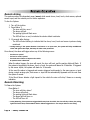
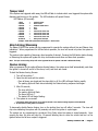
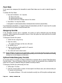
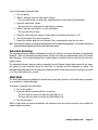
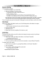
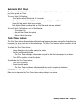
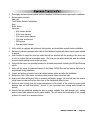
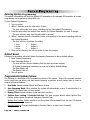
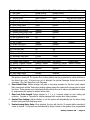
5100RS-2
2W
SERIES
VEHICLE SECURITY SYSTEM
WITH REMOTE START
PRODUCT MANUAL
Limited Lifetime Warranty
This vehicle security system is warranted to the original purchaser, to be free from defects in
material and workmanship. The manufacturer will repair or replace at its option, and free of
charge for the first twelve (12) months, any part that proves defective in material or workmanship
under normal installation, use, and service, provided the product is returned to the manufacturer
freight prepaid. After the first 12 month warranty period there will be a maximum service charge
of $25.00 per calendar year (if required) for repair and/or replacement of any defective parts.
A copy of the original purchase receipt must accompany any products returned for warranty
service. Warranty is limited to defective parts and/or replacement parts only and excludes any
incidental, and consequential damages connected therewith.
The manufacturer of this theft deterrent system makes no warranty against the theft of the vehicle
or its contents. This warranty is not to be construed as an insurance policy against loss.
WARRANTY OF INSTALLATION LABOR, REMOVAL AND RE-INSTALLATION CHARGES ARE
NOT THE RESPONSIBILITY OF THE MANUFACTURER.
Table of Contents
1.
2.
3.
4.
5.
6.
7.
8.
9.
10.
11.
12.
13.
14.
15.
About Your System . . . . . . . . . . . . . . . . . . . . . . . . . . . . . . . . . . . . . . . . . . . . . . . . . . . . . . .Page 1
Remote Transmitters . . . . . . . . . . . . . . . . . . . . . . . . . . . . . . . . . . . . . . . . . . . . . . . . . . . . . .Page 2
Remote Transmitter Description . . . . . . . . . . . . . . . . . . . . . . . . . . . . . . . . . . . . . . . . . .Page 2
Adding/Replacing Transmitters . . . . . . . . . . . . . . . . . . . . . . . . . . . . . . . . . . . . . . . . . .Page 2
Two Car Operation . . . . . . . . . . . . . . . . . . . . . . . . . . . . . . . . . . . . . . . . . . . . . . . . . . .Page 3
Battery Replacement . . . . . . . . . . . . . . . . . . . . . . . . . . . . . . . . . . . . . . . . . . . . . . . . .Page 3
Optional 2-way LCD Remote Transmitter Description . . . . . . . . . . . . . . . . . . . . . . . . . . .Page 4
Adding/Replacing Optional 2-way Transmitters, Selecting Vibrating Mode. . . . . . . . . .Page 4&6
LCD Transmitter Battery Replacement . . . . . . . . . . . . . . . . . . . . . . . . . . . . . . . . . . . . .Page 5
System Operation . . . . . . . . . . . . . . . . . . . . . . . . . . . . . . . . . . . . . . . . . . . . . . . . . . . . . . . .Page 8
Remote Arming . . . . . . . . . . . . . . . . . . . . . . . . . . . . . . . . . . . . . . . . . . . . . . . . . . . . .Page 8
Remote Disarming . . . . . . . . . . . . . . . . . . . . . . . . . . . . . . . . . . . . . . . . . . . . . . . . . . .Page 8
Tamper Alert . . . . . . . . . . . . . . . . . . . . . . . . . . . . . . . . . . . . . . . . . . . . . . . . . . . . . . .Page 9
Silent Arming/Disarming . . . . . . . . . . . . . . . . . . . . . . . . . . . . . . . . . . . . . . . . . . . . . . .Page 9
Passive Arming . . . . . . . . . . . . . . . . . . . . . . . . . . . . . . . . . . . . . . . . . . . . . . . . . . . . .Page 9
Panic Mode . . . . . . . . . . . . . . . . . . . . . . . . . . . . . . . . . . . . . . . . . . . . . . . . . . . . . . .Page 10
Emergency Override . . . . . . . . . . . . . . . . . . . . . . . . . . . . . . . . . . . . . . . . . . . . . . . . .Page 10
Optional Coded Emergency Override . . . . . . . . . . . . . . . . . . . . . . . . . . . . . . . . . . . . .Page 10
Automatic Rearming . . . . . . . . . . . . . . . . . . . . . . . . . . . . . . . . . . . . . . . . . . . . . . . . .Page 11
Valet Mode . . . . . . . . . . . . . . . . . . . . . . . . . . . . . . . . . . . . . . . . . . . . . . . . . . . . . . .Page 11
Remote Start Features . . . . . . . . . . . . . . . . . . . . . . . . . . . . . . . . . . . . . . . . . . . . . . . . . . . .Page 12
Remote Starting . . . . . . . . . . . . . . . . . . . . . . . . . . . . . . . . . . . . . . . . . . . . . . . . . . . .Page 12
Shut Down . . . . . . . . . . . . . . . . . . . . . . . . . . . . . . . . . . . . . . . . . . . . . . . . . . . . . . .Page 12
Quick Stop . . . . . . . . . . . . . . . . . . . . . . . . . . . . . . . . . . . . . . . . . . . . . . . . . . . . . . . .Page 12
Automatic Start Mode . . . . . . . . . . . . . . . . . . . . . . . . . . . . . . . . . . . . . . . . . . . . . . . .Page 13
Turbo Timer Feature . . . . . . . . . . . . . . . . . . . . . . . . . . . . . . . . . . . . . . . . . . . . . . . . .Page 13
Extended Features . . . . . . . . . . . . . . . . . . . . . . . . . . . . . . . . . . . . . . . . . . . . . . . . . . . . . . .Page 14
Ignition Door Locking . . . . . . . . . . . . . . . . . . . . . . . . . . . . . . . . . . . . . . . . . . . . . . . .Page 14
Ignition Door Unlocking . . . . . . . . . . . . . . . . . . . . . . . . . . . . . . . . . . . . . . . . . . . . . .Page 14
Dome Light Activation . . . . . . . . . . . . . . . . . . . . . . . . . . . . . . . . . . . . . . . . . . . . . . . .Page 14
Auxiliary Function Outputs . . . . . . . . . . . . . . . . . . . . . . . . . . . . . . . . . . . . . . . . . . . .Page 14
Disarm with Auxiliary Function . . . . . . . . . . . . . . . . . . . . . . . . . . . . . . . . . . . . . . . . . .Page 14
Remote Sensor Disable . . . . . . . . . . . . . . . . . . . . . . . . . . . . . . . . . . . . . . . . . . . . . . .Page 14
System Installation . . . . . . . . . . . . . . . . . . . . . . . . . . . . . . . . . . . . . . . . . . . . . . . . . . . . . .Page 15
Mounting the Control unit . . . . . . . . . . . . . . . . . . . . . . . . . . . . . . . . . . . . . . . . . . . . .Page 16
Mounting the Siren . . . . . . . . . . . . . . . . . . . . . . . . . . . . . . . . . . . . . . . . . . . . . . . . . .Page 16
Mounting the Shock Sensor . . . . . . . . . . . . . . . . . . . . . . . . . . . . . . . . . . . . . . . . . . . .Page 16
System Wiring . . . . . . . . . . . . . . . . . . . . . . . . . . . . . . . . . . . . . . . . . . . . . . . . . . . . . . . . .Page 17
6-Pin Starter Harness . . . . . . . . . . . . . . . . . . . . . . . . . . . . . . . . . . . . . . . . . . . . . . . .Page 17
20-Pin Main Harness . . . . . . . . . . . . . . . . . . . . . . . . . . . . . . . . . . . . . . . . . . . . . . . . .Page 17
Plug-in Connectors . . . . . . . . . . . . . . . . . . . . . . . . . . . . . . . . . . . . . . . . . . . . . . . . . .Page 18
Jumper Settings . . . . . . . . . . . . . . . . . . . . . . . . . . . . . . . . . . . . . . . . . . . . . . . . . . . . . . . .Page 19
Jumper Selection . . . . . . . . . . . . . . . . . . . . . . . . . . . . . . . . . . . . . . . . . . . . . . . . . . .Page 19
System Programming . . . . . . . . . . . . . . . . . . . . . . . . . . . . . . . . . . . . . . . . . . . . . . . . . . . . .Page 20
Entering System Programming . . . . . . . . . . . . . . . . . . . . . . . . . . . . . . . . . . . . . . . . . .Page 20
Default Reset . . . . . . . . . . . . . . . . . . . . . . . . . . . . . . . . . . . . . . . . . . . . . . . . . . . . . .Page 20
Programmable System Options . . . . . . . . . . . . . . . . . . . . . . . . . . . . . . . . . . . . . . . . .Page 20
Branch Table . . . . . . . . . . . . . . . . . . . . . . . . . . . . . . . . . . . . . . . . . . . . . . . . . . . . . .Page 21
Wiring Diagrams . . . . . . . . . . . . . . . . . . . . . . . . . . . . . . . . . . . . . . . . . . . . . . . . . . . . . . . .Page 24
Door Lock Diagrams . . . . . . . . . . . . . . . . . . . . . . . . . . . . . . . . . . . . . . . . . . . . . . . . . . . . .Page 25
Two Stage Door Lock Diagrams . . . . . . . . . . . . . . . . . . . . . . . . . . . . . . . . . . . . . . . . . . . . .Page 26
Technical Information . . . . . . . . . . . . . . . . . . . . . . . . . . . . . . . . . . . . . . . . . . . . . . . . . . . .Page 28
System Diagnostics . . . . . . . . . . . . . . . . . . . . . . . . . . . . . . . . . . . . . . . . . . . . . . . . . . . . . .Page 29
Wiring Diagram . . . . . . . . . . . . . . . . . . . . . . . . . . . . . . . . . . . . . . . . . . . . . . . . . . . . . . .Back Page
About Your System
The ScyTek Galaxy 5100RS Plus is a combination vehicle security and remote starting system featuring a
built-in "ScyNet Network Port" that allows direct connection of optional accessory modules and a PC
interface offering expanded system operation. With proper installation this system will provide superior
protection and performance for many years to come.
The Galaxy 5100RS Plus’ built-in remote start feature is designed to offer maximum convenience by remote
starting your vehicle’s engine, turning on the heater/air conditioner, and then running for a pre-determined
time to provide a comfortable environment once you enter your vehicle.
To ensure the safety and security of the system while it is remote started, the Galaxy 5100RS Plus employs
several safeguards. In the event the alarm is triggered while the engine is remotely running, the remote
start will immediately shutdown to prevent unauthorized users from attempting to drive the vehicle. The
system is equipped with a hood pin input to prevent access to the engine compartment while the vehicle
is remotely running. The Valet Mode prevents the remote start feature from operating in the event the
vehicle is to be serviced. Finally, the brake pedal also acts as a safety by shutting down the remote start
when pressed.
System Contents:
•
•
•
•
•
•
•
Main Unit with built-in ScyNet Network Interface Port
5-Button 2-Way LCD Remote Transmitter
5-Button Random Code Remote Transmitter
High Output 6-tone Siren
Dual Stage Shock Sensor
Status LED
Coded Emergency Override / Valet Switch
Optional ScyNet Network Interface Accessories:
•
•
ScyNet Network Interface Software
Two-Way FM Paging Module w/ LCD Transmitter
Options and Convenience Features*
This ScyTek system includes several optional inputs and outputs allowing the creation of a completely
·
·
·
·
·
·
·
Second Car Operation
Keyless Entry
Two Stage Door Unlocking
Starter Defeat
Horn Honk
Illuminated Entry
Turbo Timer
·
·
·
·
·
·
Remote Window Control
Power Trunk / Hatch Release
Glass Breakage Sensor
Radar Sensor
Remote Head Lamp Control
Back-up Battery Siren
personalized security and convenience system by offering many optional features such as:
*May require additional parts and/or labor, see store for details.
Some of the features described in this manual may require additional parts and/or labor, and may not be included
as part of the standard installation of this unit. Additionally, many features of this security system have
selectable options that must be activated or programmed during the system’s installation. These items will be
identified in the following sections. Please discuss these features and any questions you may have regarding the
installation of this product with Your Authorized Dealer.
Galaxy 5100RS-2W - Page 1
Remote Transmitters
Standard Remote Transmitter Description
LED
Button 2
Button 1
Button 4
Button 3
Button 5
The Galaxy 5100RS Plus is compatible with the optional 5-button Remote Transmitters used to control
system operations.
Note: Using the optional PC or Pocket PC interface with the network software, it is possible to reconfigure
the functionality of the transmitter buttons. The standard (default) setting for operation of the transmitters
is described below.
Button 1 Arms the system and when held for 2 seconds, activates the system’s Panic feature. Button 1 also
locks the doors when the system is in Valet Mode.
Button 2 Disarms the system. Pressing Button 2 again operates the Passenger Unlock feature (if installed).
Button 2 also unlocks the doors when the system is in Valet Mode.
Button 3 Activates the Auxiliary 1 output. This output will remain on for as long as the button is pressed.
Button 4 Activates the Remote Start feature.
Button 5 is the Page Shift button. Each time the Shift Button is pressed, the LED on the transmitter will
illuminate and the transmitter functions will shift to the next page, allowing access to another set of
features. Once shifted to another page (there are 4 pages total), the transmitter will remain on that page
for 10 seconds or until a button is pressed, then return to page 1. Each time a transmitter button is pressed
and held, the LED will flash a number of times to indicate from which page it is transmitting. Under
normally operation, only pages 1 and 2 are used. Pages 3 and 4 are usually used for Two Car Operation
(see page 3) or optional expansion modules.
Shift then Button 1 Arms the system silently.
Shift then Button 2 Disarms the system silently.
Shift then Button 3 Activates the Auxiliary 2 output. This output will remain on for as long as the button
is pressed.
Page 2 - Galaxy 5100RS-2W
Adding/Replacing Transmitters
To replace lost or stolen transmitters or to add additional transmitters into the system, have all desired
transmitters ready and follow the steps below.
Note: Up to 4 transmitters can be programmed to operate the system. To erase any previously stored
transmitter codes, be sure to program all 4 transmitter memory locations.
To program the transmitter(s):
1. Turn on the ignition key On, Off, On, Off, and back On. (Key On 3 times)
· The siren will chirp 3 times.
2. Press and hold the Override switch for 5 seconds.
· The siren will chirp 5 times.
· The LED will illuminate.
3. Press Button 1 on the first transmitter.
· The siren will chirp once.
4. Press Button 1 on the first transmitter again.
· The siren will chirp twice to indicate it has learned the code.
5. Repeat steps 3 and 4 for each transmitter (up to 4).
6. Turn off the ignition key.
Two Car Operation
If two vehicles are equipped with Galaxy 5000RS Plus systems, for convenience both can be operated using
the same remote transmitter. If all four transmitters are to be used with both cars, program transmitters
A and B into the first vehicle in the manner described above. Program transmitters C and D by pressing
the Shift button twice before performing steps 3 and 4 above.
When finished programming the first vehicle, program transmitters C and D into the second vehicle as
normal, then program transmitters A and B by pressing the Shift button twice before performing steps 3
and 4 above.
When programmed in this manner, the driver of the first car can also operate the second vehicle by pressing
the Shift button twice and the desired function button.
Battery Replacement
Your Remote Transmitter uses two 3 volt lithium batteries (type CR2016), which will require
replacement in time. Depending on the amount of use, the batteries may last up to six months
or more before they need replacement.
In order to change the battery, first remove the screw from the back of the transmitter and separate the
top and bottom halves of the case.
While replacing the battery make sure that the positive and negative terminals are positioned correctly, then
carefully reassemble the transmitter case.
Galaxy 5100RS-2W - Page 3
True Color 2-way LCD Remote Transmitter Description
Button 1
Button 2
Button 3
Button 4
The Galaxy 5100RS-TC is compatible with the True Color 2-way LCD remote transmitter,
offering increased range and confirmation of any activated features.
Button 1 Arms the system. Button 1 also locks the doors when the system is in Valet Mode.
Button 2 Disarms the system. Button 2 also unlocks the doors when the system is in Valet
Mode.
Button 3 When Pressed and released momentarily activates the Auxiliary Output 2. When
pressed for 2 seconds Acitvates the Remote Start feature.
Button 1 and 2 When pressed together for 2 seconds Activates the Panic Feature
Button 3 and 4 When pressed together for 2 seconds Activates the Auxiliary 1 output normally
used for trunk release.
Button 4 is the Confirmation button. Quickly pressing button 4 will activate the LCD display’s
backlighting for use in the dark. Pressing button 4 for 2 seconds activates the system’s
confirmation feature which will then display the current status of the system (armed,
disarmed, engine running, etc.).
Adding/Replacing Optional True Color 2-way LCD Transmitters
When adding an optional 2-way LCD transmitter to the system, follow these steps:
1. Turn on the ignition key On, Off, On, Off, On, Off, and back On. (Key On 4 times)
· The siren will chirp 4 times.
2. Press and hold the Override switch for 5 seconds.
· The siren will chirp 4 times.
· The LED will illuminate.
3. Press Button 1 on the first transmitter.
· The siren will chirp once.
Page 4 - Galaxy 5100RS-2W
4. Turn off the ignition key.
5. Repeat steps 1-4 to add an additional 2-way transmitter.
LCD Transmitter Battery Replacement
Your Galaxy Remote Transmitter uses a 1.5 volt AAA alkaline battery, which will require
replacement in time. Depending on the amount of use, the battery may last up to six months
before it needs replacement. When the battery needs replacing, the system’s operating range
will decrease, the LCD display will show only one of three bars in the battery icon, or the
display and sounds may suddenly stop and start as the battery voltage drops below minimum.
In order to change the battery, first slide the battery door locking pin to the side. Carefully
slide the battery cover downward until it is free. While replacing the battery make sure that
the positive and negative terminals are positioned correctly, then carefully reassemble the
transmitter case.
Galaxy 5100RS-2W - Page 5
LCD Backlight
Transmitter Button 4 is used for confirmation, transmitter programming, as well as activation of
the LCD backlighting for use in the dark. Press button 4 momentarily to activate the LCD
backlight.
System Confirmation
The 2-way transmitter's confirmation feature allows the current vehicle status to be displayed
at any time.
To display system status:
Press and hold Button 4 until the display shows CON.
· The transmitter will beep once.
Page 6 - Galaxy 5100RS-2W
Galaxy 5100RS-2W - Page 7
System Operation
Remote Arming
The system monitors 6 independent areas (zones) while armed: doors, hood, trunk, shock sensor, optional
sensor input, and the network port for future expansion.
To Arm the System:
1. Turn off the ignition.
2. Press Button 1.
· The siren will chirp once.*
· The doors will lock.
· The parking lights will flash once.
· The LED will turn on red, to indicate the starter defeat is activate.
3. 10 seconds after Arming:
· The LED will start blinking to indicate that the doors, hood, trunk and sensor inputs are being
monitored.
* During Arming, if the system detects a bad sensor or an open zone, the system will chirp 4 additional
times and ignore that input, but keep all other areas protected.
Once Armed, the alarm will trigger when any of the following occurs:
· The doors are opened.
· The hood or trunk is opened.
· The shock sensor detects an impact to the vehicle.
· An optional sensor is disturbed.
When the alarm triggers, the siren will sound, the horn will honk, and the parking lights will flash. If
the system is triggered by the doors, hood, or trunk, the system will alarm for 45 seconds. If triggered
by the sensor inputs, the system will alarm for 30 seconds.
In the event the alarm is triggered and remains triggered continuously by the same sensor or input
during a single arming cycle, that sensor or input will be automatically bypassed until the next time
the system is armed.
If the Shock Sensor detects a light impact to the vehicle the siren will chirp 5 times as a warning
indication.
Remote Disarming
To Disarm the System:
Press Button 1.
· The siren will chirp twice.*
· The doors will unlock.
· The parking lights will flash twice.
· The dome light will turn on.
· The LED will turn off.
* During Disarming, if the system was triggered while away from the vehicle, the siren will chirp 3 times, the parking
lights will flash 3 times, and the LED will flash to indicate triggered zone. See Tamper Alert for zone listing.
Page 8 - Galaxy 5100RS-2W
Tamper Alert
If the system was triggered while away, the LED will flash to indicate which zone triggered the system after
disarming and turning on the ignition. The LED indication will repeat 8 times.
LED Flashes (60 seconds):
1 flash
2 flashes
3 flashes
4 flashes
5 flashes
6 flashes
7 flashes
8 flashes
9 flashes
10 flashes
=
=
=
=
=
=
=
=
=
=
optional sensor
shock sensor
network based sensor
door
trunk
reserved for future use
reserved for future use
reserved for future use
reserved for future use
main power interrupt
example: flash-flash-pause-flash-flash-pause = shock sensor
Silent Arming/Disarming
The Galaxy 5100RS Plus system can be programmed to operate the system without Arm and Disarm chirp
indications. When programmed for full-time silent operation, the siren will sound only when the system is
triggered.
The system is also capable of temporary silent operation if desired. Pressing the Shift button before Arming
or Disarming the system will bypass the chirp confirmations and allow one-time silent operation.
Note: The open zone warning chirps will not be bypassed when the system is Armed or Disarmed silently.
Passive Arming
When programmed for the optional Passive Arming feature, the system arms itself automatically, each time
the ignition is turned off and all of the doors, hood, and trunk are closed.
To start the Passive Arming Process:
1. Turn off the ignition.*
2. Open the door and exit the vehicle.
· Once all doors are closed and the dome light is off, the LED will begin flashing rapidly.
· The parking lights will flash twice indicating the Passive Arming sequence has begun.
3. After 30 seconds,
· The siren will chirp.
· The parking lights will flash.
· The doors will lock.**
· The status LED will begin flashing.
4. The system is now armed.
* The ignition must have been on for at least 5 seconds or the Passive Arming sequence will be disabled.
** If the Passive Locking feature is selected.
To temporarily disable Passive Arming, turn on the ignition then turn off within 5 seconds. The siren will
chip once indicating the system will not passively arm until the ignition is cycled again.
The system can be programmed to provide an Entry Delay when the system is armed passively. Upon
opening the door the siren will chirp for 10 seconds allowing time to enter the vehicle and turn on the
ignition before the full siren output is triggered.
Galaxy 5100RS-2W - Page 9
Panic Mode
In the event of an emergency the transmitter’s remote Panic feature can be used to instantly trigger the
alarm.
To activate the Panic Mode:
1. Press and hold Button 1 for 3 seconds.
· The alarm will sound.
· The parking lights will flash.
· The doors will unlock* allowing access to the vehicle.
2. Press Button 2 to stop Panic Mode.
* If the ignition is on when the Panic feature is activated, the doors will lock for personal safety.
If not deactivated using Button 2, the Panic Mode will automatically exit after 30 seconds and the system
will be restored to its previous Armed/Disarmed state.
Emergency Override
If the transmitter becomes lost or inoperable, the system can still be disarmed using the following
procedure. Before beginning this procedure be sure to have the ignition key ready and know the location
of the override switch.
To Emergency Override the system:
1. Unlock the door using the key.
2. Enter the vehicle.
· The system will trigger and the siren will sound.
3. Turn ignition key on.
4. Press and hold the override switch for 10 seconds.
· The system will disarm.
5. The vehicle will now be able to start.
Note: During installation, the system can be programmed to provide a 15 second entry delay when the system Arms
passively. If a door is opened after the system is Armed passively, the siren will chirp for 10 seconds before sounding,
allowing time to use the emergency override feature.
Optional Coded Emergency Override
As an extra measure of security, the Galaxy 5100RS Plus is equipped with an optional Coded Emergency
Override feature. Once an Emergency Override Code is chosen and programmed during installation, the
system can no longer be disarmed using the standard override procedure.
To Emergency Override the system using the Code:
1. Follow steps 1-3 above.
2. Press the override switch a number of times equal to the Disarm code, and continue holding for
10 seconds on the last press.
· The system will disarm. If the code is entered incorrectly, turn off the ignition and begin again.
Page 10 - Galaxy 5100RS-2W
To set the Emergency Override Code:
1. Turn on ignition.
2. Within 5 seconds, press the valet switch 5 times.
· The siren will provide one long chirp, indicating that you have entered Programming.
3. Press the valet switch 4 times.
· The siren will chirp each time the valet switch is pressed.
4. Within 5 seconds, press Button 3 on the transmitter.
· The siren will chirp 3 times.
5. Press the valet switch the number of time equal to the desired code (from 1-15).
6. Turn off the ignition then arm the system.
7. Disarm the system using the new Override Code to permanently store the new code.
Note: If the code set procedure is not properly performed, turn off the ignition and begin again. The override code will not
be permanently stored until the code is used to disarm the system.
Automatic Rearming
The automatic Rearming feature is designed to protect the vehicle in the event the system is accidentally
disarmed. With the Automatic Rearming feature enabled, the alarm will automatically rearm 30 seconds
after disarming. If the optional Passive Door Locking feature is enabled, the doors will also lock when the
system rearms.
The Automatic Rearming feature functions separately from the Passive Arming feature and will only rearm
the system if it was previously armed for more than 10 seconds and then disarmed by remote. The
Automatic Rearming feature will be temporarily bypassed until the next arming cycle if the ignition is turned
on or the trunk/hood zone is opened.
Valet Mode
The Valet Mode temporarily disables the security and remote start system so the vehicle may be operated
by a mechanic or parking attendant.
To activate or deactivate the Valet Mode:
1. Turn on the ignition.
2. Press and hold the override switch for 5 seconds.
· The siren will chirp once to confirm the Valet Mode is on.
· The siren will chirp twice to confirm the Valet Mode is off.
3. Turn off the ignition.
While in Valet Mode the remote transmitters will continue to lock and unlock the doors, and operate the
optional auxiliary functions.
Galaxy 5100RS-2W - Page 11
Remote Start Features
Remote Starting
To Remote Start the System:
1. Be sure the system is not in Valet Mode.
2. Press and hold Button 4 for three seconds.
· The parking lights will flash 4 times and turn on.
· The Siren will chirp 4 times.
· The engine will start and run for the duration of its programmed Run Time.*
· The heater or air conditioner will turn on (if turned on prior to exiting the vehicle).
*If the engine fails to start on the first attempt, it will repeat the starting procedure 2 more times. If the vehicle
fails to start after a total of 3 times the parking lights will flash 4 times and the doors will lock (if installed).
Turn on the ignition and press the bake pedal to disengage the remote start feature and drive the vehicle.
Shut Down
When the the Remote Start feature is active, any of the following actions will shutdown the engine:
1. Pressing Button 4.
· After the engine shuts down the doors will lock (if installed).
2. Pressing the Brake Pedal.
3. Opening the Hood.
4. Remote Start Time-Out (completion of the timed run cycle).
Quick Stop
The Quick Stop Feature allows you exit the vehicle while keeping the engine running for quick stops.
To leave the vehicle running:
2. While engine running push Remote Start button on the Remote Transmitter.
· The parking lights will turn On.
4. Remove the key from the ignition switch.
5. You may now exit the vehicle and lock the doors manually or using the Remote Transmitter
To resume control of the vehicle:
1. Unlock the doors manually or by pressing Disarm Button on the Remote Transmitter*.
2. Turn on the ignition.
3. Press the Brake Pedal to disengaged the remote start.
· The parking lights will turn Off.
*If optional keyless entry feature is installed.
Page 12 - Galaxy 5100RS-2W
Automatic Start Mode
The Automatic Start Mode allows the vehicle to automatically start the vehicle every one or two hours and
run for the preset Run Time.
To turn on Auto Cold Starting:
1. Turn Ignition switch Off and wait for 3 seconds.
2. Turn Ignition switch On and Off three times ending with Ignition in Off position
3. Press the Valet switch within three seconds
Side lights will flash indicating that the Cold Start mode has been activated.
To turn off Auto Cold Starting do one of the following:
· Turn ignition On.
· Arm and then Disarm the system
· Alarm or Panic the system
Turbo Timer Feature
The Turbo Timer feature allows vehicles with turbocharged engines to remain running after the ignition key
is removed, for proper cool-down of the turbocharger. The Turbo Timer feature requires connection to the
vehicle’s parking brake wire.
To activate the Turbo Timer feature:
1. Leave the engine running after parking the vehicle.
2. Set the vehicle’s parking brake.
· The Turbo Timer will begin a two-minute run cycle to allow the turbocharger to cool down.
3. Turn OFF the ignition and exit the vehicle.
To deactivate the Turbo Timer feature:
1. Turn OFF the ignition.
2. Press the brake pedal.
· The Turbo Timer countdown will automatically stop and the engine will shutdown.
WARNING: the Turbo Timer feature is not intended for use inside garages or other non-ventilated areas.
Make sure to deactivate the Turbo Timer feature when parking in such areas.
Galaxy 5100RS-2W - Page 13
Extended Features
Ignition Door Locking
For added safety, the Ignition Door Locking feature allows vehicles equipped with power door lock systems
to automatically lock the doors when the ignition is turned on. If a door is open when the ignition is turned
on, the Ignition Door Locking feature is disabled to protect against locking the keys inside the vehicle.
Ignition Door Unlocking
For added convenience, this feature automatically unlocks the doors after the ignition key is turned off. If
the optional Passenger Unlock feature is installed, the Ignition Door Unlocking feature can be programmed
to unlock only the driver door as a higher measure of safety, especially when children are present. The
Ignition Door Unlocking feature may also be completely disabled if desired.
Dome Light Activation
If the optional Dome Light Activation feature is installed, the dome light will turn on when the system is
disarmed using the Remote Transmitter, and remain on for 30 seconds or until the ignition is turned on.
Auxiliary Function Outputs
The Galaxy 5100RS Plus system is equipped with 3 Auxiliary Channel Outputs allowing the convenience
features of the system to be further expanded. These outputs can be programmed for pulsed, timed, or
latched operation, and used to add a number of optional features such as: power trunk release, remote
engine start, power window activation, power sunroof control, auxiliary lighting, audio/video system control,
and more.
The Pulsed operation setting allows an output to activate as long as the button is held.
The Timed operation setting allows an output to activate when the transmitter button is pressed, and
remain activated for 10 seconds or until the transmitter button is pressed again.
Note: With the optional ScyNet network interface and Wizard software, the timed output can be programmed for any time
between 1 second and 255 seconds.
The Latched operation setting allows an output to activate when the transmitter button is pressed, and
remain activated until the transmitter button is pressed again.
Disarm with Auxiliary Function
If Auxiliary 1 is installed to activate the vehicle’s trunk release, the system can be programmed to
automatically disarm the alarm when the trunk is opened using the transmitter. In this manner, the trunk
can be accessed without first disarming the alarm.
Remote Sensor Disable
When parking the vehicle in areas susceptible to unwanted disturbance from animals or strong weather
conditions that could cause the sensors to trigger, the sensor inputs can be temporarily bypassed using the
Remote Transmitter, preventing possible false alarms.
To disable the sensor inputs :
1. Arm the system normally.
2. Within 5 seconds of Arming the system, press the Arm button again.
· The siren will chirp 5 times and the parking lights will flash 5 times to indicate the sensors are disabled.
· The sensors will remain disabled until the next arming cycle.
Page 14 - Galaxy 5100RS-2W
System Installation
1.
2.
Thoroughly read and become familiar with the installation instructions before beginning the installation.
Review system contents:
Main Unit
Two 5-Button Remote Transmitters
Siren
Shock Sensor
Harnesses
•
•
•
•
•
•
6-Pin starter harness
20-Pin main harness
4-Pin shock sensor harness
3-Pin door lock harness
LED harness
Override Switch harness
3.
4.
Verify vehicle is equipped with electronic fuel injection, and starts/idles normally before installation.
Determine if vehicle is equipped with a factory theft deterrent system and obtain proper bypass module
if required.
5. Find a location to mount the hood pin switch that will not interfere with the opening of the hood, and
is not in a position that can accumulate water. The hood pin is a safety device that must be installed
to avoid remote starting during engine servicing.
6. Verify with the owner, the mounting locations for all visible components, including the LED and Override
switch.
7. Verify with the owner, the optional features of the Galaxy 5100RS Plus and the features that must be
programmed during installation.
8. Inspect and perform a function test of all vehicle systems before and after the installation.
9. Always use a Volt / Ohm meter for testing vehicle circuits. Never use a test light.
10. Always look before drilling any holes or mounting self-tapping screws. Be sure fuel lines and exterior
wiring looms are clear as they are often close to the chassis and difficult to see.
11. Protect all wires running from the engine compartment to the interior of the vehicle by covering with
electrical tape and split loom tubing. Be sure to use a grommet when routing wires through the
firewall.
12. Properly fuse any additional accessories such as window modules, door lock actuators, etc., making
sure to power them separate from the alarm module. This will ensure the functionality of the security
system in the event of an accessory failure.
Galaxy 5100RS-2W - Page 15
Mounting the Control Unit
The control unit must only be mounted in the interior of the vehicle. Do not mount the main unit in
the engine compartment. Choose a mounting location that will not be easily accessible to a thief, and
will not interfere with the operation of any vehicle components such as foot pedals, steering column,
air vents, seat rails, etc.
Do not mount the control unit until after setting the internal jumpers and performing a complete
operation check of the system. After installation is complete and performance verified, the control unit
can be easily mounted using wire ties through the mounting tabs on the bottom of the unit.
Mounting the Siren
Choose a siren mounting location that is away from heat sources such as exhaust manifolds, and
where it cannot be easily accessed from underneath the vehicle. Be sure to face the siren downward
to prevent the collection of water in the siren’s housing.
Always route all wires from the engine compartment into the interior of the vehicle through a proper
grommet.
Mounting the Shock Sensor
Choose a suitable interior mounting location for the shock sensor that provides ample coverage of the
vehicle. Keep the sensor away from the vehicle’s ECM or other sources of electrical interference.
Suggested mounting locations include air conditioning ducts, dashboard braces, or center console
supports.
During proper operation, the shock sensor will detect impacts to the vehicle only and will not usually
be triggered by slow rocking movements of the vehicle like those caused by wind.
Page 16 - Galaxy 5100RS-2W
System Wiring
6-Pin Starter Harness
Pin 1 RED WIRE A: Main Power Input A (+). Connect to the battery or constant power wire at the ignition
switch with a minimum 25 Amp supply. Remove the fuse until the installation is complete and all wiring
is checked.
Pin 2 RED WIRE B: Main Power Input B (+). Connect to the battery or constant power wire at the ignition
switch with a minimum 25 Amp supply. Note: if connecting at the ignition switch it is highly
recommended to use separate power wires for each Red wire, each with a minimum 30A supply.
Remove the fuse until the installation is completed and all wiring is checked.
Pin 3 BROWN WIRE: Second Ignition Output (+). The Brown wire provides +12V for a second ignition
wire. This wire may instead be programmed for use as a second accessory or second starter wire.
Pin 4 ORANGE WIRE: Accessory Output (+). Connect to the accessory wire coming from the ignition
switch that supplies power to the heater/air-conditioner. Some cars may have multiple accessory wires.
Pin 5 YELLOW WIRE: Ignition Output (+). Connect to the main ignition wire that provides +12V when the
ignition is on and while cranking the starter.
Pin 6 VIOLET WIRE: Starter Output (+). Connect to the the vehicle’s starter wire.
20-Pin Main Harness
Pin 1 GREEN/WHITE WIRE: Brake Input (+). Connect to the wire that shows +12V when pressing the
brake. The Green/white wire is a safety shutdown wire that must be connected.
Pin 2 BLACK/GRAY WIRE: Tach Input. Connect to the vehicle’s tach wire or a fuel injector wire if the
tachless mode does not provide satisfactory operation.
Pin 3 WHITE/RED WIRE: Auxiliary 2 Output (-) 500 mA. Connect to a relay or module for an optional
feature such as power window activation, etc. This output may be programmed for momentary, timed,
or latched operation.
Pin 4 BLACK/WHITE WIRE: Dome Light Output (-) 500 mA. Connect to the wire that activates the
vehicle’s dome light, usually the door pin switch wire. NOTE: The dome light output can usually connect
to the same wire used for the door trigger input (see Green and Violet door trigger wires).
Pin 5 YELLOW WIRE: +12V Ignition Input. The Yellow wire must connect to a main ignition wire at the
ignition harness. This wire must show +12V when the ignition is on and while cranking the starter. The
voltage must not drop when the car is starting.
Pin 6 BLUE/YELLOW WIRE: Glow Plug Input (+). For vehicles equipped with diesel engines the
Blue/yellow wire must be connected to the wait-to-start light in the gauge panel. This wire will show
+12V when the light is on, and ground when the light turns off. If the wait-to-start wire shows ground
when the light is on, a relay must be installed (see wiring diagrams).
Pin 7 BLUE/WHITE WIRE: Passenger Unlock Output (-) 500 mA. Connect to a relay to unlock the
passenger doors when the system is configured for Driver Priority Unlocking.
Pin 8 BLUE/ORANGE WIRE: Ground When Running Output (-) 500 mA. Connect to an optional factory
security bypass module if required.
Pin 9 BLACK WIRE: Ground Input (-). The Black wire must connect to a solid chassis ground. Clean away
any paint or dirt to insure the best possible ground.
Pin 10 RED WIRE: Module Power Input (+). Connect to a constant source of +12V.
Pin 11 VIOLET WIRE: Positive Door Input (+). Connect to the door switch circuit wire that shows +12V
Galaxy 5100RS-2W - Page 17
Pin 12
Pin 13
Pin 14
Pin 15
Pin 16
Pin 17
Pin 18
Pin 19
Pin 20
when the door is open. This type of door circuit is usually found on Ford vehicles.
GREEN WIRE: Negative Door Input (-). Connect to the door switch circuit wire that shows ground
when the door is open.
WHITE/BLACK WIRE: Hood Pin Input (-). Connect the to the hood pin switch. The switch must
provide a ground output when switch is opened.
ORANGE WIRE: Armed Output (-) 500 mA. The Orange wire provides a ground output while armed
to activate a relay for starter defeat and anti-grind protection.
VIOLET/WHITE WIRE: Factory Disarm Output (-) 500 mA. The Violet/white wire provides a ground
output on disarming and before remote starting to disarm a factory security system. Connect to the
wire that requires a ground pulse to disarm the factory security system.
WHITE/VIOLET WIRE: Factory Rearm Output (-) 500 mA. The White/violet wire provides a ground
output on remote start shutdown to rearm a factory security system. Connect to the wire that requires
a ground pulse to rearm the factory security system.
BROWN WIRE: Siren Output (+) 3A. The Brown wire must connect to the siren’s red wire. The Black
siren wire must be grounded.
GRAY WIRE: Auxiliary 1 Output (-) 500 mA. Connect to a relay for an optional feature such as trunk
release, etc. This output may be programmed for momentary, timed, or latched operation.
WHITE WIRE: Parking Light Output (+/-) relay. Connect the White wire to the circuit that shows
+12V or ground only when the parking lights are on and set the internal parking light relay jumper to
the proper polarity. For parking light circuits exceeding 10 amps, a relay is required. For vehicle’s with
independent left and right parking light circuits, diodes must be installed to keep the circuits separate.
NOTE: Do not connect the WHITE wire to the vehicle’s headlight circuit.
BROWN/WHITE WIRE: Horn Output (-) 500 mA. Connect to a relay to activate the vehicle’s horn
when the alarm is triggered. This wire may instead be programmed as an ignition 3 relay trigger.
Plug-in Connectors
4-Pin White Connector: Dual stage shock sensor port.
2-Pin Blue Connector: Valet switch port. Mount program switch in an area that is easily accessible from
the driver’s position.
2-Pin Red Connector: LED port. Mount LED in an area where it may be easily seen from either side of
the vehicle.
3-Pin White Door Lock Connector: Door lock port.
· BLUE WIRE - negative unlock output (-) 500mA.
· RED WIRE - (+) 500mA trigger output for optional plug-in door lock relay module,
· GREEN WIRE - negative lock output (-) 500mA.
3-Pin Blue Connector: The plug-in network connector port is located on the side of the main module.
This network port may be used with the optional personal computer interface or Pocket PC for diagnostics,
software customization and expanded programming options. The network also offers connection to several
optional accessories. See your dealer for more information.
2-Pin White Connector: Located on the side of the main module.
· Green WIRE - Parking Brake Input (-) For vehicles equipped with a turbo charged engine. Must be
connected if using the Turbo Timer feature.
· Blue WIRE - Not Used.
Page 18 - Galaxy 5100RS-2W
Jumper Settings
Jumper Selection
Carefully separate the top and bottom halves of the main unit case. Once the cover is removed, the parking
light polarity jumper will be visible next to the parking light relay. Set the jumper for the correct polarity
output as described below, then reassembly the main unit case.
Parking Light Output. Selects the polarity (+/-) for the output of the on-board Parking Light relay.
Left Pin + Center Pin = positive
Right Pin + Center Pin = negative
default setting shown
Galaxy 5100RS-2W - Page 19
System Programming
Entering System Programming
This system is compatible with both the optional LCD transmitter or the standard AM transmitter, all system
programming can be performed using either one.
To enter System Programming:
1. Turn on ignition.
2. Within 5 seconds, press the valet switch 5 times.
· The siren will provide three chirps, indicating that you have entered Programming.
3. Press the valet switch the number times equal to the System Parameter you want to change.
· The siren will chirp each time the valet switch is pressed.
4. Within 5 seconds, press the transmitter button corresponding to the desired operating mode for
that System Parameter.
· The siren will chirp to indicate the setting.
1 chirp
=
Button 1
2 chirps
=
Button 2
3 chirps
=
Button 3
5. When you are finished, turn off the ignition to save the changes.
Default Reset
Following this procedure will set all System Programming Parameters to factory default settings.
1. Enter System Programming.
2. Press Transmitter Button 3.
· The siren will chirp 6 times indicating that the reset signal was received.
· All System Programming parameters are now set to factory default settings.
· The Valet Mode is off.
· The Disarm Code is 1.
3. Turn off ignition.
Programmable System Options
The following is a description of the programming options of the system. Some of the program branches
control more than one option, and may require accessing a particular branch number twice in order to
program all desired features.
1. Arm Mode. Selects between Manual and Passive Arming.
2. Auto Rearming Mode. When selected, the system will automatically re-arm 30 seconds after it is
disarmed if the doors have not been opened.
3. Arming Chirps. Selects between normal and silent operation.
4. Ignition Door Locking / Override Code Set. This dual program branch selects Ignition Door
Locking, and programs the optional Emergency Override Code.
Ignition Door Locking. Selects whether or not the system will automatically lock the doors 10 seconds
after the ignition key is turned on.
Override Code Set. Changes the Emergency Override Code for a higher level of security.
Page 20 - Galaxy 5100RS-2W
Branch Feature
Button 1 (default) Button 2
Button 3
1. Arm Mode
Manual Arming
Passive Arming
2. Auto Rearming Mode
Disabled
Enabled
3. Arming Chirps
Siren Chirps En
Silent
Siren & Horn Chirps En.
4. Ignition Door Locking
On
Off
Set Override Code
5. Ignition Door Unlocking
Unlock All
Unlock Driver Only Off
6. Door Unlock Pulse
Single
Double
7. Door Lock Pulse Length
1 second
3 seconds
0.1 seconds
8. Passive Door Locking
Disabled
Enabled
9. Passive Arming Entry Delay
Disabled
Enabled
10. Ignore Open Door Report
Off
Ignore
11. Aux 2 Activate on Arm
Off
On
12. Aux 1 Mode
Pulsed
Timed
Latched
13. Aux 2 Mode
Pulsed
Timed
Latched
14. Disarm with Aux 1
Disabled
Enabled
15. Start in Valet Mode
Disabled
Enabled
16. Lock after Start
On
Off
17. Lock after Shutdown
On
Off
18. Engine Run Time
15 minutes
25 minutes
19. Automatic Start Mode
2 hours
1 hour
20. Engine Sense Mode
Tachless
21. Remote Start Program
RPM Learn/Tach Monitor Gas Engine
Diesel Engine
22. Ignition 2 Output Program
Ignition 2 Output
Accessory 2 Output Starter 2 Output
23. Horn Honk Output
Horn Output
Ignition 3 Output
24. Turbo Timer
Disabled
Enabled
25. Extended Parking Lights
On
Off
26. Warn-Away Report
Enabled
Disabled
5. Ignition Door Unlocking. Selects whether or not the system automatically unlocks the doors when
the ignition is turned off. The Ignition Door Locking feature may be programmed to unlock all doors or
the driver’s door only. If driver’s door only is selected, the optional Passenger Unlock wire must be
connected. (See Two Stage Door Lock Diagrams)
6. Door Unlock Pulse. Selects between one pulse or two pulse operation for the door unlock output.
Many new import vehicles’ factory door locking systems require two pulses on the proper wire to unlock
the doors. These systems can be interfaced directly without the use of relays or any additional circuitry
by programming the system for double unlock pulse.
7. Door Lock Pulse Length. Selects between a 1, 3 or 0.1 seconds output for door locking and
unlocking. Program to 3 seconds for vehicles equipped with vacuum door locking systems.
8. Passive Door Locking. Selects whether or not the system will automatically lock the doors during
Passive Arming and Auto Rearming mode.
9. Passive Arming Entry Delay. When selected, the siren will chirp for 10 seconds before sounding if
a door is opened. The system may be disarmed by simply turning on the ignition when programmed
Galaxy 5100RS-2W - Page 21
10.
11.
12.
13.
14.
15.
16.
17.
18.
19.
20.
21.
for this feature.
Ignore Open Door Report. Bypasses the open zone warning chirps for vehicles equipped with a
residual dome light circuit that remains on for a period of time after closing the door.
Aux 2 Auto Activate with Arm. When selected, the Auxiliary 2 output will activate when the system
is armed. This feature can be used to roll-up windows, close sunroofs, activate accessories, etc.
Auxiliary 1 Mode. Selects from momentary, 10 second timed, or latched operation for Auxiliary 1.
Momentary operation provides an output for as long as the transmitter button is pressed.
Timed operation provides an output that turns on for 10 seconds each time the transmitter button is
pressed. If the button is pressed again during the 30 seconds, the output will turn off.
Latched operation provides an output that turns on when the transmitter button is pressed and remains
on until the transmitter button is pressed again.
Note: With the optional ScyNet network interface and Wizard software, any auxiliary function can be
programmed to output for 1 second up to 255 seconds.
Auxiliary 2 Mode. Selects from Momentary, Timed, or Latched operation for Auxiliary 2.
Disarm with Auxiliary 1. When selected, activating the Auxiliary 1 output (usually used to open the
trunk) will disarm the alarm.
Start in Valet Mode. Selects whether or not the vehicle can remote start while in the valet mode.
Lock After Start. When selected, the doors will automatically lock after remote starting.
Lock After Shutdown. When selected, the doors will automatically lock after remote shutdown.
Engine Run Time. Selects between 15 or 25 minutes for the remote start run cycle.
Automatic Start Mode. Selects between every two hours or every hour for the automatic engine
starting feature.
Engine Sense Mode. Selects between Tachless and Tach Monitor operation.
Tachless. Determines the engine status using an advanced software routine, without requiring
connection to the vehicle’s tachometer. Tachless operation may not be compatible with some vehicles
or in severe temperatures, in which case the tach wire must be connected.
RPM Learn/Tach Monitor This dual program branch sets the engine mode for Gas or Diesel, and
learns the vehicle’s RPM threshold. For installation into a diesel equipped vehicle, first set the engine
type to diesel before learning RPM.
RPM Learn/Tach Monitor. start the engine, enter Branch 21 and press Button 1 to learn the vehicle’s
tach signal and set to Tach Monitor Mode. The siren will chirp and the LED will flash once to confirm
learning of the tach signal and set to Tach Monitor Mode. The siren will chirp four times and the LED
will flash four times if the tach signal was not learned.
Tach Monitor mode: monitors the vehicle’s tach wire (or a fuel injection wire) in real-time to determine
engine status and adjust starter crank time automatically.
Gas Engine. Sets the engine type for Gasoline.
Diesel Engine. Sets the engine type for Diesel and monitors the glow plug input to make sure the glow
plugs are warm before cranking the starter. If the glow plug wire is not connected, the built-in timer
waits 15 seconds before automatically cranking the starter.
Page 22 - Galaxy 5100RS-2W
22. Ignition 2 Relay Program. Selects one of three operating modes for the Ignition 2 relay output:
Ignition 2, Accessory 2, or Starter 2.
23. Horn Output. When set for Horn Output the horn wire will pulse when the alarm is triggered. When
Ignition 3 Output is selected, the output will activate during remote start to trigger a relay for Ignition 3.
24. Turbo Timer. When enabled, if the emergency brake has been applied Ignition power will be kept On
for a predetermined time (2min. Factory Default) from the application of the emergency brake.
25. Extended Parking Lights. When Enabled, upon Disarming Parking lights will turn On for 30 seconds
or untill the Dome light turns Off.
26. Warn-Away Pager Report. When Enabled, Warn-Away report will be sent to the pager. If Disabled
no Warn-Away report will be sent to the pager.
Galaxy 5100RS-2W - Page 23
Wiring Diagrams
Positive Dome Light
Negative Dome Light
Positive Horn Honk
Negative Horn Honk
Negative Glow Plug
Starter Defeat/Anti-Grind
Page 24 - Galaxy 5100RS-2W
Door Lock Diagrams
Follow the diagrams below for connecting basic door lock systems. For Two Stage door lock
systems (separately unlocks driver and passenger doors) see following pages.
Negative Trigger
Positive Trigger
Green Wire
Blue Wire
Reverse Polarity
Vacuum
Adding Actuators
Galaxy 5100RS-2W - Page 25
Two Stage Door Lock Diagrams
The Galaxy 5100RS Plus is equipped with a dedicated Passenger Unlock output allowing Two
Stage Door Lock operation. When connected as shown below, disarming the system will unlock
only the driver’s door. Pressing the disarm button again will unlock all doors.
Two Stage Negative Trigger
Two Stage Positive Trigger
Green Wire
Blue Wire
Page 26 - Galaxy 5100RS-2W
Two Stage Door Lock Diagrams cont’d
Two Stage Reverse Polarity
Two Stage Adding Actuators
Galaxy 5100RS-2W - Page 27
Technical Information
FCC ID: OARRXAM2000
This device complies with Part 15 of FCC Rules.
Operation is subject to the following two conditions:
1) This device may not cause harmful interference.
2) This device must accept any interference received, including interference that may cause
undesired operation
Page 28 - Galaxy 5100RS-2W
Starter Diagnostics
Starter doesn’t start and Side Lights flash:
3 Times Engine RPM not detected
Hood Trigger is active
4 Times - Brake Trigger is active
5 Times - Unit is in Valet (service) mode, and start is disabled.
Galaxy 5100RS-2W - Page 29
Page 30 - Galaxy 5100RS-2W
Notes
Galaxy 5100RS-2W - Page 31
Galaxy 5100RS-2W
ScyNet
Port
Emergency brake(-)
Start (-)
Green
Blue
Antenna
Wiring Diagram
Green Lock output (-) 500mA
Red
+12V relay power output 100mA
Blue Unlock output (-) 500mA
Shock Sensor
LED
Valet Switch
Green/White
Black/Gray
White/Red
Black/White
Yellow
Blue/Yellow
Blue/White
Blue/Orange
Black
Red
Violet
Green
White/Black
Orange
Violet/White
White/Violet
Brown
Gray
White
Brown/White
Brake Input(+)
Tachometer Input
Auxiliary 2 Output (-)500mA
Dome Light output (-)500mA
Ignition Input (+)
Glow plug (wait to start) Input (+)
Passenger Unlock Output (-)500mA
Remote Start Output (-)500mA
Ground
+12V Battery Input #3
Door Trigger Input (+)
Door Trigger Input (-)
Hood/Trunk Input (-)
Armed Output (-)500mA
Factory ALarm Disarm Output (-)500mA
Factory Alarm Arm Output (-)500mA
Siren Output (+)3A
Auxiliary 1 Output (-)500mA
Parking Light Output (+/- built-in relay)
Horn Output (-)500mA
Violet
Starter Output
Yellow
Ignition 1 Output
Orange
Accessory Output
Brown
Ignition 2 Output
Red
+12V Battery Input #1
Red
+12V Battery Input #2
ScyTek Electronics
11627 Cantara Street Unit B
North Hollywood, CA 91605
© ScyTek Electronics 2004
Galaxy 5100RS-2W r4 10/21