1
Hart Scientific
1529
Chub-E4 Thermometer Readout
User’s Guide
Rev. 692801
Limited Warranty & Limitation of Liability
Each product from Fluke Corporation, Hart Scientific Division ("Hart") is warranted to be free from defects in material and workmanship under normal use and service. The warranty period is 2 years for the
Thermometer Readout. The warranty period begins on the date of the shipment. Parts, product repairs,
and services are warranted for 90 days. The warranty extends only to the original buyer or end-user customer of a Hart authorized reseller, and does not apply to fuses, disposable batteries or to any other product, which in Hart's opinion, has been misused, altered, neglected, or damaged by accident or abnormal
conditions of operation or handling. Hart warrants that software will operate substantially in accordance
with its functional specifications for 90 days and that it has been properly recorded on non-defective media. Hart does not warrant that software will be error free or operate without interruption. Hart does not
warrant calibrations on the Thermometer Readout.
Hart authorized resellers shall extend this warranty on new and unused products to end-user customers
only but have no authority to extend a greater or different warranty on behalf of Hart. Warranty support is
available if product is purchased through a Hart authorized sales outlet or Buyer has paid the applicable
international price. Hart reserves the right to invoice Buyer for importation costs of repairs/replacement
parts when product purchased in one country is submitted for repair in another country.
Hart's warranty obligation is limited, at Hart's option, to refund of the purchase price, free of charge repair, or replacement of a defective product which is returned to a Hart authorized service center within
the warranty period.
To obtain warranty service, contact your nearest Hart authorized service center or send the product, with
a description of the difficulty, postage, and insurance prepaid (FOB Destination), to the nearest Hart authorized service center. Hart assumes no risk for damage in transit. Following warranty repair, the product will be returned to Buyer, transportation prepaid (FOB Destination). If Hart determines that the
failure was caused by misuse, alteration, accident or abnormal condition or operation or handling, Hart
will provide an estimate or repair costs and obtain authorization before commencing the work. Following
repair, the product will be returned to the Buyer transportation prepaid and the Buyer will be billed for
the repair and return transportation charges (FOB Shipping Point).
THIS WARRANTY IS BUYER'S SOLE AND EXCLUSIVE REMEDY AND IS IN LIEU OF ALL
OTHER WARRANTIES, EXPRESS OR IMPLIED, INCLUDING BUT NOT LIMITED TO ANY IMPLIED WARRANTY OF MERCHANTABILITY OR FITNESS FOR A PARTICULAR PURPOSE.
HART SHALL NOT BE LIABLE FOR ANY SPECIAL, INDIRECT, INCIDENTAL. OR CONSEQUENTIAL DAMAGES OR LOSSES, INCLUDING LOSS OF DATA, WHETHER ARISING FROM
BREACH OF WARRANTY OR BASED ON CONTRACT, TORT, RELIANCE OR ANY OTHER
THEORY.
Since some countries or states do not allow limitation of the term of an implied warranty, or exclusion or
limitation of incidental or consequential damages, the limitations and exclusions of this warranty may not
apply to every buyer. If any provision of this Warranty is held invalid or unenforceable by a court of competent jurisdiction, such holding will not affect the validity or enforceability of any other provision.
Fluke Corporation, Hart Scientific Division
799 E. Utah Valley Drive • American Fork, UT 84003-9775 • USA
Phone: +1.801.763.1600 • Telefax: +1.801.763.1010
E-mail: [email protected]
www.hartscientific.com
Subject to change without notice. • Copyright © 2005 • Printed in USA
Rev. 692801
Table of Contents
1 Before You Start . . . . . . . . . . . . . . . . . . . . . . . . . . 1
1.1
1.2
Symbols Used . . . . . . . . . . . . . . . . . . . . . . . . . . . . 1
Safety Information . . . . . . . . . . . . . . . . . . . . . . . . . . 2
1.2.1
1.2.2
1.3
Warnings . . . . . . . . . . . . . . . . . . . . . . . . . . . . . . . . . . . . . 2
Cautions . . . . . . . . . . . . . . . . . . . . . . . . . . . . . . . . . . . . . 3
Authorized Service Centers. . . . . . . . . . . . . . . . . . . . . . 4
2 Introduction . . . . . . . . . . . . . . . . . . . . . . . . . . . . 7
3 Specifications and Environmental Conditions . . . . . . . . . . 9
3.1
3.2
Specifications . . . . . . . . . . . . . . . . . . . . . . . . . . . . . 9
Environmental Conditions. . . . . . . . . . . . . . . . . . . . . . 10
4 Quick Start . . . . . . . . . . . . . . . . . . . . . . . . . . . . 11
4.1
4.2
Unpacking . . . . . . . . . . . . . . . . . . . . . . . . . . . . . . 11
Use Proper Care . . . . . . . . . . . . . . . . . . . . . . . . . . . 11
4.3
4.4
Learn About the Features and Components . . . . . . . . . . . . . 11
Connect the Probe . . . . . . . . . . . . . . . . . . . . . . . . . . 11
4.4.1
4.5
4.6
4.7
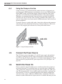
Using the Clamp-on Ferrites . . . . . . . . . . . . . . . . . . . . . . . . . . 12
Connect the Power Source . . . . . . . . . . . . . . . . . . . . . 12
Switch the Power On . . . . . . . . . . . . . . . . . . . . . . . . 12
Measure Temperature . . . . . . . . . . . . . . . . . . . . . . . . 13
5 Parts and Controls . . . . . . . . . . . . . . . . . . . . . . . . 15
5.1
Front Panel Buttons . . . . . . . . . . . . . . . . . . . . . . . . . 15
5.2
5.3
Back Panel. . . . . . . . . . . . . . . . . . . . . . . . . . . . . . 17
Accessories . . . . . . . . . . . . . . . . . . . . . . . . . . . . . 17
6 General Operation . . . . . . . . . . . . . . . . . . . . . . . . 19
6.1
6.2
6.3
6.4
Display . . . . . . .
Changing Units . . .
Battery . . . . . . . .
Probe Input Modules
6.4.1
6.4.2
6.5
.
.
.
.
.
.
.
.
.
.
.
.
.
.
.
.
.
.
.
.
.
.
.
.
.
.
.
.
.
.
.
.
.
.
.
.
.
.
.
.
.
.
.
.
.
.
.
.
.
.
.
.
.
.
.
.
.
.
.
.
.
.
.
.
.
.
.
.
.
.
.
.
.
.
.
.
.
.
.
.
.
.
.
.
.
.
.
.
.
.
.
.
.
.
.
.
19
19
19
20
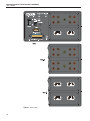
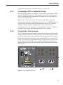
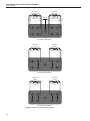
Connecting a PRT or Thermistor Probe . . . . . . . . . . . . . . . . . . . . 21
Connecting a Thermocouple . . . . . . . . . . . . . . . . . . . . . . . . . . 21
DC Power Source . . . . . . . . . . . . . . . . . . . . . . . . . . 23
i
6.6
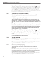
Power On Self-Test . . . . . . . . . . . . . . . . . . . . . . . . . 23
6.7
6.8
Display Backlight and Contrast . . . . . . . . . . . . . . . . . . . 23
Taking Measurements . . . . . . . . . . . . . . . . . . . . . . . . 23
6.8.1
6.8.2
6.8.3
6.9
6.10
Connecting the Sensor . . . . . . . . . . . . . . . . . . . . . . . . . . . . . 23
Enabling the Channel . . . . . . . . . . . . . . . . . . . . . . . . . . . . . . 24
Selecting Conversion Type and Probe Characterization . . . . . . . . . . . . 24
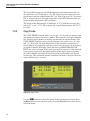
Fast Measurement Mode . . . . . . . . . . . . . . . . . . . . . . 24
Data Logging . . . . . . . . . . . . . . . . . . . . . . . . . . . . 25
7 Menu Functions. . . . . . . . . . . . . . . . . . . . . . . . . . 27
7.1
Channel Menu . . . . . . . . . . . . . . . . . . . . . . . . . . . . 27
7.1.1
7.1.2
7.1.3
7.1.4
7.1.5
7.2
Measure Period and Fast Measurement Mode
Enable Channel . . . . . . . . . . . . . . . .
Channel Mode. . . . . . . . . . . . . . . . .
Moving Average. . . . . . . . . . . . . . . .
Display Options/Auto-Cal . . . . . . . . . .
7.2.2
7.2.3
7.2.4
7.2.5
.
.
.
.
.
.
.
.
.
.
.
.
.
.
.
.
.
.
.
.
.
.
.
.
.
.
.
.
.
.
.
.
.
.
.
.
.
.
.
.
.
.
.
.
.
.
.
.
.
.
.
.
.
.
.
.
.
.
.
.
.
.
.
.
.
.
.
.
.
.
28
30
31
31
32
ITS-90 Conversion . . . . . . . . . . . . .
ITS-SR5 . . . . . . . . . . . . . . . . . . .
PT-100 Conversion . . . . . . . . . . . . .
Callendar-Van Dusen (CVD) conversion . .
RES Conversion. . . . . . . . . . . . . . .
Thermistor T(R) Conversion [THERM-T] .
Thermistor R(T) Conversion [THERM-R] .
YSI-400 Conversion . . . . . . . . . . . .
Thermocouple Volts [Vin[mV]] . . . . . .
Standard Thermocouple Conversions. . . .
Thermocouple Polynomial Conversion . . .
Copy Probe .
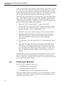
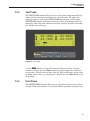
Test Probe . .
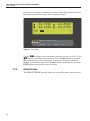
Print Probe .
Default Probe
.
.
.
.
.
.
.
.
.
.
.
.
.
.
.
.
.
.
.
.
.
.
.
.
.
.
.
.
.
.
.
.
.
.
.
.
.
.
.
.
.
.
.
.
.
.
.
.
.
.
.
.
.
.
.
.
.
.
.
.
.
.
.
.
.
.
.
.
.
.
.
.
.
.
.
.
.
.
.
.
.
.
.
.
.
.
.
.
.
.
.
.
.
.
.
.
.
.
.
.
.
.
.
.
.
.
.
.
.
.
.
.
.
.
.
.
.
.
.
.
.
.
.
.
.
.
.
.
.
.
.
.
.
.
.
.
.
.
.
.
.
.
.
.
.
.
.
.
.
.
.
.
.
.
.
.
.
.
.
.
.
.
.
.
.
.
.
.
.
.
.
.
.
.
.
.
.
.
.
.
.
.
.
.
.
.
.
.
.
.
.
.
.
.
.
.
.
.
.
.
.
.
.
.
.
.
.
.
.
.
.
.
.
.
.
.
.
.
.
.
.
.
.
.
.
.
.
.
.
.
.
.
.
.
.
.
.
.
.
.
.
.
.
.
.
.
.
.
.
.
.
.
.
.
.
.
.
.
.
.
.
.
.
.
.
.
.
.
.
.
.
.
.
.
.
.
.
.
.
.
.
.
.
.
.
.
.
.
.
.
.
.
.
.
.
.
.
.
.
.
.
.
.
.
.
.
.
.
.
.
.
.
.
.
.
.
.
.
.
.
.
.
.
.
.
.
.
.
.
.
.
.
.
.
.
.
.
.
.
.
.
.
.
.
.
.
.
.
.
.
.
.
.
.
.
.
.
.
.
. 36
. 37
. 38
. 38
. 39
. 39
. 40
. 40
. 40
. 41
. 41
.
.
.
.
. 42
. 43
. 43
. 44
Fields Menu . . . . . . . . . . . . . . . . . . . . . . . . . . . . . 45
7.3.1
7.3.2
7.3.3
7.3.4
7.3.5
Clear Stats . . . .
Select Fields. . .
Edit Fields . . . .
Default Fields . .
Display Options .
.
.
.
.
.
.
.
.
.
.
.
.
.
.
.
.
.
.
.
.
.
.
.
.
.
.
.
.
.
.
.
.
.
.
.
.
.
.
.
.
.
.
.
.
.
.
.
.
.
.
.
.
.
.
.
.
.
.
.
.
.
.
.
.
.
.
.
.
.
.
.
.
.
.
.
.
.
.
.
.
.
.
.
.
.
.
.
.
.
.
.
.
.
.
.
.
.
.
.
.
.
.
.
.
.
.
.
.
.
.
.
.
.
.
.
.
.
.
.
.
.
.
.
.
.
.
.
.
.
.
.
.
.
.
.
.
.
.
.
.
.
.
.
.
.
.
.
.
.
.
.
.
.
.
.
. 46
. 47
. 49
. 49
. 50
Logging Menu. . . . . . . . . . . . . . . . . . . . . . . . . . . . 51
7.4.1
Demand Log . . . . . . . . . . . . . . . . . . . . . . . . . . . . . . . . . . 52
7.4.1.1
7.4.1.2
7.4.1.3
7.4.1.4
7.4.1.5
7.4.2
Store Reading .
Log History . .
View Data . . .
Print Data . . .
Delete Data . .
.
.
.
.
.
.
.
.
.
.
.
.
.
.
.
.
.
.
.
.
.
.
.
.
.
.
.
.
.
.
.
.
.
.
.
.
.
.
.
.
.
.
.
.
.
.
.
.
.
.
.
.
.
.
.
.
.
.
.
.
.
.
.
.
.
.
.
.
.
.
.
.
.
.
.
.
.
.
.
.
.
.
.
.
.
.
.
.
.
.
.
.
.
.
.
.
.
.
.
.
.
.
.
.
.
.
.
.
.
.
.
.
.
.
.
.
.
.
.
.
.
.
.
.
.
.
.
.
.
.
.
.
.
.
.
.
.
.
.
.
.
.
.
.
.
.
.
.
.
.
.
.
.
.
.
.
.
.
.
.
.
.
.
.
.
.
.
.
.
.
.
.
.
.
.
.
.
.
.
.
. 53
. 54
. 55
. 56
. 57
Auto Log . . . . . . . . . . . . . . . . . . . . . . . . . . . . . . . . . . . . 58
7.4.2.1
7.4.2.2
7.4.2.3
7.4.2.4
ii
.
.
.
.
.
Edit Probe . . . . . . . . . . . . . . . . . . . . . . . . . . . . . . . . . . . . 34
7.2.1.1
7.2.1.2
7.2.1.3
7.2.1.4
7.2.1.5
7.2.1.6
7.2.1.7
7.2.1.8
7.2.1.9
7.2.1.10
7.2.1.11
7.4
.
.
.
.
.
Probe Menu . . . . . . . . . . . . . . . . . . . . . . . . . . . . . 33
7.2.1
7.3
.
.
.
.
.
Logging Options
Start Stop . . . .
View Data . . . .
Print Data . . . .
.
.
.
.
.
.
.
.
.
.
.
.
.
.
.
.
.
.
.
.
.
.
.
.
.
.
.
.
.
.
.
.
.
.
.
.
.
.
.
.
.
.
.
.
.
.
.
.
.
.
.
.
.
.
.
.
.
.
.
.
.
.
.
.
.
.
.
.
.
.
.
.
.
.
.
.
.
.
.
.
.
.
.
.
.
.
.
.
.
.
.
.
.
.
.
.
.
.
.
.
.
.
.
.
.
.
.
.
.
.
.
.
.
.
.
.
.
.
.
.
.
.
.
.
.
.
.
.
.
.
.
.
.
.
.
.
.
.
.
.
. 59
. 60
. 62
. 63
7.4.2.5
7.4.3
7.4.4
7.4.5
7.5
Delete Data . . . . . . . . . . . . . . . . . . . . . . . . . . . . . . . . . . . . . . . 63
Log Stats . . . . . . . . . . . . . . . . . . . . . . . . . . . . . . . . . . . . 64
Data Labels . . . . . . . . . . . . . . . . . . . . . . . . . . . . . . . . . . . 65
Default Labels. . . . . . . . . . . . . . . . . . . . . . . . . . . . . . . . . . 66
System Menu . . . . . . . . . . . . . . . . . . . . . . . . . . . . 67
7.5.1
Comm Setup . . . . . . . . . . . . . . . . . . . . . . . . . . . . . . . . . . 68
7.5.1.1
7.5.1.2
7.5.2
7.5.3
7.5.4
7.5.5
Serial . . . . . . . . . . . . . . . . . . . . . . . . . . . . . . . . . . . . . . . . . . 69
GPIB (Optional) . . . . . . . . . . . . . . . . . . . . . . . . . . . . . . . . . . . . 70
Date Time . .
Password . .
Calibration .
System Reset
.
.
.
.
.
.
.
.
.
.
.
.
.
.
.
.
.
.
.
.
.
.
.
.
.
.
.
.
.
.
.
.
.
.
.
.
.
.
.
.
.
.
.
.
.
.
.
.
.
.
.
.
.
.
.
.
.
.
.
.
.
.
.
.
.
.
.
.
.
.
.
.
.
.
.
.
.
.
.
.
.
.
.
.
.
.
.
.
.
.
.
.
.
.
.
.
.
.
.
.
.
.
.
.
.
.
.
.
.
.
.
.
.
.
.
.
.
.
.
.
.
.
.
.
.
.
.
.
.
.
.
.
. 70
. 71
. 73
. 75
8 Digital Communications Interface . . . . . . . . . . . . . . . 77
8.1
8.2
Overview . . . . . . . . . . . . . . . . . . . . . . . . . . . . . . 77
Communications . . . . . . . . . . . . . . . . . . . . . . . . . . 77
8.2.1
8.2.2
Serial Wiring . . . . . . . . . . . . . . . . . . . . . . . . . . . . . . . . . . 77
GPIB Communications . . . . . . . . . . . . . . . . . . . . . . . . . . . . . 78
8.2.2.1
8.2.2.2
8.2.2.3
8.3
Interface Commands . . . . . . . . . . . . . . . . . . . . . . . . 78
8.3.1
8.3.2
8.4
Capability . . . . . . . . . . . . . . . . . . . . . . . . . . . . . . . . . . . . . . . . 78
Connection . . . . . . . . . . . . . . . . . . . . . . . . . . . . . . . . . . . . . . . 78
Device Setup . . . . . . . . . . . . . . . . . . . . . . . . . . . . . . . . . . . . . . 78
Command Summary . . . . . . . . . . . . . . . . . . . . . . . . . . . . . . 78
Command Syntax . . . . . . . . . . . . . . . . . . . . . . . . . . . . . . . . 83
Commands . . . . . . . . . . . . . . . . . . . . . . . . . . . . . 84
8.4.1
Measurement Commands . . . . . . . . . . . . . . . . . . . . . . . . . . . . 86
8.4.1.1
8.4.1.2
8.4.1.3
8.4.1.4
8.4.1.5
8.4.1.6
8.4.1.7
8.4.1.8
8.4.1.9
8.4.2
.
.
.
.
.
.
.
.
.
.
.
.
.
.
.
.
.
.
.
.
.
.
.
.
.
.
.
.
.
.
.
.
.
.
.
.
.
.
.
.
.
.
.
.
.
.
.
.
.
.
.
.
.
.
.
.
.
.
.
.
.
.
.
.
.
.
.
.
.
.
.
.
.
.
.
.
.
.
.
.
.
.
.
.
.
.
.
.
.
.
.
.
.
.
.
.
.
.
.
.
.
.
.
.
.
.
.
.
.
.
.
.
.
.
.
.
.
.
.
.
.
.
.
.
.
.
.
.
.
.
.
.
.
.
.
.
.
.
.
.
.
.
.
.
.
.
.
.
.
.
.
.
.
.
.
.
.
.
.
.
.
.
.
.
.
.
.
.
.
.
.
.
.
.
.
.
.
.
.
.
.
.
.
.
.
.
.
.
.
.
.
.
.
.
.
.
.
.
. 86
. 86
. 86
. 87
. 88
. 88
. 88
. 88
. 88
Measurement Control Commands . . . . . . . . . . . . . . . . . . . . . . . 88
8.4.2.1
8.4.2.2
8.4.2.3
8.4.2.4
8.4.2.5
8.4.2.6
8.4.2.7
8.4.2.8
8.4.2.9
8.4.2.10
8.4.3
CALCulate:AVERage:CLEar. . . . . . .
CALCulate<chn>:AVERage<n>:DATA?.
CALCulate:AVERage<n>:TYPE? . . . .
FETCh? [<chn>] . . . . . . . . . . . . .
FORMat:STAMp? . . . . . . . . . . . .
FORMat:STAMp <bool> . . . . . . . . .
MEASure? [<chn>] . . . . . . . . . . . .
READ? [<chn>]. . . . . . . . . . . . . .
SENSe<chn>:DATA? . . . . . . . . . . .
INITiate . . . . . . . . . . . . . . . . . . . . . . . . . . . .
INITiate:CONTinuous? . . . . . . . . . . . . . . . . . . . .
SENSe:AVERage:COUNt? [MIN|MAX|DEF] . . . . . . . .
SENSe:AVERage:COUNt <num>|MIN|MAX|DEF . . . . .
SENSe<chn>:RESistance:RANGe? [MIN|MAX|DEF] . . .
SENSe<chn>:RESistance:RANGe <num>|MIN|MAX|DEF
SENSe<chn>:RESistance:WIRE? [MIN|MAX|DEF] . . . .
SENSe<chn>:RESistance:WIRE <num>|MIN|MAX|DEF .
TRIGger:TIMer? [MIN|MAX|DEF] . . . . . . . . . . . . .
TRIGger:TIMer <num>|MIN|MAX|DEF . . . . . . . . . .
.
.
.
.
.
.
.
.
.
.
.
.
.
.
.
.
.
.
.
.
.
.
.
.
.
.
.
.
.
.
.
.
.
.
.
.
.
.
.
.
.
.
.
.
.
.
.
.
.
.
.
.
.
.
.
.
.
.
.
.
.
.
.
.
.
.
.
.
.
.
.
.
.
.
.
.
.
.
.
.
.
.
.
.
.
.
.
.
.
.
.
.
.
.
.
.
.
.
.
.
.
.
.
.
.
.
.
.
.
.
.
.
.
.
.
.
.
.
.
.
. 89
. 89
. 89
. 89
. 89
. 90
. 90
. 90
. 91
. 91
Channel Commands. . . . . . . . . . . . . . . . . . . . . . . . . . . . . . . 91
8.4.3.1
8.4.3.2
8.4.3.3
8.4.3.4
8.4.3.5
8.4.3.6
8.4.3.7
8.4.3.8
ROUTe:CLOSe? <chn>. . . . . . . . . . . . . .
ROUTe:CLOSe <chn> . . . . . . . . . . . . . .
ROUTe:OPEN? <chn> . . . . . . . . . . . . . .
ROUTe:OPEN <chn> . . . . . . . . . . . . . . .
ROUTe:SCAN? . . . . . . . . . . . . . . . . . .
ROUTe:SCAN <chn list>. . . . . . . . . . . . .
ROUTe:SCAN:MODE? [MIN|MAX|DEF] . . .
ROUTe:SCAN:MODE <num>|MIN|MAX|DEF .
.
.
.
.
.
.
.
.
.
.
.
.
.
.
.
.
.
.
.
.
.
.
.
.
.
.
.
.
.
.
.
.
.
.
.
.
.
.
.
.
.
.
.
.
.
.
.
.
.
.
.
.
.
.
.
.
.
.
.
.
.
.
.
.
.
.
.
.
.
.
.
.
.
.
.
.
.
.
.
.
.
.
.
.
.
.
.
.
.
.
.
.
.
.
.
.
.
.
.
.
.
.
.
.
.
.
.
.
.
.
.
.
.
.
.
.
.
.
.
.
.
.
.
.
.
.
.
.
.
.
.
.
.
.
.
.
.
.
.
.
.
.
.
.
iii
. 91
. 92
. 92
. 92
. 92
. 92
. 92
. 93
8.4.4
Probe Commands . . . . . . . . . . . . . . . . . . . . . . . . . . . . . . . . 93
8.4.4.1
8.4.4.2
8.4.4.3
8.4.4.4
8.4.4.5
8.4.4.6
8.4.4.7
8.4.4.8
8.4.4.9
8.4.4.10
8.4.4.11
8.4.5
Calibration Coefficient Commands . . . . . . . . . . . . . . . . . . . . . . . 97
8.4.5.1
8.4.5.2
8.4.5.3
8.4.5.4
8.4.5.5
8.4.5.6
8.4.5.7
8.4.5.8
8.4.5.9
8.4.5.10
8.4.5.11
8.4.5.12
8.4.5.13
8.4.6
.
.
.
.
.
.
.
.
.
.
.
.
.
.
.
.
.
.
.
.
.
.
.
.
.
.
.
.
.
.
.
.
.
.
.
.
.
.
.
.
.
.
.
.
.
.
.
.
.
.
.
.
.
.
.
.
.
.
.
.
.
.
.
.
.
.
.
.
.
.
.
.
.
.
.
.
.
.
.
.
.
.
.
.
.
.
.
.
.
.
.
.
.
.
.
.
.
.
.
.
.
.
.
.
.
.
.
.
.
.
.
.
.
.
.
.
.
.
.
.
.
.
.
.
.
.
.
.
.
.
101
101
102
102
102
102
103
103
103
103
LOGging:AUTomatic:DELete [<num>|ALL] . . . . . .
LOGging:AUTomatic:COUNt? [MIN|MAX|DEF] . . . .
LOGging:AUTomatic:COUNt <num>|MIN|MAX|DEF .
LOGging:AUTomatic:FREE? . . . . . . . . . . . . . . .
LOGging:AUTomatic:LABel? [MIN|MAX|DEF] . . . .
LOGging:AUTomatic:LABel <num>|MIN|MAX|DEF . .
LOGging:AUTomatic:POINt? [MAX] . . . . . . . . . .
LOGging:AUTomatic:PRINt [<num>|ALL [,<port>]] . .
LOGging:AUTomatic:STATus? . . . . . . . . . . . . . .
LOGging:AUTomatic:STATus <bool> . . . . . . . . . .
LOGging:AUTomatic:TIMe? [MIN|MAX|DEF] . . . . .
LOGging:AUTomatic:TIMe <num>|MIN|MAX|DEF . .
LOGging:AUTomatic:VALue? <num>|MIN|MAX|DEF .
LOGging:DEMand:DELete [<num>|ALL] . . . . . . . .
LOGging:DEMand:FREE? . . . . . . . . . . . . . . . .
LOGging:DEMand:LABel? [MIN|MAX|DEF] . . . . . .
LOGging:DEMand:LABel <num>|MIN|MAX|DEF . . .
LOGging:DEMand:POINt? . . . . . . . . . . . . . . . .
LOGging:DEMand:PRINt [<num>|ALL [,<port>]] . . .
LOGging:DEMand:STORe . . . . . . . . . . . . . . . .
LOGging:DEMand:VALue? <num>|MIN|MAX|DEF . .
LOGging:LABel<n>:NAME?. . . . . . . . . . . . . . .
LOGging:LABel<n>:NAME <label> . . . . . . . . . . .
.
.
.
.
.
.
.
.
.
.
.
.
.
.
.
.
.
.
.
.
.
.
.
.
.
.
.
.
.
.
.
.
.
.
.
.
.
.
.
.
.
.
.
.
.
.
.
.
.
.
.
.
.
.
.
.
.
.
.
.
.
.
.
.
.
.
.
.
.
.
.
.
.
.
.
.
.
.
.
.
.
.
.
.
.
.
.
.
.
.
.
.
.
.
.
.
.
.
.
.
.
.
.
.
.
.
.
.
.
.
.
.
.
.
.
.
.
.
.
.
.
.
.
.
.
.
.
.
.
.
.
.
.
.
.
.
.
.
.
.
.
.
.
.
.
.
.
.
.
.
.
.
.
.
.
.
.
.
.
.
.
.
.
.
.
.
.
.
.
.
.
.
.
.
.
.
.
.
.
.
.
.
.
.
.
.
.
.
.
.
.
.
.
.
.
.
.
.
.
.
.
.
.
.
.
.
.
.
.
.
.
.
.
.
.
.
.
.
.
.
.
.
.
.
.
.
.
.
.
.
.
.
.
.
.
.
.
.
.
.
.
.
.
.
.
.
.
.
.
.
.
.
.
.
.
.
.
.
.
.
.
.
.
.
.
.
.
.
.
.
.
.
.
.
.
.
.
.
.
.
.
.
.
.
.
.
.
.
.
.
.
.
.
.
.
.
.
.
.
.
.
.
.
.
.
.
.
.
.
.
.
.
.
.
.
.
.
.
.
.
.
.
103
104
104
104
104
105
105
105
105
106
106
106
106
107
107
107
107
107
108
108
108
108
109
System Commands . . . . . . . . . . . . . . . . . . . . . . . . . . . . . . 109
8.4.8.1
iv
DISPlay:RESolution? [MIN|MAX|DEF] . . . . . . . . . .
DISPlay:RESolution <num>|AUT|MIN|MAX|DEF . . . .
DISPlay:LAMP? [MIN|MAX|DEF] . . . . . . . . . . . .
DISPlay:LAMP <bool>|<num>|MIN|MAX|DEF. . . . . .
DISPlay:DECimal:FORMat? [MIN|MAX|DEF] . . . . . .
DISPlay:DECimal:FORMat <num>|MIN|MAX|DEF . . .
DISPlay:WINDow? [MIN|MAX|DEF] . . . . . . . . . . .
DISPlay:WINDow <num>|MIN|MAX|DEF . . . . . . . .
DISPlay:WINDow<n>:FIELd<n>:FEED? . . . . . . . . .
DISPlay:WINDow<n>:FIELd<n>:FEED <chn>[,<num>] .
Logging Commands . . . . . . . . . . . . . . . . . . . . . . . . . . . . . . 103
8.4.7.1
8.4.7.2
8.4.7.3
8.4.7.4
8.4.7.5
8.4.7.6
8.4.7.7
8.4.7.8
8.4.7.9
8.4.7.10
8.4.7.11
8.4.7.12
8.4.7.13
8.4.7.14
8.4.7.15
8.4.7.16
8.4.7.17
8.4.7.18
8.4.7.19
8.4.7.20
8.4.7.21
8.4.7.22
8.4.7.23
8.4.8
CALibrate:AUTo . . . . . . . . . . . . . . . . . . . . . . . . . . . . . . . . . . . . 97
CALibrate<chn>:DATE:CALibrate? [MIN|MAX|DEF] . . . . . . . . . . . . . . . . 97
CALibrate<chn>:DATE:CALibrate (<year>,<month>,<day>)|MIN|MAX|DEF . . . 97
CALibrate<chn>:DATE:DUE? [MIN|MAX|DEF] . . . . . . . . . . . . . . . . . . . 97
CALibrate<chn>:DATE:DUE (<year>,<month>,<day>)|MIN|MAX|DEF . . . . . . 98
CALibrate<chn>:PARameter:OFFSet<n>? [MIN|MAX|DEF] . . . . . . . . . . . . 98
CALibrate<chn>:PARameter:OFFSet<n> <num>|MIN|MAX|DEF. . . . . . . . . . 99
CALibrate<chn>:PARameter:SCALe<n>? [MIN|MAX|DEF] . . . . . . . . . . . . 99
CALibrate<chn>:PARameter:SCALe<n> <num>|MIN|MAX|DEF . . . . . . . . . . 99
CALibrate<chn>:PARameter:LINearity<n>? [MIN|MAX|DEF]. . . . . . . . . . . 100
CALibrate<chn>: PARameter:LINearity<n> <num>|MIN|MAX|DEF. . . . . . . . 100
CALibrate<chn>:PARameter:RJC? [MIN|MAX|DEF] . . . . . . . . . . . . . . . . 101
CALibrate<chn>:PARameter:RJC <num>|MIN|MAX|DEF . . . . . . . . . . . . . 101
Display Commands . . . . . . . . . . . . . . . . . . . . . . . . . . . . . . 101
8.4.6.1
8.4.6.2
8.4.6.3
8.4.6.4
8.4.6.5
8.4.6.6
8.4.6.7
8.4.6.8
8.4.6.9
8.4.6.10
8.4.7
CALCulate<chn>:CONVert:CATalog?. . . . . . . . . . . . . . . . . . . . . . . . . 93
CALCulate<chn>:CONVert:COPY <dest chn>|ALL . . . . . . . . . . . . . . . . . 93
CALCulate<chn>:CONVert:NAMe? . . . . . . . . . . . . . . . . . . . . . . . . . 94
CALCulate<chn>:CONVert:NAMe <conv> . . . . . . . . . . . . . . . . . . . . . . 94
CALCulate<chn>:CONVert:PARameter:CATalog? . . . . . . . . . . . . . . . . . . 94
CALCulate<chn>:CONVert:PARameter:VALue? [<param>|ALL] . . . . . . . . . . 95
CALCulate<chn>:CONVert:PARameter:VALue <param>,<num>[,< param>,<num>...]
95
CALCulate:CONVert:PRINt [<chn>|ALL [,<port>]] . . . . . . . . . . . . . . . . . 95
CALCulate<chn>:CONVert:SNUMber? . . . . . . . . . . . . . . . . . . . . . . . . 96
CALCulate<chn>:CONVert:SNUMber <serl>. . . . . . . . . . . . . . . . . . . . . 96
CALCulate<chn>:CONVert:TEST? <res>|<volt> . . . . . . . . . . . . . . . . . . . 96
*IDN? . . . . . . . . . . . . . . . . . . . . . . . . . . . . . . . . . . . . . . . . . 109
8.4.8.2
8.4.8.3
8.4.8.4
8.4.8.5
8.4.8.6
8.4.8.7
8.4.8.8
8.4.8.9
8.4.8.10
8.4.9
*OPT? . . . . . . . . . . . .
*RST. . . . . . . . . . . . .
SYSTem:BOOT:VERSion? .
SYSTem:CODE:VERSion? .
SYSTem:ERRor? . . . . . .
SYSTem:SNUMber? . . . .
SYSTem:VERSion? . . . . .
UNIT:TEMPerature? . . . .
UNIT:TEMPerature <unit> .
.
.
.
.
.
.
.
.
.
.
.
.
.
.
.
.
.
.
.
.
.
.
.
.
.
.
.
.
.
.
.
.
.
.
.
.
.
.
.
.
.
.
.
.
.
.
.
.
.
.
.
.
.
.
.
.
.
.
.
.
.
.
.
.
.
.
.
.
.
.
.
.
.
.
.
.
.
.
.
.
.
.
.
.
.
.
.
.
.
.
.
.
.
.
.
.
.
.
.
.
.
.
.
.
.
.
.
.
.
.
.
.
.
.
.
.
.
.
.
.
.
.
.
.
.
.
.
.
.
.
.
.
.
.
.
.
.
.
.
.
.
.
.
.
.
.
.
.
.
.
.
.
.
.
.
.
.
.
.
.
.
.
.
.
.
.
.
.
.
.
.
.
.
.
.
.
.
.
.
.
.
.
.
.
.
.
.
.
.
.
.
.
.
.
.
.
.
.
.
.
.
.
.
.
.
.
.
.
.
.
.
.
.
.
.
.
.
.
.
.
.
.
.
.
.
.
.
.
.
.
.
.
.
.
.
.
.
.
.
.
.
.
.
.
.
.
.
.
.
.
.
.
. 109
. 109
. 110
. 110
. 110
. 110
. 110
. 111
. 111
Communication Interface Commands . . . . . . . . . . . . . . . . . . . . . 111
8.4.9.1
8.4.9.2
8.4.9.3
8.4.9.4
8.4.9.5
8.4.9.6
8.4.9.7
8.4.9.8
8.4.9.9
8.4.9.10
8.4.9.11
8.4.9.12
8.4.9.13
8.4.9.14
8.4.10
.
.
.
.
.
.
.
.
.
.
.
.
.
.
.
.
.
.
.
.
.
.
.
.
.
.
.
.
.
.
.
.
.
.
.
.
.
.
.
.
.
.
.
.
.
.
.
.
.
.
.
.
.
.
.
.
.
.
.
.
.
.
.
.
.
.
.
.
.
.
.
.
.
.
.
.
.
.
.
.
.
.
.
.
111
111
111
112
112
112
112
113
113
113
113
113
114
114
DISPlay:DATE:FORMat? [MIN|MAX|DEF] . . .
DISPlay:DATE:FORMat <num>|MIN|MAX|DEF
DISPlay:TIME:FORMat? [MIN|MAX|DEF] . . .
DISPlay:TIME:FORMat <num>|MIN|MAX|DEF
SYSTem:DATE? [MIN|MAX|DEF]. . . . . . . .
SYSTem:DATE <year>,<month>,<day> . . . . .
SYSTem:TIME? . . . . . . . . . . . . . . . . . .
SYSTem:TIME <hour>,<minute>,<second> . . .
.
.
.
.
.
.
.
.
.
.
.
.
.
.
.
.
.
.
.
.
.
.
.
.
.
.
.
.
.
.
.
.
.
.
.
.
.
.
.
.
.
.
.
.
.
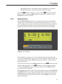
.
.
.
.
.
.
.
.
.
.
.
.
.
.
.
.
.
.
.
.
.
.
.
.
.
.
.
.
.
.
.
.
.
.
.
.
.
.
.
.
.
.
.
.
.
.
.
.
.
.
.
.
.
.
.
.
.
.
.
.
.
.
.
.
.
.
.
.
.
.
.
.
.
.
.
.
.
.
.
.
.
.
.
.
.
.
.
.
.
.
.
. 114
. 114
. 115
. 115
. 115
. 115
. 116
. 116
SYSTem:PASSword:CDISable . . . . . . . . . . . . . . .
SYSTem:PASSword:CENable <pass> . . . . . . . . . . .
SYSTem:PASSword:CENable:STATe? . . . . . . . . . . .
SYSTem:PASSword:CONVersion? [MIN|MAX|DEF] . . .
SYSTem:PASSword:CONVersion <bool>|MIN|MAX|DEF
SYSTem:PASSword:NEW <pass> . . . . . . . . . . . . .
.
.
.
.
.
.
.
.
.
.
.
.
.
.
.
.
.
.
.
.
.
.
.
.
.
.
.
.
.
.
.
.
.
.
.
.
.
.
.
.
.
.
.
.
.
.
.
.
.
.
.
.
.
.
.
.
.
.
.
.
.
.
.
.
.
.
.
.
.
.
.
.
.
.
.
.
.
.
116
116
116
117
117
117
Status Commands . . . . . . . . . . . . . . . . . . . . . . . . . . . . . . . 118
8.4.12.1
8.4.12.2
8.4.12.3
8.4.12.4
8.4.12.5
8.4.12.6
8.4.12.7
8.4.12.8
8.4.12.9
8.4.12.10
8.4.12.11
8.4.12.12
8.4.12.13
8.4.12.14
8.4.12.15
8.4.12.16
8.4.12.17
8.4.12.18
8.4.12.19
8.4.12.20
8.4.13
8.4.14
.
.
.
.
.
.
.
.
.
.
.
.
.
.
Password Commands . . . . . . . . . . . . . . . . . . . . . . . . . . . . . 116
8.4.11.1
8.4.11.2
8.4.11.3
8.4.11.4
8.4.11.5
8.4.11.6
8.4.12
.
.
.
.
.
.
.
.
.
.
.
.
.
.
Date and Time Commands . . . . . . . . . . . . . . . . . . . . . . . . . . 114
8.4.10.1
8.4.10.2
8.4.10.3
8.4.10.4
8.4.10.5
8.4.10.6
8.4.10.7
8.4.10.8
8.4.11
SYSTem:COMMunicate:SERial:BAUD? [MIN|MAX|DEF]. . . . .
SYSTem:COMMunicate:SERial:BAUD <baud>|MIN|MAX|DEF. .
SYSTem:COMMunicate:SERial:FDUPlex? [MIN|MAX|DEF] . . .
SYSTem:COMMunicate:SERial:FDUPlex <bool>|MIN|MAX|DEF.
SYSTem:COMMunicate:SERial:FEED? [MIN|MAX|DEF] . . . . .
SYSTem:COMMunicate:SERial:FEED <bool>|MIN|MAX|DEF . .
SYSTem:COMMunicate:SERial:LINefeed? [MIN|MAX|DEF] . . .
SYSTem:COMMunicate:SERial:LINefeed <bool>|MIN|MAX|DEF
SYSTem:COMMunicate:SERial:TIMe? [MIN|MAX|DEF] . . . . .
SYSTem:COMMunicate:SERial:TIMe <num>MIN|MAX|DEF . . .
SYSTem:KLOCkout? [MIN|MAX|DEF] . . . . . . . . . . . . . . .
SYSTem:KLOCkout <bool>|MIN|MAX|DEF . . . . . . . . . . . .
SYSTem:POWer:BATTery? . . . . . . . . . . . . . . . . . . . . . .
SYSTem:POWer:SOURce? . . . . . . . . . . . . . . . . . . . . . .
*CLS. . . . . . . . . . . . . . . . . . . . . . . . . . . .
*ESE? . . . . . . . . . . . . . . . . . . . . . . . . . . .
*ESE <num>|MIN|MAX|DEF . . . . . . . . . . . . . .
*ESR? . . . . . . . . . . . . . . . . . . . . . . . . . . .
*SRE? . . . . . . . . . . . . . . . . . . . . . . . . . . .
*SRE <num>|MIN|MAX|DEF . . . . . . . . . . . . . .
*STB? . . . . . . . . . . . . . . . . . . . . . . . . . . .
*TST? . . . . . . . . . . . . . . . . . . . . . . . . . . .
STATus:MEASure? . . . . . . . . . . . . . . . . . . . .
STATus:MEASure:CONDition? . . . . . . . . . . . . .
STATus:MEASure:ENABle? . . . . . . . . . . . . . . .
STATus:MEASure:ENABle <num>. . . . . . . . . . . .
STATus:OPERation? . . . . . . . . . . . . . . . . . . .
STATus:OPERation:CONDition? . . . . . . . . . . . . .
STATus:OPERation:ENABle?[MIN|MAX|DEF] . . . . .
STATus:OPERation:ENABle <num>|MIN|MAX|DEF . .
STATus:QUEStionable? . . . . . . . . . . . . . . . . . .
STATus:QUEStionable:CONDition? . . . . . . . . . . .
STATus:QUEStionable:ENABle? [MIN|MAX|DEF] . . .
STATus:QUEStionable:ENABle <num>|MIN|MAX|DEF
.
.
.
.
.
.
.
.
.
.
.
.
.
.
.
.
.
.
.
.
.
.
.
.
.
.
.
.
.
.
.
.
.
.
.
.
.
.
.
.
.
.
.
.
.
.
.
.
.
.
.
.
.
.
.
.
.
.
.
.
.
.
.
.
.
.
.
.
.
.
.
.
.
.
.
.
.
.
.
.
.
.
.
.
.
.
.
.
.
.
.
.
.
.
.
.
.
.
.
.
.
.
.
.
.
.
.
.
.
.
.
.
.
.
.
.
.
.
.
.
.
.
.
.
.
.
.
.
.
.
.
.
.
.
.
.
.
.
.
.
.
.
.
.
.
.
.
.
.
.
.
.
.
.
.
.
.
.
.
.
.
.
.
.
.
.
.
.
.
.
.
.
.
.
.
.
.
.
.
.
.
.
.
.
.
.
.
.
.
.
.
.
.
.
.
.
.
.
.
.
.
.
.
.
.
.
.
.
.
.
.
.
.
.
.
.
.
.
.
.
.
.
.
.
.
.
.
.
.
.
.
.
.
.
.
.
.
.
.
.
.
.
.
.
.
.
.
.
.
.
.
.
.
.
.
.
.
.
.
.
. 118
. 118
. 118
. 118
. 118
. 118
. 118
. 119
. 119
. 119
. 119
. 119
. 120
. 120
. 120
. 120
. 120
. 121
. 121
. 121
Statistical Calculation Types. . . . . . . . . . . . . . . . . . . . . . . . . . 122
Field Types. . . . . . . . . . . . . . . . . . . . . . . . . . . . . . . . . . . 122
v
8.4.15
8.4.16
8.4.17
Conversion Types and Parameters . . . . . . . . . . . . . . . . . . . . . . . 124
Port Numbers . . . . . . . . . . . . . . . . . . . . . . . . . . . . . . . . . 125
Date and Time Formats . . . . . . . . . . . . . . . . . . . . . . . . . . . . 126
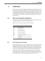
9 Calibration. . . . . . . . . . . . . . . . . . . . . . . . . . . . 127
9.1
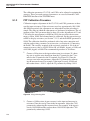
PRT and Thermistor Calibration . . . . . . . . . . . . . . . . . . 127
9.1.1
9.1.2
9.1.3
9.1.4
9.2
PRT Calibration Parameters . . . .
PRT Calibration Procedure . . . .
Thermistor Calibration Parameters
Thermistor Calibration Procedure .
.
.
.
.
.
.
.
.
.
.
.
.
.
.
.
.
.
.
.
.
.
.
.
.
.
.
.
.
.
.
.
.
.
.
.
.
.
.
.
.
.
.
.
.
.
.
.
.
.
.
.
.
.
.
.
.
.
.
.
.
.
.
.
.
.
.
.
.
.
.
.
.
.
.
.
.
.
.
.
.
.
.
.
.
.
.
.
.
127
128
129
129
Thermocouple Calibration . . . . . . . . . . . . . . . . . . . . . 130
9.2.1
9.2.2
Calibration Parameters. . . . . . . . . . . . . . . . . . . . . . . . . . . . . 130
Calibration Procedure . . . . . . . . . . . . . . . . . . . . . . . . . . . . . 131
10 Maintenance . . . . . . . . . . . . . . . . . . . . . . . . . . . 133
11 Troubleshooting . . . . . . . . . . . . . . . . . . . . . . . . . 135
11.1
Troubleshooting . . . . . . . . . . . . . . . . . . . . . . . . . . 135
11.1.1
11.1.2
11.2
11.3
Self-Test Error Messages . . . . . . . . . . . . . . . . . . . . . . . . . . . 136
Start-up Error Messages . . . . . . . . . . . . . . . . . . . . . . . . . . . . 137
Downloading Auto Logged Data . . . . . . . . . . . . . . . . . 137
CE Comments . . . . . . . . . . . . . . . . . . . . . . . . . . . 138
11.3.1
EMC Directive . . . . . . . . . . . . . . . . . . . . . . . . . . . . . . . . . 138
11.3.1.1
11.3.1.2
11.3.2
11.4
Low Voltage Directive (Safety) . . . . . . . . . . . . . . . . . . . . . . . . 139
Frequently Asked Questions . . . . . . . . . . . . . . . . . . . . 139
11.4.1
11.4.2
11.4.3
11.4.4
11.4.5
vi
Immunity Testing . . . . . . . . . . . . . . . . . . . . . . . . . . . . . . . . . . . 139
Emission Testing . . . . . . . . . . . . . . . . . . . . . . . . . . . . . . . . . . . 139
Battery .
Input . .
Logging
Output .
Other . .
.
.
.
.
.
.
.
.
.
.
.
.
.
.
.
.
.
.
.
.
.
.
.
.
.
.
.
.
.
.
.
.
.
.
.
.
.
.
.
.
.
.
.
.
.
.
.
.
.
.
.
.
.
.
.
.
.
.
.
.
.
.
.
.
.
.
.
.
.
.
.
.
.
.
.
.
.
.
.
.
.
.
.
.
.
.
.
.
.
.
.
.
.
.
.
.
.
.
.
.
.
.
.
.
.
.
.
.
.
.
.
.
.
.
.
.
.
.
.
.
.
.
.
.
.
.
.
.
.
.
.
.
.
.
.
.
.
.
.
.
.
.
.
.
.
.
.
.
.
.
.
.
.
.
.
.
.
.
.
.
.
.
.
.
.
.
.
.
.
.
.
.
.
.
.
. 139
. 140
. 141
. 141
. 142
Figures
Figure 1
Figure 2
Figure 3
Figure 4
Figure 5
Figure 6
Figure 7
Figure 8
Figure 9
Figure 10
Figure 11
Figure 12
Figure 13
Figure 14
Figure 15
Figure 16
Figure 17
Figure 18
Figure 19
Figure 20
Figure 21
Figure 22
Figure 23
Figure 24
Figure 25
Figure 26
Figure 27
Figure 28
Figure 29
Figure 30
Figure 31
Figure 32
Figure 33
Figure 34
Figure 35
Figure 36
Figure 37
Figure 38
Figure 39
Figure 40
Using the Clamp-on Ferrites . . . .
Front Panel . . . . . . . . . . . . .
Back Panel . . . . . . . . . . . . .
Thermocouple Connections . . . .
Probe Connection Wiring Diagram
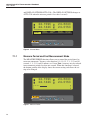
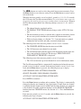
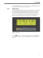
Main Menu . . . . . . . . . . . . .
Measure Period. . . . . . . . . . .
Channel Menu . . . . . . . . . . .
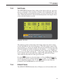
Enable Channel . . . . . . . . . .
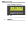
Channel Mode . . . . . . . . . . .
Moving Average . . . . . . . . . .
Display Options . . . . . . . . . .
Probe Menu . . . . . . . . . . . .
Edit Probe . . . . . . . . . . . . .
Copy Probe . . . . . . . . . . . . .
Test Probe . . . . . . . . . . . . .
Print Probe . . . . . . . . . . . . .
Default Probe. . . . . . . . . . . .
Clear Stats . . . . . . . . . . . . .
Fields Menu . . . . . . . . . . . .
Select Fields . . . . . . . . . . . .
Edit Fields . . . . . . . . . . . . .
Default Fields . . . . . . . . . . .
Display Options . . . . . . . . . .
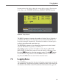
Logging Menu . . . . . . . . . . .
Demand Log Submenu . . . . . . .
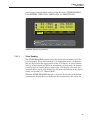
Store Readings . . . . . . . . . . .
Log History . . . . . . . . . . . .
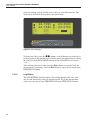
Demand Log View Data . . . . . .
Print Data. . . . . . . . . . . . . .
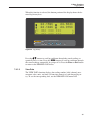
Delete Data . . . . . . . . . . . . .
Logging Options . . . . . . . . . .
Auto Log Submenu . . . . . . . .
Log Statistics (Auto Log Started) .
Start Stop . . . . . . . . . . . . . .
Auto Log View Data . . . . . . . .
Print Data. . . . . . . . . . . . . .
Delete Data . . . . . . . . . . . . .
Log Stats . . . . . . . . . . . . . .
Data Labels. . . . . . . . . . . . .
.
.
.
.
.
.
.
.
.
.
.
.
.
.
.
.
.
.
.
.
.
.
.
.
.
.
.
.
.
.
.
.
.
.
.
.
.
.
.
.
.
.
.
.
.
.
.
.
.
.
.
.
.
.
.
.
.
.
.
.
.
.
.
.
.
.
.
.
.
.
.
.
.
.
.
.
.
.
.
.
.
.
.
.
.
.
.
.
.
.
.
.
.
.
.
.
.
.
.
.
.
.
.
.
.
.
.
.
.
.
.
.
.
.
.
.
.
.
.
.
.
.
.
.
.
.
.
.
.
.
.
.
.
.
.
.
.
.
.
.
.
.
.
.
.
.
.
.
.
.
.
.
.
.
.
.
.
.
.
.
.
.
.
.
.
.
.
.
.
.
.
.
.
.
.
.
.
.
.
.
.
.
.
.
.
.
.
.
.
.
.
.
.
.
.
.
.
.
.
.
.
.
.
.
.
.
.
.
.
.
.
.
.
.
.
.
.
.
.
.
.
.
.
.
.
.
.
.
.
.
.
.
.
.
.
.
.
.
.
.
.
.
.
.
.
.
.
.
.
.
.
.
.
.
.
.
.
.
.
.
.
.
.
.
.
.
.
.
.
.
.
.
.
.
.
.
.
.
.
.
.
.
.
.
.
.
.
.
.
.
.
.
.
.
.
.
.
.
.
.
.
.
.
.
.
.
.
.
.
.
.
.
.
.
.
.
.
.
.
.
.
.
.
.
.
.
.
.
.
.
.
.
.
.
.
.
.
.
.
.
.
.
.
.
.
.
.
.
.
.
.
.
.
.
.
.
.
.
.
.
.
.
.
.
.
.
.
.
.
.
.
.
.
.
.
.
.
.
.
.
.
.
.
.
.
.
.
.
.
.
.
.
.
.
.
.
.
.
.
.
.
.
.
.
.
.
.
.
.
.
.
.
.
.
.
.
.
.
.
.
.
.
.
.
.
.
.
.
.
.
.
.
.
.
.
.
.
.
.
.
.
.
.
.
.
.
.
.
.
.
.
.
.
.
.
.
.
.
.
.
.
.
.
.
.
.
.
.
.
.
.
.
.
.
.
.
.
.
.
.
.
.
.
.
.
.
.
.
.
.
.
.
.
.
.
.
.
.
.
.
.
.
.
.
.
.
.
.
.
.
.
.
.
.
.
.
.
.
.
.
.
.
.
.
.
.
.
.
.
.
.
.
.
.
.
.
.
.
.
.
.
.
.
.
.
.
.
.
.
.
.
.
.
.
.
.
.
.
.
.
.
.
.
.
.
.
.
.
.
.
.
.
.
.
.
.
.
.
.
.
.
.
.
.
.
.
.
.
.
.
.
.
.
.
.
.
.
.
.
.
.
.
.
.
.
.
.
.
.
.
.
.
.
.
.
.
.
.
.
.
.
.
.
.
.
.
.
.
.
.
.
.
.
.
.
.
.
.
.
.
.
.
.
.
.
.
.
.
.
.
.
.
.
.
.
.
.
.
.
.
.
.
.
.
.
.
.
.
.
.
.
.
.
.
.
.
.
.
.
.
.
.
.
.
.
.
.
.
.
.
.
.
.
.
.
.
.
.
.
.
.
.
.
.
.
.
.
.
.
.
.
.
.
.
.
.
.
.
.
.
.
.
.
.
.
.
.
.
.
.
.
.
.
.
.
.
.
.
.
.
.
.
.
.
.
.
.
.
.
.
.
.
.
.
.
.
.
.
.
.
vii
12
15
16
21
22
27
28
28
30
31
32
33
34
35
42
43
44
45
46
46
47
49
50
51
52
53
54
55
56
57
58
59
59
61
61
62
63
64
65
66
Figure 41
Figure 42
Figure 43
Figure 44
Figure 45
Figure 46
Figure 47
Figure 48
Figure 49
Figure 50
viii
Default Labels . . . . . . . . . . . . . . . . . . . . . . . . . . . . . . 67
System Menu. . . . . . . . . . . . . . . . . . . . . . . . . . . . . . . 68
Comm Setup . . . . . . . . . . . . . . . . . . . . . . . . . . . . . . . 69
Date Time . . . . . . . . . . . . . . . . . . . . . . . . . . . . . . . . 71
Password . . . . . . . . . . . . . . . . . . . . . . . . . . . . . . . . . 72
Password for Calibration Access. . . . . . . . . . . . . . . . . . . . . 73
Select Calibration Channel . . . . . . . . . . . . . . . . . . . . . . . . 74
Pass Cal Reset . . . . . . . . . . . . . . . . . . . . . . . . . . . . . . 75
Serial Cable Wiring . . . . . . . . . . . . . . . . . . . . . . . . . . . 77
Using a Shorting Wire . . . . . . . . . . . . . . . . . . . . . . . . . 128
Tables
Table1
Table 2
Table 3
Table 4
Table 5
Table 6
Table 7
Table 8
Table 9
Table 10
Table 11
Table 12
Table 13
Table 14
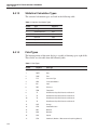
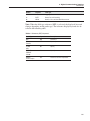
International Electrical Symbols . . . . . . . . . . . . . . . . . . . . . 1
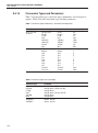
Conversion Types . . . . . . . . . . . . . . . . . . . . . . . . . . . . 36
Alphabetical List of Commands . . . . . . . . . . . . . . . . . . . . . 79
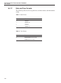
Statistical Calculation Types . . . . . . . . . . . . . . . . . . . . . . 122
Field Types . . . . . . . . . . . . . . . . . . . . . . . . . . . . . . . 122
Reference (REF) Keywords. . . . . . . . . . . . . . . . . . . . . . . 123
Conversion Types, Mnemonics, and Serial Port Responses . . . . . . 124
Conversion Types and Parameters . . . . . . . . . . . . . . . . . . . 124
RJC Settings . . . . . . . . . . . . . . . . . . . . . . . . . . . . . . 125
Port Numbers . . . . . . . . . . . . . . . . . . . . . . . . . . . . . . 125
Date Formats . . . . . . . . . . . . . . . . . . . . . . . . . . . . . . 126
Time Formats . . . . . . . . . . . . . . . . . . . . . . . . . . . . . . 126
PRT and Thermistor Calibration Parameter Description . . . . . . . . 127
Calibration Parameters . . . . . . . . . . . . . . . . . . . . . . . . . 131
ix
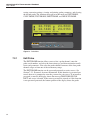
1 Before You Start
Symbols Used
1
1.1
Before You Start
Symbols Used
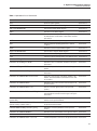
Table 1 lists the symbols that may be used on the instrument or in this manual
Table1 International Electrical Symbols
and the meaning of each symbol.
Symbol
Description
AC (Alternating Current)
AC-DC
Battery
Complies with European Union Directives
DC (Direct Current)
Double Insulated
Electric Shock
Fuse
PE Ground
Hot Surface (Burn Hazard)
Read the User’s Manual (Important Information)
Off
1
1529 Chub-E4 Thermometer Readout
User’s Guide
Symbol
Description
On
Canadian Standards Association
OVERVOLTAGE (Installation) CATEGORY II, Pollution Degree 2 per IEC1010-1 refers to the level of Impulse Withstand Voltage protection provided. Equipment of
OVERVOLTAGE CATEGORY II is energy-consuming equipment to be supplied from
the fixed installation. Examples include household, office, and laboratory appliances.
C-TIC Australian EMC mark
The European Waste Electrical and Electronic Equipment (WEEE) Directive
(2002/96/EC) mark.
1.2
Safety Information
Use this instrument only as specified in this manual. Otherwise, the protection
provided by the instrument may be impaired. Refer to the safety information in
Sections 1.2.1 and 1.2.2.
The following definitions apply to the terms “Warning” and “Caution”.
• “Warning” identifies conditions and actions that may pose hazards to the
user.
• “Caution” identifies conditions and actions that may damage the instrument being used.
1.2.1
Warnings
• DO NOT use this unit in environments other than those listed in the
User’s Guide.
• Follow all safety guidelines listed in the User’s Guide.
• Calibration equipment should only be used by trained personnel.
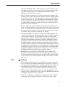
• This instrument can measure extreme temperatures. Precautions must be
taken to prevent personal injury or damage to objects. Probes may be extremely hot or cold. Cautiously handle probes to prevent personal injury.
Carefully place probes on a heat/cold resistant surface or rack until they
reach room temperature.
• If this equipment is used in a manner not specified by the manufacturer,
the protection provided by the equipment may be impaired.
• Before initial use, or after transport, or after storage in humid or semi-humid environments, or anytime the instrument has not been energized for
more than 10 days, the instrument needs to be energized for a "dry-out"
period of 2 hours before it can be assumed to meet all of the safety re-
2
1 Before You Start
Safety Information
quirements of the IEC 1010-1. If the product is wet or has been in a wet
environment, take necessary measures to remove moisture prior to applying power such as storage in a low humidity temperature chamber
operating at 50°C for 4 hours or more.
• The AC adapter can present safety concerns if misused or damaged. To
avoid the risk of electric shock or fire, do not use the AC adapter outdoors
or in a dusty, dirty, or wet environment. If the cord, case, or plug of the
adapter is damaged in any way, discontinue its use immediately and have
it replaced. Never disassemble the AC adapter. Use only the AC adapter
provided with the instrument or equivalent adapter recommended by the
manufacturer of this instrument.
• The AC adapter has circuits with high voltage inside that could present
danger of electrical shock or fire if exposed. If the AC adapter is damaged
in any way or becomes hot, discontinue its use immediately, disconnect it
from any AC supply, and have it replaced. Do not attempt to open, repair,
or continue using a damaged or defective AC adapter.
• The instrument batteries can present danger if not handled properly. To
avoid the risk of exposure to dangerous substances or explosion, immediately remove the batteries and discontinue use if they leak or become
damaged. Never allow the batteries to be shorted, heated, punctured, or
dropped. If the instrument is physically damaged, immediately remove
the batteries to insure that they do not become shorted. While removed
from the instrument, store the batteries in a location so that they do not
come into contact with metal or fluids that might short circuit the batteries
and where they are safe from excessive temperatures. Used batteries must
be disposed of properly. Check your local regulations for additional information. Never dispose of batteries in fire which may result in explosion
with the possibility of personal injury or property damage.
• DO NOT use this instrument in combination with any probe ( PRT,
thermistor, or thermocouple) to measure the temperature or resistance of
any device where the probe might come in contact with a conductor that
is electrically energized. Severe electric shock, personal injury, or death
may occur.
1.2.2
Cautions
• If the instrument is dropped, struck, or handled in a way that causes internal or external physical damage, immediately unplug the AC adapter, remove the batteries, discontinue use, and contact the factory for repair. Do
not attempt to disassemble or repair the instrument, batteries, or AC
adapter. Refer repairs or replacement components to the manufacturer.
• The instrument and thermometer probes are sensitive and can be easily
damaged. Always handle these devices with care. DO NOT allow them to
be dropped, struck, stressed, or overheated.
• Probes are fragile devices which can be damaged by mechanical shock,
overheating, and absorption of moisture or fluids in the wires or hub.
3
1529 Chub-E4 Thermometer Readout
User’s Guide
Damage may not be visibly apparent but nevertheless can cause drift, instability, and loss of accuracy. Observe the following precautions:
• DO NOT allow probes to be dropped, struck, bent, or stressed.
• DO NOT overheat probes beyond their recommended temperature range.
• DO NOT allow any part of the probe other than the sheath to be immersed in fluid.
• DO NOT allow the probe hub or wires to be exposed to excessive temperatures.
• Keep the probe wires clean and away from fluids.
1.3
Authorized Service Centers
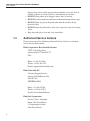
Please contact one of the following authorized Service Centers to coordinate
service on your Hart product:
Fluke Corporation, Hart Scientific Division
799 E. Utah Valley Drive
American Fork, UT 84003-9775
USA
Phone: +1.801.763.1600
Telefax: +1.801.763.1010
E-mail: [email protected]
Fluke Nederland B.V.
Customer Support Services
Science Park Eindhoven 5108
5692 EC Son
NETHERLANDS
Phone: +31-402-675300
Telefax: +31-402-675321
E-mail: [email protected]
Fluke Int'l Corporation
Service Center - Instrimpex
Room 2301 Sciteck Tower
22 Jianguomenwai Dajie
Chao Yang District
4
1 Before You Start
Authorized Service Centers
Beijing 100004, PRC
CHINA
Phone: +86-10-6-512-3436
Telefax: +86-10-6-512-3437
E-mail: [email protected]
Fluke South East Asia Pte Ltd.
Fluke ASEAN Regional Office
Service Center
60 Alexandra Terrace #03-16
The Comtech (Lobby D)
118502
SINGAPORE
Phone: +65 6799-5588
Telefax: +65 6799-5588
E-mail: [email protected]
When contacting these Service Centers for support, please have the following
information available:
• Model Number
• Serial Number
• Voltage
• Complete description of the problem
5
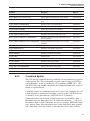
2 Introduction
2
Introduction
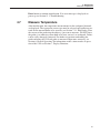
The Hart 1529 is a low-cost, high-accuracy, digital thermometer readout designed to be used with 25 and 100Ω PRTs, thermistors, and thermocouples. Its
unique combination of features makes it suitable for a wide variety of applications from laboratory measurement to industrial processes. Features of the 1529
include:
• Measures 25Ω and 100Ω PRTs, thermistors, and thermocouples
• Four inputs: two PRT/thermistor and two thermocouple (standard configuration)
• Four-wire connection eliminates lead resistance effects in PRTs
• Three-wire measurement mode for three-wire RTDs
• Exclusive patented mini-DWF connectors (U.S. Patent No. 5,964,625)
• Automatic current reversal eliminates thermoelectric EMF errors
• Accuracy: PRTs to 0.006°C, thermistors to 0.002°C, and thermocouples
to 0.3°C
• Typical resolution: PRTs 0.001°C, thermistors 0.0001°C, thermocouples
0.01°C
• Measures four sensors simultaneously with a fast one-second measurement cycle
• Measures one sensor at 10 readings per second (limited accuracy)
• Adjustable moving average for extra precision
• Stores over 8,000 measurements internally
• Accepts ITS-90, PT-100 (ASTM E1137, DIN 43760, or IEC-751), and
Callendar-Van Dusen PRT characterizations
• Accepts Steinhart-Hart R(T) or T(R) and YSI-400 type thermistor characterizations
• Accepts thermocouple types B, E, J, K, N, R, S, T, Au-Pt, and polynomial
specified
• Temperature offsets for improved thermocouple accuracy
• Stores 10 additional sets of probe parameters
• Eight programmable display sets for display probe information, measurement statistical data, or difference between measurements
• Password protection of settings
• Large, LCD, user-configurable, display viewable in bright or dim lighting
• Serial RS-232 interface standard; IEEE-488 GPIB interface optional
• Powered by external AC supply, 12-15V DC source, or internal rechargeable battery
7
3 Specifications and Environmental Conditions
Specifications
3
3.1
Specifications and Environmental
Conditions
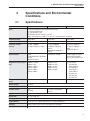
Specifications
PRT
Inputs
Thermistor
Thermocouple
2 channels PRT/thermistor and 2 channels thermocouple
or 4 channels PRT/thermistor
or 4 channels thermocouple
PRT/thermistor channels accept 2,3, or 4 wires
Thermocouple channels accept B, E, J, K, N, R, S, T, and Au-Pt thermocouple types
Temperature Range1
–189 to 960°C
–50 to 150°C
–270 to 1800°C
Measurement Range
0 to 400Ω
0 to 500kΩ
–10 to 100 mV
Resistance / Voltage
Accuracy2
0 to 20Ω : ±0.0005Ω
20 to 400Ω: ±25 ppm of reading
0 to 5kΩ: ±0.0005kΩ
5 to 200kΩ: ±100 ppm of
reading
200 to 500 KΩ: ±300 ppm of
reading
–10 to 50 mV: ±0.005 mV
50 to 100 mV: ±100 ppm of
reading
(Internal RJC: ±0.25°C)
Characterizations
ITS-90,
PT-100 (ASTM E1137, DIN 43760,
IEC-751),
Callendar-Van Dusen
Steinhart-Hart, YSI-400
NIST Monograph 175, 3-point
deviation function applied to
NIST 175, 6th-order polynomial
Temperature Accuracy (meter ±0.004°C at –100°C
only)1
±0.006°C at 0°C
±0.009°C at 100°C
±0.012°C at 200°C
±0.018°C at 400°C
±0.024°C at 600°C
±0.0025°C at 0°C
±0.0025°C at 25°C
±0.004°C at 50°C
±0.010°C at 75°C
±0.025°C at 100°C
Type
B
E
J
K
N
R
S
T
Temperature Resolution,
typical3
0.001°
0.0001°
0.01 to 0.001°
Operating Range1
16 to 30°C
Measurement Interval
0.1 second to 1 hour; inputs may be read sequentially or simultaneously at 1 second or greater interval
Excitation Current
1mA
(reversing)
Display
1.3” x 5" backlit LCD graphical display
Display Units
°C, °F, K, Ω, KΩ, mV
Data Logging
Up to 8,000 time- and date-stamped measurements can be logged
Logging Intervals
0.1, 0.2, 0.5, 1, 2, 5, 10, 30, or 60 seconds; 2, 5, 10, 30, or 60 minutes
Averaging
Moving average of most recent 2 to 10 readings, user selectable
Statistical Data
Average, standard deviation, minimum, maximum, spread, N, difference (delta)
2 and 10 μA, automatically
selected
Ext./Int.RJC
±0.6°C/±0.6°C
±0.07°C/±0.25°C
±0.1°C/±0.35°C
±0.15°C/±0.4°C
±0.15°C/±0.3°C
±0.4°C/±0.5°C
±0.5°C/±0.6°C
±0.1°C/±0.3°C
N/A
9
1529 Chub-E4 Thermometer Readout
User’s Guide
PRT
Thermistor
Thermocouple
Probe Connection
Patented DWF connectors accepts spade lug, bare-wire, or banana
plug terminations
Universal receptacle accepts
miniature and standard
connectors
Communications
RS-232 port included, IEEE-488 (GPIB) optional
AC Power
100 to 240 VAC, 50-60 Hz, 0.4A
DC Power
12 to 16 VDC, 0.5 A (battery charges during operation from 14.5 to 16 VDC, 1.0A)
Battery
NiMH, 8 hours operation typical without backlight, 3 hours to charge, 500 cycles
Size
4.0” H x 7.5” W x 8.2” D (102 x 191 x 208 mm)
Weight
4.5 lbs. (2 kg)
1The
sensor generally limits the actual temperature range. Temperature accuracy specifications do not include sensor accuracy. Thermistor temperature accuracy assumes a 10kΩ sensor. Thermocouple accuracy is with internal reference junction compensation; accuracy is
improved with external reference junction compensation. Thermocouple temperature accuracies are given for external reference junction
compensation and internal reference junction compensation, respectively.
2Measurement accuracy specifications apply within the operating temperature range and assume 4-sample averaging and 4 lead wires for
PRTs. With 3-wire RTDs add 0.05Ω to the measurement accuracy plus the maximum possible difference between the resistances of the
lead wires.
3Actual
resolution can be set greater than typical resolution, but the added digits (0.0001 max.) may not be meaningful to the measurement.
3.2
Environmental Conditions
Although the instrument has been designed for optimum durability and trouble-free operation, it must be handled with care. The instrument should not be
operated in an excessively dusty, dirty, or wet environment. Maintenance and
cleaning recommendations can be found in the Maintenance section of this
manual.
For full accuracy, operate the instrument in ambient temperatures between
16–30°C (61–86°F). The battery may not charge properly at temperatures
above 30°C. Do not operate the instrument in an environment colder than 5°C
(41°F) or warmer than 40°C (104°F).
The instrument operates safely under the following conditions:
• Ambient temperature range: absolute 5–40°C (41–104°F) [full accuracy
16–30°C (61–86°F)]
• Ambient relative humidity: maximum 80% for temperature <31°C, decreasing linearly to 50% at 40°C
• Pressure: 75 kPa–106 kPa
• Vibration should be minimized
• Altitude less than 2,000 meters
• Indoor use only
10
4 Quick Start
Unpacking
4
Quick Start
This section briefly explains the basics of setting up and operating your 1529
Thermometer Readout.
4.1
Unpacking
Carefully unpack the 1529 thermometer readout. Verify that the following
items are present:
• 1529 Thermometer Readout (The battery inside the 1529 is completely
charged when shipped. Initial charging is not required.)
• AC Adapter/Charger and power cord
• Serial Cable
• User’s Guide
• Report of Calibration with calibration label
• Probe (optional-must be purchased separately)
• Two ferrites (for use with probes as described in Section 4.4.1, Using the
Clamp-on Ferites)
If all items are not present, contact an Authorized Service Center (see Section
1.3)
4.2
Use Proper Care
You must understand the safety issues related to the 1529. Be aware that potential hazards exist due to high temperatures and battery chemicals. Carefully
read the Warnings in Section 1.2.1 and Cautions in Section 1.2.2.
The 1529 and any thermometer probes used with it are sensitive instruments
that can be easily damaged. Always handle these devices with care. DO NOT
allow them to be dropped, struck, stressed, or over-heated.
4.3
Learn About the Features and Components
Familiarize yourself with the features and accessories of the 1529 by reading
Section 5, Parts and Controls.
4.4
Connect the Probe
The PRT/thermistor or thermocouple probe connects on the back panel of the
1529 using patented mini-DWF connectors (PRT/thermistor) or the universal
receptacles (thermocouples).
11
1529 Chub-E4 Thermometer Readout
User’s Guide
4.4.1
Using the Clamp-on Ferrites
Clamp-on ferrites are provided with this product for the use of improving its
electromagnetic (EM) immunity in environments of excessive EM interference.
During EMC testing we found that ferrites clamped around the probe cables
and power cord reduced the risk that EM interference affects measurements.
Therefore, we recommend that the clamp-on ferrites provided (Steward P/N
28A2025-0A2) be used on the cables of probes attached to this product, especially if it the product is used near sources of EM interference such as heavy industrial equipment.
To attach a ferrite to a probe cable, make a loop in the cable near the connector
and clamp the ferrite around half of the loop as shown in Figure 1. The ferrite
can be easily snapped open and moved to a new probe when needed.
probe cable
clamp-on ferrite
Figure 1 Using the Clamp-on Ferrites
4.5
Connect the Power Source
The 1529 draws power from either a 15-volt DC power supply (the included
AC adapter) connected to the DC input or the internal re-chargeable battery
pack. To use the AC adapter, plug it into a wall outlet of the appropriate voltage
and insert the DC plug into the DC power input of the 1529 (see Figure 3 on
page 16.)
4.6
Switch the Power On
Power is turned on and off with the power switch located on the top right corner of the back panel. To switch the power on, toggle the power switch to the
‘ON’ position. To switch power off, toggle the power switch to the ‘OFF’ position. The instrument takes a few seconds to power up, initialize, and begin normal operation. A self-test is performed displaying the channel configuration
and status of the system, calibration, GPIB, memory, and buttons. If the thermometer readout calibration has expired, the user is notified and must press the
12
4 Quick Start
Measure Temperature
Enter button to continue initialization. If an error message is displayed on
power up see Section 11.1, Troubleshooting.
4.7
Measure Temperature
After initialization, the temperature measurements for the configured channels
are displayed. The appropriate sensor type must be selected and coefficients entered for the measurements to be accurate (see Section 7.2.1, Edit Probe). Place
the sensors of the probe into the object(s) you want to measure. DO NOT force
the probe(s) or otherwise allow them to be bent, stressed, or overheated. Probes
can be easily damaged if misused. For further suggestions on handling the
probe and using the 1529 and probe to measure temperature accurately, see
Section 6, General Operation. For information on the various modes of operation of the 1529 see Section 7, Display Functions.
13
5 Parts and Controls
Front Panel Buttons
5
Parts and Controls
The functions of the various features of the 1529 are described below.
5.1
Front Panel Buttons
The front panel buttons Enter/Menu, Unit, Contrast, and Exit are used to select and alter the functions of the thermometer readout (see Figure 2).
24.159C
24.142C
1
3
4
1 TYP: CVD
1 SER: 145-560
1 –T1:
0.0000 C
ALOG: OFF 0%
1529
24.634C
24.015C
2
1 AVE: 24.1530 C
1 STD:
0.0038 C
1 SPR:
0.0219 C
TIME: 14:58:43
CHUB E-4 THERMOMETER READOUT
ENTER / MENU
UNIT
CONTRAST
EXIT
Figure 2 Front Panel
The function of each button is as follows:
Enter/Menu - This button displays and scrolls through the menu options. Use
this button to select the menu to enter and to save changes made to menu
choices.
Unit - LR Use these buttons to select the units C, F, or K when not in the
menu structure. In conjunction with the Menu button, use these buttons to
scroll left and right through menu options and choices.
Contrast -UD Use these buttons to lighten or darken the display when not in
the menu structure. In conjunction with the Menu button, use these buttons to
scroll up and down through menu options and choices.
Exit - Use this button to exit any menu. When editing a parameter, if the Exit
button is pressed, the immediate operation is canceled and control skips to the
next parameter. Holding the button down for several seconds, exits to the main
display.
15
1529 Chub-E4 Thermometer Readout
User’s Guide
Figure 3 Back Panel
16
5 Parts and Controls
Back Panel
5.2
Back Panel
The back panel consists of the power switch, AC adapter connector, charging
indicator, RS-232 port connector, IEEE-488 port connector (optional), serial label, and probe connectors. The 1529 thermometer readout can be configured in
three different ways. The configuration affects the probe connectors on the
back panel. The Model 1529 is configured with one PRT/thermistor input module of two channels and one thermocouple input module of two channels. The
Model 1529-R is configured with two PRT/thermistor input modules of four
channels. The Model 1529-T is configured with two thermocouple input modules of four channels. Figure 3 shows the back panel and the three different
configurations.
Power Switch - The power switch turns the thermometer readout on and off.
AC Adapter Connecor - The AC adapter plugs into the DC power input to recharge the battery and to power the instrument while the battery is being
charged (see Section 6.3, Battery).
Charging Indicator - The charging indicator lights when the AC adapter is
connected. It glows green when the battery is at full charge and amber when the
battery is being charged.
RS-232 Port Connector - The DB-9 connector is for interfacing the thermometer readout to a computer or terminal with serial RS-232 communications.
IEEE-488 Port (optional) - The GPIB connector is for interfacing the thermometer readout to a computer or terminal with IEEE-488 communications.
Serial Label - The serial label shows the instrument model and serial number.
Probe Connectors - Probe(s) must be connected either to the patented
mini-DWF connectors (PRT/thermistor probes) or to the universal receptacle
(thermocouples) for operation.
5.3
Accessories
The 1529 thermometer readout comes standard with a hand strap on the side
for easy carrying of the instrument. The following accessories are also
available:
• 2513-1529 Rack Mount Kit
• 9323 Soft Carrying Case
• 9322 Hard Carrying Case
• 2380 Small Thermocouple Connector Kit
• 2381 Large Thermocouple Connector Kit
17
6 General Operation
Display
6
General Operation
This section explains basic operation of the 1529 thermometer readout. Detailed operation of the 1529 is explained in Sections 7 and 8. Section 7 explains
the menu structure and the functions available in the menu structure and Section 8 explains the communications interface for operating the 1529 remotely.
6.1
Display
The 1529 display consists of two parts. The top portion of the display is used
for displaying the measurements from one to four inputs. The bottom portion of
the display is reserved for the programmable fields and field display sets. Information about the channels and measurements can be displayed in greater detail
such as min, max, spread, standard deviation, and many other functions. When
the measure period is 0.1 or 0.2 seconds (fast measurement mode), the programmable fields and field display set information are not displayed.
6.2
Changing Units
The 1529 thermometer readout is capable of displaying temperature in Celsius
(C), Fahrenheit (F), or Kelvin (K). (Displaying in units of Ω, KΩ, or mV is also
available through the PROBE menu and is channel specific.) Temperature units
are changed on all channels (not individually) by pressing the buttons on the
front panel when not in the menu structure. Press the Unit, LR, buttons to
scroll forward and backward through C, F, or K. All channels or fields that are
displaying temperature on the upper or lower display are updated to the new
units.
Channels that are set to Ω, KΩ, or mV in the PROBE menu are left unchanged
when temperature units are modified. Changing the units resets the statistical
calculations (displayed in the bottom portion of the display).
6.3
Battery
The 1529 thermometer readout has a built-in nickel-metal-hydride battery pack
that can power the instrument for about eight hours before needing to be recharged. The battery discharges more quickly when the display backlight is
used. The percent of battery charge remaining is displayed on the bottom portion of the display when the battery power is being used. The battery percentage is approximate and should only be used as a general guideline when
determining the length of charge remaining. The battery is recharged in situ
(while in place) using the AC adapter that is provided.
Plug the AC adapter into the wall outlet and connect the DC plug of the adapter
into the 1529. The battery is charged as necessary whether or not the instrument is switched on. The power control circuit inside the instrument manages
battery charging and stops charging the battery automatically when the battery
19
1529 Chub-E4 Thermometer Readout
User’s Guide
is fully charged. Only charge the battery when ambient temperature is between
16°C and 30°C (61°F and 86°F) It normally takes about three hours to fully
charge the battery. The instrument can be operated while the battery is being
charged. The charging indicator on the back panel is green when the battery is
fully charged and amber when being charged using the AC adapter.
The battery may self-discharge over several months, especially if the temperature is warm. The battery pack can be used for a minimum of 500 charge-discharge cycles before needing to be replaced. Replacement battery packs are
available from the manufacturer. The battery pack can be easily removed and
replaced in the field by following this procedure:
1.
Power the 1529 off and unplug the AC adapter from the unit.
2.
Turn the 1529 over to expose the battery compartment. Remove the battery cover hex screw. Place the screw in a safe place so it won’t get lost.
Flip open the battery cover to reach the battery pack.
3.
Remove the battery pack. Gently disconnect the battery plug connector.
4.
Attach the polarized plug of the new battery pack onto the connector.
Note: The battery plug is polarized and can only be plugged in one direction. DO NOT force it. Place the battery pack in the battery
compartment.
5.
Close the battery cover and replace the screw. Avoid pinching the battery
wires.
6.
Plug in the AC adapter and charge for a minimum of four hours for the
initial charge. Used batteries must be disposed of properly. Check your
local regulations for additional information. You may return used batteries to the manufacturer. Never dispose of batteries in fire as this may result in an explosion with the possibility of personal injury or property
damage.
When the battery charge is not at 100%, the measurement accuracy is not affected. If the power is interrupted while the instrument is logging measurements (on demand or automatically), the logged data is preserved and logging
resumes when the power is restored.
6.4
Probe Input Modules
The 1529 can be configured in three ways:
• Two RTD/thermistor input modules.
• Two thermocouple input modules.
• One RTD/thermistor and one thermocouple input module.
Each input module supports two channels. Your 1529 thermometer readout is
configured at the factory and is not field changeable. Input modules should
never be removed for any reason.
20
6 General Operation
Probe Input Modules
All possible configurations are shown in Figure 3 on page 16.
6.4.1
Connecting a PRT or Thermistor Probe
PRT and thermistor probes are attached to the resistance input module via Hart
Scientific mini-DWF connectors. These patented connectors accept bare wire,
spade, or mini banana plug terminations. The connectors are color coded for
ease in connecting lead-wires.
When using 2- and 3-wire sensors, the accuracy of the 1529 is reduced as
stated in the specifications. Compensation is made for 3-wire PRTs, but the difference in lead resistance affects the measurement accuracy. The 1529 thermometer readout is unable to compensate for 2-wire lead resistance.
Attach the lead-wires of the probes as shown in Figure 5 on page 22. The top
termainals sense current and the bottom terminals sense potential.
6.4.2
Connecting a Thermocouple
The 1529 thermocouple input module accepts both standard and sub-miniature
size thermocouple connectors. The connection is made with the positive terminal on the right and the negative terminal on the left. You must use a connector
that matches the thermocouple type for the internal RJC to be accurate. For example, if you are using a type K thermocouple you must also use a type K connector, which is made from the same type of metal. For best results, wait two
minutes before measuring after inserting the thermocouple connector into the
input module.
Figure 4 Thermocouple Connections
21
1529 Chub-E4 Thermometer Readout
User’s Guide
Channel 1
Channel 2
Shield
Connecting 4-wire probes
Channel 1
Channel 2
Connecting 3-wire probes
Channel 1
Channel 2
Connecting 2-wire probes
Figure 5 Probe Connection Wiring Diagram
22
6 General Operation
DC Power Source
6.5
DC Power Source
Caution: For CE compliance and for performance, use only the AC
adapter shipped with the instrument by Hart Scientific. If the AC adapter
needs to be replaced, contact an Authorized Service Center (see Section
1.3).
The DC power source provides power to charge the battery. It can also be used
to power the 1529 while the battery is being charged. The AC adapter provided
with the 1529 is intended for these purposes. The DC power source plugs into
the DC power input on the back panel of the instrument. The AC adapter has
circuits with high voltages inside that could present danger of electric shock or
fire if exposed. If the AC adapter is damaged in any way or becomes hot, discontinue use immediately, disconnect the adapter from any AC supply, and replace the adapter. Do not attempt to open, repair, or continue using a damaged
or defective AC adapter.
6.6
Power On Self-Test
When power is turned on, the 1529 performs a self-test checking the system, all
channels, calibration, GPIB, memory, and buttons. If an error occurs, an error
message is displayed. See Section 11.1, Troubleshooting for additional information on error messages.
6.7
Display Backlight and Contrast
The display backlight is adjustable for use in varying lighting conditions. The
four backlight modes are accessible in the CHANNEL menu DISPLAY OPTIONS function. If the display appears faded, dark, or blank, adjust the contrast (off, low, medium, high) using the front panel contrast buttons.
6.8
Taking Measurements
The procedure for configuring the 1529 thermometer readout to take measurements on a particular input channel requires the following: (1) connecting the
sensor to the appropriate input channel , (2) enabling the channel, and (3) selecting the conversion type and probe characterization values.
6.8.1
Connecting the Sensor
Connect the sensor to the RTD/Thermistor channel(s) or thermocouple channel(s) that you want to measure. Refer to Section 7.4, Probe Input Modules, for
additional information.
23
1529 Chub-E4 Thermometer Readout
User’s Guide
6.8.2
Enabling the Channel
Channels are set first by selecting either simultaneous or scan mode in the
CHANNEL menu CHANNEL MODE function. Simultaneous mode shows one
to four channels in the upper display simultaneously. Scan mode shows one
channel at a time (in large digit format) scanning through one to four channels
depending on the channels that are enabled. After the mode has been selected,
use the CHANNEL menu ENABLE CHANNEL function, to select the channel
to be displayed. Any channel set to ‘Off’ is not displayed. See Sections 7.1.3,
Channel Mode, and 7.1.2, Enable Channel, for more information.
6.8.3
Selecting Conversion Type and Probe Characterization
Before the 1529 can accurately measure temperature, it must be configured to
calculate temperature from the resistance or voltage of the sensor. There are
many temperature conversion algorithms available and the one to use depends
on the type of sensor and its calibration. Many conversion algorithms use coefficients that characterize the sensor. Coefficients are determined when the sensor is calibrated. SPRTs and RTDs often use the ITS-90 algorithms and are
provided with ITS-90 characterization coefficients. Thermistors often use the
Steinhart-Hart algorithms and coefficients. Thermocouples use standard tables
or equations depending on its type. For additional information on conversion
types, see Section 7.2, Probe Menu.
The conversion type and characterization coefficients for a sensor are specified
using the PROBE menu EDIT PROBE function (see Section 7.2.1).
6.9
Fast Measurement Mode
Fast Measurement Mode applies to measure periods of 0.1, 0.2, or 0.5 seconds.
This mode allows measurements to be displayed or logged quickly.
Normally, when each measurement is made a self-calibration of the measurement circuit is performed simultaneously during the measurement process to
offset errors from component drift and spurious EMFs. For measure periods of
0.1, 0.2, and 0.5 seconds, the fast measurement rate is achieved by foregoing
the self-calibration. The drawback to this Fast Measurement Mode is the accuracy of the measurement may be poor and subject to drift. Accuracy can be
temporarily improved using the AUTO-CAL function that appears in the
CHANNEL menu when in this Fast Measurement Mode. The AUTO-CAL
function causes the instrument to perform a single self-calibration of the measurement circuit then resume fast measuring (without automatic
self-calibration).
See Section 8.1.1 for detailed information on using the Fast Measurement
Mode.
24
6 General Operation
Data Logging
6.10
Data Logging
Data can be logged either on demand or automatically at a user-selected interval. When data is logged, readings are stored to the instrument's memory and
assigned a label for easy recall and organization of data. Up to 100-demand log
and 8,160 auto log readings can be stored. When data is being logged, the left
bottom corner of the main display shows a strip-recorder indicator.
25
7 Menu Functions
Channel Menu
7
Menu Functions
Selecting the Enter/Menu button from the front panel accesses the main menu
of the 1529 thermometer readout. The main menu consists of the submenus:
CHANNEL, PROBE, FIELDS, LOGGING, and SYSTEM. Each submenu
has its own set of functions. The Enter/Menu button is used to select and save
menu choices. The Unit LR buttons are used to scroll forward or backward
through the functions. The Exit button is used to return from a function to the
previous menu or step through parameters.
24.159C
24.142C
1
3
2
4
24.634C
24.015C
LR to select menu item. Press ENTER.
CHANNEL
1529
PROBE
FIELDS
LOGGING
SYSTEM
CHUB E-4 THERMOMETER READOUT
ENTER / MENU
UNIT
CONTRAST
EXIT
Figure 6 Main Menu
7.1
Channel Menu
The CHANNEL menu provides functions for setting the measurement period,
selecting channels, setting the channel display mode, and setting measurement
averaging. The functions that appear in the CHANNEL menu are MEASURE
PERIOD, ENABLE CHANNEL, CHANNEL MODE, MOVING AVERAGE,
27
1529 Chub-E4 Thermometer Readout
User’s Guide
and DISPLAY OPTIONS/AUTO-CAL. (The DISPLAY OPTIONS changes to
AUTO-CAL when the measure period is less than 1 second.)
1
3
24.159C
24.142C
2
4
24.634C
24.015C
MEASUREMENT CONTROL FUNCTIONS
ENABLE
CHANNEL
MEASURE
PERIOD
1529
CHANNEL
MODE
MOVING
AVERAGE
DISPLAY
OPTIONS
CHUB E-4 THERMOMETER READOUT
ENTER / MENU
UNIT
CONTRAST
EXIT
Figure 8 Channel Menu
7.1.1
Measure Period and Fast Measurement Mode
The MEASURE PERIOD function allows you to control the period (time) between measurements. You may select between 0.1, 0.2, 0.5, 1, 2, 5, 10 and 30
seconds, 1, 2, 5, 10, and 30 minutes, or 1 hour. Note: Accuracy may be reduced
in measurement periods less than one second. When this function is selected,
the bottom portion of the display shows the current setting and allows the setting to be changed.
1
3
24.159C
24.142C
MEA PER:
4
24.634C
24.015C
1 SEC
1529
CHUB E-4 THERMOMETER READOUT
ENTER / MENU
Figure 7 Measure Period
28
2
UNIT
CONTRAST
EXIT
7 Menu Functions
Channel Menu
The LR buttons are used to select the period between measurements. Press
the Enter button to save the new setting. Press the Exit button to cancel and to
exit to the menu.
When the measure period is set to less than 1 second (i.e. 0.1, 0.2, 0.5 seconds)
the 1529 enters the Fast Measurement Mode. The menu buttons may seem to be
sluggish in this mode as the processor is making faster measurements. When in
the Fast Measurement Mode, the following changes occur at 0.1, 0.2, and 0.5
seconds.
• The channel display is updated quicker.
• The DISPLAY FUNCTIONS function changes to the AUTO-CAL function.
• The measurement accuracy is reduced and is subject to uncertainty factors
that are not typically introduced in a normal full measurement cycle.
• With serial port printing (see Section 7.5.1.1) measurements are printed
without the time and date and other associated information.
The following occur if the measure period is set to 0.1 or 0.2 seconds.
• The CHANNEL MODE function becomes unavailable.
• The 1529 measures one channel in scan mode.
• The field information normally displayed in the bottom portion of the display is not updated or displayed. The message, FIELD DATA NOT
AVAILABLE AT THIS RATE, is displayed.
The following occur if the measure period is set to 0.5 seconds.
• The 1529 can measure up to four channels in scan or simultaneous mode.
The Fast Measurement Mode is automatically implemented when the measure
period is set to less than 1 second. If the measure period is set to 0.1 or 0.2 seconds and the Enter button is pressed, the following message is display.
ONE CHANNEL ONLY. SETTINGS CHANGED.
SELECT CHANNEL USING ENABLE CHANNEL.
ACCURACY NOT GUARANTEED AT THIS RATE.
Press ENTER to continue …
Press the Enter button to confirm and to continue. The display is automatically
changed to display one channel in large digit format. If more than one channel
is enabled, the first channel is left enabled and the other channels are automatically disabled. To enable a different channel, use the ENABLE CHANNEL
function from the CHANNEL menu. See Section 8.1.2. Press the Exit button
to cancel.
If the measure period is set to 0.5 seconds and the Enter button is pressed, the
following message is display.
ACCURACY NOT GUARANTEED AT THIS RATE.
29
1529 Chub-E4 Thermometer Readout
User’s Guide
Press ENTER to continue …
Press the Enter button to confirm and to continue. The display is remains unchanged and all enabled channels remain enabled channels. Press the Exit button to cancel.
When the measure period is reset to 1 second or greater, the following message
is displayed indicating that the 1529 is returning to normal operation.
FULL ACCURACY.
The DISPLAY FUNCTIONS function of the CHANNEL menu reappears and
the CHANNEL MODE function is available.
Note: Accuracy in the Fast Measurement Mode is affected by ambient conditions, changes in measured temperature, higher measured temperature, and the
time duration from using the AUTO-CAL function. To reduce the uncertainty
in the Fast Measurement Mode, use the 1529 in a controlled ambient environment, in a very stable bath or dry block at lower temperatures, and use the
AUTO-CAL function often.
7.1.2
Enable Channel
The ENABLE CHANNEL function enables and disables measuring of each
channel. If a channel is off, its measurement is not displayed on the top portion
of the display in either scan or simultaneous display modes. When this function
is selected, the bottom portion of the display shows the on/off status of each
configured channel and allows the setting to be changed. Each configured channel is identified by its channel number.
1
3
CHAN
CHAN
CHAN
CHAN
24.159C
24.142C
1:
2:
3:
4:
2
4
24.634C
24.015C
ON
ON
ON
ON
1529
CHUB E-4 THERMOMETER READOUT
ENTER / MENU
UNIT
CONTRAST
EXIT
Figure 9 Enable Channel
Use the UD buttons to select the channel to change. The LR buttons are
used to change the setting. Press the Enter button to save the setting. Press and
30
7 Menu Functions
Channel Menu
hold the Exit button to cancel to the main display or press the EXIT button to
cancel and to move to the next parameter.
7.1.3
Channel Mode
The CHANNEL MODE function sets the channel display mode. When this
function is selected, the bottom portion of the display shows the current scan
mode and allows the setting to be changed.
1
3
24.159C
24.142C
2
4
24.634C
24.015C
SC MODE: SIMULT
1529
CHUB E-4 THERMOMETER READOUT
ENTER / MENU
UNIT
CONTRAST
EXIT
Figure 10 Channel Mode
The following scan modes are available:
• SCAN - measures enabled channels scanning through and displaying the
channels one at a time, sequentially, in large digit format.
• SIMULT - measures and displays enabled channels simultaneously.
The LR buttons are used to select a setting. Press the Enter button to save
the setting and exit. Press the Exit button to cancel and to exit to the menu.
If the measure period is 0.1 or 0.2 seconds, the CHANNEL MODE function is
unavailable. The channel mode is automatically set to scan mode. The following message is displayed when the CHANNEL MODE function is selected.
NOT AVAILABLE AT THIS RATE.
Press ENTER to continue…
If the measure period is 0.5 seconds or greater, the channel mode operates
normally.
7.1.4
Moving Average
The MOVING AVERAGE function sets the input averaging. The moving average filter is useful for smoothing variations in the measurements and for im31
1529 Chub-E4 Thermometer Readout
User’s Guide
proving resolution. When this function is selected, the bottom portion of the
display shows the averaging setting and allows the setting to be changed. Select
the number of raw measurements to be averaged to produce the displayed measurement. The range is from 1 to 10. The factory default is 1.
The measurements are averaged together until the selected number of measurements to average has been reached. Then the calculated average is based on the
selected number of measurements to average. For example, if the selected number of measurements to average is selected as 3, the 1st measurement is displayed, the 1st and 2nd measurements are averaged and displayed, and then the
1st, 2nd, and 3rd measurements are averaged and displayed. From this point
forward each displayed measurement consists of the last three measurements
averaged together.
1
3
24.159C
24.142C
AVERAGE:
2
4
24.634C
24.015C
3
1529
CHUB E-4 THERMOMETER READOUT
ENTER / MENU
UNIT
CONTRAST
EXIT
Figure 11 Moving Average
The LR buttons are used to select a setting. Press the Enter button to save
the setting and exit. Press the Exit button to cancel and to exit to the menu.
7.1.5
Display Options/Auto-Cal
The DISPLAY OPTIONS function is displayed when the measure period is one
second or greater and allows you to select the display resolution, decimal character, and lamp illumination. The AUTO-CAL function is displayed when the
measure period is 0.1, 0.2, or 0.5 seconds and allows a full measurement to be
taken. When the DISPLAY OPTIONS function is selected, the bottom portion
32
7 Menu Functions
Probe Menu
of the display shows the current display settings. This function is the same as
the FIELDS menu DISPLAY OPTIONS function.
1
3
24.159C
24.142C
RESOL:
DECIMAL:
LAMP:
2
4
24.634C
24.015C
3
.
OFF
1529
CHUB E-4 THERMOMETER READOUT
ENTER / MENU
UNIT
CONTRAST
EXIT
Figure 12 Display Options
The RESOL parameter determines the number of decimal places (0 through 4
or AUTO) to be displayed for the temperature measurements. If AUTO is selected, the instrument automatically determines the number of decimal places
to display depending on the probe conversion type.
The DECIMAL parameter is for selecting the character used as the decimal
separator. The choices are period (.) or comma (,).
The LAMP parameter specifies the brightness of the display (OFF, LOW,
MED, HIGH). Enabling this parameter causes the battery to discharge faster.
Use the LR buttons to change the parameter setting. Use the UD buttons
to scroll between the parameters. Press the Enter button to save the new setting. Press and hold the Exit button to cancel to the main display or press the
EXIT button to cancel and to move to the next parameter.
When the AUTO-CAL function is selected, the following message is displayed.
FAST MODE AUTO CAL.
Press ENTER to continue...
Press the Enter button to perform the full measurement function. Press the
Exit button to cancel and to exit to the menu.
7.2
Probe Menu
The PROBE menu provides functions for specifying the channel, probe type,
the type of temperature conversion and coefficients, copying probe parameters,
33
1529 Chub-E4 Thermometer Readout
User’s Guide
testing conversion settings, viewing and printing probe parameters, and clearing
the default probe. The functions that appear in this menu are EDIT PROBE,
COPY PROBE, TEST PROBE, PRINT PROBE, and DEFAULT PROBE.
1
3
24.159C
24.142C
2
4
24.634C
24.015C
PROBE CHARACTERIZATION FUNCTIONS
COPY
PROBE
EDIT
PROBE
1529
PRINT
PROBE
TEST
PROBE
DEFAULT
PROBE
CHUB E-4 THERMOMETER READOUT
ENTER / MENU
UNIT
CONTRAST
EXIT
Figure 13 Probe Menu
7.2.1
Edit Probe
The EDIT PROBE function allows you to select a probe channel, enter the
probe serial number, and select the conversion type and characterization coefficients and parameters. You select the probe channel from one of the four probe
channel setups or from one of the ten memory setups.
The EDIT PROBE function can be password protected to restrict access. See
Section 7.5.3, Password, for more information. If this function is password protected, the user is prompted to enter the password to gain access. If an incorrect
password is entered, the display shows the message PASSWORD INCORRECT and access is denied. If the correct password is entered or if this function
is not password protected, the bottom portion of the display shows the probe
34
7 Menu Functions
Probe Menu
channel, the probe serial number and the conversion type. The characterization
coefficients and parameters are displayed after the conversion type is selected.
1
3
24.159C
24.142C
PROBE:
SERIAL:
TYPE:
4
URANGE:
100Ω
WIRES:
4
RO:
100.0000
DAL:
0.003850000
CHAN-1
145-560
CVD
1529
24.634C
24.015C
2
CHUB E-4 THERMOMETER READOUT
ENTER / MENU
UNIT
CONTRAST
EXIT
Figure 14 Edit Probe
The PROBE parameter is for selecting any one of the four input channels:
CHAN1, CHAN2, CHAN3 and CHAN4 or one of the ten probe memory channels: PMEM0, PMEM1, PMEM2, PMEM3, PMEM4, PMEM5, PMEM6,
PMEM7, PMEM8, and PMEM9. The probe memory channels are for storing
probe settings that can later be used to copy to an input channel.
The SERIAL parameter is the serial number of the probe being edited. The serial number consists of a string of up to eight characters using any numeric digits, letters, and underscore.
The TYPE parameter is the conversion type for the corresponding input channel. The list of possible conversion types for each probe type is given in Table
2. The conversion types available are dependent on the probe or channel type as
indicated in the table. The characterization coefficients and parameters are displayed after the conversion type is selected. These coefficients may change depending on the selected conversion type. The conversions and related
coefficients and parameters are explained in the following sections.
The LR buttons are used to select the parameter setting. The UD buttons
are used to scroll between and to change each digit of the parameter. Press the
Enter button to change and save the new setting. Press and hold the Exit button
to cancel to the main display or press the EXIT button to cancel and to move to
35
1529 Chub-E4 Thermometer Readout
User’s Guide
the next parameter. On the last parameter, press the Exit button to exit to the
menu.
Table 2 Conversion Types
7.2.1.1
Probe Type
Conversion Type
SPRT, PRT, RTD
ITS-90 (default)
ITS-SR5
PT-100
CVD
RES (Ω)
Thermistor
THRM R(T)
THRM T(R)
YSI-400
RES (KΩ)
Thermocouple
TC-K (default)
VIN [mV]
TC-B
TC-E
TC-J
TC-N
TC-R
TC-S
TC-T
TC-AU/PT
Polynomial
ITS-90 Conversion
The ITS-90 conversion is for PRTs calibrated and characterized using the International Temperature Scale of 1990 equations. The parameters that appear
when ITS-90 is selected are RTPW, A4, B4, A, B, C, and D. These should be
set with the corresponding values that appear on the calibration certificate for
the PRT. The parameter RTPW takes the triple point of water resistance from
the certificate. The parameters A, B, C, and D take the an, bn, cn, and d coefficients from the certificate, where n is a number from 6 to 11. Parameters A4
and B4 take the a4 and b4 coefficients on the certificate. Any ITS-90 parameter
of the 1529 that does not have a corresponding coefficient on the PRT certificate must be set to 0.
When the ITS-90 conversion type is selected, the RANGE, WIRES, and coefficients are displayed on the right portion of the bottom of the display. The UD
buttons are used to scroll through the coefficients. Use the Enter button to edit
and to save the new settings. Use the LR buttons to change each digit of the
settings. Press and hold the Exit button to cancel to the main display or press
the EXIT button to cancel and to move to the next parameter. On the last parameter, press the Exit button to exit the menu.
36
7 Menu Functions
Probe Menu
The RANGE parameter is used to select the appropriate resistance range. For
25 ohm and 100 ohm PRTs select 100 ohms and for 1000 ohm PRTs select 10K
ohms.
The WIRES parameter sets the appropriate number of lead wires from the sensor. This parameter can be set to 2-, 3-, or 4-wires. See Figure 5 on page 22 for
the wiring configuration.
The following table shows which parameter to set for each of the coefficients
that may appear on the certificate. Note: If the certificate has two sets of coefficients, one set for “zero-power” calibration and one set for 1 mA calibration,
use the coefficients for the 1 mA calibration.)
Matching Certificate Values to the 1529 ITS-90 Coefficients
1529 ITS-90 Coefficients
Certificate Value
A
a6, a7, a8, a9, a10, or a11
B
b6, b7, b8, or b9
C
c6, c7
D
d
A4
a4
B4
b4
The following example demonstrates how to set the ITS-90 parameters for the
case where a PRT was calibrated to ITS-90 and its calibration certificate states
values for coefficients Rtpw, a4, b4, a8, and b8. Set the 1529 parameters with
values from the certificate as follows.
Setting Coefficients Rtpw, a8, b8, a4, and b4
1529 ITS-90 Coefficients
7.2.1.2
Certificate Value
RTPW
Rtpw
A
a8
B
b8
C
0
D
0
A4
a4
B4
b4
ITS-SR5
The ITS-SR5 conversion is a special case of the ITS-90 conversion type. This
conversion is for the ITS-90 sub-range 5 only.
When the ITS-SR5 conversion type is selected, the RTPW, A5, and B5 coefficients are displayed on the right portion of the bottom of the display. The UD
buttons are used to scroll through the coefficients. Use the Enter button to edit
37
1529 Chub-E4 Thermometer Readout
User’s Guide
and to save the new settings. Use the LR buttons to change each digit of the
settings. Press and hold the Exit button to cancel to the main display or press
the EXIT button to cancel and to move to the next parameter. On the last parameter, press the Exit button to exit the menu.
7.2.1.3
PT-100 Conversion
The parameters for the PT-100 conversion are R0 (R0), ALPHA (α), DELTA
(δ), and BETA (β). These parameters cannot be changed by the user and are set
to; R0: 100.0, ALPHA: 0.00385055, DELTA: 1.4998, and BETA: 0.109, which
are applicable to the ASTM E1137 type PRTs, also known as DIN-43760 or
IEC-751.
When the PT-100 conversion type is selected, the RANGE and WIRES parameters are displayed on the right portion of the bottom of the display. The UD
buttons are used to scroll through the parameters. Use the Enter button to
change and save the new settings. Press and hold the Exit button to cancel to
the main display or press the EXIT button to cancel and to move to the next parameter. On the last parameter, press the Exit button to exit the menu.
The RANGE parameter is used to select the appropriate resistance range. Generally, this should be set to 100 ohms.
The WIRES parameter sets the appropriate number of lead wires from the sensor. This parameter can be set to 2-, 3-, or 4-wires. See Figure 4 on page 22 for
the wiring configuration.
7.2.1.4
Callendar-Van Dusen (CVD) conversion
The following equations are used for the Callendar-Van Dusen conversion:
⎧ ⎧
⎡
t ⎛ t
⎞ ⎤⎫
− 1⎟ ⎥⎬
t≥0
⎜
⎪R0 ⎨1 + α ⎢t − δ
⎝
100 100 ⎠ ⎦⎭
⎣
⎪ ⎩
r( t[ °C ]) = ⎨
3
⎧
⎡
⎤⎫
⎪R ⎨1 + α ⎢t − δ t ⎛⎜ t − 1⎞⎟ − β ⎛⎜ t − 1⎞⎟ ⎛⎜ t ⎞⎟ ⎥⎬ t ≤ 0
0
⎝
⎠
⎝
⎠
⎝
⎠
⎪ ⎪
100 100
100
100 ⎥⎦⎭
⎢⎣
⎩ ⎩
The user-defined parameters for the Callendar-Van Dusen conversion are R0
(R0), ALPHA (α), DELTA (δ), and BETA (β). The defaults are R0: 100.0, ALPHA: 0.00385055, DELTA: 1.4998, and BETA: 0.109, which are applicable
with DIN-43760 or IEC-751 type PRTs.
Some probes may be provided with A, B, and C coefficients for the
Callendar-Van-Dusen equation in the following form:
⎧R0 (1 + At + B 2 )
r( t[ °C]) = ⎨
2
3
⎩⎪R0 1 + At + Bt + C (t − 100)t
[
38
]
t≥0
t≤0
7 Menu Functions
Probe Menu
The A, B, and C coefficients can be converted to α, δ, and β coefficients using
the following formulas:
α = A + 100 B
δ=−
100
A
+1
100 B
β=−
10 8 C
A + 100 B
When the CVD conversion type is selected, the R0, ALPHA, DELTA, and
BETA coefficients are displayed on the right portion of the bottom of the display. Use the UD buttons to scroll through the coefficients. Use the Enter
button to edit and save the new setting. Press and hold the Exit button to cancel
to the main display or press the EXIT button to cancel and to move to the next
parameter. On the last parameter, press the Exit button to exit to the menu.
7.2.1.5
RES Conversion
The RES conversion displays the measurement as resistance in ohms or K
ohms depending on the range.
When the RES conversion type is selected, the RANGE and WIRES parameters
are displayed on the right portion of the bottom of the display. The UD buttons are used to scroll through the parameters. Use the Enter button to change
and save the new settings. Press and hold the Exit button to cancel to the main
display or press the EXIT button to cancel and to move to the next parameter.
On the last parameter, press the Exit button to exit the menu.
The RANGE parameter is used to select the appropriate resistance range. For
25 ohm and 100 ohm PRTs, select 100 ohm and for 1000 ohm PRTs, select 10
K ohm.
The WIRES parameter sets the appropriate number of lead wires from the sensor. This parameter can be set to 2-, 3-, or 4-wires. See Figure 5 on page 22 for
the wiring configuration.
7.2.1.6
Thermistor T(R) Conversion [THERM-T]
The following Steinhart-Hart equation is used for the thermistor T(R)
conversion:
T(r )[ K ] = [ A0 + A1lnr + A2 ln 2 r + A3ln3r ]−1
The user-defined parameters for the thermistor T(R) conversion are A0 (A0)
through A3 (A3) as shown on a typical Hart Scientific thermistor calibration report. If A2 is not used, as is the case with some calibrations, A2 should be set to
0.0.
Note: Thermistor coefficients stated on the thermistor calibration report may be
labeled differently. The best way to identify the coefficients to use with this
type is to match the equation above with the equation given on the calibration
report. Also, recognize that the coefficients for this equation generally have
negative exponents, e.g. A3: 1.39456E-07.
39
1529 Chub-E4 Thermometer Readout
User’s Guide
When the Thermistor T(R) conversion type is selected, the coefficients are displayed on the right portion of the bottom of the display. Use the UD buttons
to scroll through the coefficients. Use the Enter button to edit and save the
new setting. Press and hold the Exit button to cancel to the main display or
press the EXIT button to cancel and to move to the next parameter. On the last
parameter, press the Exit button to exit to the menu.
7.2.1.7
Thermistor R(T) Conversion [THERM-R]
The following Steinhart-Hart equation is used for the thermistor R(T)
conversion:
r( T[ K ]) = exp[ B0 + B1 T −1 + B2 T −2 + B3 T −3 ]
The user-defined parameters for the thermistor R(T) conversion are B0 (B0)
through B3 (B3) as shown on a typical Hart Scientific thermistor calibration report. If B2 is not used, as is the case with some calibrations, B2 should be set to
0.0.
Note: Thermistor coefficients stated on the thermistor calibration report may be
labeled differently. The best way to identify the coefficients to use with this
type is to match the equation above with the equation given on the calibration
report. Also, recognize that the coefficients for this equation generally have
positive exponents, e.g. B3: -6.23659E+06.
When the Thermistor R(T) conversion type is selected, the coefficients are displayed on the right portion of the bottom of the display. Use the UD buttons
to scroll through the coefficients. Use the Enter button to edit and save the new
setting. Press and hold the Exit button to cancel to the main display or press the
EXIT button to cancel and to move to the next parameter. On the last parameter, press the Exit button to exit to the menu.
7.2.1.8
YSI-400 Conversion
The YSI-400 conversion type is for 2252Ω thermistors matching the characteristics of the YSI-400 series of thermistors.
There are no user programmable coefficients associated with this conversion
type. Use the Enter button or Exit button to exit the menu.
7.2.1.9
Thermocouple Volts [Vin[mV]]
The thermocouple volts displays the measurement in volts rather than
temperature.
Note: When selecting volts as the conversion type for thermocouples, no
cold-junction compensation is available. The value measured and displayed is
the uncompensated voltage as sensed at the input of the module.
There are no user programmable coefficients associated with this conversion
type. Use the Enter button or Exit button to exit to the menu.
40
7 Menu Functions
Probe Menu
7.2.1.10
Standard Thermocouple Conversions
Note: An Application Note for use of Tungsten-Rhenium and other
thermocouples is available at www.hartscientific.com.
Standard thermocouple conversions include types B, E, J, K, N, R, S, T, and
Au-Pt. Voltage is converted to temperature using standard reference functions.
(For additional information consult the publication NIST Monograph 175.)
You can specify internal or external reference junction compensation (RJC)
with the RJC parameter. (See Table 9 on page 125.) With internal RJC, the temperature of the thermocouple cold junction is measured automatically and used
to calculate the absolute temperature of the thermocouple. With external RJC, a
reference junction at a known fixed temperature is used and the value of this
fixed temperature reference must be entered in the RJT parameter and is used
to calculate the absolute temperature of the thermocouple.
Conversions for each of the thermocouple types accept functional calibration
data. This can be used to improve the measurement accuracy. The parameter,
Tn, is the temperature of the point in degrees Celsius. The parameter, ADJn, is
the temperature deviation from the reference function at the point in degrees
Celsius. The temperature measurement is adjusted by this amount when measuring at this temperature. A polynomial interpolation function is used for measurements between calibration points. If calibration data is not available or is
not to be used, the ADJn parameters should all be set to 0.0. This causes the
temperature to be calculated according to the standard reference functions.
7.2.1.11
Thermocouple Polynomial Conversion
Note: An Application Note for use of Tungsten-Rhenium and other
thermocouples is available at www.hartscientific.com.
The thermocouple polynomial conversion allows calculation of temperature by
polynomial conversion.
When the Thermocouple Polynomial conversion type is selected, the coefficients are displayed on the right portion of the bottom of the display. Use the
UD buttons to scroll through the coefficients. Use the Enter button to edit
and save the new setting. Press and hold the Exit button to cancel to the main
display or press the EXIT button to cancel and to move to the next parameter.
On the last parameter, press the Exit button to exit to the menu.
The following equation is used for the thermocouple polynomial conversion:
6
t( E [ mV])[ °C ] = ∑ C i E i
i=0
41
1529 Chub-E4 Thermometer Readout
User’s Guide
The user-defined parameters for the thermocouple polynomial conversion are
the coefficients c0 (C0) through c6 (C6). The user can specify internal or external reference junction compensation (RJC; see Table 9 on page 125). If external
RJC is selected, the user enters the temperature of the RJC reference in the reference junction temperature (RJT) parameter.
The output of the thermocouple, in millivolts, at 25°C with the reference junction at 0°C, is mV (25°C). For example, for a type K thermocouple, mV(25°C)
is 1.0002.
7.2.2
Copy Probe
The COPY PROBE function allows you to copy a set of probe parameters from
one channel or memory location to another. The parameters are copied from the
user selected source channel or memory location into the current channel. The
COPY PROBE function can be password protected to restrict access. See Section 7.5.3, Password, for more information. If this function is password protected, the user is prompted to enter the password to gain access. If an incorrect
password is entered, the display shows the message PASSWORD INCORRECT and access is denied. If the correct password is entered or if this function
is not password protected, the bottom portion of the display appears showing
the source channel or memory location, the probe serial number, and the conversion type. The destination channel or memory location is displayed after the
source channel type is selected.
1
3
24.159C
24.142C
FROM CH:
SERIAL:
TYPE:
PMEMO
P5
PT100
1529
24.634C
24.015C
2
4
TO CH:
CHAN1
CHUB E-4 THERMOMETER READOUT
ENTER / MENU
UNIT
CONTRAST
EXIT
Figure 15 Copy Probe
Use the LR buttons to select the source channel or memory location. Press
the Enter button to save the new setting. Press the Exit button to cancel and to
exit to the menu.
42
7 Menu Functions
Probe Menu
7.2.3
Test Probe
The TEST PROBE function allows you to test the probe characterization algorithm and characterization coefficients for a specific probe. The probe and
probe type must be setup in the EDIT PROBE function prior to entering the
TEST PROBE function. When this function is selected, the bottom portion of
the display shows the probe channel or memory location, the probe serial number, and the conversion type.
1
3
24.159C
24.142C
PROBE:
SERIAL:
TYPE:
2
4
24.634C
24.015C
CHAN1
145-560
CVD
1529
CHUB E-4 THERMOMETER READOUT
ENTER / MENU
UNIT
CONTRAST
EXIT
Figure 16 Test Probe
Use the LR buttons to select the channel or memory location. After the
channel is selected, press the Enter button to test the temperature calculation
for the probe. You can enter an input value (Ω, KΩ, or millivolts) and the corresponding output value (e.g. temperature) is shown. Press the Exit button to exit
to the menu.
7.2.4
Print Probe
The PRINT PROBE function allows you to print probe characteristics to the serial port. Probe characteristics for a specific channel or memory location can be
43
1529 Chub-E4 Thermometer Readout
User’s Guide
printed or for all channel and memory locations. When this function is selected,
the bottom portion of the display shows the probe channel.
24.159C
24.142C
1
3
PROBE:
PORT:
2
4
24.634C
24.015C
CHAN1
SERIAL
1529
CHUB E-4 THERMOMETER READOUT
ENTER / MENU
UNIT
CONTRAST
EXIT
Figure 17 Print Probe
Use the LR buttons to select the channel, memory location, or ALL. Use the
UD buttons to scroll between parameters. Press the Enter button to continue
and to send the data to the selected port. A message is displayed stating the
channel to print and the port. Press the Enter button to print the data. Press the
EXIT button to cancel and to exit to the menu.
7.2.5
Default Probe
The DEFAULT PROBE function allows you to reset the probe coefficients for a
44
7 Menu Functions
Fields Menu
selected channel, memory location, or ALL to the factory defaults. When this
function is selected, the bottom portion of the display shows the probe channel.
24.159C
24.142C
1
3
PROBE:
2
4
24.634C
24.015C
CHAN1
1529
CHUB E-4 THERMOMETER READOUT
ENTER / MENU
UNIT
CONTRAST
EXIT
Figure 18 Default Probe
Use the LR buttons to select the channel, memory location, or ALL. Press
the Enter button to reset the probe coefficients. Press the Exit button to cancel
and to exit to the menu.
7.3
Fields Menu
The FIELDS menu allows for the programming and altering of the data displayed in the lower portion of the display. Commands in this menu allow the
user to select specific data fields to be displayed and stored by display sets. The
45
1529 Chub-E4 Thermometer Readout
User’s Guide
functions that appear in this menu are CLEAR STATS, SELECT FIELDS,
EDIT FIELDS, DEFAULT FIELDS, and DISPLAY OPTIONS.
1
3
24.159C
24.142C
24.634C
24.015C
2
4
DISPLAY CONFIGURATION FUNCTIONS
SELECT
FIELDS
CLEAR
STATS
1529
EDIT
FIELDS
DEFAULT
FIELDS
DISPLAY
OPTIONS
CHUB E-4 THERMOMETER READOUT
ENTER / MENU
UNIT
CONTRAST
EXIT
Figure 20 Fields Menu
7.3.1
Clear Stats
The CLEAR STATS function clears the statistical registers and resets all statistical calculations for all channels. Refer to Section 7.3.2, Select Fields, to display statistical data. When this function is selected, the bottom portion of the
display states that you must press the Enter button to clear the statistical data.
1
3
24.159C
24.142C
2
4
24.634C
24.015C
CLEAR STATISTICAL DATA.
Press ENTER to continue...
1529
CHUB E-4 THERMOMETER READOUT
ENTER / MENU
Figure 19 Clear Stats
46
UNIT
CONTRAST
EXIT
7 Menu Functions
Fields Menu
Press the Enter button to clear the statistical data. Press the Exit button to abort
clearing the statistical data and to exit to the menu.
7.3.2
Select Fields
The SELECT FIELDS function allows you to select a display set (1 through 9)
to use for displaying information provided by the instrument. A display set can
be customized to display up to eight different fields. See the table of Field
Types below. When this function is selected, the bottom portion of the display
allows you to select the display set and also shows the information that is displayed for each set. To edit a display set, see Section 7.3.3, Edit Fields.
1
3
24.159C
24.142C
DISPLAY:
4
24.634C
24.015C
[5]* AVE
[6]*
STD
[7]* SPR
[8]* TIME
[1]* TYP
[2]*
SER
[3]*
-T1
[4]* ALOG
6
1529
2
CHUB E-4 THERMOMETER READOUT
ENTER / MENU
UNIT
CONTRAST
EXIT
Figure 21 Select Fields
Use the LR buttons to select the display set number. Press the Enter button
to save the new setting and exit. Press the Exit button to cancel and to exit to
the menu.
47
1529 Chub-E4 Thermometer Readout
User’s Guide
Keyword
Field Type
AVE
Average
BATT
Battery Percent Remaining
DATE
Date
INP
Input in ohms, K ohms, or mV
MAX
Maximum
MEAS
Number of Seconds Until Next Measurement
MIN
Minimum
REF
Reference (see below)
SER
Probe Serial Number
SPR
Spread
STD
Standard Deviation
STN
Count
-T1, -T2, -T3, -T4
Delta
TEM
Temperature
TIME
Time
TYP
Conversion Type
ALOG
Indicating of auto logging is on or off
----
Blank
Note: When the field type reference (REF) is selected, the displayed keyword
changes depending on the probe type. The reference display keywords are detailed in the following table.
REF Display Keywords
48
Probe Type
Keyword
Description
RES
RIN
Resistance
ITS-90
ITS-SR5
RTP
R(0.01°C)
PT-100
CVD
R0
R(0°C)
THERM-R
THERM-T
YSI-400
R25
R(25°C)
VIN[mV]
Thermocouples
RJT
Reference Junction
Temperature
7 Menu Functions
Fields Menu
7.3.3
Edit Fields
The EDIT FIELDS function allows editing of the display fields for a given display set (1 through 9). You can choose to display one to eight fields. The available fields and their corresponding keywords are given in the Field Types table
above. When this function is selected, the bottom portion of the display allows
you to select the display set to edit.
1
3
24.159C
24.142C
DISPLAY:
4
24.634C
24.015C
[5]* AVE
[6]*
STD
[7]* SPR
[8]* TIME
[1]* TYP
[2]*
SER
[3]*
-T1
[4]* ALOG
6
1529
2
CHUB E-4 THERMOMETER READOUT
ENTER / MENU
UNIT
CONTRAST
EXIT
Figure 22 Edit Fields
The rightmost portion of the bottom of the display shows the current settings
for the eight fields for the selected display set. The field numbers appear in the
square brackets ([]) and are not editable. The character immediately to the right
of the field number is editable and indicates the channel (‘*’, or 1 through 4). If
the ‘*’ is selected and you are in simultaneous mode, channel one is displayed.
If you are in scan mode, selecting the ‘*’ displays the current channel. The field
item is editable and is to the right of the channel. The table of Field Types
above shows the keywords for each type of field item.
Press the LR buttons to select the display set. Press the Enter button to select the field parameters (channel and field type) to adjust. Use the LR buttons to adjust the parameter value. Use the UD buttons to move between
parameters. Press the Exit button to exit to the menu.
7.3.4
Default Fields
The DEFAULT FIELDS function clears all display sets and resets them to the
49
1529 Chub-E4 Thermometer Readout
User’s Guide
factory defaults. When this function is selected, the bottom portion of the display instructs you to press Enter to revert to the default display set.
1
3
24.159C
24.142C
2
4
24.634C
24.015C
REVERT TO DEFAULT DISPLAY SETUP.
Press ENTER to continue...:
1529
CHUB E-4 THERMOMETER READOUT
ENTER / MENU
UNIT
CONTRAST
EXIT
Figure 23 Default Fields
Press the Enter button to revert to the default display setup. Press the Exit button to exit to the menu.
7.3.5
Display Options
The DISPLAY OPTIONS function allows you to select the display resolution,
decimal character, and lamp illumination. When this function is selected, the
50
7 Menu Functions
Logging Menu
bottom portion of the display shows the current display settings. This function
is the same as the CHANNEL MODE menu DISPLAY OPTIONS function.
1
3
24.159C
24.142C
RESOL:
DECIMAL:
LAMP:
2
4
24.634C
24.015C
3
.
OFF
1529
CHUB E-4 THERMOMETER READOUT
ENTER / MENU
UNIT
CONTRAST
EXIT
Figure 24 Display Options
The RESOL parameter determines the number of decimal places (0 through 4
or AUTO) to be displayed for the temperature measurements. If AUTO is selected, the instrument automatically determines the number of decimal places
to display depending on the conversion type.
The DECIMAL parameter is for selecting the character used as the decimal
separator. The choices are period (.) or comma (,).
The LAMP parameter specifies the brightness of the display (OFF, LOW,
MED, HIGH). Enabling this parameter causes the battery to discharge faster.
Press the LR buttons to select the parameter setting. Use the UD buttons
to scroll between the parameters. Press the Enter button to save the new setting. Press the Exit button to cancel and to exit to the menu.
7.4
Logging Menu
The LOGGING menu provides functions for logging measurements on demand
and automatically, displaying log statistics, editing data labels, and resetting the
data labels to their default values. The submenus and functions that appear in
51
1529 Chub-E4 Thermometer Readout
User’s Guide
this menu are DEMAND LOG, AUTO LOG, LOG STATS, DATA LABELS,
and DEFAULT LABELS.
1
3
24.159C
24.142C
2
4
24.634C
24.015C
DATA RECORDING FUNCTIONS
AUTO
LOG
DEMAND
LOG
1529
DATA
LABELS
LOG
STATS
DEFAULT
LABELS
CHUB E-4 THERMOMETER READOUT
ENTER / MENU
UNIT
CONTRAST
EXIT
Figure 25 Logging Menu
7.4.1
Demand Log
The DEMAND LOG submenu allows measurements to be logged on demand,
one reading at a time. Readings are stored to the instrument's memory and assigned a label for easy recall and organization of data. The instruments memory
can store up to 100 demand log readings.
Demand log values are stored exactly as they appear on the upper portion of the
display. The resolution, temperature units, and the channels displayed should
be set up prior to demand logging in order to ensure proper storage of data.
When this function is selected, the bottom portion of the display shows the de-
52
7 Menu Functions
Logging Menu
mand logging submenu which consists of the functions: STORE READING,
LOG HISTORY, VIEW DATA, PRINT DATA, and DELETE DATA.
1
3
24.159C
24.142C
2
4
24.634C
24.015C
DEMAND LOGGING FUNCTIONS
LOG
HISTORY
STORE
READING
1529
PRINT
DATA
VIEW
DATA
DELETE
DATA
CHUB E-4 THERMOMETER READOUT
ENTER / MENU
UNIT
CONTRAST
EXIT
Figure 26 Demand Log Submenu
7.4.1.1
Store Reading
The STORE READING function stores the current measurements for all displayed channels. When the instrument is in simultaneous mode, all channels
that are displayed on the upper portion of the 1529 display are stored simultaneously to the demand log. When the instrument is in scan mode, the channel
currently displayed on the upper portion of the 1529 display is the only measurement that is stored to the demand log. For more information on the display
modes see Section 8.1.3, Channel Mode.
When the STORE READING function is selected, the left side of the bottom
portion of the display shows each channel, the measurement value (using the
53
1529 Chub-E4 Thermometer Readout
User’s Guide
current resolution setting), and the units as they are stored into memory. The
right side of the bottom display shows the current label.
24.159C
24.142C
1
3
CH
CH
CH
CH
1
2
3
4
24.150
29.634
24.010
23.989
1529
C
C
C
C
24.634C
24.015C
2
4
LABEL:
DATA_01
CHUB E-4 THERMOMETER READOUT
ENTER / MENU
UNIT
CONTRAST
EXIT
Figure 27 Store Readings
To change the label, press the LR buttons to scroll through and select the label that applies to the demand log data being stored. For information on editing
the labels see the DATA LABELS function of the LOGGING menu, Section
7.4.4.
After selecting the correct label, press the Enter button to store the label and
measurement(s) to memory. Press the Exit button to cancel and to return to the
DEMAND LOG menu.
7.4.1.2
Log History
The LOG HISTORY function displays the reading number, label, time, and
date of each demand log entery in sequential order. To see the measurement
values for each entry, use the DEMAND LOG menu VIEW DATA function.
54
7 Menu Functions
Logging Menu
When this function is selected, the bottom portion of the display shows the demand log history data.
1
3
01:
02:
03:
04:
24.159C
24.142C
DATA_01
DATA_01
DATA_01
DATA_01
1529
11:39:04
11:39:04
11:39:04
11:39:04
2
4
24.634C
24.015C
10-12-00
10-12-00
10-12-00
10-12-00
CHUB E-4 THERMOMETER READOUT
ENTER / MENU
UNIT
CONTRAST
EXIT
Figure 28 Log History
Press the UD buttons to scroll up and down through the stored readings sequentially one at a time. Press the LR buttons to scroll up and down through
the stored readings sequentially by groups of 16. Press the Enter or Exit button
to return to the DEMAND LOG menu.
7.4.1.3
View Data
The VIEW DATA function displays the reading number, label, channel, measurement value, units, and time (24 hour time format) of each demand log entry. To see the corresponding date, use the DEMAND LOG menu LOG
55
1529 Chub-E4 Thermometer Readout
User’s Guide
HISTORY function. When this function is selected, the bottom portion of the
display shows the demand log data.
1
3
01:
02:
03:
04:
24.159C
24.142C
DATA_01
DATA_01
DATA_01
DATA_01
1529
1
2
3
4
2
4
24.156
29.629
24.086
24.048
24.634C
24.015C
C
C
C
C
11:39:04
11:39:04
11:39:04
11:39:04
CHUB E-4 THERMOMETER READOUT
ENTER / MENU
UNIT
CONTRAST
EXIT
Figure 29 Demand Log View Data
Press the UD buttons to scroll up and down through the stored readings sequentially. Press the LR buttons to scroll up and down through the stored
readings sequentially by groups of 16. Press the Enter or Exit button to return
to the DEMAND LOG menu.
7.4.1.4
Print Data
The PRINT DATA function prints the demand log data for the selected label or
for all labels. The demand log data is printed to the serial port. When this function is selected, the bottom portion of the display allows you to select the label
of the demand log data to print or all data and the port. Select ALL DATA to
56
7 Menu Functions
Logging Menu
print all demand log entries, or select a specific label to print only the demand
log data for that label.
24.159C
24.142C
1
3
LABEL:
PORT:
2
4
24.634C
24.015C
ALL DATA
SERIAL
1529
CHUB E-4 THERMOMETER READOUT
ENTER / MENU
UNIT
CONTRAST
EXIT
Figure 30 Print Data
Use the LR buttons to select the parameter settings. Use the UD buttons to
scroll between parameters. Press the Enter button to continue. A message is
displayed stating the label of the data to print and the port. Press the Enter button to print the data. Press the EXIT button to cancel and to exit to the menu.
7.4.1.5
Delete Data
The DELETE DATA function deletes the demand log data for a selected label
or for all labels. When this function is selected, the bottom portion of the display allows the user to select the label of the demand log data to delete or all
data. If readings for one label are deleted, the remaining entries are renum-
57
1529 Chub-E4 Thermometer Readout
User’s Guide
bered. Select ALL DATA to delete all demand log readings or select a specific
label to delete only the demand log data for that label.
1
3
24.159C
24.142C
DELETE:
2
4
24.634C
24.015C
ALL DATA
1529
CHUB E-4 THERMOMETER READOUT
ENTER / MENU
UNIT
CONTRAST
EXIT
Figure 31 Delete Data
Use the LR buttons to select the label of the data you want to delete. Press
the Enter button to continue and delete the data. Press the Exit button to cancel and return to the DEMAND LOG menu.
7.4.2
Auto Log
The AUTO LOG function allows measurements to be logged automatically in
user-selectable intervals. Readings are stored to the instrument's memory and
assigned a label for easy recall and organization of data. The instruments memory can store up to 8,160 auto log readings.
Auto log values are stored exactly as they appear on the upper portion of the
display. The resolution, units, and the channels displayed should be set up prior
to auto logging in order to ensure proper storage of data. All displayed channels are stored during an auto log session. If the upper portion of the display is
changed while data is being auto logged, the data collected is modified from
the time the display was changed. For example, if a channel is disabled while
auto logging, that channel stops being stored from the time it was disabled.
When this function is selected, the bottom portion of the display shows the
58
7 Menu Functions
Logging Menu
AUTO LOG submenu and consists of the functions: LOGGING OPTIONS,
START STOP, VIEW DATA, PRINT DATA, and DELETE DATA.
1
3
24.159C
24.142C
2
4
24.634C
24.015C
AUTOMATIC LOGGING FUNCTIONS
START
STOP
LOGGING
OPTIONS
1529
PRINT
DATA
VIEW
DATA
DELETE
DATA
CHUB E-4 THERMOMETER READOUT
ENTER / MENU
UNIT
CONTRAST
EXIT
Figure 33 Auto Log Submenu
7.4.2.1
Logging Options
The LOGGING OPTIONS function allows the user to define the logging parameters. When this function is selected, the bottom portion of the display
prompts the user to select the label, period, and count.
1
3
24.159C
24.142C
LABEL:
LOG PER:
COUNT:
24.634C
24.015C
2
4
DATA_01
1 SEC
8000
1529
CHUB E-4 THERMOMETER READOUT
ENTER / MENU
UNIT
CONTRAST
EXIT
Figure 32 Logging Options
The LABEL parameter specifies the label for the auto log data. The labels are
defined in the DATA LABELS function of the LOGGING menu or reset to the
default labels in the DEFAULT LABELS function of the LOGGING menu.
59
1529 Chub-E4 Thermometer Readout
User’s Guide
The LOG PER parameter is for selecting the interval between measurements.
You may select between 0.1, 0.2, 0.5, 1, 2, 5, 10, and 30 seconds, 1, 2, 5, 10,
and 30 minutes or 1 hour. The LOG PER must be set to a value less than or
equal to the measurement period. The 1529 will not log readings faster than the
measurement period. The measurement period is set in the MEASURE PERIOD function of the CHANNEL menu and is the rate at which readings are
taken.
If the log period is set to a value less than the measure period the following
message is displayed in the lower portion of the display.
DATA WILL BE LOGGED NO FASTER THAN
THE MEASURE PERIOD (X SEC ).
Press ENTER to continue…
The X in the message is the current measurement period. After the Enter button is pressed, the measurements are logged at the current measure period.
The COUNT parameter is for selecting the total number of readings to log. The
default is 8,160, which is the maximum number of readings that can be logged.
If the count is set to 10 and two channels are displayed on the screen at the time
logging starts, five readings from each channel are logged for a total of 10 readings. The auto log automatically stops after the number of readings selected is
reached or when the user stops the log manually.
Press the LR buttons to change a setting and the UD buttons to scroll between the parameters. Press Enter button to save the new setting. Press and
hold the Exit button to cancel to the main display or press the EXIT button to
cancel and to move to the next parameter.
7.4.2.2
Start Stop
The START STOP function starts and stops auto log sessions. When this function is selected, the user is prompted to either start or stop an auto log session
by pressing the Enter button. If an auto log session is not currently running,
the user is prompted to START RECORDING DATA. If an auto log session is
running, the user is prompted to STOP RECORDING DATA.
60
7 Menu Functions
Logging Menu
Note: The log is not started or stopped until the Enter button is pressed to confirm the user action.
24.159C
24.142C
1
3
24.634C
24.015C
2
4
START RECORDING DATA.
Press ENTER to continue...
1529
CHUB E-4 THERMOMETER READOUT
ENTER / MENU
UNIT
CONTRAST
EXIT
Figure 35 Start Stop
After a log session is started, the bottom portion of the display shows the log
statistics. These statistics can also be viewed from the LOG STATS function of
the LOGGING menu.
1
3
24.159C
24.142C
DEMAND LOG
4
AUTO LOG
COUNT: 6494
FILLED: 18.5%
FREE: 6654, 1506
FILLED: 4.0%
FREE:
95, 4
1529
24.634C
24.015C
2
CHUB E-4 THERMOMETER READOUT
ENTER / MENU
UNIT
CONTRAST
EXIT
Figure 34 Log Statistics (Auto Log Started)
The left side displays demand log statistics and the right side displays the auto
log statistics. The FILLED parameter shows the percentage of the total demand
or auto log memory that is currently filled. The FREE parameter shows the
number of readings remaining before the memory is full and the number of
61
1529 Chub-E4 Thermometer Readout
User’s Guide
readings currently stored in the demand or auto log memory. The COUNT parameter shows the number of auto log readings remaining during the current
log session.
Press the Enter or Exit button to exit this display and to return to the AUTO
LOG menu.
Only those channels that are enabled during the log session are logged. Although you may enable and disable channels during a log session we do not
recommend this practice. If channels are disabled during the log session, the
previously logged entries for those channels are not removed from the log.
From the main display, there are two ways to tell if data is being logged: (1) a
logging indicator in the lower left-hand corner (looks like a strip-chart) and (2)
by setting one of the display fields to the ALOG type (see Section 8.3.3, Edit
Fields)
7.4.2.3
View Data
The VIEW DATA function displays the label, date, reading number, channel,
measurement, units, and time of each auto log entry in sequential order. When
this function is selected, the bottom portion of the display shows the auto log
data.
1
3
24.159C
24.142C
DATA_01
0002:
0003:
0004:
2
4
24.634C
24.015C
10-12-00
1529
12:23:24
12:23:24
12:23:24
24.147 C
29.637 C
23.972 C
1
2
3
CHUB E-4 THERMOMETER READOUT
ENTER / MENU
UNIT
CONTRAST
EXIT
Figure 36 Auto Log View Data
Each time the view data function is accessed the current auto log memory is
displayed. The data is updated each time the function is accessed; it is not updated continuously during a log session.
The entries are grouped by the label specified and displayed in the order that
they were logged. For each log session, an entry is written into the log, which
includes the label for all readings in that session and the date of the session.
62
7 Menu Functions
Logging Menu
Subsequent entries in the log consist of the reading number, channel, measurement value, units, and the time of each entry.
Press the LR buttons to jump 100 readings at a time. Hold the UD buttons
down to advance quickly through the data. Press and hold the L button to
view the top reading, and the R button to view the bottom reading. Press the
Enter or Exit button to return to the AUTO LOG menu.
7.4.2.4
Print Data
The PRINT DATA function prints the auto log data for the selected label or for
all labels. The auto log data is printed to the serial port. When this function is
selected, the bottom portion of the display allows you to select the label of the
auto log data or all data and the port. Select ALL DATA to print all auto log entries, or select a specific label to print only the auto log data for that label.
24.159C
24.142C
1
3
LABEL:
PORT:
2
4
24.634C
24.015C
ALL DATA
SERIAL
1529
CHUB E-4 THERMOMETER READOUT
ENTER / MENU
UNIT
CONTRAST
EXIT
Figure 37 Print Data
Use the LR buttons to select the parameter settings. Use the UD buttons to
scroll between parameters. Press the Enter button to continue. A message is
displayed stating the label of the data to print and the port. Press the Enter button to print the data. Press the EXIT button to cancel and to exit to the menu.
7.4.2.5
Delete Data
The DELETE DATA function deletes the auto log data for the selected label or
for all labels. When this function is selected, the bottom portion of the display
allows the user to select the label of the auto log session to delete or all data.
63
1529 Chub-E4 Thermometer Readout
User’s Guide
Select ALL DATA to delete all auto log readings or select a specific label to delete only the auto log entries for that label.
1
3
24.159C
24.142C
DELETE:
2
4
24.634C
24.015C
ALL DATA
1529
CHUB E-4 THERMOMETER READOUT
ENTER / MENU
UNIT
CONTRAST
EXIT
Figure 38 Delete Data
Use the LR buttons to select the label of the data you want to delete. Press
the Enter button to continue and to delete the data. Press the Exit button to
cancel and to return to the AUTO LOG menu.
7.4.3
Log Stats
The LOG STATS function displays the number of measurements logged, the
percentage of memory used, and the number of measurements to be logged for
64
7 Menu Functions
Logging Menu
both the demand and auto logs. When this function is selected, the bottom portion of the display shows the logging statistics.
24.159C
24.142C
1
3
DEMAND LOG
AUTO LOG
COUNT: 6655
FILLED: 18.5%
FREE: 6654, 1506
FILLED: 4.0%
FREE:
95, 4
1529
24.634C
24.015C
2
4
CHUB E-4 THERMOMETER READOUT
ENTER / MENU
UNIT
CONTRAST
EXIT
Figure 39 Log Stats
The left side displays demand log statistics and the right side displays the auto
log statistics. The FILLED parameter shows the percentage of the total demand
or auto log memory that is currently filled. The FREE parameter shows the
number of readings remaining before the memory is full and the number of
readings currently stored in the demand or auto log memory. The COUNT parameter is only displayed when an auto log session is running. This parameter
shows the number of auto log readings remaining during the current log
session.
Press the Enter or Exit button to exit this display and to return to the
LOGGING menu.
7.4.4
Data Labels
The DATA LABELS function allows 25 demand log and auto log labels to be
edited. When this function is selected, the bottom portion of the display allows
the user to select the data label to edit. The labels contain up to 8 alphanumeric
65
1529 Chub-E4 Thermometer Readout
User’s Guide
digits. These labels are used to identify logged data when using the demand
and auto log functions.
24.159C
24.142C
1
3
SELECT:
2
4
24.634C
24.015C
DATA_01
1529
CHUB E-4 THERMOMETER READOUT
ENTER / MENU
UNIT
CONTRAST
EXIT
Figure 40 Data Labels
Press the LR buttons to select the label to edit. By default the labels are set
to DATA_01, DATA_02, … at the factory. Press the Enter button to begin editing the label. The word SELECT changes to EDIT, and the label can now be
edited. Press the LR buttons to highlight the character you want to change.
Use the UD buttons to scroll through the letters A-Z, numbers 0-9, and underscore (_). The blank space causes all characters to the right to be deleted when
the Enter button is pressed.
Press the Enter button to store the new label or press the Exit button to cancel
and to return to the menu.
7.4.5
Default Labels
The DEFAULT LABELS function resets the data labels to their default settings.
By default the labels are set to DATA_01, DATA_02, … at the factory. When
66
7 Menu Functions
System Menu
this function is selected, the bottom portion of the display instructs the user to
press the Enter button to reset the data labels to their default settings.
1
3
24.159C
24.142C
2
4
24.634C
24.015C
RESET DATA LABELS TO DEFAULTS.
Press ENTER to continue...
1529
CHUB E-4 THERMOMETER READOUT
ENTER / MENU
UNIT
CONTRAST
EXIT
Figure 41 Default Labels
To exit without resetting the labels, press the Exit button.
7.5
System Menu
The SYSTEM menu provides functions for the communication ports, the date
and time format, the password, the calibration, and system reset. When entering
the SYSTEM menu, the instrument’s model number, manufacturer, firmware
version, and serial number are displayed above the menu. The functions that
67
1529 Chub-E4 Thermometer Readout
User’s Guide
appear in this menu are COMM SETUP, DATE TIME, PASSWORD, CALIBRATION, and SYSTEM RESET.
1
3
24.159C
24.142C
2
4
24.634C
24.015C
1529 HART 0.50 SERNUM
DATE
TIME
COMM
SETUP
1529
CALIBRATION
PASSWORD
SYSTEM
RESET
CHUB E-4 THERMOMETER READOUT
ENTER / MENU
UNIT
CONTRAST
EXIT
Figure 42 System Menu
7.5.1
Comm Setup
The COMM SETUP function is used to setup the communication parameters
for the installed ports. Communications ports are used for communicating with
a computer, printer, or other equipment. When this function is selected, the bottom portion of the display prompts the user to select the communication port to
setup. The 1529 thermometer readout is shipped standard with one serial
(RS-232) port. A GPIB port may optionally be installed. The GPIB port selection only appears if it is installed. ERRORS may also be selected for the port.
This port selection allows the user to view any error messages stored in the er-
68
7 Menu Functions
System Menu
ror queue on the display. Once an error has been viewed, it is removed from the
error queue.
24.159C
24.142C
1
3
PORT:
2
4
24.634C
24.015C
SERIAL
1529
CHUB E-4 THERMOMETER READOUT
ENTER / MENU
UNIT
CONTRAST
EXIT
Figure 43 Comm Setup
Press the LR buttons to select the port to setup. Press the Enter button to
display the port parameters.
7.5.1.1
Serial
When the SERIAL option is selected, the parameters for the serial port are displayed on the bottom portion of the display. These parameters are: BAUD, SER
PER, LF, PRINT, and ECHO.
The BAUD parameter allows the user to select the baud rate for communications on this port. The user may choose between 1200, 2400, 4800, 9600, and
19200. The default baud rate is 9600.
The SER PER parameter allows the user to select the interval at which measurements are transmitted over the serial port. The user may choose between
0.1, 0.2, 0.5, 1, 2, 5, 10, and 30 seconds, 1, 2, 5, 10, and 30 minutes, and 1
hour.
The LF parameter allows the user to specify whether a linefeed character
(ASCII 0A hex or 10 decimal) is appended to the end of each line transmitted
over the serial port. Selecting ON sends both a carriage return (ASCII 00 hex or
13 decimal) and a linefeed. Selecting OFF sends only a carriage return.
The PRINT parameter allows the user to enable printing measurements over the
serial port. Selecting ON enables printing and selecting OFF disables printing.
With slower MEA PER (see Section 7.1.1) and SER PER rates of 1 second or
more, measurements are printed with the channel number, measured value,
unit, time, and date, all separated with spaces. With faster rates, less than 1
second, only the measured value is printed.
69
1529 Chub-E4 Thermometer Readout
User’s Guide
The ECHO parameter allows the user to set the echo (duplex) mode. Selecting
ON enables echoing so that all characters received on the serial port are echoed
back over the serial port. This mode is useful when using terminal emulation
software on a computer to communicate with the instrument. Selecting OFF
disables echoing. This mode is commonly used when using control software on
the computer.
Press the LR buttons to select the parameter setting. Use the UD buttons
to scroll between the parameters. Press the Enter button to save the new setting. Press and hold the Exit button to cancel to the main display or press the
EXIT button to cancel and to move to the next parameter.
7.5.1.2
GPIB (Optional)
When the GPIB option is selected, the parameters for the IEEE-488 port are
displayed on the bottom portion of the display. These parameters are: GPIB,
ADDR, and TERM.
The GPIB parameter allows the user to enable or disable the IEEE-488 port.
The ADDR parameter allows the user to specify the address of this instrument
on the IEEE-488 bus. The default address is 22 and the range is 1 to 30.
The TERM parameter allows the user to select the termination character transmitted after each transmission. The default termination character is linefeed
(LF).
7.5.2
Date Time
The DATE TIME function is used for setting the time-of-day clock, time format, date, and date format. When this function is selected, the bottom portion
70
7 Menu Functions
System Menu
of the display shows the hour, minute, second, time format, day, month, year,
and date format.
24.159C
24.142C
1
3
HOUR:
MINUTE:
SECOND:
T FORM:
13
25
5
24 HR
1529
24.634C
24.015C
2
4
DAY:
MONTH:
YEAR:
D FORM:
12
10
2000
M-D-YY
CHUB E-4 THERMOMETER READOUT
ENTER / MENU
UNIT
CONTRAST
EXIT
Figure 44 Date Time
The HOUR parameter allows the user to set the current hour (0 through 23).
The MINUTE parameter allows the user to set the current minutes (0 through
59).
The SECOND parameter allows the user to set the current seconds (0 through
59).
The T FORM parameter allows the user to set the time format used for displaying the time. The choices are 12-hour format or 24-hour format.
The DAY parameter allows the user to set the current day (1 through 31).
The MONTH parameter allows the user to set the current month (1 through
12).
The YEAR parameter allows the user to set the current year (1999 through
9999).
The D FORM parameter allows the user to set the date format used when display the date. The choices are M-D-YY, M-D-YYYY, D/M/YY, and
D/M/YYYY.
Press the LR buttons to change the parameter setting. Use the UD buttons
to scroll between the parameters. Press the Enter button to save the new setting. Press the Exit button to exit to the menu.
7.5.3
Password
The PASSWORD function is used for changing the password required for access to password-protected parameters and to determine whether to pass71
1529 Chub-E4 Thermometer Readout
User’s Guide
word-protect certain parameters. When this function is selected, the bottom
portion of the display prompts the user to enter the current password to gain access to this function.
24.159C
24.142C
1
3
2
4
24.634C
24.015C
ENTER CORRECT PASSWORD FOR ACCESS.
0
PASSWRD:
1529
CHUB E-4 THERMOMETER READOUT
ENTER / MENU
UNIT
CONTRAST
EXIT
Figure 45 Password
By default the password is set to '1529' when the instrument ships from the factory. We recommend that the user change the default password to protect the
password-protected settings. Note: Keep your password in a secure location
and do not forget it.
To enter the password, press the Enter button. Press the LR buttons to highlight the digit you want to change. Use the UD buttons to scroll through the
numbers 0-9 to set each digit of the password. Press the Enter button to accept
the password or press the Exit button to cancel and to exit to the menu.
If an incorrect password is entered, the display shows the message PASSWORD INCORRECT and access to the password-protected parameters is denied. Press the Enter button to return to the menu. If the correct password is
entered, the password-protected parameters are displayed in the bottom portion
of the display. The password-protected parameters are PASSWRD and PRB
SEC.
The PASSWRD parameter allows the user to change the password. Press the
Enter button to edit the PASSWRD parameter. Press the LR buttons to
highlight the digit to change. Use the UD buttons to scroll through the numbers 0-9. Press the Enter button to save the new setting. Press the Exit button
to cancel and to move to the next parameter or to exit to the menu. Note: Keep
your password in a secure location and do not forget the password.
The PRB SEC parameter allows the user to password protect the EDIT PROBE
and COPY PROBE functions of the PROBE menu (see Sections 8.2.1, Edit
Probe and 8.2.2, Copy Probe). If this parameter is set to ON, the user must en72
7 Menu Functions
System Menu
ter the correct password when entering the EDIT PROBE and COPY PROBE
functions. If this parameter is set to OFF, a password is not required when entering these functions. Press the LR buttons to change the parameter setting.
Press the Enter button to save the new setting. Press the Exit button to cancel
and to exit to the menu.
7.5.4
Calibration
The CALIBRATION function is used for accessing parameters and functions
related to the 1529 calibration. It first displays the date the current calibration is
due and the date the instrument should be recalibrated. Typically, all channels
should have the same due date. However, in the case that all channels do not
have the same due date the earliest date is displayed. This function is password-protected (see Section 7.5.3). In order to access the parameters within this
function you must enter the correct four-digit password. When this function is
selected, the bottom portion of the display prompts the user to enter the current
password to gain access to this option.
1
3
24.159C
24.142C
2
4
24.634C
24.015C
ENTER CORRECT PASSWORD FOR ACCESS.
0
PASSWRD:
1529
CHUB E-4 THERMOMETER READOUT
ENTER / MENU
UNIT
CONTRAST
EXIT
Figure 46 Password for Calibration Access
By default the password is set to ‘1529’ when the instrument ships from the
factory. We recommend that the user change the default password to protect the
password-protected settings. Note: Keep your password in a secure location
and do not forget it.
To enter the password, press the Enter button. Press the LR buttons to highlight the digit to change. Use the UD buttons to scroll through the numbers
0-9. Press the Enter button to save the new setting. Press the Exit button to
cancel and to exit to the menu.
If an incorrect password is entered, the display shows the message PASSWORD INCORRECT and access to the password-protected parameters is denied. Press the Enter button to return to the menu. If the correct password is
73
1529 Chub-E4 Thermometer Readout
User’s Guide
entered, the bottom portion of the display allows the user to select the channel
to view.
1
3
24.159C
24.142C
CAL CH:
2
4
24.634C
24.015C
1
1529
CHUB E-4 THERMOMETER READOUT
ENTER / MENU
UNIT
CONTRAST
EXIT
Figure 47 Select Calibration Channel
Each channel of the 1529 is calibrated independently and therefore each channel has its own set of calibration parameters which are displayed after the CAL
CH parameter is entered.
Use the LR buttons to select the channel. Press the Enter button to view the
calibration parameters for the selected channel. Press the Exit button to cancel
and to exit to the menu.
For PRT/thermistor channels, the parameters C0, C100, C400, C0K, C10K,
C100K, DATE, and DUE are displayed.
The C0, C100, and C400 parameters apply to the PRT probe types and
100Ω resistance range. Use these parameters to adjust the measurement at
0, 100 and 400Ω respectively. These values are in ohms.
The C0K, C10K, and C100K parameters apply to the thermistor probe
types and 10KΩ resistance range. Use these parameters to adjust the measurement at 0K,10K, and 100KΩ respectively. These values are in Kohms.
The DATE parameter is the date the current calibration was performed.
The DUE parameter is the date the current calibration expires.
For thermocouple channels, the parameters C0, C100, CRJ, DATE, and DUE
are displayed.
The C0 and C100 parameters adjust the measurement at 0 and 100 mV respectively. These values are in mV.
The CRJ parameter adjusts the reference junction temperature measurement. This parameter is in °C.
74
7 Menu Functions
System Menu
The DATE parameter is the date the current calibration was performed.
The DUE parameter is the date the current calibration expires.
Press the LR buttons to change a setting and the UD buttons to scroll between parameters. Press the Enter button to save the new setting. Press the
Exit button to exit to the menu.
7.5.5
System Reset
The SYSTEM RESET function resets all operating parameters to the factory
default values. This function is password-protected (see Section 7.5.3, Password). In order to access the system reset, you must enter the correct four-digit
password. When this function is selected, the bottom portion of the display
prompts the user to enter the current password to gain access to this option.
1
3
24.159C
24.142C
2
4
24.634C
24.015C
ENTER CORRECT PASSWORD FOR ACCESS.
0
PASSWRD:
1529
CHUB E-4 THERMOMETER READOUT
ENTER / MENU
UNIT
CONTRAST
EXIT
Figure 48 Pass Cal Reset
By default the password is set to ‘1529’ when the instrument ships from the
factory. We recommend that the user change the default password to protect the
password-protected settings. Note: Keep your password in a secure location
and do not forget it.
To enter the password, press the Enter button. Press the LR buttons to highlight the digit to change. Use the UD buttons to scroll through the numbers
0-9. Press the Enter button to save the new setting. Press the Exit button to
cancel and to exit to the menu.
If an incorrect password is entered the display shows the message PASSWORD
INCORRECT and access to the password-protected parameters is denied. Press
the Enter button to return to the menu. If the correct password is entered, the
bottom portion of the display instructs the user to press Enter to reset the settings to the defaults.
75
1529 Chub-E4 Thermometer Readout
User’s Guide
The system reset does the following:
• Sets the measure period to 1 second.
• Sets channel 1 ON, all others OFF.
• Sets the channel mode to SCAN.
• Sets moving average to 1.
• Sets printing to all ports OFF.
• Stops auto logging.
• Clears the statistical functions.
• Sets units to C.
• Sets the resolution to AUTO.
Reset does not affect any of the probe characterization parameters, logged data
or channel calibration parameters.
76
8 Digital Communications Interface
Overview
8
8.1
Digital Communications Interface
Overview
The communication feature allows an external device, such as a computer, to
communicate with the 1529 to obtain measurement data and control operating
conditions. Communication is accomplished by issuing commands to the 1529
through RS-232 or IEEE-488 communication ports.
8.2
Communications
The thermometer readout is equipped with an RS-232 serial interface, and optionally a GPIB port. The serial interface allows communications up to distances of approximately 50 feet. The serial interface and GPIB port allow the
user to access the functions, parameters, and settings discussed in Section 7,
Menu Functions.
8.2.1
Serial Wiring
The serial communications cable attaches to the
thermometer readout
through the DB-9 connector at the back of the instrument. Figure 49 shows
the pin-out of this connector and suggested cable
wiring. This type of cable
is typically referred to as a
“null modem” cable. To
eliminate noise, the serial
cable should be shielded
with low resistance between the connector
(DB9) and the shield.
The serial period, baud
rate, linefeed, and echo
are programmable. Refer
to Section 7.5.1.1, Serial
Port, for instructions on
accessing and setting
these parameters.
All commands sent to the
1529 through the serial inFigure 49 Serial Cable Wiring
77
1529 Chub-E4 Thermometer Readout
User’s Guide
terface must be terminated with a carriage return or linefeed character.
8.2.2
GPIB Communications
The GPIB interface allows the Model 1529 to be connected to an IEEE-488 bus
along with other instruments. A system controller can remotely control the operation of the Model 1529 and read measurements.
8.2.2.1
Capability
The Model 1529 GPIB interface conforms to standard IEEE-488.2, 1992. Its
capabilities are identified as SH1, AH1, T6, L4, SR1, DC1, and E2. The interface has the capabilities of talk, listen, serial poll, and device clear. There is no
capability for talk-only, listen-only, extended talk or listen, parallel poll, remote-local control, or trigger nor can it act as a controller. The IEEE-488 commands GET, GTL, LLO, and REN are accepted without error but ignored.
8.2.2.2
Connection
The IEEE-488 port is located on the back of the 1529. Use a standard
IEEE-488 cable to connect to your GPIB controller. A shielded cable should be
used to prevent EM emission.
8.2.2.3
Device Setup
The Model 1529 system must be set up to respond to the controller address.
Refer to Section 7.5.1.2, GPIB, for setting address and other parameters for the
IEEE-488 port.
8.3
8.3.1
Interface Commands
Command Summary
An alphabetical listing of the commands implemented by the 1529 are shown
in Table 3 starting on page 79. These commands can be used with either serial
or IEEE-488 communications ports.
78
8 Digital Communications Interface
Interface Commands
Table 3 Alphabetical List of Commands
Command
Description
Refer To
*CLS
Clears the status registers
Section 8.4.12
*ESE?
Returns the Event Status Enable Register
Section 8.4.12
*ESE <num>|MIN|MAX|DEF
Sets the Event Status Enable Register
Section 8.4.12
*ESR?
Returns the Event Status Register
Section 8.4.12
*IDN?
Returns the instrument identification string that indicates
Section 8.4.8
the manufacturer, model number, serial number, and firmware version
*OPT?
Returns a list of installed input card types
Section 8.4.8
*RST
Sets the instrument operating parameters to defined
conditions
Section 8.4.8
*SRE?
Returns the Service Request Enable Register
Section 8.4.12
*SRE <num>|MIN|MAX|DEF
Sets the Service Request Enable Register
Section 8.4.12
*STB?
Returns the Status Byte Register
Section 8.4.12
*TST?
Performs a self-test and reports any errors that are found
Section 8.4.12
CALCulate:AVERage:CLEar
Clears the statistical functions for all channels
Section 8.4.1
CALCulate<chn>:AVERage<n>:DATA?
Returns the value of a statistical calculation for the specified channel
Section 8.4.1
CALCulate:AVERage<n>:TYPE?
Returns the keyword for the specified calculation type
number
Section 8.4.1
CALCulate<chn>:CONVert:CATalog?
Returns a list of conversion types available for the specified channel
Section 8.4.4
CALCulate<chn>:CONVert:COPY<dest chn>|ALL
Copies the conversion type, sub-ranges (ITS-90), serial
number, and characterization coefficients from one channel to another
Section 8.4.4
CALCulate<chn>:CONVert:NAMe?
Returns the name of the selected conversion type for the
specified channel
Section 8.4.4
CALCulate<chn>:CONVert:NAMe <conv>
Sets the conversion type by name for the specified
channel
Section 8.4.4
CALCulate<chn>:CONVert:PARameter:CATalog?
Returns the names of the probe characterization parameters used with the selected conversion type for the specified channel
Section 8.4.4
CALCulate<chn>:CONVert:PARameter:VALue?
[<param>|ALL]
Returns the value for the specified or All conversion parameters for the specified channel
Section 8.4.4
CALCulate<chn>:CONVert:PARameter:VALue
<param>,<num>[,< param>,<num>...]
Sets the value of one or more conversion parameters for
the specified channel number
Section 8.4.4
CALCulate:CONVert:PRINt [<chn>|ALL [,<port>]]
Returns the conversion parameters for the specified
channel
Section 8.4.4
CALCulate<chn>:CONVert:SNUMber?
Returns the probe serial number for the specified channel
Section 8.4.4
CALCulate<chn>:CONVert:SNUMber <seri>
Sets the probe serial number for the specified channel
Section 8.4.4
CALCulate<chn>:CONVert:TEST? <res>|<volt>
Tests the temperature conversion for the specified channel Section 8.4.4
79
1529 Chub-E4 Thermometer Readout
User’s Guide
Command
Description
Refer To
CALibrate:AUTO
Executes the automatic calibration procedure when using
fast measurement mode.
Section 8.4.5
CALibrate<chn>:DATE:CALibrate? [MIN|MAX|DEF]
Returns the channel calibration date for the specified
channel
Section 8.4.5
CALibrate<chn>:DATE:CALibrate
(<year>,<month>,<day>)|MIN|MAX|DEF
Sets the channel calibration date for the specified channel Section 8.4.5
CALibrate<chn>:DATE:DUE? [MIN|MAX|DEF]
Returns the recalibration date for the specified channel
Section 8.4.5
CALibrate<chn>:DATE:DUE
(<year>,<month>,<day>)|MIN|MAX|DEF
Sets the recalibration date for the specified channel
Section 8.4.5
CALibrate<chn>:PARameter:LINearity<n>?
[MIN|MAX|DEF]
Returns the calibration linearity parameter for the specified Section 8.4.5
channel
CALibrate<chn>:PARameter:LINearity<n>
<num>|MIN|MAX|DEF
Sets the calibration linearity parameter for the specified
channel
Section 8.4.5
CALibrate<chn>:PARameter:OFFSet<n>? [MIN|MAX|DEF] Returns the calibration offset parameter for the specified
channel
Section 8.4.5
CALibrate<chn>:PARameter:OFFSet<n>
<num>|MIN|MAX|DEF
Sets the calibration offset parameter for the specified
channel
Section 8.4.5
CALibrate<chn>:PARameter:RJC? [MIN|MAX|DEF]
Returns the calibration RJC offset for the specified
channel
Section 8.4.5
CALibrate<chn>:PARameter:RJC <num>|MIN|MAX|DEF
Sets the calibration RJC offset for the specified channel
Section 8.4.5
CALibrate<chn>:PARameter:SCALe<n>? [MIN|MAX|DEF] Returns the calibration scale parameter for the specified
channel
Section 8.4.5
CALibrate<chn>:PARameter:SCALe<n>
<num>|MIN|MAX|DEF
Section 8.4.5
Sets the calibration scale parameter for the specified
channel
DISPlay:DATE:FORMat? [MIN|MAX|DEF]
Returns a number indicating the date format
Section 8.4.10
DISPlay:DATE:FORMat <num> |MIN|MAX|DEF
Sets the date format
Section 8.4.10
DISPlay:DECimal:FORMat? [MIN|MAX|DEF]
Returns the decimal format
Section 8.4.6
DISPlay:DECimal:FORMat <num> |MIN|MAX|DEF
Sets the decimal format
Section 8.4.6
DISPlay:LAMP? [MIN|MAX|DEF]
Returns the lamp brightness
Section 8.4.6
DISPlay:LAMP <bool>|<num>|MIN|MAX|DEF
Sets the lamp brightness
Section 8.4.6
DISPlay:RESolution? [MIN|MAX|DEF]
Returns the display resolution
Section 8.4.6
DISPlay:RESolution <num> |AUT|MIN|MAX|DEF
Sets the display resolution
Section 8.4.6
DISPlay:TIME:FORMat? [MIN|MAX|DEF]
Returns the time format
Section 8.4.10
DISPlay:TIME:FORMat <num> |MIN|MAX|DEF
Sets the time format
Section 8.4.10
DISPlay:WINDow? [MIN|MAX|DEF]
Returns the display set
Section 8.4.6
DISPlay:WINDow <num>|MIN|MAX|DEF
Sets the display set
Section 8.4.6
DISPlay:WINDow<n>:FIELd<n>:FEED?
Returns the value of a specified field for a specified display Section 8.4.6
set
DISPlay:WINDow<n>:FIELd<n>:FEED <chn>[,<num>]
Sets the value of a specified field for a specified display
set
Section 8.4.6
FETCh? [<chn>]
Returns the most recent measurement for specified
channel
Section 8.4.1
80
8 Digital Communications Interface
Interface Commands
Command
Description
Refer To
FORMat:STAMp?
Returns the extended measurement data format setting
Section 8.4.1
FORMat:STAMp <bool>
Enables extended measurement data format with the
FETCh?, MEASure?, and READ? commands
Section 8.4.1
INITiate
Provided for compatibility but has no effect
Section 8.4.2
INITiate:CONTinuous?
Provided for compatibility but has no effect
Section 8.4.2
LOGging:AUTomatic:COUNt? [MIN|MAX|DEF]
Returns the number of entries to auto log
Section 8.4.7
LOGging:AUTomatic:COUNt <num> |MIN|MAX|DEF
Sets the number of entries to auto log
Section 8.4.7
LOGging:AUTomatic:DELete [<num>|ALL]
Deletes auto log entries
Section 8.4.7
LOGging:AUTomatic:FREE?
Returns the number of log entries free and stored
Section 8.4.7
LOGging:AUTomatic:LABel? [MIN|MAX|DEF]
Returns the current auto log label number
Section 8.4.7
LOGging:AUTomatic:LABel <num> |MIN|MAX|DEF
Sets the current auto log label number
Section 8.4.7
LOGging:AUTomatic:POINt? [MAX]
Returns the number of auto log entries
Section 8.4.7
LOGging:AUTomatic:PRINt [<num>|ALL [,port]]
Prints stored auto log data
Section 8.4.7
LOGging:AUTomatic:STATus?
Returns the auto log status
Section 8.4.7
LOGging:AUTomatic:STATus <bool>
Sets the auto log state
Section 8.4.7
LOGging:AUTomatic:TIMe? [MIN|MAX|DEF]
Returns the auto log interval setting
Section 8.4.7
LOGging:AUTomatic:TIMe <num> |MIN|MAX|DEF
Sets the auto log interval setting
Section 8.4.7
LOGging:AUTomatic:VALue? <num> |MIN|MAX|DEF
Returns an auto log reading
Section 8.4.7
LOGging:DEMand:DELete [<num>|ALL]
Deletes demand log entries
Section 8.4.7
LOGging:DEMand:FREE?
Returns the number of log entries free and stored
Section 8.4.7
LOGging:DEMand:LABel? [MIN|MAX|DEF]
Returns the current demand log label number
Section 8.4.7
LOGging:DEMand:LABel <num> |MIN|MAX|DEF
Sets the current demand log label number
Section 8.4.7
LOGging:DEMand:POINt? [MAX]
Returns the number of demand log entries
Section 8.4.7
LOGging:DEMand:PRINt [<num>|ALL [,<port>]]
Prints the demand log data
Section 8.4.7
LOGging:DEMand:STORe
Stores the current measurement into the demand log
Section 8.4.7
LOGging:DEMand:VALue? <num> |MIN|MAX|DEF
Returns a demand log entry
Section 8.4.7
LOGging:LABel<n>:NAME?
Returns the name of the specified label
Section 8.4.7
LOGging:LABel<n>:NAME <label>
Sets the name of the specified label
Section 8.4.7
MEASure? [<chn>]
Returns the most recent measurement on the specified
channel
Section 8.4.1
READ? [<chn>]
Returns the most recent measurement on the specified
channel
Section 8.4.1
ROUTe:CLOSe? <chn>
Returns the state of the specified channel
Section 8.4.3
ROUTe:CLOSe <chn>
Enables the specified channel
Section 8.4.3
ROUTe:OPEN? <chn>
Returns the state of the specified channel
Section 8.4.3
ROUTe:OPEN <chn>
Disables the specified channel
Section 8.4.3
ROUTe:SCAN?
Returns the list of enabled channels
Section 8.4.3
ROUTe:SCAN [<chn list>]
Sets the input channels for scanning
Section 8.4.3
81
1529 Chub-E4 Thermometer Readout
User’s Guide
Command
Description
Refer To
ROUTe:SCAN:MODE? [MIN|MAX|DEF]
Returns the current scan mode
Section 8.4.3
ROUTe:SCAN:MODE <num>|MIN|MAX|DEF
Sets the scan mode
Section 8.4.3
SENSe:AVERage:COUNt? [MIN|MAX|DEF]
Returns the moving average filter setting
Section 8.4.2
SENSe:AVERage:COUNt <num> |MIN|MAX|DEF
Sets the moving average filter setting
Section 8.4.1
SENSe<chn>:DATA?
Returns the input value for the specified channel
Section 8.4.1
SENSe<chn>:RESistance:RANGe? [MIN|MAX|DEF]
Returns the resistance range setting for the specified
channel
Section 8.4.2
SENSe,<chn>:RESistance:RANGe <num> |MIN|MAX|DEF Sets the resistance range setting for the specified channel Section 8.4.2
SENSe<chn>:RESistance:WIRE? [MIN|MAX|DEF]
Returns the probe wire setting for the specified channel
Section 8.4.2
SENSe<chn>:RESistance:WIRE <num> |MIN|MAX|DEF
Sets the probe wire setting for the specified channel
Section 8.4.2
STATus:MEASure?
Reads and clears the Measurement Status Register
Section 8.4.12
STATus:MEASure:CONDition?
Returns the Measurement Status Condition Register
Section 8.4.12
STATus:MEASure:ENABle?
Returns the Measurement Status Enable Register
Section 8.4.12
STATus:MEASure:ENABle <num>
Sets the Measurement Status Enable Register
Section 8.4.12
STATus:OPERation?
Reads and clears the Operation Status Register
Section 8.4.12
STATus:OPERation:CONDition?
Returns the Operation Status Condition Register
Section 8.4.12
STATus:OPERation:ENABle? [MIN|MAX|DEF]
Returns the Operation Status Enable Register
Section 8.4.12
STATus:OPERation:ENABle <num> |MIN|MAX|DEF
Sets the Operation Status Enable Register
Section 8.4.12
STATus:QUEStionable?
Reads and clears the Questionable Status Register
Section 8.4.12
STATus:QUEStionable:CONDition?
Returns the Questionable Status Condition Register
Section 8.4.12
STATus:QUEStionable:ENABle? [MIN|MAX|DEF]
Returns the Questionable Status Enable Register
Section 8.4.12
STATus:QUEStionable:ENABle <num> |MIN|MAX|DEF
Sets the Questionable Status Enable Register
Section 8.4.12
SYSTem:BOOT:VERSion?
Returns the boot ROM version
Section 8.4.8
SYSTem:CODE:VERSion?
Returns the firmware code version
Section 8.4.8
SYSTem:COMMunicate:SERial:BAUD? [MIN|MAX|DEF]
Returns the serial port baud rate setting
Section 8.4.9
SYSTem:COMMunicate:SERial:BAUD
<baud>|MIN|MAX|DEF
Sets the serial port baud rate setting
Section 8.4.9
SYSTem:COMMunicate:SERial:FDUPlex? [MIN|MAX|DEF] Returns the serial port echo (duplex) setting
Section 8.4.9
SYSTem:COMMunicate:SERial:FDUPlex
<bool>|MIN|MAX|DEF
Section 8.4.9
Sets the serial port echo (duplex) setting
SYSTem:COMMunicate:SERial:FEED? [MIN|MAX|DEF]
Returns the state of the serial port printing setting
Section 8.4.9
SYSTem:COMMunicate:SERial:FEED
<bool>|MIN|MAX|DEF
Sets the state of the serial port printing setting
Section 8.4.9
SYSTem:COMMunicate:SERial:LINefeed?
[MIN|MAX|DEF]
Returns the state of the serial port linefeed setting
Section 8.4.9
SYSTem:COMMunicate:SERial:LINefeed
<bool>|MIN|MAX|DEF
Sets the state of the serial port linefeed setting
Section 8.4.9
SYSTem:COMMunicate:SERial:TIMe? [MIN|MAX|DEF]
Returns the serial port sample period setting
Section 8.4.9
SYSTem:COMMunicate:SERial:TIMe <num>
|MIN|MAX|DEF
Sets the serial port sample period setting
Section 8.4.9
82
8 Digital Communications Interface
Interface Commands
Command
Description
Refer To
SYSTem:DATE? [MIN|MAX|DEF]
Returns the date
Section 8.4.10
SYSTem:DATE (<year>,<month>,<day>)
Sets the date to the specified year, month, and day
Section 8.4.10
SYSTem:ERRor?
Returns a system error message from the system error
queue
Section 8.4.8
SYSTem:KLOCkout? [MIN|MAX|DEF]
Returns the state of the keypad lockout
Section 8.4.9
SYSTem:KLOCkout <bool>|MIN|MAX|DEF
Enables or disables the keypad
Section 8.4.9
SYSTem:PASSword:CDISable
Disables password-protected commands
Section 8.4.11
SYSTem:PASSword:CENable <pass>
Enables password-protected commands
Section 8.4.11
SYSTem:PASSword:CENable:STATe?
Returns the current password-protection state
Section 8.4.11
SYSTem:PASSword:CONVersion? [MIN|MAX|DEF]
Returns the current password-protected state of the conversion commands
Section 8.4.11
SYSTem:PASSword:CONVersion <bool> |MIN|MAX|DEF
Sets the password-protection state of the conversion
commands
Section 8.4.11
SYSTem:PASSword:NEW <pass>
Sets a new password
Section 8.4.11
SYSTem:POWer:BATTery?
Returns the current battery charge level
Section 8.4.9
SYSTem:POWer:SOURce?
Returns the source of power being used
Section 8.4.9
SYSTem:SNUMber?
Returns the instrument serial number
Section 8.4.8
SYSTem:TIME?
Returns the time
Section 8.4.10
SYSTem:TIME (<hour>,<minute>,<second>)
Sets the time to the specified hour, minute, second
Section 8.4.10
SYSTem:VERSion?
Returns the SCPI version number
Section 8.4.8
TRIGger:TIMer? [MIN|MAX|DEF]
Returns the value of the scan sequence timer setting
Section 8.4.2
TRIGger:TIMer <num>|MIN|MAX|DEF
Sets the scan sequence timer setting
Section 8.4.2
UNIT:TEMPerature?
Returns the system temperature units
Section 8.4.8
UNIT:TEMPerature <unit>
Sets the system temperature units
Section 8.4.8
8.3.2
Command Syntax
The 1529 accepts commands that set parameters, execute functions or respond
with requested data. These commands are in the form of strings of ASCII-encoded characters. As far as possible, the 1529 conforms to IEEE-488.2, 1992
and SCPI-1994. One notable exception is that compound commands are not allowed as explained below.
Commands consist of a command header and, if necessary, parameter data. All
commands must be terminated with either a carriage return (ASCII 0D hex or
13 decimal) or new line character (ASCII 0A hex or 10 decimal).
Command headers consist of one or more mnemonics separated by colons (:).
Mnemonics may use letter characters, the underscore character (_), and possibly numeric digits as well. Commands are not case sensitive. Mnemonics often
have alternate forms. Most mnemonics have a long form that is more readable
and a short form consisting of three or four characters that is more efficient.
83
1529 Chub-E4 Thermometer Readout
User’s Guide
A mnemonic may end with a numeric suffix that specifies one of a set of independent function blocks such as input channel data paths. If a numeric suffix is
omitted when a particular block must be specified, an error is generated
(“Header suffix out of range”).
Query commands are commands that request data in response. Query commands have a question mark (?) immediately following the command header.
Responses to query commands are generated immediately and placed in the
output buffer. Responses are then transmitted automatically over the RS-232
port. When using the IEEE-488 interface, responses remain in the output buffer
until read or until another command is received or the power is turned off. Responses are lost if not read before the next command is received. Each input
buffer holds 128 characters and each output buffer holds 256 characters.
Some commands require parameter data to specify values for one or more parameters. The command header is separated from the parameter data by a space
(ASCII 20 hex or 32 decimal). Multiple parameters are separated by a comma
(,).
The 1529 does not allow compound commands (multiple commands per line
separated with semicolons). All commands are sequential. The execution of
each command is completed before subsequent commands are processed.
8.4
Commands
Table 3, Alphabetical List of Commands in Section 8.3.1, lists the commands
in alphabetical order. In this section the commands are arranged into the following groups:
Measurement Commands – commands for reading measurement data.
Measurement Control Commands – commands for the timing and action of
the measurement process.
Channel Commands – commands for selecting channels.
Probe Commands – commands for temperature conversion and probe
characterization.
Calibration Coefficient Commands – commands for channel calibration
coefficients.
Display Commands – commands for display options and settings.
Logging Commands – commands for automatic and demand logging.
System Commands – commands for general system configuration parameters.
Communication Interface Commands – commands for controlling the interface configuration(serial port and IEEE).
Date and Time Commands – commands for setting the date, time and the date
and time formats.
84
8 Digital Communications Interface
Commands
Password Commands – commands for enabling and disabling the password,
for setting the password, and for checking the state of the password.
Status Commands – commands to report the status and condition of the
instrument.
Each section provides the command structure (long and short format), a description of the command purpose, a command example, an example of what
the command returns (as applicable to query commands), and notes specific to
the command. The following apply to each group of commands.
• Numeric data, specified by the mnemonic, <num>, uses ASCII characters
to represent numbers. Numbers may contain a plus or minus (‘+’ or ‘-’)
sign, decimal point (‘.’), and exponent (‘E’ or ‘e’) with its sign. If a fractional component is received when only an integer is required, the number
is rounded to the nearest integer without any resulting error message. The
mnemonics DEF, MIN, and MAX are often acceptable for the default,
minimum, and maximum value respectively. Unit suffixes, such as V or
OHM, can be appended to numeric parameters and are accepted without
error but ignored.
• Unrecognized commands or commands with incorrect syntax or invalid
parameters generate error messages in the error queue.
• Upper case letters designate syntax that is required when issuing the command. Lower case letters are optional and may be omitted.
• <> indicates a required parameter.
• [] indicates optional parameters.
• () indicates a group of parameters that must be used together.
• For query commands, specifying the MIN, MAX, or DEF parameter
causes the instrument to respond with the minimum, maximum, or default
setting respectively.
• For set commands, specifying the MIN, MAX, or DEF parameters causes
the instrument to use the minimum, maximum, or default setting respectively.
• ‘|’ indicates alternate parameter values.
• <chn> indicates a channel number is required.
• <dest chn> indicates a destination channel is required.
• <n> indicates a number is required.
• <num> indicates numeric value is required.
• <chn list> indicates a list of channel numbers is required.
• <bool> indicates a Boolean value (0 or 1) is required. The mneumonics
OFF and ON are also accepted for 0 and 1, respectively.
• <conv> indicates a conversion mnemoic is required.
• <param> indicates a parameter name is required.
85
1529 Chub-E4 Thermometer Readout
User’s Guide
• <seri> indicates a serial number is required.
• <res> indicates a resistance value is required.
• <volt> indicates a voltage value is required.
• <unit> indicates a temperature unit is required.
• <pass> indicates a password is required.
• <port> indicates a port number is required.
• <label> indicates an eight character label is required.
• <year> indicates a four digit number is required.
• <month> indicates a one or two digit number is required.
• <day> indicates a one or two digit number is required.
• <hour> indicates a one or two digit number is required.
• <minute> indicates a one or two digit number is required.
• <second> indicates a one or two digit number is required.
• <baud> indicates a valid baud number is required.
8.4.1
Measurement Commands
The measurement commands are used to read information on the statistical calculations and for reading the most recent measurement for a specified channel.
The measurement commands are not password protected.
8.4.1.1
CALCulate:AVERage:CLEar
Clears the statistical functions for all channels.
CALC:AVER:CLE
The *RST command clears the statistical functions.
8.4.1.2
CALCulate<chn>:AVERage<n>:DATA?
Returns the value of a statistical calculation for a given channel.
CALC3:AVER1:DATA?
0.017
The CALCulate suffix, <chn>, specifies the channel (1 to 4). The AVERage
suffix, <n>, specifies the calculation type. See Table 4 on page 122 for the Statistical Calculation Types.
8.4.1.3
CALCulate:AVERage<n>:TYPE?
Returns the keyword for the specified field type number.
CALC:AVER2:TYPE
STD
86
8 Digital Communications Interface
Commands
The AVERage suffix, <n>, specifies the calculation type number. See Table 4
on page 122 for the Statistical Calculation Types.
8.4.1.4
FETCh? [<chn>]
Returns the most recent measurement for the specified channel.
FETC? 1
0.0000011
or
1,2,0.0011,mV,14,5,35,2000,9,5
The <chn> parameter specifies the channel (1 to 4). If the <chn> parameter is
omitted, the most recent measurement is returned regardless of the channel. If
simultaneous sampling is on, the measurement from the lowest enabled channel
number is returned. This command does not affect the measurement action.
If the extended format setting is OFF (see Section 9.4.1.5, FORMat:STAMp
<bool>) the response is only the measurement value in units of temperature,
volts, or ohms depending on the selected probe type or temperature unit. With
this format kohms and millivolts are converted to ohms and volts respectively.
If the extended format setting is ON the measurement is returned in a
comma-delimited format as follows.
Measure status (0 if the measurement has been read previously or 1 if this is a
new measurement,
channel number,
measurement value,
scale,
hour,
minute,
seconds,
year,
month,
day the measurement was made
With this format kohms and millivolts are not converted to ohms and volts.
This command may return the same reading if a new reading has not yet been
obtained. If only new readings are desired, the FORMat:STAMp command can
be used to enable the extended format option and any readings in which the
value of the first field is 0 can be ignored or else the STATus:MEASure? command can be used to determine if a new reading is available for a desired
channel.
87
1529 Chub-E4 Thermometer Readout
User’s Guide
8.4.1.5
FORMat:STAMp?
Returns the extended measurement data format setting. See Section 9.4.1.4,
FETCh? for details.
FORM:STAM?
0
8.4.1.6
FORMat:STAMp <bool>
Enables extended measurement data format with the FETCh?, MEASure? And
READ? commands. On power up this is always set to off.
FORM:STAM ON
8.4.1.7
MEASure? [<chn>]
Returns the most recent measurement for the specified channel.
MEAS? 1
0.0127
This command is the same as the FETCh? [<chn>] command
8.4.1.8
READ? [<chn>]
Returns the most recent measurement for the specified channel.
READ? 2
0.0113
This command is the same as the ?FETCh [<chn>] command.
8.4.1.9
SENSe<chn>:DATA?
Returns the input value for the specified channel.
SENS3:DATA?
100.0291, 0.0000
The SENSe suffix, <chn>, specifies the channel (1 to 4). The parameter is
ohms for low range PRTs, Kohms for high range PRTs and thermistors, and
millivolts for thermocouples. The second returned parameter is always 0 for
PRTs and themistors and the reference junction temperature for thermocouples.
8.4.2
Measurement Control Commands
The measurement control commands are used to query and set the moving average filter, the resistance range, the number of probe wires, and the sequence
timer. The measurement control commands for resistance range and the number
of probe wires are password protected.
88
8 Digital Communications Interface
Commands
8.4.2.1
INITiate
Provided for compatibility but has no effect.
INIT
8.4.2.2
INITiate:CONTinuous?
Provided for compatibility but has no effect.
INIT:CONT?
1
8.4.2.3
SENSe:AVERage:COUNt? [MIN|MAX|DEF]
Returns the moving average filter setting.
SENS:AVER:COUN?
4
Specifying the MIN parameter returns a value of 1, specifying the MAX parameter returns a value of 10, and specifying the DEF parameter returns a value
of 1. The *RST command sets the average count to the default (1).
8.4.2.4
SENSe:AVERage:COUNt <num>|MIN|MAX|DEF
Sets the moving average filter setting.
SENS:AVER:COUN MIN
The <num> parameter must be a number between 1 and 10. Specifying the
MIN, MAX, or DEF parameter sets the moving average filter setting to the
minimum, maximum, or default, respectively. The *RST command sets the
moving average to 1.
8.4.2.5
SENSe<chn>:RESistance:RANGe? [MIN|MAX|DEF]
Returns the resistance range setting.
SENS3:RES:RANG?
0
This command only applies to PRT/Thermistor channels. Executing this command on Thermocouple channels generates a -294, "Incompatible type", error
message.
The SENSE suffix, <chn>, specifies the channel (1 to 4), or memory channel (5
to 14). Specifying the MIN parameter returns a value of 0. Specifying the MAX
parameter returns a value of 1. Specifying the DEF parameter returns a value of
0. The *RST command sets the resistance range to the default (DEF).
89
1529 Chub-E4 Thermometer Readout
User’s Guide
8.4.2.6
SENSe<chn>:RESistance:RANGe <num>|MIN|MAX|DEF
Sets the resistance range setting.
SENS4:RES:RANG MIN
This command only applies to PRT/Thermistor channels. Executing this command on Thermocouple channels generates a -294, "Incompatible type", error
message.
The SENSE suffix, <chn>, specifies the channel (1 to 4), or memory channel (5
to 14). The <num> parameter must be a number between 0 and 1. Specifying
the MIN, MAX or DEF parameter sets the resistance range setting to the minimum, maximum, or default value respectively.
This command may be password-protected. To access this command:
• If the SYST:PASS:CONV? command returns a 0 (probe password-protection is disabled), the password is not required.
• If the SYST:PASS:CONV? command returns a 1 (probe password-protection is enabled), the password must be successfully entered using the
SYST:PASS:CEN <pass> command (see Section 9.4.11, Password Commands).
8.4.2.7
SENSe<chn>:RESistance:WIRE? [MIN|MAX|DEF]
Returns the probe wire setting.
SENS1:RES:WIRE?
3
This command only applies to PRT/Thermistor channels. Executing this command on Thermocouple channels generates a -294, "Incompatible type", error
message.
The SENSE suffix, <chn>, specifies the channel (1 to 4), or memory channel (5
to 14). Specifying the MIN parameter returns a value of 2. Specifying the
MAX parameter returns a value of 4. Specifying the DEF parameter returns a
value of 4.
8.4.2.8
SENSe<chn>:RESistance:WIRE <num>|MIN|MAX|DEF
Sets the probe wire setting.
SENS2:RES:WIRE MIN
This command only applies to PRT/Thermistor channels. Executing this command on Thermocouple channels generates a -294, "Incompatible type", error
message.
The SENSE suffix, <chn>, specifies the channel (1 to 4), or memory channel (5
to 14). The <num> parameter must either be 2, 3, or 4. Specifying the MIN,
MAX or DEF parameter sets the wire setting to the minimum, maximum, or
default value respectively.
90
8 Digital Communications Interface
Commands
This command may be password-protected. To access this command:
• If the SYST:PASS:CONV? command returns a 0 (probe password-protection is disabled), the password is not required.
• If the SYST:PASS:CONV? command returns a 1 (probe password-protection is enabled), the password must be successfully entered using the
SYST:PASS:CEN <pass> command (see Section 9.4.11, Password Commands).
8.4.2.9
TRIGger:TIMer? [MIN|MAX|DEF]
Returns the scan sequence timer setting.
TRIG:TIM?
4
Specifying the MIN parameter returns a value of 0.1. Specifying the MAX parameter returns a value of 3600. Specifying the DEF parameter returns a value
of 1. The units are seconds.
8.4.2.10
TRIGger:TIMer <num>|MIN|MAX|DEF
Sets the scan sequence timer setting.
TRIG:TIM 30
The <num> parameter can be one of the following values: 0.1, 0.2, 0.5, 1, 2, 5,
10, 30, 60, 120, 300, 600, 1800 or 3600. The units are seconds. If a value other
than one listed here is used, the instrument automatically selects the nearest acceptable value that is less than the value entered. Values greater than 3600 or
less than 0.1 are ignored. Specifying the MIN, MAX, or DEF parameter sets
the scan sequence timer to the minimum, maximum, or default value respectively. The *RST command sets the scan sequence timer to 1 second.
8.4.3
Channel Commands
The channel commands are used for querying and setting the current channel,
the channels to scan, the type of scanning, and the state of the channel scanning. The channel commands are not password protected.
8.4.3.1
ROUTe:CLOSe? <chn>
Returns the state of the specified channel.
ROUT:CLOS? 1
0
The <chn> parameter specifies the channel (1 to 4). If the specified channel is
enabled, this query returns 1. If the specified channel is disabled, this query returns 0.
91
1529 Chub-E4 Thermometer Readout
User’s Guide
8.4.3.2
ROUTe:CLOSe <chn>
Enables the specified channel.
ROUT:CLOS 3
The <chn> parameter specifies the channel (1 to 4) to enable. This comand
does not apply to memory channels.
8.4.3.3
ROUTe:OPEN? <chn>
Returns the state of the specified channel.
Example: ROUT:OPEN? 1
Response: 0
The <chn> parameter specifies the channel (1 to 4). If the specified channel is
enabled this query returns 0. If the specified channel is disabled, this query returns 1.
8.4.3.4
ROUTe:OPEN <chn>
Disables the specified channel.
Example: ROUT:OPEN 4
The <chn> parameter specifies the channel (1 to 4) to disable. This command
does not apply to memory channels.
8.4.3.5
ROUTe:SCAN?
Returns a comma delimited list of the enabled channels.
ROUT:SCAN?
(@2,3,4)
The list of channels is enclosed in parenthesis and preceded with the @
symbol.
8.4.3.6
ROUTe:SCAN <chn list>
Sets the channels for scanning.
ROUT:SCAN 2,3
The <chn list> parameter is a comma delimited list of the channels (1 to 4) to
enable. Channels that are omitted from this list are disabled. If the <chn list>
parameter is omitted, all channels are disabled. The *RST command sets channel 1 ON, and all other channels OFF.
8.4.3.7
ROUTe:SCAN:MODE? [MIN|MAX|DEF]
Returns the current scan mode setting.
92
8 Digital Communications Interface
Commands
ROUT:SCAN:MODE? MIN
0
If 0 is returned, the scan mode is simultaneous. If a 1 is returned the scan mode
is scan. Specifying the MIN parameter returns a value of 0. Specifying the
MAX parameter returns a value of 1. Specifying the DEF parameter returns a
value of 1.
8.4.3.8
ROUTe:SCAN:MODE <num>|MIN|MAX|DEF
Sets the scan mode setting.
ROUT:SCAN:MODE 1
The <num> specifies the scan mode (1 for scan, 0 for simultaneous). Specifying the MIN, MAX, or DEF parameter sets the mode to the minimum, maximum, or default, respectively. The *RST command sets scan mode to scan.
8.4.4
Probe Commands
The probe commands are used for querying, setting, and copying the probe
conversion type, conversion parameters, and serial number and for testing the
temperature conversion for a channel. The probe commands for copying and
setting parameters are password protected.
8.4.4.1
CALCulate<chn>:CONVert:CATalog?
Returns a list of conversion types available for the specified channel.
CALC2:CONV:CAT?
“RES”,“ITS”,”ITS5”,”PT”,”CVD”,”TRES”,”TTEM”,”YSI”
The CALCulate suffix, <chn>, specifies the channel (1 to 4) or memory channel (5 to 14). Each item in the response list is enclosed in double quotes and
separated from other items by a comma. See Table 7 on page 124, for the available conversion types.
8.4.4.2
CALCulate<chn>:CONVert:COPY <dest chn>|ALL
Copies the conversion type, sub-ranges (ITS-90), serial number, and characterization coefficients from one channel to another.
CALC2:CONV:COPY 8
The CALCulate suffix <chn> specifies the source channel (1 to 4). The <dest
chn> parameter specifies the destination channel (1 to 4). When the copy is
performed, the source channel parameters are not affected. If the destination
channel type is different from the source channel type, the error -294, "Incompatible type" is generated. Specifying the ALL parameter copies the source
channel parameters to all compatible channels. The example above copies the
parameters from channel 2 to memory channel PMEM3.
93
1529 Chub-E4 Thermometer Readout
User’s Guide
This command may be password-protected. To access this command:
• If the SYST:PASS:CONV? command returns a 0 (probe password-protection is disabled), the password is not required.
• If the SYST:PASS:CONV? command returns a 1 (probe password-protection is enabled), the password must be successfully entered using the
SYST:PASS:CEN <pass> command (see Section 9.4.11, Password Commands).
8.4.4.3
CALCulate<chn>:CONVert:NAMe?
Returns the name of the selected conversion type for the specified channel.
CALC2:CONV:NAME?
ITS
The CALCulate suffix, <chn>, specifies the channel (1 to 4) or memory channel (5 to 14). The conversion types and their names are listed in Table 7 on
page 124.
8.4.4.4
CALCulate<chn>:CONVert:NAMe <conv>
Sets the conversion type for the specified channel.
CALC2:CONV:NAME CVD
The CALCulate suffix, <chn>, specifies the channel (1 to 4) or memory channel (5 to 14). The <conv> parameter is a mnemonic indicating the conversion
type. The acceptable conversion types depend on the channel type. The conversion types and their names are listed in Table 7 on page 124.
This command may be password-protected. To access this command:
• If the SYST:PASS:CONV? command returns a 0 (probe password-protection is disabled), the password is not required.
• If the SYST:PASS:CONV? command returns a 1 (probe password-protection is enabled), the password must be successfully entered using the
SYST:PASS:CEN <pass> command (see Section 9.4.11, Password Commands).
8.4.4.5
CALCulate<chn>:CONVert:PARameter:CATalog?
Returns the names of the probe characterization parameters associated with the
current conversion type for the specified channel.
CALC2:CONV:PAR:CAT?
“RANGE”,”RTPW”,”A4”,”B4”,”A”,”B”,”C”,”D”
The CALCulate suffix, <chn>, specifies the channel (1 to 4) or memory channel (5 to 14). Each item in the response list is enclosed in double-quotes and
separated from other items by a comma. Each item indicates the name of a
characterization parameter for the current conversion type.If there are no pa-
94
8 Digital Communications Interface
Commands
rameters available for the current conversion type, an empty string is returned.
The list of parameters depends on the selected conversion type. Characterization parameters for the various conversion types are listed in Table 8 on page
124, Conversion Types and Parameters.
8.4.4.6
CALCulate<chn>:CONVert:PARameter:VALue? [<param>|ALL]
Returns the value of the specified conversion parameter for the specified
channel.
CALC2:CONV:PAR:VAL? RTPW
100.0145
The CALCulate suffix, <chn>, specifies the channel (1 to 4) or memory channel (5 to 14). The <param> parameter is the name of the parameter as given in
Table 8, Conversion Types and Parameters. If the <param> parameter does not
apply to the selected conversion type, an error -221, “Settings Conflict”, is
generated. Specifying the ALL parameter returns the name and value of all parameters associated with the specified channel in a comma delimited list. If no
parameter is specified, the ALL parameter is assumed. The format of the response consists of a parameter name, enclosed in double quotes, followed by its
value (i.e. "param1",value1,"param2",value2,"param3",value3,...).
8.4.4.7
CALCulate<chn>:CONVert:PARameter:VALue <param>,<num>[,<
param>,<num>...]
Sets the value of one or more conversion parameters for the specified channel.
CALC2:CONV:PAR:VAL RTPW, 100.0145, A4, 0.0045
The CALCulate suffix, <chn>, specifies the channel (1 to 4) or memory channel (5 to 14). The <param> parameter is the name of the parameter as given in
Table 8, Conversion Types and Parameters. If the <param> parameter is not applicable to the current conversion type, an error -221, “Settings Conflict”, is
generated. The <num> parameter is the desired value of the parameter. Multiple
parameters can be set using a single command by separating the <param> and
<num> prameters by commas. The order of the parameters is not important but
the value must immediately follow the parameter name.
This command may be password-protected. To access this command:
• If the SYST:PASS:CONV? command returns a 0 (probe password-protection is disabled), the password is not required.
• If the SYST:PASS:CONV? command returns a 1 (probe password-protection is enabled), the password must be successfully entered using the
SYST:PASS:CEN <pass> command (see Section 9.4.11, Password Commands).
8.4.4.8
CALCulate:CONVert:PRINt [<chn>|ALL [,<port>]]
Prints the conversion parameters for the specified channel.
95
1529 Chub-E4 Thermometer Readout
User’s Guide
CALC:CONV:PRIN 2
“PRB”,CHAN2,”ser”,090105,”TYP”,RES,”RANGE”,0
If no parameters are specified, the ALL parameter is assumed and the parameters for all channels are printed to the current port. Specifying the <chn> parameter prints only the parameters for the specified channel (1 to 4) to the
current port. Optionally, the parameters may be printed to a specific port by
specifying the <port> parameter (see Table 10 on page 125, Port Numbers)
8.4.4.9
CALCulate<chn>:CONVert:SNUMber?
Returns the probe serial number for the specified channel.
CALC2:CONV:SNUM?
A_336C
The CALCulate suffix, <chn>, specifies the channel (1 to 4) or memory channel (5 to 14). The returned serial number is in string format.
8.4.4.10
CALCulate<chn>:CONVert:SNUMber <serl>
Sets the probe serial number for the specified channel.
CALC2:CONV:SNUM A_336C
The CALCulate suffix, <chn>, specifies the channel (1 to 4) or memory channel (5 to 14). The <serl> parameter is in string format. The <serl> parameter
can consist of up to eight characters that include any letters, numeric digits, and
the underscore ‘_’.
This command may be password-protected. To access this command:
• If the SYST:PASS:CONV? command returns a 0 (probe password-protection is disabled), the password is not required.
• If the SYST:PASS:CONV? command returns a 1 (probe password-protection is enabled), the password must be successfully entered using the
SYST:PASS:CEN <pass> command (see Section 9.4.11, Password Commands).
8.4.4.11
CALCulate<chn>:CONVert:TEST? <res>|<volt>
Tests the temperature conversion for the specified channel.
CALC2:CONV:TEST? 100.0145
0.0100
The CALCulate suffix, <chn>, specifies the channel (1 to 4) or memory channel (5 to 14). For PRT/Thermistor channels, the <res> parameter specifies a resistance value to convert to temperature. The <res> parameter is always in
Ohms for PRTs and KOhms for Thermistors. For Thermocouple channels, the
<volt> parameter specifies a voltage value to convert to temperature. The
96
8 Digital Communications Interface
Commands
<volt> parameter is always in mV. The response to this command is a temperature in the currently selected units. The current system units determine the scale
of the response.
8.4.5
Calibration Coefficient Commands
The calibration coefficient commands are used for querying and setting the
channel calibration date, due date, linearity, offset, scale, and RJC.
8.4.5.1
CALibrate:AUTo
Executes the automatic calibration procedure when using Fast Measurement
Mode (see Sections 6.9, Fast Measurement Mode, 7.1.1, Measure Period and
Fast Measurement Mode, and 7.1.5, Display Functions/Auto-Cal).
CAL:AUT
8.4.5.2
CALibrate<chn>:DATE:CALibrate? [MIN|MAX|DEF]
Returns the calibration date for the specified channel.
CAL1:DATE:CAL?
2000,9,22
The CALibrate suffix, <chn>, specifies the channel (1 to 4). This command
does not apply to memory channels. The response is returned in the format,
<year>,<month>,<day>. Specifying the MIN parameter returns a value of
2000,1,1. Specifying the MAX parameter returns a value of 2099,12,31. Specifying the DEF parameter returns a value of 2000,1,1.
8.4.5.3
CALibrate<chn>:DATE:CALibrate
(<year>,<month>,<day>)|MIN|MAX|DEF
Sets the calibration date for the specified channel.
CAL1:DATE:CAL 2000,8,29
The CALibrate suffix, <chn>, specifies the channel (1 to 4). This command
does not apply to memory channels. The <year>, <month>, and <day> parameters must all be supplied. The <year> parameter is a four-digit number (2000 to
2099). The <month> parameter is a one or two-digit number (1 to 12). The
<day> parameter is a one or two-digit number (1 to 31). Specifying the MIN,
MAX or DEF parameter sets the calibration date to the minimum, maximum,
or default value respectively.
This command is password-protected. To access this command, the password
must be successfully entered using the SYST:PASS:CEN <pass> command
(see Section 8.4.11, Password Commands).
8.4.5.4
CALibrate<chn>:DATE:DUE? [MIN|MAX|DEF]
Returns the recalibration date for the specified channel.
97
1529 Chub-E4 Thermometer Readout
User’s Guide
CAL1:DATE:DUE?
2001,9,21
The CALibrate suffix, <chn>, specifies the channel (1 to 4). This command
does not apply to memory channels. The response is returned in the format,
<year>,<month>,<day>. Specifying the MIN parameter returns a value of
2000,1,1. Specifying the MAX parameter returns a value of 2099,12,31. Specifying the DEF parameter returns a value of 2000,1,1.
8.4.5.5
CALibrate<chn>:DATE:DUE (<year>,<month>,<day>)|MIN|MAX|DEF
Sets the recalibration date for the specified channel.
CAL1:DATE:DUE 2001,8,28
The CALibrate suffix, <chn>, specifies the channel (1 to 4). This command
does not apply to memory channels. The <year>, <month>, and <day> parameters must all be supplied. The <year> parameter is a four-digit number (2000 to
2099). The <month> parameter is a one or two-digit number (1 to 12). The
<day> parameter is a one or two-digit number (1 to 31). Specifying the MIN,
MAX or DEF parameter sets the recalibration date to the minimum, maximum,
or default value respectively.
This command is password-protected. To access this command, the password
must be successfully entered using the SYST:PASS:CEN <pass> command
(see Section 9.4.11, Password Commands).
8.4.5.6
CALibrate<chn>:PARameter:OFFSet<n>? [MIN|MAX|DEF]
Returns the calibration offset parameter for the specified channel.
CAL1:PAR:OFFS2?
–1.2
The CALibrate suffix, <chn>, specifies the channel (1 to 4). This command
does not apply to memory channels. For PRT/Thermistor channels, the calibration offset suffix <n> specifies the resistance range parameter for PRTs (1) or
Thermistors (2). For Thermocouple channels, the calibration offset suffix <n>
is ignored and may be omitted. Note: For PRT/Thermistor channels, the value
returned by this command is always in ohms.
For PRT/Thermistor channels, specifying the MIN parameter returns a value of
-9 when the offset suffix <n> is 1 (for PRTs) and -9000 when the offset suffix
<n> is 2 (for Thermistors). For Thermocouple channels, specifying the MIN
parameter returns a value of -9. For PRT/Thermistor channels, specifying the
MAX parameter returns a value of 9 when the offset suffix <n> is 1 (for PRTs)
and 9000 when the offset suffix <n> is 2 (for Thermistors). For Thermocouple
channels, specifying the MAX parameter returns a value of 9. Specifying the
DEF parameter returns a value of 0.
98
8 Digital Communications Interface
Commands
8.4.5.7
CALibrate<chn>:PARameter:OFFSet<n> <num>|MIN|MAX|DEF
Sets the calibration offset parameter for the specified channel.
CAL1:PAR:OFFS2 5
The CALibrate suffix, <chn>, specifies the channel (1 to 4). This command
does not apply to memory channels. For PRT/Thermistor channels, the calibration offset suffix <n> specifies the resistance range parameter (in ohms) for
PRTs (1) or Thermistors (2). For Thermocouple channels, the calibration offset
suffix <n> is ignored and may be omitted. The <num> paramter specifies the
value for the specified offset parameter. Specifying the MIN, MAX or DEF parameter sets the offset parameter to the minimum, maximum, or default value
respectively.
This command is password-protected. To access this command, the password
must be successfully entered using the SYST:PASS:CEN <password> command (see Section 9.4.11, Password Commands).
8.4.5.8
CALibrate<chn>:PARameter:SCALe<n>? [MIN|MAX|DEF]
Returns the calibration scale parameter for the specified channel.
CAL1:PAR:SCAL2?
0
The CALibrate suffix, <chn>, specifies the channel (1 to 4). This command
does not apply to memory channels. For PRT/Thermistor channels, the calibration scale suffix <n> specifies the resistance range parameter for PRTs (1) or
Thermistors (2). For Thermocouple channels, the calibration scale suffix <n> is
ignored and may be omitted. Note: For PRT/Thermistor channels, the value returned by this command is always in ohms.
For PRT/Thermistor channels, specifying the MIN parameter returns a value of
-9 when the scale suffix <n> is 1 (for PRTs) and -9000 when the scale suffix
<n> is 2 (for Thermistors). For Thermocouple channels, specifying the MIN
parameter returns a value of -9. For PRT/Thermistor channels, specifying the
MAX parameter returns a value of 9 when the scale suffix <n> is 1 (for PRTs)
and 9000 when the scale suffix <n> is 2 (for Thermistors). For Thermocouple
channels, specifying the MAX parameter returns a value of 9. Specifying the
DEF parameter returns a value of 0.
8.4.5.9
CALibrate<chn>:PARameter:SCALe<n> <num>|MIN|MAX|DEF
Sets the calibration scale parameter for the specified channel.
CAL1:PAR:SCAL2 2
The CALibrate suffix, <chn>, specifies the channel (1 to 4). This command
does not apply to memory channels. For PRT/Thermistor channels, the calibration scale suffix <n> specifies the resistance range parameter (in ohms) for
PRTs (1) or Thermistors (2). For Thermocouple channels, the calibration scale
suffix <n> is ignored and may be omitted. The <num> parameter specifies the
99
1529 Chub-E4 Thermometer Readout
User’s Guide
value for the specified scale parameter. Specifying the MIN, MAX, or DEF parameter sets the scale parameter to the minimum, maximum, or default value
respectively.
This command is password-protected. To access this command, the password
must be successfully entered using the SYST:PASS:CEN <pass> command
(see Section 9.4.11, Password Commands).
8.4.5.10
CALibrate<chn>:PARameter:LINearity<n>? [MIN|MAX|DEF]
Returns the calibration linearity parameter for the specified channel.
CAL1:PAR:LIN1?
2.8
This command only applies to PRT/Thermistor channels. Executing this command on Thermocouple channels generates a -294, "Incompatible type" error
message.
The CALibrate suffix, <chn>, specifies the channel (1 to 4). This command
does not apply to memory channels. For PRT/Thermistor channels, the calibration linearity suffix, <n>, specifies the resistance range parameter for PRTs (1)
or Thermistors (2). Note: For PRT/Thermistor channels, the value returned by
this command is always in ohms.
Specifying the MIN parameter returns a value of -9 when the linearity suffix
<n> is 1 (for PRTs) and -9000 when the linearity suffix <n> is 2 (for Thermistors). Specifying the MAX parameter returns a value of 9 when the linearity
suffix <n> is 1 (for PRTs) and 9000 when the linearity suffix <n> is 2 (for
Thermistors). Specifying the DEF parameter returns a value of 0.
8.4.5.11
CALibrate<chn>: PARameter:LINearity<n> <num>|MIN|MAX|DEF
Sets the calibration linearity parameter for the specified channel.
CAL1:PAR:LIN1 5
This command only applies to PRT/Thermistor channels. Executing this command on Thermocouple channels generates a -294, "Incompatible type" error
message.
The CALibrate suffix, <chn>, specifies the channel (1 to 4). This command
does not apply to memory channels. For PRT/Thermistor channels, the calibration scale suffix <n> specifies the resistance range parameter (in ohms) for
PRTs (1) or Thermistors (2). The <num> parameter specifies the value for the
specified linearity parameter. Specifying the MIN, MAX, or DEF parameter
sets the linearity parameter to the minimum, maximum, or default value
respectively.
This command is password-protected. To access this command, the password
must be successfully entered using the SYST:PASS:CEN <password> command (see Section 9.4.11, Password Commands).
100
8 Digital Communications Interface
Commands
8.4.5.12
CALibrate<chn>:PARameter:RJC? [MIN|MAX|DEF]
Returns the calibration RJC offset parmeter for the specified channel.
CAL1:PAR:RJC?
2.1
This command only applies to Thermocouple channels. Executing this command on PRT/Thermistor channels generates a -294, "Incompatible type" error
message.
The RJC suffix, <chn>, specifies the channel (1 to 4). This command does not
apply to memory channels. Specifying the MIN parameter returns a value of
–9. Specifying the MAX parameter returns a value of 9. Specifying the DEF
parameter returns a value of 0.
8.4.5.13
CALibrate<chn>:PARameter:RJC <num>|MIN|MAX|DEF
Sets the calibration RJC offset parameter for the specified channel.
CAL3:PAR:RJC 1.6
This command only applies to Thermocouple channels. Executing this command on PRT/Thermistor channels generates a -294, "Incompatible type" error
message.
The RJC suffix, <chn>, specifies the channel (1 to 4). This command does not
apply to memory channels. The <num> parameter specifies the RJC value for
the specified channel. Specifying the MIN, MAX, or DEF parameter sets the
RJC parameter to the minimum, maximum, or default value respectively.
This command is password-protected. To access this command, the password
must be successfully entered using the SYST:PASS:CEN <pass> command
(see Section 9.4.11, Password Commands).
8.4.6
Display Commands
The display commands are used for querying and setting the display resolution,
lamp brightness, decimal format, window setting, and window fields.
8.4.6.1
DISPlay:RESolution? [MIN|MAX|DEF]
Returns the display resolution setting.
DISP:RES?
2
Specifying the MIN pamameter returns a value of 0. Specifying the MAX parameter returns a value of 4. Specifying the DEF parameter returns AUT.
8.4.6.2
DISPlay:RESolution <num>|AUT|MIN|MAX|DEF
Sets the display resolution setting.
101
1529 Chub-E4 Thermometer Readout
User’s Guide
DISP:RES 3
The <num> parameter specifies the number of decimal places to display. This
parameter can be 0, 1, 2, 3, or 4. Specifying the MIN, MAX or DEF parameter
sets the display resolution to the minimum, maximum, or default value respectively. Specifying the AUT parameter sets the display resolution to automatic.
8.4.6.3
DISPlay:LAMP? [MIN|MAX|DEF]
Returns the lamp brightness setting.
DISP:LAMP?
0
Specifying the MIN parameter returns a value of 0. Specifying the MAX parameter returns a value of 3. Specifying the DEF parameter returns a value of 0.
8.4.6.4
DISPlay:LAMP <bool>|<num>|MIN|MAX|DEF
Sets the lamp brightness setting.
DISP:LAMP ON
The lamp can be turned on or off by using either the <bool> parameter (ON or
OFF), the <num> parameter (0, 1, 2 or 3), or the MIN, MAX or DEF parameters. Specifying the <bool> parameter to ON turns on the lamp. Specifying the
MIN, MAX, or DEF sets the lamp to the minimum, maximum, or default value
respectively.
8.4.6.5
DISPlay:DECimal:FORMat? [MIN|MAX|DEF]
Returns the current decimal format setting.
DISP:DEC:FORM?
0
A returned value of 0 indicates a period (.) is used as the decimal separator. A
returned value of 1 indicates a comma (,) is used as the decimal separator.
Specifying the MIN parameter returns a value of 0. Specifying the MAX parameter returns a value of 1. Specifying the DEF parameter returns a value of 0.
8.4.6.6
DISPlay:DECimal:FORMat <num>|MIN|MAX|DEF
Sets the decimal format setting.
DISP:DEC:FORM 1
The <num> parameter can be either a 0 for a period (.) or a 1 for a comma (,).
Specifying the MIN, MAX or DEF parameter sets the decimal format to the
minimum, maximum, or default value respectively.
102
8 Digital Communications Interface
Commands
8.4.6.7
DISPlay:WINDow? [MIN|MAX|DEF]
Returns the current display set.
DISP:WIND?
2
Specifying the MIN parameter returns a value of 1. Specifying the MAX parameter returns a value of 9. Specifying the DEF parameter returns a value of 1.
8.4.6.8
DISPlay:WINDow <num>|MIN|MAX|DEF
Sets the current display set.
DISP:WIND MIN
The <num> parameter specifies the display set to select. Specifying MIN,
MAX, or DEF parameter sets the current display set to the minimum, maximum, or default respectively.
8.4.6.9
DISPlay:WINDow<n>:FIELd<n>:FEED?
Returns the current setting of the specified field for the specified display set.
DISP:WIND1:FIEL2:FEED?
0,16
The WINDow suffix, <n>, specifies the display set (1 to 9). The FIELd suffix,
<n>, specifies the field (1 to 8) within the display set. The response consists of
two numbers separated by a comma. The first number represents the channel
associated with the field. The second number represents the parameter to be
displayed in the specified field. See Table 5 on page 122, Field Types, for the
field types.
8.4.6.10
DISPlay:WINDow<n>:FIELd<n>:FEED <chn>[,<num>]
Sets the specified field within the specified display set.
DISP:WIND1:FIEL3:FEED 0,10
The WINDow suffix, <n>, specifies the display set (1 to 9). The FIELd suffix,
<n>, specifies the field (1 to 8) within the display set. The <chn> parameter
specifies channel (1 to 4) associated with the field. The <num> parameter specifies the parameter to be displayed in the specified field. See Table 5 on page
122, Field Types, for the field types.
8.4.7
Logging Commands
The logging commands are used for logging data automatically and on demand.
8.4.7.1
LOGging:AUTomatic:DELete [<num>|ALL]
Deletes entries from the auto log.
103
1529 Chub-E4 Thermometer Readout
User’s Guide
LOG:AUT:DEL 10
Specifying a number in the <num> parameter causes all auto log entries with
that label number (1 to 25) to be deleted. If the ALL parameter is specified or
no parameter is specified, all auto log entries are deleted.
8.4.7.2
LOGging:AUTomatic:COUNt? [MIN|MAX|DEF]
Returns the number of measurements to be stored in the auto log during an auto
log session.
LOG:AUT:COUN?
5000
Specifying the MIN parameter returns a value of 1. Specifying the MAX parameter value returns a value of 8160. Specifying the DEF parameter returns a
value of 8160.
8.4.7.3
LOGging:AUTomatic:COUNt <num>|MIN|MAX|DEF
Sets the number of measurements to be stored to the auto log during an auto
log session.
LOG:AUT:COUN 100
The <num> parameter is the number of measurements to be stored in the auto
log during the auto log session. Specifying the MIN, MAX, or DEF parameter
sets the number of measurements to auto log to the minimum, maximum, or default respectively.
8.4.7.4
LOGging:AUTomatic:FREE?
Returns the number of auto log entries free and stored.
LOG:AUT:FREE?
8144,16
The response consists of two numbers separated by a comma. The first number
indicates the number of auto log entries still available. The second number indicates the number of entries already stored.
Note: Every time an auto log session is started, the first entry in the log for that
session consists of the data label and the date. All subsequent entries in the auto
log for that session consist of the channel, measurement value, units, and time.
Therefore, an auto log session that stores 100 measurements actually uses 101
log entries.
8.4.7.5
LOGging:AUTomatic:LABel? [MIN|MAX|DEF]
Returns the current auto log label setting.
LOG:AUT:LAB?
104
8 Digital Communications Interface
Commands
24
Specifying the MIN parameter returns a value of 1, Specifying the MAX parameter returns a value of 25. Specifying the DEF parameter returns a value of
1.
8.4.7.6
LOGging:AUTomatic:LABel <num>|MIN|MAX|DEF
Sets the current auto log label.
LOG:AUT:LAB 4
The <num> parameter specifies the auto log label number (1 to 25) to select.
Specifying the MIN, MAX, or DEF parameter sets the auto log label to the
minimum, maximum, or default respectively.
8.4.7.7
LOGging:AUTomatic:POINt? [MAX]
Returns the number of auto log entries already stored.
LOG:AUT:POIN?
28
Specifying the MAX parameter returns the total number of entries that can be
stored in the auto log.
8.4.7.8
LOGging:AUTomatic:PRINt [<num>|ALL [,<port>]]
Prints the auto log entries.
LOG:AUT:PRIN ALL
DATA_25 1
DATA_25 2
DATA_25 3
DATA_25 4
DATA_25 1
DATA_25 2
DATA_25 3
DATA_25 4
22.676C 12:19:42 09-05-00
9.960 KO 12:19:44 09-05-00
23.220C 12:19:46 09-05-00
23.245C 12:19:48 09-05-00
22.765C 12:19:52 09-05-00
9.962 KO 12:19:54 09-05-00
23.087C 12:19:56 09-05-00
23.260C 12:19:58 09-05-00...
If no parameters are specified, the ALL parameter is assumed and all auto log
entries are printed to the serial port. Specifying the <num> parameter prints
only the log entries with the specified label number to the serial port. Optionally, the log entries may be printed to a specific port by specifying the
<port> parameter (see Table 10 on page 125, Port Numbers).
8.4.7.9
LOGging:AUTomatic:STATus?
Returns the auto log status.
LOG:AUT:STAT?
105
1529 Chub-E4 Thermometer Readout
User’s Guide
0
If this query returns a 0, an auto log session is not running. If this query returns
a 1, an auto log session is running.
8.4.7.10
LOGging:AUTomatic:STATus <bool>
Sets the auto log status.
LOG:AUT:STAT 0
The <bool> parameter turns auto logging on (1 or ON) or off (0 or OFF). If simultaneous scan mode is enabled, one measurement is stored for each channel
in the auto log. The *RST command set the auto log status to off.
8.4.7.11
LOGging:AUTomatic:TIMe? [MIN|MAX|DEF]
Returns the auto log interval setting.
LOG:AUT:TIM?
1
Specifying the MIN parameter returns a value of 0.1. Specifying the MAX parameter value returns value of 3600. Specifying the DEF parameter returns a
value of 1. The units are seconds.
8.4.7.12
LOGging:AUTomatic:TIMe <num>|MIN|MAX|DEF
Sets the auto log interval setting.
LOG:AUT:TIM 1
The <num> parameter can be one of the following values: 0.1, 0.2, 0.5, 1, 2, 5,
10, 30, 60, 120, 300, 600, 1800 or 3600. The units are seconds. If a value other
than one listed is used, the instrument automatically selects the nearest acceptable value that is less than the value entered. Values greater than 3600 or less
than 0.1 are ignored. Specifying the MIN, MAX or DEF parameter sets the log
interval setting to the minimum, maximum, or default value respectively.
8.4.7.13
LOGging:AUTomatic:VALue? <num>|MIN|MAX|DEF
Returns the specified auto log entry.
LOG:AUT:VAL? 10
,1,22.860,C,12,19,46,,,
The <num> parameter specifies the auto log entry to return. Specifying either
the MIN or DEF parameter returns the first entry in the auto log. Specifying the
MAX parameter returns the last entry in the auto log.
Note: Every time an auto log session is started, the first entry in the log for that
session consists of the data label and the date. All subsequent entries in the auto
log for that session consist of the channel, measurement value, units and time.
106
8 Digital Communications Interface
Commands
Therefore, an auto log session that stores 100 measurements actually uses 101
log entries.
8.4.7.14
LOGging:DEMand:DELete [<num>|ALL]
Deletes entries from the demand log.
LOG:DEM:DEL 5
Specifying a number in the <num> parameter causes all demand log entries
with that label number (1 to 25) to be deleted. If the ALL parameter is specified
or no parameter, all demand log entries are deleted.
8.4.7.15
LOGging:DEMand:FREE?
Returns the number of demand log entries free and stored.
LOG:DEM:FREE?
87,12
The response consists of two numbers separated by a comma. The first number
indicates the number of demand log entries still available. The second number
indicates the number of entries already stored.
Note: Every time a demand log reading is stored, the first entry in the log for
that stored reading is the data label and the date. All subsequent entries in the
demand log consist of the channel, measurement value, units, and time.
8.4.7.16
LOGging:DEMand:LABel? [MIN|MAX|DEF]
Returns the current demand log label setting.
LOG:DEM:LAB?
6
Specifying the MIN parameter returns a value of 1. Specifying the MAX parameter returns a value of 25. Specifying the DEF parameter returns a value of
1.
8.4.7.17
LOGging:DEMand:LABel <num>|MIN|MAX|DEF
Sets the current demand log label.
LOG:DEM:LAB 3
The <num> parameter specifies the demand log label number (1 to 25) to select. Specifying the MIN, MAX, or DEF parameter sets the demand log label to
the minimum, maximum, or default respectively.
8.4.7.18
LOGging:DEMand:POINt?
Returns the number of demand log entries already stored.
107
1529 Chub-E4 Thermometer Readout
User’s Guide
LOG:DEM:POIN?
21
Specifying the MAX parameter returns the total number of entries that can be
stored in the demand log.
8.4.7.19
LOGging:DEMand:PRINt [<num>|ALL [,<port>]]
Prints the demand log entries.
LOG:DEM:PRIN 23,1
DATA_23 1
DATA_23 2
DATA_23 3
DATA_23 4
22.862C 14:59:43 09-05-00
9.963 KO 14:59:44 09-05-00
23.097C 14:59:45 09-05-00
23.202C 14:59:46 09-05-00
If no parameters are specified, the ALL parameter is assumed and all demand
log entries are printed to the serial port. Specifying the <num> parameter prints
only the log entries with the specified label number to the serial port. Optionally, the log entries may be printed to a specific port by specifying the
<port> parameter (see Table 10 on page 125, Port Numbers).
8.4.7.20
LOGging:DEMand:STORe
Stores the current measurement into the demand log.
LOG:DEM:STOR
If simultaneous scan mode is enabled, one reading is stored in the log for each
enabled channel.
8.4.7.21
LOGging:DEMand:VALue? <num>|MIN|MAX|DEF
Returns the specified demand log entry.
LOG:DEM:VAL? 10
DATA_25,2,9.961,KO,14,59,35,2000,9,5
The <num> parameter specifies the demand log entry to return. Specifying either the MIN or DEF parameter returns the first entry in the demand log. Specifying the MAX parameter returns the last entry in the demand log. Each entry
in the demand log consist of the label, channel number, measurement value,
scale, time and date.
8.4.7.22
LOGging:LABel<n>:NAME?
Returns the name of the specified label.
LOG:LAB18:NAME?
DATA_18
108
8 Digital Communications Interface
Commands
The label suffix, <n>, specifies the number of the label (1 to 25) to retrieve.
The label name is returned in string format.
8.4.7.23
LOGging:LABel<n>:NAME <label>
Sets the name of the specified label.
LOG:LAB18:NAME BATH
The label suffix, <n>, specifies the number of the label (1 to 25) to set. Label
names can be up to 8 characters in length and can include any letters, numeric
digits, and the underscore (‘_’).
8.4.8
System Commands
The system commands are used for querying instrument identification parameters, temperature units, and for setting operating parameters to the defined default values.
8.4.8.1
*IDN?
Returns the instrument identification string that indicates the manufacturer,
model number, serial number, and code firmware version.
*IDN?
HART,1529,A09001,1.11
8.4.8.2
*OPT?
Returns a list of input modules installed.
*OPT?
PRT,TC
Input module types are reported by position, top to bottom, of the two input
modules. The returned example is for a 1529 equipped with one 2-channel PRT
input module and one 2-channel Thermocouple input module.
8.4.8.3
*RST
Sets the instrument operating parameters to defined conditions.
*RST
The following parameters are set when this command is issued.
• Sets the scanning sequence timer to 1 second.
• Sets channel 1 ON and all others OFF.
• Sets the scan mode to SCAN.
• Sets the moving average to 1.
• Sets the printing to all ports OFF.
109
1529 Chub-E4 Thermometer Readout
User’s Guide
• Sets the units to C.
• Sets the resolution to AUTO.
• Stops auto logging.
• Clears the statistical functions.
8.4.8.4
SYSTem:BOOT:VERSion?
Returns the boot ROM version.
SYST:BOOT:VERS?
0.50
8.4.8.5
SYSTem:CODE:VERSion?
Returns the firmware code version.
SYST:CODE:VERS?
1.11
8.4.8.6
SYSTem:ERRor?
Returns a system error message if any are present in the system error queue.
SYST:ERR?
0,“No error”
Each error condition produces only one error message at a time. The error
queue may contain up to ten messages. The messages are reported in the order
they occured. Reading a message from the queue removes the message so the
next message can be read. If more than ten errors occur before being read, the
tenth error in the queue is -350,“Queue overflow” and all but the first nine errors are discarded. All errors cause the Error Bit (ERR, bit 2) for the Status
BYTE Register to be set. Refer to Troubleshooting section for the error
messages.
8.4.8.7
SYSTem:SNUMber?
Returns the instrument serial number.
SYST:SNUM?
A09002
If the serial number has not been set, a 0 is returned. The serial number is set at
the factory and cannot be changed!
8.4.8.8
SYSTem:VERSion?
Returns the SCPI version number.
SYST:VERS?
110
8 Digital Communications Interface
Commands
1994.0
8.4.8.9
UNIT:TEMPerature?
Returns the system temperature units.
UNIT:TEMP?
C
The response is either C for Celsius, F for Fahrenheit, or K for Kelvin.
8.4.8.10
UNIT:TEMPerature <unit>
Sets the system temperature units.
UNIT:TEMP C
The <unit> parameter is either C or CEL for Celsius, F or FAR for Fahrenheit,
or K or Kelvin for Kelvin. The *RST command sets the units to Celsius.
8.4.9
Communication Interface Commands
The communication interface commands are used for querying and setting serial port and IEEE configuration parameters.
8.4.9.1
SYSTem:COMMunicate:SERial:BAUD? [MIN|MAX|DEF]
Returns the serial port baud rate setting.
SYST:COMM:SER:BAUD?
2400
Specifying the MIN parameter returns a value of 1200. Specifying the MAX
parameter returns a baud rate of 19200. Specifying the DEF parameter returns a
baud rate of 9600.
8.4.9.2
SYSTem:COMMunicate:SERial:BAUD <baud>|MIN|MAX|DEF
Sets the serial port baud rate setting.
SYST:COMM:SER:BAUD MIN
The <baud> parameter can be one of the following values: 1200, 2400, 4800,
9600, or 19200. If a value other than one listed is used, the instrument automatically selects the nearest acceptable value. Values greater than 19200 or less
than 1200 are ignored. Specifying the MIN, MAX or DEF parameter sets the
port baud rate setting to the minimum, maximum, or default value respectively.
8.4.9.3
SYSTem:COMMunicate:SERial:FDUPlex? [MIN|MAX|DEF]
Returns the serial port echo (duplex) setting.
SYST:COMM:SER:FDUP?
111
1529 Chub-E4 Thermometer Readout
User’s Guide
1
A value of 1 is returned if serial port echo (duplex) is ON. A value of 0 is returned if serial port echo (duplex) is OFF. Specifying the MIN parameter returns a value of 0. Specifying the MAX parameter returns a value of 1.
Specifying the DEF parameter returns a value of 1.
8.4.9.4
SYSTem:COMMunicate:SERial:FDUPlex <bool>|MIN|MAX|DEF
Sets the serial port echo (duplex) setting.
SYST:COMM:SER:FDUP MAX
The <bool> parameter turns serial port echo (duplex) mode on (1 or ON) or off
(0 or OFF). Specifying the MIN, MAX, or DEF parameter sets the serial port
echo (duplex) to the minimum, maximum, or default respectively.
8.4.9.5
SYSTem:COMMunicate:SERial:FEED? [MIN|MAX|DEF]
Returns the state of the serial port printing.
SYST:COMM:SER:FEED?
0
A value of 1 is returned if serial port printing is enabled. A value of 0 if returned is serial port printing is disabled. Specifying the MIN parameter returns
a value of 0. Specifying the MAX parameter returns a value of 1. Specifying
the DEF parameter returns a value of 0.
8.4.9.6
SYSTem:COMMunicate:SERial:FEED <bool>|MIN|MAX|DEF
Sets the state of the serial port printing.
SYST:COMM:SER:FEED DEF
The <bool> parameter turns serial printing on (1 or ON) or off (0 or OFF).
Specifying the MIN, MAX, or DEF parameter sets the serial port printing value
to the minimum, maximum, or default respectively. The *RST command sets
the serial port printing to OFF.
8.4.9.7
SYSTem:COMMunicate:SERial:LINefeed? [MIN|MAX|DEF]
Returns the state of the serial port linefeed setting.
SYST:COMM:SER:LIN?
1
A value of 1 is returned if linefeed is enabled. A value of 0 is returned if linefeed is disabled. Specifying the MIN parameter returns a value of 0. Specifying
the MAX parameter returns a value of 1. Specifying the DEF parameter returns
a value of 1.
112
8 Digital Communications Interface
Commands
8.4.9.8
SYSTem:COMMunicate:SERial:LINefeed <bool>|MIN|MAX|DEF
Sets the state of the serial port linefeed setting.
SYST:COMM:SER:LIN ON
The <bool> parameter turns linefeed on (1 or ON) or off (0 or OFF). Specifying the MIN, MAX, or DEF parameter sets the linefeed to the minimum,
maximum, or default respectively.
8.4.9.9
SYSTem:COMMunicate:SERial:TIMe? [MIN|MAX|DEF]
Returns the serial port sample period setting.
SYST:COMM:SER:TIM?
1
Specifying the MIN parameter returns a value of 0.1. Specifying the MAX parameter returns a value of 3600. Specifying the DEF parameter returns a value
of 1.
8.4.9.10
SYSTem:COMMunicate:SERial:TIMe <num>MIN|MAX|DEF
Sets to serial port sample period setting.
SYST:COMM:SER:TIM 10
The <num> parameter can be one of the following values: 0.1, 0.2, 0.5, 1, 2, 5,
10, 30, 60, 120, 300, 600, 1800 or 3600. The units are seconds. If a value other
than one listed here is used, the instrument automatically selects the nearest acceptable value that is less than the value entered. Values greater than 3600 or
less than 0.1 are ignored. Specifying the MIN, MAX or DEF parameter sets the
sample period setting to the minimum, maximum, or default value respectively.
8.4.9.11
SYSTem:KLOCkout? [MIN|MAX|DEF]
Returns the state of the keypad lockout.
SYST:KLOC?
0
A value of 1 is returned if the keypad is locked out. A value of 0 is returned if
the keypad is enabled (unlocked). Specifying the MIN parameter returns a
value of 0. Specifying the MAX parameter returns a value of 1. Specifying the
DEF parameter returns a value of 0.
8.4.9.12
SYSTem:KLOCkout <bool>|MIN|MAX|DEF
Sets the state of the keypad lockout.
SYST:KLOC 1
113
1529 Chub-E4 Thermometer Readout
User’s Guide
The <bool> parameter turns the keypad lockout on (1 or ON) or off (0 or OFF).
Specifying the MIN, MAX, or DEF parameter sets the keypad lockout to the
minimum, maximum, or default respectively.
8.4.9.13
SYSTem:POWer:BATTery?
Returns the current battery charge level.
SYST:POW:BATT?
90
The returned value indicates the current percentage of charge remaining in the
battery. The battery charge level is approximate and should be used only as a
guideline.
8.4.9.14
SYSTem:POWer:SOURce?
Returns the source of power being used.
SYST:POW:SOUR?
0
Indicates whether the instrument is operating on the battery or the AC adapter.
This command returns a 1 if the AC adapter is connected or a 0 if the instrument is running on the battery. The battery percentage is approximate and
should only be used as a general guideline when determining the amount of
charge remaining.
8.4.10
Date and Time Commands
The date and time commands are used for querying and setting the instrument
date and time and the format that is used when displaying the date and time.
8.4.10.1
DISPlay:DATE:FORMat? [MIN|MAX|DEF]
Returns a number indicating the current date format.
DISP:DATE:FORM?
0
The returned value is either a 0, 1, 2, or 3. See Table 11 on page 126, Date Formats, for a list of acceptable date formats. Specifying the MIN parameter returns a value of 0. Specifying the MAX parameter returns a value of 3.
Specifying the DEF parameter returns a value of 0.
8.4.10.2
DISPlay:DATE:FORMat <num>|MIN|MAX|DEF
Sets the date format setting.
DISP:DATE:FORM 1
114
8 Digital Communications Interface
Commands
The <num> parameter specifies the number of the desired date format. See Table 11 on page 126, Date Formats, for a list of acceptable time formats. Specifying the MIN, MAX, or DEF parameter sets the date format to the minimum,
maximum, or default respectively.
8.4.10.3
DISPlay:TIME:FORMat? [MIN|MAX|DEF]
Returns a number indicating the current time format.
DISP:TIME:FORM?
1
The return value is either a 0 or 1. See Table 12 on page 126, Time Formats, for
a list of acceptable time formats. Specifying the MIN parameter returns a value
of 0. Specifying the MAX parameter returns a value of 1. Specifying the DEF
parameter returns a value of 1.
8.4.10.4
DISPlay:TIME:FORMat <num>|MIN|MAX|DEF
Sets the time format setting.
DISP:TIME:FORM 1
The <num> parameter specifies the number of the desired time format. See Table 12 on page 126, Time Formats, for a list of acceptable time formats. Specifying the MIN, MAX, or DEF parameter sets the time format to the minimum,
maximum, or default respectively.
8.4.10.5
SYSTem:DATE? [MIN|MAX|DEF]
Returns the current system date.
SYST:DATE?
2000,9,1
The response is returned in the format, <year>,<month>,<day>. Specifying the
MIN parameter returns a value of 2000,1,1. Specifying the MAX parameter returns a value of 2099,12,31. Specifying the DEF parameter returns a value of
2000,1,1.
8.4.10.6
SYSTem:DATE <year>,<month>,<day>
Sets the system date to the specified year, month, and day.
SYST:DATE 2000,8,24
The <year>, <month>, and <day> parameters must all be supplied. The <year>
parameter is a four-digit number (2000 to 2099). The <month> parameter is a
one or two-digit number (1 to 12). The <day> parameter is a one or two-digit
number (1 to 31). Specifying the MIN, MAX or DEF parameter sets the system
date to the minimum, maximum, or default value respectively.
115
1529 Chub-E4 Thermometer Readout
User’s Guide
8.4.10.7
SYSTem:TIME?
Returns the current system time.
SYST:TIME?
11,43,23
The response is returned in the format, <hour>,<minute>,<second>.
Note: The system time is always returned using 24-hour format regardless of
the current time format setting.
8.4.10.8
SYSTem:TIME <hour>,<minute>,<second>
Sets the current system time to the specified hour, minute, and second.
SYST:TIME 11,43,23
The <hour>, <minute>, and <second> parameters must all be supplied. The
<hour> parameter is a one or two-digit number (0 to 23). The <minute> parameter is a one or two-digit number (0 to 59). The <second> parameter is a one or
two-digit number (0 to 59).
Note: The system time is always set using 24-hour format regardless of the current time setting.
8.4.11
Password Commands
The password commands are used for enabling and disabling the password-protected commands, for querying and setting the probe password-protected state,
and for setting a new password.
8.4.11.1
SYSTem:PASSword:CDISable
Disables password protected commands.
SYST:PASS:CDIS
Sending this command prevents the user from accessing the password-protected settings.
8.4.11.2
SYSTem:PASSword:CENable <pass>
Enables password protected commands.
SYST:PASS:CEN 1234
The <pass> parameter is the current system password. This command must be
sent to allow the user to access password-protected settings. After sending this
command, use the SYST:PASS:CEN:STAT? command to verify success.
8.4.11.3
SYSTem:PASSword:CENable:STATe?
Returns the current password protection state.
116
8 Digital Communications Interface
Commands
SYST:PASS:CEN:STAT?
0
The response is either 0 (disabled) or 1 (enabled). A response of 0 indicates
password-protected settings cannot be accessed. A response of 1 indicates the
password was successfully entered and password-protected settings can be
accessed.
8.4.11.4
SYSTem:PASSword:CONVersion? [MIN|MAX|DEF]
Returns the current probe password-protected state.
SYST:PASS:CONV?
0
If the response to this command is 0, the indicated conversion settings are not
password-protected and can be accessed without having to enter the password.
If the response to this command is 1, the indicated conversion settings are password-protected and the password must be entered before they can be accessed.
Specifying the MIN parameter returns a value of 0. Specifying the MAX parameter returns a value of 1. Specifying the DEF parameter returns a value of 0.
8.4.11.5
SYSTem:PASSword:CONVersion <bool>|MIN|MAX|DEF
Sets the probe password-protection state.
SYST:PASS:CONV 0
The <bool> parameter allows the indicated conversion settings to be password
protected (1 or ON) or not (0 or OFF). Setting this to 1 requires the password to
be entered before the indicated conversion settings can be accessed. Setting this
to 0 allows the indicated conversion settings to be accessed without having to
enter the password. This command is password protected. To access this command, the password must be successfully entered using the SYST:PASS:CEN
<pass> command (see section 9.4.11, Password Commands).
8.4.11.6
SYSTem:PASSword:NEW <pass>
Sets the current system password to a new password.
SYST:PASS:NEW 1212
The <pass> parameter must be a 4-digit number (0000 to 9999). The password
is required to access the indicated settings. This command is password protected. To access this command, the password must be successfully entered using the SYST:PASS:CEN <pass> command (see Section 9.4.11, Password
Commands).
117
1529 Chub-E4 Thermometer Readout
User’s Guide
8.4.12
Status Commands
The status commands are used for querying and setting the state of the instrument registers. For details on the operation of the status registers refer to the
IEEE-488.2 and SCPI standards.
8.4.12.1
*CLS
Clears the status registers.
*CLS
8.4.12.2
*ESE?
Returns the Event Status Enable Register.
*ESE?
255
8.4.12.3
*ESE <num>|MIN|MAX|DEF
Sets the Event Status Enable Register.
*ESE 48
8.4.12.4
*ESR?
Returns the Event Status Register.
*ESR?
0
8.4.12.5
*SRE?
Returns the Service Request Enable Register.
*SRE?
0
8.4.12.6
*SRE <num>|MIN|MAX|DEF
Sets the Service Request Enable Register.
*SRE 32
8.4.12.7
*STB?
Returns the Status Byte Register.
*STB?
200
118
8 Digital Communications Interface
Commands
8.4.12.8
*TST?
Performs a self-test and reports any errors that are found.
*TST?
0
8.4.12.9
STATus:MEASure?
Reads and clears the Measurement Status Register.
STAT:MEAS?
1
The assignment of the bits in this register is as follows:
bit 0: channel 1 measurement complete
bit 1: channel 2 measurement complete
bit 2: channel 3 measurement complete
bit 3: channel 4 measurement complete
bits 4-15: not used
8.4.12.10
STATus:MEASure:CONDition?
Returns the Measurement Status Condition Register.
STAT:MEAS:COND?
1
The assignment of the bits in this register is as follows:
bit 0: channel 1 measurement in process
bit 1: channel 2 measurement in process
bit 2: channel 3 measurement in process
bit 3: channel 4 measurement in process
bits 4-15: not used
8.4.12.11
STATus:MEASure:ENABle?
Returns the Measurement Status Enable Register.
STAT:MEAS:ENAB?
255
8.4.12.12
STATus:MEASure:ENABle <num>
Sets the Measurement Status Enable Register.
119
1529 Chub-E4 Thermometer Readout
User’s Guide
STAT:MEAS:ENAB 15
8.4.12.13
STATus:OPERation?
Reads and clears the Operation Status Register.
STAT:OPER?
16
The assignment of the bits in this register is as follows:
bits 0-3: not used
bit 4: measurement complete
bits 5-15: not used
8.4.12.14
STATus:OPERation:CONDition?
Returns the Operation Status Condition Register.
STAT:OPER:COND?
16
The assignment of the bits in this register is as follows:
bits 0-3: not used
bit 4: measurement in process
bits 5-15: not used
8.4.12.15
STATus:OPERation:ENABle?[MIN|MAX|DEF]
Returns the Operation Status Enable Register.
STAT:OPER:ENAB?
255
8.4.12.16
STATus:OPERation:ENABle <num>|MIN|MAX|DEF
Sets the Operation Status Enable Register.
STAT:OPER:ENAB 16
8.4.12.17
STATus:QUEStionable?
Reads and clears the Questionable Status Register.
STAT:QUES?
16
The assignment of the bits in this register is as follows:
bits 0-3: not used
120
8 Digital Communications Interface
Commands
bit 4: measurement invalid
bits 5-15: not used
8.4.12.18
STATus:QUEStionable:CONDition?
Returns the Questionable Status Condition Register.
STAT:QUES:COND?
16
The assignment of the bits in this register is as follows:
bits 0-3: not used
bit 4: measurement invalid
bits 5-15: not used
8.4.12.19
STATus:QUEStionable:ENABle? [MIN|MAX|DEF]
Returns the Questionable Status Enable Register.
STAT:QUES:ENAB?
255
8.4.12.20
STATus:QUEStionable:ENABle <num>|MIN|MAX|DEF
Sets the Questionable Status Enable Register.
STAT:QUES:ENAB 10
121
1529 Chub-E4 Thermometer Readout
User’s Guide
8.4.13
Statistical Calculation Types
The statistical calculation types are listed in the following table.
Table 4 Statistical Calculation Types
8.4.14
Number
Type
Keyword
1
Average
AVE
2
Standard Deviation
STD
3
Minimum
MIN
4
Maximum
MAX
5
Spread
SPR
6
N (Number of Samples)
STN
Field Types
The bottom portion of the main display is capable of showing up to eight fields.
These fields are selectable from the following table.
Table 5 Field Types
122
Number
Keyword
Field Type
0
----
None
1
DATE
Date
2
TIME
Time
3
TYP
Conversion Type
4
SER
Probe Serial Number
5
INP
Input
6
REF
Reference
7
TEM
Temperature
8
-T1
Delta Between Specified Channel and Channel 1
9
-T2
Delta Between Specified Channel and Channel 2
10
-T3
Delta Between Specified Channel and Channel 3
11
-T4
Delta Between Specified Channel and Channel 4
12
AVE
Average
13
STD
Standard Deviation
14
MIN
Minimum
15
MAX
Maximum
16
SPR
Spread
17
STN
Statistical n (Number of Measurements Comprising Statistics)
8 Digital Communications Interface
Commands
Number
Keyword
Field Type
18
ALOG
Logging Indicator
19
BATT
Battery Percent Remaining
20
MEAS
Number of Seconds Until Next Measurement
Note: When the field type reference (REF) is selected, the displayed keyword
changes depending on the probe type. The reference display keywords are detailed in the following table.
Table 6 Reference (REF) Keywords
Probe Type
Keyword
Description
RES
RIN
Resistance
ITS-90
ITS-SR5
RTP
R(0.01°C)
PT-100
CVD
R0
R(0°C)
THERM-R
THERM-T
YSI-400
R25
R(25°C)
VIN[mV]
Thermocouples
RJT
Reference Junction Temperature
123
1529 Chub-E4 Thermometer Readout
User’s Guide
8.4.15
Conversion Types and Parameters
Table 7 lists the probe types, conversion types, mnemonics, and serial port responses. Table 8 lists the conversioin types and their parameters.
Table 7 Conversion Types, Mnemonics, and Serial Port Responses
Probe Type
Conversion Type
Mnemonic
Port Response
SPRT, PRT, RTD,
Thermistor
ITS-90 (default)
ITS-SR5
PT-100
CVD
THRM R(T)
THRM T(R)
YSI-400
R(W)
ITS-90
ITS-SR5
PT100
CVD
THERM-R
THERM-T
YSI-400
RES
ITS
ITS5
PT
CVD
TRES
TTEM
YSI
RES
Thermocouple
TC-K (default)
MilliVolts
TC-B
TC-E
TC-J
TC-N
TC-R
TC-S
TC-T
TC-AU/PT
Polynomial
TC-K
VIN[mV]
TC-B
TC-E
TC-J
TC-N
TC-R
TC-S
TC-T
TC-AU/PT
TC-POLY
K
V
B
E
J
N
R
S
T
AuPT
POLY
Table 8 Conversion Types and Parameters
124
Conversion Type
Parameters
I90
ITS-SR5
PT100
CVD
YSI-400
RES
Range, Wires, RTPW, A4, B4, A, B, C, D
Range, Wires, RTPW, A5, B5
Range, Wires
Range, Wires, R0, AL, DE, BE
Range, Wires
Range Wires
THERM-R
THERM-T
B0, B1, B2, B3
A0, A1, A2, A3
8 Digital Communications Interface
Commands
Conversion Type
Parameters
TC-K
VIN[mV]
TC-B
TC-E
TC-J
TC-N
TC-R
TC-S
TC-T
TC-AU/PT
TC-POLY
RJC, RJT, T1, ADJ1, T2, ADJ2, T3, ADJ3
<none>
RJC, RJT, T1, ADJ1, T2, ADJ2, T3, ADJ3
RJC, RJT, T1, ADJ1, T2, ADJ2, T3, ADJ3
RJC, RJT, T1, ADJ1, T2, ADJ2, T3, ADJ3
RJC, RJT, T1, ADJ1, T2, ADJ2, T3, ADJ3
RJC, RJT, T1, ADJ1, T2, ADJ2, T3, ADJ3
RJC, RJT, T1, ADJ1, T2, ADJ2, T3, ADJ3
RJC, RJT, T1, ADJ1, T2, ADJ2, T3, ADJ3
RJC, RJT, T1, ADJ1, T2, ADJ2, T3, ADJ3
RJC, RJT, mV(25C), C0, C1, C2, C3, C4, C5, C6
The following table lists the RJC settings and their corsponding number.
Table 9 RJC Settings
8.4.16
Number
Setting
0
External
1
Internal
Port Numbers
The following table lists the communication ports and their number setting.
Table 10 Port Numbers
Number
Port
0
Serial (default)
125
1529 Chub-E4 Thermometer Readout
User’s Guide
8.4.17
Date and Time Formats
The following tables list the acceptable date and time formats and their number
setting.
Table 11 Date Formats
Number
Format
0
MM-DD-YY
1
MM-DD-YYYY
2
DD/MM/YY
3
DD/MM/YYYY
Table 12 Time Formats
126
Number
Format
0
H:MM:SSAM/PM (12-hour format)
1
HH:MM:SS (24-hour format)
9 Calibration
PRT and Thermistor Calibration
9
Calibration
Each channel of the 1529 is calibrated independently of the other channels and
has its own set of calibration parameters. The 1529 should be calibrated at regular intervals to ensure that it continues to measure with proper accuracy. Calibration should only be done by qualified, authorized personnel. When the 1529
is recalibrated, all four channels are calibrated each calibration cycle. The calibration label indicates the calibration date and recalibration due date for the entire instrument.
9.1
PRT and Thermistor Calibration
The following information is for PRT and thermistor channel calibrations. The
adjustable parameters are listed in the following table.
Table 13 PRT and Thermistor Calibration Parameter Description
9.1.1
Parameter
Description
C0
PRT offset parameter
C100
PRT scale parameter
C400
PRT linearity parameter
C0K
Thermistor offset parameter
C10K
Thermistor scale parameter
C100K
Thermistor linearity parameter
DATE
Records the date the PRT or Thermistor channel
was calibrated
DUE
Record the date the PRT or Thermistor channel calibration expires
PRT Calibration Parameters
Three adjustable parameters are used for calibration: C0, C100, and C400. The
C0 parameter directly affects the measurement at 0Ω. It has negligible effect at
100Ω but significant affect at higher resistances. The C100 parameter directly
affects the measurement at 100Ω. It has negligible effect at 0Ω and proportionately greater effect the higher the resistance. The C400 parameter directly affects the measurement at 400. It has negligible effect at 0Ω and 100Ω with
greater effect as the resistance increases. Each of the parameters has positive effect at their primary resistances: increasing the value of the parameter increases
the measured resistance. The theoretically normal value for each is 0.
127
1529 Chub-E4 Thermometer Readout
User’s Guide
The calibration parameters C0, C100, and C400 can be adjusted to optimize the
accuracy. These password-protected parameters are accessed from the CALIBRATION function of the SYSTEM menu.
9.1.2
PRT Calibration Procedure
Calibration requires adjustment of the C0, C100, and C400 parameters at three
specific input resistances. If the resistances used are approximately 0Ω, 100Ω
and 400Ω respectively the adjustments are independent and the procedure is
simple. The order in which the adjustments are performed is important. The adjustment of the C400 parameter must be done last as the adjustments of C0 and
C100 affect the measurement at 400Ω but C400 does not affect the measurements at 0Ω or 100Ω. Each channel must be calibrated. Set the conversion type
to RES to display resistance (see Section 7.2.1.5) and the RANGE parameter to
100Ω. The calibration should be performed with a four-wire connection and
with the probe wiring parameter set to four-wire (see Section 6.4, Connecting
the Probe). The accuracy required of the resistance standards is 1/4 of the instrument accuracy; that is ±0.000125Ω at 0Ω, ±0.0006Ω ( 6 ppm) at 100Ω, and
±0.0024Ω (6 ppm) at 400Ω. The recommended procedure is as follows:
1.
Connect a 0Ω resistor to the input and measure its resistance. If a shorting wire is used the wire should run from the C2 terminal to the C1 terminal to the P1 terminal to the P2 terminal (See Figure 50). Note the
average error in the measurement. Adjust the C0 parameter by subtracting the measured error. For example, if the input is exactly 0.0000 and
the readout shows –0.0011, adjust the C0 parameter by adding 0.0011.
C1
C2
C2
C1
P1
P2
P2
P1
Figure 50 Using a Shorting Wire
2.
128
Connect a 100Ω resistor (6 ppm accuracy) to the input and measure its
resistance. Note the average error in the measurement. Adjust the C100
parameter by subtracting the measured error. For example, if the input is
exactly 100.0000Ω and the readout shows 100.0295Ω, adjust the C100
parameter by subtracting 0.0295.
9 Calibration
PRT and Thermistor Calibration
9.1.3
3.
Connect a 400Ω resistor (6 ppm accuracy) to the input and measure its
resistance. Note the average error in the measurement. Adjust the C400
parameter by subtracting the measured error. For example, if the input is
exactly 400.0000Ω and the readout shows 399.9913Ω, adjust the C400
parameter by adding 0.0087.
4.
Record the date in the DATE parameter and set the DUE parameter to
the desired calibration interval.
5.
Verify the accuracy at 0Ω, 25Ω or 50Ω, 100Ω, 200Ω, and 400Ω on each
channel.
Thermistor Calibration Parameters
Three adjustable parameters are used for calibration: C0K, C10K, and C100K.
The C0K directly affects the measurement at 0Ω. It has negligible effect at 10
kΩ but significant affect at higher resistances. The C10K directly affects the
measurement at 10 kΩ. It has negligible effect at 0Ω and proportionately
greater effect the higher the resistance. The C100K directly affects the measurement at 100 kΩ. It has negligible effect at 0Ω and 10 kΩ with greater effect
as the resistance increases. Each of the parameters has positive effect at their
primary resistances: increasing the value of the parameter increases the measured resistance. The theoretically normal value for each is 0.
The calibration parameters C0K, C10K, and C100K can be adjusted to optimize the accuracy. These parameters are accessed from the CALIBRATION
function of SYSTEM menu.
9.1.4
Thermistor Calibration Procedure
Calibration requires adjustment of the C0K, C10K, and C100K parameters at
three specific input resistances. If the resistances used are approximately 0Ω,
10 kΩ and 100 kΩ respectively the adjustments are independent and the procedure is simple. The order in which the adjustments are performed is important.
The adjustment of the C100K parameter must be done last as the adjustments
of C0K and C10K affect the measurement at 100 kΩ but C100K does not affect
the measurements at 0Ω or 10 kΩ. Each channel must be calibrated. Set the
conversion type to RES to display resistance and set the RANGE parameter to
10KΩ. The accuracy required of the resistance standards is 1/4 of the instrument accuracy; that is 0.12Ω at 0Ω, 0.25Ω (25 ppm) at 10 kΩ, and 2.5Ω (25
ppm) at 100 kΩ. The recommended procedure is as follows:
1.
Connect a 0Ω resistor to the input and measure its resistance. If a shorting wire is used the wire should run from the C2 terminal to the C1 terminal to the P1 terminal to the P2 terminal (See Figure 50 on page 128).
Note the average error in the measurement. Adjust the C0K parameter by
subtracting the measured error. For example, if the input is exactly 0.0Ω
and the readout shows –0.11Ω, adjust the C0K parameter by adding
0.11.
129
1529 Chub-E4 Thermometer Readout
User’s Guide
9.2
2.
Connect a 10 kΩ resistor (25 ppm accuracy) to the input and measure its
resistance. Note the average error in the measurement. Adjust the C10K
parameter by subtracting the measured error. For example, if the input is
exactly 10.00000 kΩ and the readout shows 10.00295 kΩ, adjust the
C10K parameter by subtracting 2.95.
3.
Connect a 100 kΩ resistor (25 ppm accuracy) to the input and measure
its resistance. Note the average error in the measurement. Adjust the
C100K parameter by subtracting the measured error. For example, if the
input is exactly 100.0000 kΩ and the readout shows 99.9913 kΩ, adjust
the C100K parameter by adding 8.7.
4.
Record the date in the DATE parameter and set the DUE parameter to
the desired calibration interval.
5.
Verify the accuracy at 0Ω, 4kΩ, 10kΩ, 40kΩ, 100kΩ, and 500kΩ on
each channel.
Thermocouple Calibration
The following information is for a Thermocouple calibration. See Section 9.1
for PRT and thermistor calibrations.
9.2.1
Calibration Parameters
Three adjustable parameters are used for calibration of each thermocouple
channel. They are listed in Table 14, Calibration Parameters.
130
9 Calibration
Thermocouple Calibration
Table 14 Calibration Parameters
Parameter
Description
C0
Adjusts the voltage accuracy of at 0 mV
C100
Adjusts the voltage accuracy of at 100 mV
CRJ
Adjusts the internal RJC accuracy
DATE
Records the date the thermocouple channel was calibrated
DUE
Records the date the thermocouple channel calibration expires
The calibration parameters can be accessed from the CALIBRATION function
of SYSTEM menu
9.2.2
Calibration Procedure
Calibration of each channel is performed in two steps. First the voltage measurement is calibrated then the internal RJC is calibrated. The equipment required are a programmable voltage source, a precision voltmeter with an
accuracy of 10 ppm or better, a thermocouple (preferably type E), and a temperature source between 0 and 30°C. The combined accuracy of the reference
thermocouple and temperature source must be 0.06°C or better between the reference temperature and ambient temperature. At each step during the calibration procedure the readings should be allowed to settle for at least two minutes
before recording the measurement. Also, the 1529 should be allowed to warm
up for at least one hour after power up prior to calibration. The recommended
procedure is as follows:
1.
Connect the voltage source to the thermocouple channel, set it for 0 mV,
and measure the voltage with the 1529 and the voltmeter simultaneously.
Adjust the C0 parameter by subtracting the measured error. For example,
if the 1529 measures –0.0006 mV, adjust the C0 parameter by adding
0.0006. If it was previously 0.0000 it should now be 0.0006.
2.
Set the voltage source to 100 mV and measure the voltage with the 1529
and the voltmeter simultaneously. Adjust the C100 parameter by subtracting the measured error. For example, if the input is exactly 100.0000
mV and the 1529 shows 100.2953 mV, the C100 parameter should be adjusted by subtracting 0.2953. If it was previously 0.0000 it should now
be –0.2953.
3.
Verify the voltage accuracy at 0, 50, and 100 mV. The accuracy must be
within the short-term voltage accuracy given in the specifications.
4.
Connect the calibrated thermocouple to the thermocouple channel and
insert the thermocouple into the temperature source. Measure the temperature with the 1529 (be sure to program the channel with the correct
thermocouple type). Adjust the CRJ parameter by subtracting the mea-
131
1529 Chub-E4 Thermometer Readout
User’s Guide
sured error. For example, if the thermocouple temperature is actually
0.0°C but the 1529 reads 0.184°C, the CRJ parameter should be adjusted
by subtracting 0.184. If it was previously 0.000 it should now be –0.184.
132
6.
Record the date with the DATE parameter. Set the DUE date to the desired calibration interval.
7.
Repeat the procedure for any other thermocouple channels.
10 Maintenance
10
Maintenance
• The calibration instrument has been designed with the utmost care. Ease
of operation and simplicity of maintenance have been a central theme in
the product development. Therefore, with proper care the instrument
should require very little maintenance. Avoid operating the instrument in
oily, wet, dirty, or dusty environments.
• If the outside of the instrument becomes soiled, it may be wiped clean
with a damp cloth and mild detergent. Do not use harsh chemicals on the
surface, which may damage the LCD or the plastic front panel.
• If a hazardous material is spilt on or inside the equipment, the user is responsible for taking the appropriate decontamination steps as outlined by
the national safety council with respect to the material.
• Before using any cleaning or decontamination method except those recommended by Hart, users should check with an Authorized Service Center (see Section 1.3) to be sure that the proposed method will not damage
the equipment.
• If the AC adapter becomes damaged, have it replaced immediately. Never
disassemble the AC adapter or attempt to repair it.
• If the instrument is used in a manner not in accordance with the equipment design, the operation of the thermometer readout may be impaired
or safety hazards may arise.
• Periodic calibration of the instrument at regular intervals is required to ensure that it continues to measure with proper accuracy. Calibration should
only be performed by qualified authorized personnel.
133
11 Troubleshooting
Troubleshooting
11
Troubleshooting
In case you run into difficulty while operating the 1529 system, this section
provides some suggestions that may help you solve the problem. Below are
several situations that may arise followed by possible causes and suggested actions you might take.
11.1
Troubleshooting
The following table lists possible error messages, their causes, and suggested
actions.
Problem
Solution
Incorrect temperature reading
While attempting to measure temperature, the display shows an incorrect value or no value at all
( . . . . . . . . . ).
• If the temperature readings seem to be incorrect you should first check to see if the
resistance, or voltage in the case of thermocouples, is being measured correctly.
Set up the display to show the resistance or voltage for the channel.
• If the resistance or voltage is incorrect refer to the next subsection for troubleshooting incorrect resistance or voltage readings.
• If the resistance or voltage is being measured correctly but the displayed temperature value is incorrect consider the following possibilities:
One or more coefficients are incorrect. This is a common mistake. While entering coefficients
it is easy to miss a digit or sign. Check all the values carefully using the EDIT PROBE function
(see Section 7.2.1) comparing them with the values on the calibration certificate for the probe.
Use the TEST PROBE function to test the coefficients (see Section 7.2.1.10, Standard Thermocouple Conversions).
The selected conversion type is incorrect. Check to make sure the correct conversion type is
selected. In the case of thermocouples, make sure you have selected the correct type. You
should also make sure that you have selected the proper reference junction compensation (RJC)
made for your application (see Section 7.2.1.10, Standard Thermocouple Conversions). You
can use the TEST PROBE function to test the temperature conversion calculation.
The measurement is out of range. The 1529 may not be able to calculate temperature accurately if the resistance or voltage is outside the valid range. The measured resistance or voltage
may be too low or too high if the actual temperature is too low or too high or if there is a problem
with the sensor.
• The measure period may be set to a long interval. Check the measure period setting.
135
1529 Chub-E4 Thermometer Readout
User’s Guide
Problem
Solution
Incorrect resistance or voltage
reading
While attempting to measure resistance or voltage, the display shows an incorrect value or no value at
all
(. . . . . . . . . . ).
Consider the following possibilities:
Poor or incorrect connection of the probe. A common mistake is to connect the wires of the probe
to the wrong terminals. Check the wiring carefully, especially when using a four-wire PRT (see Section
6.4.1). Make sure the lead wires are fastened down tightly.
Open, shorted, or damaged sensor or lead wires. In the case of resistance sensors check the resistance across the sensor using a hand-held DMM. Also check the resistance between common pairs of
leads. Check to make sure there is no conductivity between any of the leads and the probe sheath.
Use a good-quality sensor to avoid errors caused by drift, hysteresis, or insulation leakage. In the case
of thermocouples, use a hand-held DMM to check its voltage.
Improper setting for three or four-wire probe. Make sure the correct wiring type is selected Selecting three-wire input while using four-wire probes may cause errors of 0.01 to 0.1 ohms. Selecting
four-wire input while using three-wire probes will result in erratic or out-of-range readings (see Section
7.2.1.1).
Electrical interference. Intense radio-frequency radiation near the 1529 or probes can induce noise
into the measurement circuits resulting in erratic readings. The 1529 is intended to operate in a laboratory environment with limited radio-frequency noise. If interference seems to be a problem you might
try eliminating the source of interference or moving the 1529 to a different location. A well-grounded,
shielded cable should be used for the probe leads.
Stem conduction error. The problem may be that the actual temperature of the sensor is not what
you expect. This is often the result of stem conduction where heat flowing through the stem of the
probe to ambient affects the temperature of the probe. It is very important that probes be inserted to an
adequate depth into the material being measured. Measuring temperature using a surface sensor can
be especially difficult as the sensor is directly exposed to ambient.
Wrong calibration parameters. The problem may be that the calibration parameters for the 1529 are
invalid. Check the parameters currently stored in the unit against those listed on the 1529 Report of
Calibration.
Blank screen
The screen lights up when the 1529 is switched on but the screen appears blank. This problem
can be caused by improper adjustment of the contrast. After the power is switched on allow the 1529
at least one minute to complete its self-test and power on sequence. Then, try to adjust the contrast
using the contrast buttons.
Error message at power up
The 1529 reports an error during the power up self-test. On power up the 1529 performs a series of
self-tests to check the operation of all its components and each of the modules. The results of the
self-tests are reported on the screen. Normally, all tests report ‘OK’. Below is a table of error messages
and recommended actions to correct the error. Often these errors can be corrected by completing the
actions listed. A failure of one or more component causes error messages to be reported. Component
failures generally require a qualified factory technician to replace the faulty component. Contact an Authorized Service Center (see Section 1.3).
Temperature not
updating
The 1529 measure period may be set to a long interval. Check the measure period.
11.1.1
Self-Test Error Messages
The following messages may appear during the self-test. If the recommended
action fails to correct the error, contact an Authorized Service Center (see Section 1.3) for assistance.
Message
Recommended Action
SYSTEMS: INVALID TIME
Set the date and time.
SYSTEMS: SERIAL PORT FAILURE
Cycle the power.
136
11 Troubleshooting
Downloading Auto Logged Data
Message
Recommended Action
SYSTEMS: BATTERY NOT
INSTALLED
Cycle the power.
Check that the battery is properly connected.
Replace the battery.
CHANNELS: FAILURE
Cycle the power.
CALIBRATION: DUE FOR RECAL
Check that the instrument date is correct.
Recalibrate the instrument and set the recalibration date accordingly.
CALIBRATION: INVALID
PARAMETERS
Check the correctness of the calibration parameters for each channel.
GPIB: NOT INSTALLED
Normal message if the IEEE-488 option is not installed.
MEMORY DATA: QUESTIONABLE
Reset the memory by pressing EXIT when prompted.
MEMORY DATA: INVALID DATA
Reset the memory by pressing ENTER when prompted. (This action requires that important data
such as probe coefficients be restored.
BUTTONS: [button name]
Check the stated button to ensure that it is not stuck. Loosen as necessary.
11.1.2
Start-up Error Messages
The following messages may appear after the self-test. If the recommended action fails to correct the error, contact an Authorized Service Center (see Section
1.3) for assistance.
Message
Recommended Action
CALIBRATION EXPIRED
Check that the instrument date is correct.
Recalibrate the instrument and set the recalibration date accordingly.
INVALID CALIBRATION PARAMETERS
Check the correctness of the calibration parameters for each channel.
MEMORY QUESTIONABLE
Reset the memory by pressing EXIT when prompted.
MEMORY DATA INVALID, MEMORY WILL BE
CLEARED
Reset the memory by pressing ENTER. (This action requires that important data
such as probe coefficients be restored.)
11.2
Downloading Auto Logged Data
The 1529 “Chub-E4” Thermometer Readout stores up to 8,160 autolog readings or 100 demand log readings in its memory. These readings can be downloaded to a computer using the RS-232 serial port.
The following steps should be followed to download logged data using the serial port:
1. Connect the 1529 to a COM port on the computer using the serial cable.
2. Run a terminal program such as Windows® Terminal or HyperTerminal®.
a) Set up the terminal program to use the correct COM port and baud rate. Configure the communication settings to use 8 data bits, 1 stop bit, no parity and no
flow control.
137
1529 Chub-E4 Thermometer Readout
User’s Guide
b) If you want to save the downloaded data to a file, configure your terminal program to capture the incoming text and save it to a text file. Refer to your terminal program’s documentation for details on how to do
this.
3. Determine how many logged readings are stored in the 1529’s memory.
a) For the autolog, send the command “LOG:AUT:POIN?”. If the response to
this command is “0”, there are no autolog readings to download.
b) For the demand log, send the command “LOG:DEM:POIN?”. If the response to this command is “0”, there are no demand log readings to download.
4. Begin downloading the data.
a) To begin downloading the autolog data, send the command
“LOG:AUT:PRIN” to initiate the download process.
b) To begin downloading the demand log data, send the command
“LOG:DEM:PRIN” to initiate the download process.
c) The 1529 should immediately begin downloading the data. If no readings
have been stored, the 1529 will not respond to these commands. For more details on using these commands, see Sections 9.4.7.8 and 9.4.7.19.
5. If the terminal program was set to capture the incoming data to a file, wait
until no more data is being received, then stop capturing.
11.3
CE Comments
11.3.1
EMC Directive
Hart Scientifics’ equipment has been tested to meet the European Electromagnetic Compatibility Directive (EMC Directive, 89/336/EEC). The Declaration
of Conformity for your instrument lists the specific standards to which the unit
was tested.
The instrument was designed specifically as a test and measuring device. Compliance to the EMC directive is through IEC 61326-1 Electrical equipment for
measurement, control and laboratory use – EMC requirements (1998).
As noted in the IEC 61326-1, the instrument can have varying configurations.
The instrument was tested in a typical configuration with shielded, grounded
probe and RS-232 cables. Emissions may, in non-typical applications, exceed
the levels required by the standard. It is not practical to test all configurations,
as the manufacturer has no control over the probes the user may connect to the
instrument.
11.3.1.1
Immunity Testing
The instrument was tested to the requirements for industrial locations. This allows the instrument to be used in all types of locations from the laboratory to
the factory floor. Criterion B was used for Radiated RF (IEC 61000-4-3) and
138
11 Troubleshooting
Frequently Asked Questions
Conducted RF (IEC 61000-4-6). Therefore, the operation of the instrument
may be affected by excessive electromagnetic interference and the instrument
may not perform within the normal specification limits in such an environment.
Criterion C was used for Electrostatic Discharge (ESD, IEC 61000-4-2) and
Electric Fast Transit (EFT, Burst, IEC 61000-4-4). If the instrument is subjected to EFT conditions at 2kV, the instrument may require the user to cycle
the power to return to normal operation.
11.3.1.2
Emission Testing
The instrument fulfills the limit requirements for Class A equipment but does
not fulfill the limit requirements for Class B equipment. The instrument was
not designed to be used in domestic establishments.
11.3.2
Low Voltage Directive (Safety)
In order to comply with the European Low Voltage Directive (73/23/EEC),
Hart Scientific equipment has been designed to meet the IEC 1010-1 (EN
61010-1) and the IEC 1010-2-010 (EN 61010-2-010) standards.
11.4
Frequently Asked Questions
11.4.1
Battery
1.
What type of batteries does the Model 1529 use? The Model 1529 uses a
built-in Nickel-Metal-Hydride battery pack.
2.
How long do I need to charge the battery initially? The batteries come
fully charged. If for some reason they are not fully charged, the front
panel indicator shows this and you can recharge them as needed.
3.
How long does the battery take to fully charge? About 3 hours from
fully discharged.
4.
How long does the battery last from full charge? About 8 hours from
full charge with the backlight off.
5.
How do I know when the battery is at full charge? The charging indicator LED located on the back panel displays amber while charging and
then turns green when the batteries are fully charged (only when the AC
adapter is connected). The front panel indicator at the bottom right
shows when the batteries are in use and their approximate charge state.
6.
How does the backlight affect the battery life? With the backlight on low
the battery life is reduced by 25%, medium by 30%, and high by 40%.
7.
Do I have to let the battery fully discharge before charging? No, the batteries do not need to be fully discharged before recharging. You may recharge them at any time.
8.
Is it recommended that I allow the battery pack to fully discharge occasionally? In order to maintain the charge/discharge characteristics of the
139
1529 Chub-E4 Thermometer Readout
User’s Guide
battery, Hart recommends that you allow the battery to discharge completely once a month. You do this by allowing the Model 1529 to operate
on battery power until it shuts down on its own.
9.
If I allow the battery pack to fully discharge, what happens to the calibration parameters stored in the Model 1529? Parameters used by the Model
1529 are stored in non-volatile RAM (NVRAM). This IC stores the parameters even when power is not applied.
10. How many recharge cycles is the battery good for? Approximately 500.
11. What happens to my measurement accuracy when the battery is low?
The Model 1529 does not display temperature when there is not sufficient power to make a correct measurement.
12. If I am using the autolog and the battery runs out will I lose my data?
No, you won’t lose any data. The Model 1529 simply stops logging
data. When the AC adapter is plugged in, the data logging continues.
13. How do I dispose of the batteries used in the Model 1529? Disposal
guidelines can be found by consulting your local governing authority.
14. If the AC adapter is plugged in and I have the unit turned on, is the battery still charging? Yes, the Model 1529 charges while in use without affecting the charging time or its performance.
15. If I am using the Model 1529 with AC power and a power outage occurs,
will the batteries automatically take over? Yes, when AC power is removed from the Model 1529 for any reason, the batteries automatically
supply back up power without risk of losing any data.
11.4.2
140
Input
1.
Can I swap out measurement boards in the field? No, the measurement
boards were not designed to be exchanged in the field.
2.
What are the implications of the fast measurement mode in terms of accuracy? Accuracy is reduced when using the Model 1529 in fast measurement mode. Refer to Section 8.1.1 for a better description of the fast
measurement mode and its limitations.
3.
Why can I only see one channel in the fast measurement mode? Because
of the time required to make a measurement and update the display, there
is not enough time to display more than one channel when in the fast
measurement mode.
4.
Do I have to reprogram the Model 1529 each time I swap out a probe?
In addition to the four main channels, there are nine memory locations
available to store probe coefficients. If the new probe’s information has
been programmed into one of these locations, you can copy it to the
channel to which it is connected.
5.
How does the moving average affect the data that is logged? The data
collected by the Model 1529 is stored as it appears on the display. If you
11 Troubleshooting
Frequently Asked Questions
set the Model 1529 to average the measurements, the data it logs reflects
the moving average setting.
11.4.3
11.4.4
11.4.5
6.
How many probe coefficients can I store? Thirteen. Four sets in the
main channels and nine sets in memory locations.
7.
Are the readings really simultaneous in the simultaneous mode? Yes.
There are four measurement circuits that collect the raw data simultaneously. The raw data is then converted to its corresponding temperature
in sequence taking less than 0.5 seconds for all four channels.
8.
How does the three-wire RTD setting affect my overall accuracy? When
using the three-wire setting in the Model 1529, a partial compensation of
lead-wire resistance is performed as per normal industry practices. Since
a three-wire measurement can’t fully compensate for lead resistaance,
accuracy is reduced. As stated in the specification section of this manual,
you need to add 0.05Ω to the measurement accuracy plus the maximum
possible difference between the resistances of the lead wires.
Logging
1.
How many data points can the Model 1529 store? You can store up to
100 demand log readings and 8,000 autolog readings.
2.
What happens when the log memory is full? Logging stops once the
memory is full. Readings are not deleted to make room for new readings.
3.
How can I tell when the log memory is full? Full memory is indicated in
the log stats function in the logging menu. You can also program a field
in the lower display to show the autolog memory status.
4.
Can I use the Model 1529 for other applications while I am autologging?
Yes, the Model 1529 can be used while logging. However, keep in mind
that the channels that are displayed are also logged. Changing the channels affects the data that is logged.
Output
1.
How do I get data from the Model 1529 to my PC? Data can be transferred to your PC via an RS-232 interface.
2.
Can the Model 1529 be set to simultaneous measurement mode and log
to the serial port? Yes. The Model 1529 makes the measurements simultaneously and transmits them to the serial port. However, most printers
can’t print as fast as the data is logged so it doesn’t appear to be
simultaneous.
Other
1.
Can I update the Model 1529 firmware without sending in my unit? Yes.
Firmware updates include a utility program that installs the upgrade via
the RS-232 port.
141
1529 Chub-E4 Thermometer Readout
User’s Guide
142
2.
How do I change the password? Changing the password is explained in
Section 8.5.3, Password, of this manual.
3.
How often does the Model 1529 need to be recalibrated? We suggest
that the unit be calibrated annually, but that may vary based upon usage
and your company’s policies.
Index
Index
!
probe 36, 39, 135
2-wire probe 37 - 38
3-wire probe 37 - 38
4-wire probe 37 - 38
A
AC adapter 19, 23
accessories 17
ASTM E1137 38
AUTO LOG 58
AUTO-CAL 33
average 31
B
backlight 23, 33, 51
battery 19, 23
charging 19
baud rate 69
buttons 15, 137
C
calibration 127, 137
CALIBRATION 73
CALIBRATION EXPIRED 137
Callendar-Van Dusen 38
channel
selection 30
CHANNEL menu 27
CHANNEL MODE 31
CLEAR STATS 46
coefficients
COMM SETUP 68
commands 78
communication 68, 77
conformity 138
contrast 15, 23, 136
COPY PROBE 42
CVD 38
D
DATA LABELS 59, 65
data logging 25, 58, 137
date 48, 70
DATE TIME 70
DC power 23
decimal 33, 51
DEFAULT FIELDS 49
DEFAULT LABELS 66
DEFAULT PROBE 44
DELETE DATA 57, 63
delta temperature 48
DEMAND LOG 52
difference temperature 48
DIN-43760 38
display 19
backlight 23, 33, 51
contrast 15, 23, 136
data 47 - 49
fields 47 - 49
DISPLAY OPTIONS 32
143
Index
E
EDIT FIELDS 49
EDIT PROBE 34
EMC 138
ENABLE CHANNEL 30
environment 10
error 136
exit 15, 27
F
fast measurement 24, 29
features 7, 15
field data 47 - 49
FIELDS menu 45
filter 31
G
GPIB 77
GPIB port 70
LOGGING OPTIONS 59
M
maintenance 133
MEASURE PERIOD 28, 60
measurement 13, 23
memory 137
menu 15, 27
menu functions 27
MOVING AVERAGE 31
P
parts and controls 15
password 34, 42, 71, 73, 75
PASSWORD 71
PASSWORD INCORRECT 34, 42, 72 - 73, 75
period
logging 60
measurement 28, 60
serial 69
I
IEC-751 38
IEEE-488 70, 77
ITS-90 36 - 37
L
lamp 33, 51
linefeed 69
log count 60
LOG HISTORY 54
log period 60
LOG STATS 64
logging 25, 58, 137
LOGGING menu 51
144
polynomial 41
power 12, 23
PRINT DATA 56, 63
PRINT PROBE 43
printing
serial 69
probe 21, 34 - 35
coefficients 36, 39
password 72
serial number 35
type 35
wires 21, 37 - 39
PROBE menu 33
Index
PRT 21
PT-100 38
R
thermistor 21, 39 - 40
thermocouple 21, 41
time 48, 70
troubleshooting 135
type
rack mounting 17
range
resistance 37 - 39
reference junction 41, 48
reset 75
resistance 39, 48
resolution 33, 51
RJC 41
RS-232 69, 77
RTD 38
S
scan 31
SELECT FIELDS 47
self-test 23, 136
sensor 21
serial interface 77
serial number 35, 67
serial period 69
serial port 69
specifications 9
START 60
statistics 46, 48
Steinhart-Hart 39
STOP 60
STORE READING 53
SYSTEM menu 67
SYSTEM RESET 75
probe 35
U
units 15, 19
V
version
firmware 67
VIEW DATA 55, 62
volts 40, 48
W
wires
probe 21, 37 - 39
Y
YSI-400 40
T
TEST PROBE 43
145