1
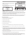
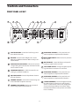
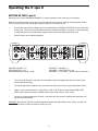
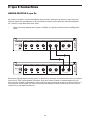
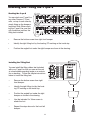
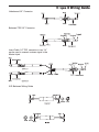
0
10
VOLUME
L
R
CH 3
CH 2
CH 1
CH 4
OL
OL
0
0
0
-6
SHAPE OUT
BALANCE
0
-6
VOLUME10
-12
SHAPE OUT
0
VOLUME10
SHAPE OUT
-18
-18
-24
-24
-24
CH 2
INJECT
-6
-12
-12
SHAPE OUT
-18
2 CH
CH 3
OL
0
10
CH 4
VOLUME
STEREO
0
10
VOLUME
4 CHANNEL
HEADPHONE AMP
4 CHANNEL HEADPHONE AMP
A
U
D
I
O
C Class Signal Processors
CH 1
MAIN
Safety Instructions
Caution: To reduce the hazard of electrical shock, do
not remove cover or back.
No user serviceable parts inside. Please refer all servicing to qualified personnel.
CAUTION
FOR CONTINUED PROTECTION AGAINST RISK
OF FIRE, REPLACE ONLY WITH SAME TYPE FUSE
ATTENTION
UTILISER UN FUSIBLE DE
RECHANGE DE MÊME TYPE
WARNING
DO NOT EXPOSE THIS EQUIPMENT
TO RAIN OR MOISTURE
AVIS
RISQUE DE CHOC ELECTRONIQUE
NE PAS OUVRIR
RISK OF ELECTRIC SHOCK
DO NOT OPEN
WARNING: To reduce the risk of fire or electric shock, do not expose this unit to rain or moisture.
The lightning flash with an arrowhead symbol within an equilateral triangle, is intended to alert the user
to the presence of uninsulated "dangerous voltage" within the products enclosure that may be of sufficient magnitude to constitute a risk of electric shock to persons.
The exclamation point within an equilateral triangle is intended to alert the user to the presence of important operating and maintenance (servicing) instructions in the literature accompanying the product..
Important Safety Instructions
1. Please read all instructions before operating the unit.
2. Keep these instructions for future reference.
3. Please heed all safety warnings.
4. Follow manufacturers instructions.
5. Do not use this unit near water or moisture.
6. Clean only with a damp cloth.
7. Do not block any of the ventilation openings. Install in accordance with the manufacturers instructions.
8. Do not install near any heat sources such as radiators, heat registers, stoves, or other apparatus (including
amplifiers) that produce heat.
9. Do not defeat the safety purpose of the polarized or grounding-type plug. A polarized plug has two blades with
one wider than the other. A grounding type plug has two blades and a third grounding prong. The wide blade or
third prong is provided for your safety. When the provided plug does not fit your outlet, consult an electrician for
replacement of the obsolete outlet.
10. Protect the power cord from being walked on and pinched particularly at plugs, convenience receptacles and at
the point at which they exit from the unit.
11. Unplug this unit during lightning storms or when unused for long periods of time.
12. Refer all servicing to qualified personnel. Servicing is required when the unit has been damaged in any way,
such as power supply cord or plug damage, or if liquid has been spilled or objects have fallen into the unit, the
unit has been exposed to rain or moisture, does not operate normally, or has been dropped.
Table of Contents
Introduction
2
C•que 8 Features
3
Controls and Connectors
Front Panel Layout
Rear Panel Layout
4
5
Operating the C•que 8
Setting Up the C•que 8
C•que 8 Master section
Stereo and Two Channel Modes
C•que 8 Channels
6-7
7
8
9
C•que 8 Connections
Linking Multiple C•que 8’s
Headphone Impedance and Sensitivity ratings
Cue Mix Set-up for Multitrack Vocal Recording
Cue Mix Set-up for Multitrack Rhythm section Recording
10
11
12
13
Stacking and Tilting the C•que 8
14
C•que 8 Wiring Guide
15
Specifications
16
Block Diagram
17
Copyright 2001, Samson Technologies Corp.
Printed June, 2002
Samson Technologies Corp.
575 Underhill Blvd.
P.O. Box 9031
Syosset, NY 11791-9031
Phone: 1-800-3-SAMSON (1-800-372-6766)
Fax: 516-364-3888
www.samsontech.com
1
Introduction
Congratulations on purchasing the Samson C•que 8 Headphone Amplifier! Although this unit
is designed for easy operation, we suggest you take some time out first to go through these
pages so you can fully understand how we’ve implemented a number of unique features. The
C•que 8 is a compact, high-quality device that allows you to monitor any stereo or monophonic
source signal (balanced or unbalanced) over as many as twelve separate headphones.
Providing unusually high power levels and superb audio fidelity, the C•que 8 is compatible with
virtually all popular headphone models. Front panel controls include a Master Input Level control and Stereo/2 Channel switch. Each headphone output has its own individual Shape Circuit
Level Meters, and Level control. Special output jacks on the rear panel allows any number of
C•que 8 units to be linked together with no loss of signal. The C•que 8 can be used in a wide
variety of applications, including recording studios, teaching labs, broadcast environments,
and for live performance. In this manual, you’ll find a more detailed description of the features
of the C•que 8, as well as a guided tour through the front and rear panels, step-by-step
instructions for using the C•que 8, a reference chart that gives impedance and sensitivity ratings for a number of popular headphone models, and full specifications. You’ll also find a warranty card enclosed—please don’t forget to fill it out and mail it so that you can receive online
technical support and so we can send you updated information about other Samson products
in the future.
With proper care and adequate air circulation, your C•que 8 will operate trouble free for many
years. We recommend you record your serial number in the space provided below for future
reference.
Serial number:
Date of purchase:
Should your unit ever require servicing, a Return Authorization number (RA) must be obtained
before shipping your unit to Samson. Without this number, the unit will not be accepted.
Please call Samson at 1-800-3SAMSON (1-800-372-6766) for a Return Authorization number
prior to shipping your unit. Please retain the original packing materials and if possible, return
the unit in the original carton and packing materials.
2
C•que 8 Features
MAIN
0
10
VOLUME
L
R
CH 1
CH 2
CH 1
CH 3
CH 4
OL
OL
0
0
0
-6
BALANCE
SHAPE OUT
0
VOLUME10
-12
-6
0
VOLUME10
-18
-24
-24
CH 2
-6
-12
SHAPE OUT
-18
-24
INJECT
SHAPE OUT
-12
SHAPE OUT
-18
2 CH
CH 3
OL
0
10
CH 4
VOLUME
STEREO
0
10
VOLUME
4 CHANNEL
HEADPHONE AMP
The Samson C•que 8 headphone amplifier utilizes the latest technology in gain management design. Here are
some of it’s features:
•
Four channel headphone mixer amplifier providing individual controls for each channel. Ideal for digitalaudio-workstations, stage and studios.
•
Dual headphone outputs; one rear, plus one front panel output per channel allowing a total of eight headphones connected at the same time.
•
Maximum output power on each channel regardless of different headphone impedances.
•
Left and Right Line inputs for master stereo bus on balanced TRS (Tip Ring Sleeve) 1/4” phone connectors.
•
Inject input on TRS (Tip Ring Sleeve) unbalanced stereo phone connector allowing for the insertion of an
additional stereo signal that is mixed with the stereo Line input for "more me" mixing.
•
2-Channel/Stereo mode switch configures the C que 8 to operate in traditional stereo mode, or in 2Channel, mono mode.
•
Balance controls pan in Stereo mode, or the level balance between the Line and Inject inputs in 2Channel mode.
•
EQ Shape circuit on each channel provides a “music contour” equalization curve that boosts the low and
high frequencies of the headphone output.
•
Each channel has a six-segment, LED Output meter, with a range of –24 to clip, making it easy to monitor
the channel output level.
•
A six-segment Main Level meter provides a clear and accurate indication of Line input level with an operating range of –24 to clip.
•
Stacking Rubber Bumpers are included allowing several C que 8’s, or other Samson C Class units, to be
stacked on top of each other creating a neat array of high quality signal processors.
•
Tilting Feet are also included so that the C class units can be positioned in a comfortable and ergonomic
position on desktops and workstations.
•
19”, 1 u (one rack space) rack-mount kit available.
•
Three year extended warranty.
3
Controls and Connectors
FRONT PANEL LAYOUT
2
1
3
5
4
CH 1
MAIN
6
CH 2
CH 1
L
R -6
BALANCE
SHAPE OUT
0
VOLUME
10
11
0VOLUME 10
SHAPE OUT
-18
-24
-24
CH 2
-18
-24
0 VOLUME 10
CH 4
STEREO
12
-6
-12
-12
-18
INJECT
CH 4
0
SHAPE OUT
SHAPE OUT
10
CH 3
9
OL
-6
-12
2 CH
CH 3
0
0
10
VOLUME
8
OL
OL
0
7
0
10
VOLUME
4 CHANNEL
HEADPHONE AMP
14
13
1
MASTER VOLUME - Controls the level being sent to
the individual channels.
8 HEADPHONE CHANNEL 3 - The same knob and
switch compliment is duplicated for Channel 3.
2
BALANCE- Controls Left and Right Pan in Stereo
Mode or Level Balance between Main and Inject in 2
Channel Mode.
9 MAIN POWER SWITCH - When turned on, activates
the C•que 8.
3
4
5
6
7
MAIN MASTER LEVEL METER - Indicates the amount
of signal being driven into the four channels from the
master volume control.
HEADPHONE OUTPUT - 1/4 TRS Connector for connecting any standard headphone.
10 MASTER INJECT - Stereo TRS front panel input for
injecting a signal into the main mix.
11 2CH/STEREO SWITCH - Changes the global operating mode from normal stereo to 2-channel.
12 HEADPHONE CHANNEL 2 - The same knob and
switch compliment is duplicated for Channel 2.
EQ SHAPE SWITCH - Provides Equalization Contour
for music listening.
13 HEADPHONE CHANNEL 4 - The same knob and
switch compliment is duplicated for Channel 4.
CHANNEL VOLUME - Controls the volume being sent
to the individual headphone channels.
CHANNEL LEVEL METER - Displays the amount of
power being supplied to the channels.
4
14 STACKING BUMPERS - Sleek and highly functional,
the rubber bumpers allow you to stack several C•
que 8’s or other Samson C class units. Angled feet
are also included, providing a convenient tilting
mechanism that allows easy operation on workstations or desktops.
Controls and Connectors
REAR PANEL LAYOUT
A
C
B
SAMSON
D
CH 4
F
E
CH 3
CH
CH 2
2
G
CH 1
LINK OUTPUT
LINE INPUT
POWER
AC IN
18 V
+
-
LEFT
500mA
RIGHT
BALANCED
LEFT
RIGHT
BALANCED
MADE IN CHINA
A
AC INLET - AC power supply connector is here.
E
CHANNEL 1 OUTPUT - Rear panel headphone output for
Channel 1.
B
CHANNEL 4 OUTPUT - Rear panel headphone output for Channel 4.
F
LINK OUTPUTS - Outputs that are tied to the main input
for linking to another headphone amp or other device.
CHANNEL 3 OUTPUT - Rear panel headphone output for Channel 3.
G
LINE INPUT - The main signal input to the headphone
amp. Plugging into the left jack only sends the signal to
both the left and right.
C
D
CHANNEL 2 OUTPUT - Rear panel headphone output for Channel 2.
5
Operating the C•que 8
SETTING UP THE C•que 8
Setting up your C•que 8 Headphone Amplifier is a simple procedure, which takes only a few minutes.
Remove all packing materials (save them in case of need for future service) and plug the provided AC adapter
cord in the rear AC inlet, but don’t plug the power cable into a wall outlet just yet.
•
Connect the output from the device you want monitored to the Left/Right LINE INPUT jacks on the C•que
8 rear panel. The C•que 8 accepts both balanced and unbalanced signals. Generally, a balanced signal
is preferable because it provides better signal-to-noise ratio and reduced extraneous noise.
•
Set the controls to the following positions:
MAIN
CH 1
10
VOLUME
L
R
-6
BALANCE
0
VOLUME10
SHAPE OUT
VOLUME10
-6
-12
SHAPE OUT
-18
-24
-24
0
10
-18
-24
CH 4
VOLUME
STEREO
MASTER VOLUME – Off
ST/2CH SWITCH – Out
MASTER BALANCE- Center, 12:00
0
-12
-18
CH 2
CH 4
OL
0
-6
SHAPE OUT
2 CH
CH 3
0
SHAPE OUT
-12
INJECT
CH 3
OL
0
0
CH 2
CH 1
OL
0
10
VOLUME
4 CHANNEL
HEADPHONE AMP
CHANNEL 1 VOLUME – 0
CHANNEL 1 SHAPE SWITCH- Out
CHANNEL 2 - 4’s Controls - Set the Same as Channel 1
•
Turn the master Volume knob and all four headphone Channel Output knobs to their minimum (fully
counterclockwise) setting.
•
Plug the C•que 8 power adapter into a wall outlet and switch the unit on by pressing the power switch.
•
Apply a signal, like the output of a mixer playing a CD, to the C•que 8’s rear-panel Left/Right LINE
INPUT jacks. Raise the master VOLUME until the main meter reaches -18 to -12 dB.
•
Connect a set of headphones to Channel 1 and slowly turn the channel’s Volume knob clockwise until
you hear the desired level.
WARNING: Because the C•que 8 is capable of generating extremely high volume levels, always start with the
channel Volume knob at minimum and then slowly turn it up.
6
Operating the C•que 8
SETTING UP THE C•que 8 - Continued
•
Repeat the previous step for all Channels that have headphones connected, making sure to start the
VOLUME knob completely counterclockwise and then slowly raising it until the desired level is achieved.
If you have connected different models of headphones to the various Channel Headphone jacks, you
may find that some require more gain than others to achieve the same volume. This kind of disparity will
occur if the various headphones have different impedances. The lower the impedance, the louder the
headphone will sound compared to another, higher impedance headphone at the same VOLUME setting.
Another factor affecting headphone loudness is called sensitivity. This is generally measured by determining the decibel (dB) level generated by 1 mW of power input. The higher the dB rating, the louder the
headphone. See the Reference chart on page 13 of this manual for more details.
•
To achieve optimum signal-to-noise ratio, the master VOLUME should generally be set as high as possible, short of audible distortion. However, if this results in your getting blasted with signal even though the
channel volume is near minimum, you’ll need to decrease the Master Volume while raising one or more
channel volume levels. Conversely, if you find that you have to raise one or more headphone Channel
Volume knobs to maximum or near maximum to achieve the desired level, try increasing the master
Volume level while decreasing the channel volume(s).
C•que 8 Master Section
1 Master Volume
The C•que 8’s master VOLUME control is used to adjust the input signal connected to the main Left and Right
inputs. In addition, the master VOLUME control adjusts the level of the signal inserted in the INJECT, which is
summed with the MAIN Left and Right input signal.
2 Balance Control
1
The C•que 8’s main channel has a BALANCE control,
which controls how much signal is sent to the left or right
headphone outputs. The control knob has a center detent
which indicates that the left and right sides are balanced.
In 2 Channel mode, the signal becomes mono and the
BALANCE knob adjusts the level balance between the
signals connected to the LEFT inputs and signals connected to the RIGHT inputs. (For more information on 2Channel mode, see the section “Mixing Signals in 2
Channel Mode” found on page 9 of this manual.)
2
3
MAIN
OL
0
0
10
L
VOLUME
R
-6
BALANCE
SH
-12
SH
-18
-24
4
INJECT
5
2 CH
STEREO
3 Master Level meter
The C•que 8’s master section includes a 6 segment LED LEVEL meter which monitors the input level from the
MAIN Left and Right Inputs in Decibels (dBs) from –24 to OL (overload). If the LEVEL meter displays an OL signal, then turn down the signal using the master VOLUME control.
4 Master Inject
The C•que 8’s MASTER INJECT is a TRS input (Tip, Ring, Sleeve), that allows a second stereo signal to be
inserted and summed together with the MAIN Left and Right signals. You can use a stereo signal from your mixers bus outputs or auxiliary sends to balance the mix between two stereo signals like rhythm tracks and vocals.
5 2 Channel/Stereo switch
The 2 CH/STEREO switch is used to change between the C•que 8’s two global operating modes, 2-Channel and
Stereo. In Stereo mode the left and right Line inputs are mixed with the left and right Inject inputs, in stereo, with
the Balance knob controlling the left and right panning. In 2-Channel mode, the left and right LINE inputs are
mixed with the left and right INJECT inputs into a single mono signal with the BALANCE knob controlling the level
difference between the LEFT and RIGHT inputs.
7
Operating the C•que 8
C•que 8 CHANNELS
6 Headphone Output
The C•que 8’s Headphone Output jack accepts a standard 1/4” TRS connector for easy interface with
most professional headphones. Once the master VOLUME has been set, the channels output level
is set by the VOLUME knob.
7 EQ Shape
6
7
9
8
CH 1
Each of the four C•que 8 channels features an EQ
SHAPE switch allowing individual equalization contour for each channel. When the EQ SHAPE switch is
in, the LED will illuminate indicating the EQ SHAPE
circuit is engaged. The EQ SHAPE circuit provides a
pre-set equalization curve designed to sound good on
most program music. In this mode, the low frequencies have a 6dB boost at 100Hz and the high frequency are boosted 6dB at 12kHz. When the EQ SHAPE
switch is in the out position, frequency response of
the channel is flat.
CH 2
CH 1
OL
0
SHAPE OUT
0
VOLUME
10
-6
-12
SHAPE OUT
-18
-24
CH 2
0
10
VOLUME
8 VOLUME Control
The channel VOLUME control is used to adjust the channel headphone output. The volume control
will adjust the level of the front panel headphone outputs, as well as that channel’s rear panel headphone outputs.
9 CHANNEL LEVEL Meter
Each C•que 8 Channel has an 6 segment, LEDlevel meter which monitors the output of the channel in
Decibels (dBs) –24 toOL (overload). If the LEVEL meter displays an OL signal, then turn down the
channel VOLUME, and if necessary, also turn down the master VOLUME .
8
Operating the C•que 8
STEREO AND TWO-CHANNEL MODES
All of the C•que 8’s four channels can be set to operate in two different modes: Stereo and 2 Channel.
Stereo Mode
Stereo mode is a normal operating mode where all mix inputs from MAIN and INJECT, maintain their stereo
image throughout the signal path to each headphone output. The BALANCE control is used to adjust the stereo
image between the Left and Right side. To design a monitor mix in the Stereo mode, follow these steps:
•
Press the ST/2CH switch to the OUT position. You’ll notice the switch LED is not illuminated indicating
that the main input is in STEREO mode.
•
Make a Stereo connection from your mixer’s auxiliary or bus outputs to the main Left and Right Line
inputs on the C•que 8’s rear panel.
•
In the Stereo mode, the BALANCE control adjusts the loudness between the left and right headphone
outputs.
Mixing Signals in 2-Channel Mode
In 2-Channel mode, the MAIN left and right inputs and the INJECT left and right inputs are summed to a common
mono signal that is present on all of the C que 8’s headphone outputs. The BALANCE control is now used to
adjust the volume difference between the left and the right inputs. In a recording situation, you can use the 2Channel mode to make a “More Me” cue mix, letting you adjust the volume of the mix directly on the C que 8. To
design a monitor mix in the 2-Channel mode, follow these steps:
•
Press the ST/2CH switch to the IN position. You’ll notice the
switch LED is now illuminated indicating that the C•que 8 is
in 2-Channel mode.
•
Create a mono monitor mix on one of your mixer’s auxiliary
sends and make a connection from that aux send output to
the MAIN Left input on the C•que 8’s rear panel.
MAIN
OL
0
0
10
VOLUME
L
R
-6
BALANCE
-12
•
Use your mixer’s direct output, or another aux send, to route
the signal of the lead vocal channel and make a connection
from that output to the C•que 8’s MAIN Right input.
-18
-24
INJECT
2 CH
•
Now, you can use the BALANCE control to adjust the level
difference between the monitor mix and the vocal channel.
By using a combination of the MAIN VOLUME and BALANCE controls you can dial up the perfect mix directly on the
C que 8.
9
STEREO
C•que 8 Connections
LINKING MULTIPLE C•que 8’s
Any number of C•que 8’s can be linked together (daisy-chained), allowing you to monitor an input signal over
more than twelve sets of headphones, or to give individual musicians more control over their own headphone
mix. To do this, simply follow these basic steps:
•
Make a connection between one C•que 8’s Left/Right Link outputs and the next one’s Left/Right Main
inputs.
SAMSON
CH
CH 4
4
CH
CH 3
3
CH
CH 2
2
CH
CH 1
1
LINE INPUT
LINK OUTPUT
POWER
AC IN
18 V
+
-
LEFT
500mA
RIGHT
LEFT
BALANCED
RIGHT
BALANCED
MADE IN CHINA
SIGNAL FLOW
SIGNAL FLOW
SAMSON
CH
CH 4
4
CH
CH 3
3
CH
CH 2
2
CH
CH 1
1
LINK OUTPUT
LINE INPUT
POWER
AC IN
18 V
+
-
LEFT
500mA
RIGHT
BALANCED
LEFT
RIGHT
BALANCED
MADE IN CHINA
Because the C•que 8 Stereo Link output jacks are electronically balanced, we recommend the use of 3-conductor
cable and 1/4" TRS (Tip/Ring/Sleeve) connectors. Even when several C•que 8’s are linked together this way,
there is no loss of power or audio fidelity—every Channel on every C•que 8 will sound just as loud and clear as if
it were the only unit connected. The status of the front-panel Stereo/2 CH buttons affects only that unit and has
no effect on any subsequent linked units.
10
C•que 8 Connections
HEADPHONE IMPEDANCE AND SENSITIVITY RATINGS
Virtually all headphones that terminate in a stereo 1/4" plug can be used with the C•que 8 Headphone Amplifier.
This chart provides a partial listing of some of the more popular models, along with their impedance and sensitivity ratings. As described on page 7 of this manual, headphones with lower impedances (or higher sensitivity) will
sound louder as compared to other, higher impedance (or lower sensitivity) headphones at the same channel
Volume setting. Samson Technologies has no connection with any of these manufacturers, nor do we endorse
any particular models for use with the C•que 8. This is simply a reference listing for your convenience. For more
information about any of these headphones, contact the manufacturer directly.
SAMSON HEADPHONES
Model
Impedance
Sensitivity /mW
PH60
RH100
RH300
RH600
CH70
CH700
100 dB
106 dB
106 dB
106 dB
103 dB
108 dB
32 ohm
64 ohm
32 ohm
40 ohm
32 ohm
64 ohm
OTHER MANUFACTURER'S HEADPHONES
Manufacturer
Model
Impedance
AKG
K-141
600 ohm
AKG
K-240
600 ohm
Beyer
DT-150
250 ohm
Beyer
DT-801
250 ohm
Fostex
T-10
50 ohm
Fostex
T-20
50 ohm
Fostex
T-40
50 ohm
Sennheiser
HD-450 (original) 70 ohm
Sennheiser
HD-450 Series II
60 ohm
Sony
MDR-7502
45 ohm
Sony
MDR-7504
45 ohm
Sony
MDR-7506
63 ohm
11
Sensitivity /mW
98 dB
88 dB
114 dB
114 dB
91 dB
96 dB
98 dB
94 dB
94 dB
100 dB
103 dB
106 dB
0
INJECT
VOLUME
12
0
STEREO
-24
-18
-12
-6
SA
M
SO
N
21
R
LEAD VOCAL
FROM CONSOLE
DIRECT OUT OR AUX SEND
SIGNAL FLOW
SIGNAL FLOW
SIGNAL FLOW
RHYTHM SECTION MIX
FROM CONSOLE AUX 1 & 2
CH 2
SHAPE OUT
SHAPE OUT
CH 1
0
0 VOLUME10
0 VOLUME10
-24
CH 4
-18
-12
-24
SHAPE OUT
-18
-12
-6
0
-6
SHAPE OUT
CH 3
0
CH 3
OL
CH 2
OL
Backing Vocals
10
VOLUME
0 VOLUME 10
CH 1
CH 4
4 CHANNEL
HEADPHONE AMP
The following example shows a headphone mix for a vocal overdub session. The backing music and vocals are sent via the mixers
auxiliary sends to the C que 8’s MAIN input. The lead vocal channel is connected from the console’s direct output to the C que 8’s master INJECT input. The C cue 8 is set to 2-channel mode, so that the BALANCE controls the level difference between the backing track
and lead vocal. This allows the lead vocalist to control the balance between his track and the backing tracks for a “more me” mix.
Lead Vocal
2 CH
R
OL
MAIN
RIGHT
LINE INPUT
LEFT
BALANCE
10 L
TO LEFT AND RIGHT
LINE INPUT ON
REAR PANEL
C•que 8 Connections
CUE MIX SET-UP FOR MULTITRACK VOCAL RECORDING
RIGHT
RIGHT
13
RIGHT
SIGNAL FLOW
RIGHT
BALANCED
RIGHT
BALANCED
LEFT
INJECT
0
10
VOLUME
INJECT
0
10
VOLUME
INJECT
0
10
VOLUME
INJECT
0
10
VOLUME
2 CH
0 VOLUME10
10
VOLUME
0
10
VOLUME
10
10
VOLUME
10
VOLUME
CH 3
10
VOLUME
-12
0
10
VOLUME
10
VOLUME
CH 1
0
10
VOLUME
CH 3
0
0
10
10
VOLUME
0
10
VOLUME
CH 2
0
10
VOLUME
SIGNAL FLOW
CH 4
-24
STEREO
-24
10
10
VOLUME
-6
-12
-24
SHAPE OUT
SHAPE OUT
-18
0
0
-6
-12
-18
SHAPE OUT
-18
-12
SHAPE OUT
0
-6
OL
CH 3
0
CH 2
OL
0
CH 1
OL
MAIN
SIGNAL FLOW
CH 4
-24
CH 2
-24
10
VOLUME
-6
-12
-24
SHAPE OUT
SHAPE OUT
-18
0
-6
-12
-18
SHAPE OUT
SHAPE OUT
-18
-12
-6
0
CH 3
OL
CH 3
0
CH 2
OL
0
CH 1
SIGNAL FLOW
0
0
OL
CH 1
CH 2
CH 4
SHAPE OUT
CH 4
CH 4
CH 4
CH 4
-24
10
10
VOLUME
-18
0
0
-18
-24
-12
-6
-24
SHAPE OUT
SHAPE OUT
SHAPE OUT
0
-18
-12
-6
0
-6
OL
0
0
CH 3
0
CH 2
OL
CH 1
0
CH 1
SIGNAL FLOW
OL
MAIN
CH 2
CH 4
-6
-12
-24
SHAPE OUT
SHAPE OUT
-18
0
-6
-12
-18
MAIN
STEREO
L
R
BALANCE
2 CH
0 VOLUME10
-24
SHAPE OUT
SHAPE OUT
-24
STEREO
L
R
BALANCE
2 CH
-6
-18
-12
STEREO
L
R
BALANCE
2 CH
L
R
BALANCE
0
CH 3
OL
CH 3
0
CH 2
OL
CH 1
0
CH 1
OL
MAIN
4 CHANNEL
HEADPHONE AMP
4 CHANNEL
HEADPHONE AMP
4 CHANNEL
HEADPHONE AMP
4 CHANNEL
HEADPHONE AMP
Keyboards From Mixer Direct Out
From Mixer Direct Out
Bass Guitar
From Mixer Direct Out
Lead Guitar
Rhythm Guitar
From Mixer Direct Out
The following example shows a sophisticated cue mix for tracking a rhythm section during a recording session using five C•que 8’s. The complete mix for all the
musicians is sent via the console’s auxiliary send to the C•que 8’s RIGHT LINE input and daisy-chained from unit to unit. Then signal from each instrument is connected from the console’s direct outputs to each of C•que 8’s master INJECT inputs using a mono 1/4-inch (TIP/SLEEVE) cable. (By using a mono 1/4-inch cable only
the Left Inject input is connected). The C•cue 8’s are set to 2-channel mode, so that the BALANCE controls the level difference between the backing tracks and individual instruments. This allows the lead vocalist or musician to dial up his or her own track for a “more me” mix.
RHYTHM SECTION AND BACKING TRACKS MIX
FROM CONSOLE AUX SEND
LEFT
LINE INPUT
RIGHT
LINK OUTPUT
LEFT
LINE INPUT
BALANCED
LEFT
LINE INPUT
BALANCED
RIGHT
RIGHT
BALANCED
LEFT
LINE INPUT
BALANCED
LEFT
LINK OUTPUT
BALANCED
LEFT
LINK OUTPUT
BALANCED
LEFT
LINK OUTPUT
TO RIGHT
LINE INPUT ON
REAR PANEL
C•que 8 Connections
CUE MIX SET-UP FOR MULTITRACK RHYTHM SECTION RECORDING
Stacking and Tilting the C que 8
Stacking the C que 8
CH 1
MAIN
You can stack one C cue 8, or
any other Samson C Class
units, on top of each other by
simply lining up the bumpers.
Important Note: When stacking the C que 8, be sure that
only the bottom unit has the
tilting feet installed.
0
10
VOLUME
R
L
BALANCE
CH 3
CH 2
CH 1
OL
0
0
-6
SHAPE OUT
0
10
VOLUME
-6
SHAPE OUT
-18
-24
-24
-24
CH 2
0
10
VOLUME
CH 4
0
10
VOLUME
4 CHANNEL
HEADPHONE AMP
STEREO
CH 1
MAIN
L
R
BALANCE
CH 3
CH 2
CH 1
CH 3
CH 4
OL
OL
OL
0
0
0
-6
SHAPE OUT
0
10
VOLUME
-12
-6
SHAPE OUT
0 VOLUME10
SHAPE OUT
-18
-18
-24
-24
-24
CH 2
INJECT
-6
-12
-12
SHAPE OUT
-18
2 CH
-6
-12
SHAPE OUT
-18
INJECT
10
VOLUME
0 VOLUME10
-12
SHAPE OUT
-18
0
CH 4
OL
0
-12
2 CH
CH 3
OL
0
10
VOLUME
CH 4
0
10
VOLUME
STEREO
•
Remove the bottom screw from right front bumper.
•
Identify the right tilting foot by the locating “R” marking on the inside top.
•
Position the angled foot under the right bumper as shown in the drawing.
4 CHANNEL
HEADPHONE AMP
Installing the Tilting Feet
CH 3
R
NCE
You can install the tilting rubber feet included
with your C que 8 so that you can set the unit
at a comfortable operating angle on a workstation or desktop. Follow the simple instructions
below to install the tilting feet.
0
0
0
10
0
•
Remove the bottom screw from right
front bumper.
•
Identify the right tilting foot by the locating “R” marking on the inside top.
•
Position the angled foot under the right
bumper as shown in the drawing.
•
Use the included 3 x 16mm screw to
attach the foot.
•
Repeat the steps above for the front left
bumper.
14
VOLUME
10
-6
-12
T
-18
-24
0
10
CH 4
OL
VOLUME
10
4 CHANNEL
HEADPHONE AMP
C•que 8 Wiring Guide
Unbalanced 1/4” Connector
Balanced TRS 1/4” Connector
Insert Cable 1/4” TRS connector to two 1/4”
can be used to connect a stereo signal to the
Master Inject.
XLR Balanced Wiring Guide
15
Specifications
Master Section (Rear Panel)
Input
Impedance
Max. input level
CMRR:
2 TRS Balanced 1/4" (Left-Right) or (Left mono)
15 k Ohms balanced
+26 dBu balanced
Min 40dB, >55 dB @ 1 kHz
Master Section (Front Panel)
Master Volume control
Master Level Meters
Master Inject
Controls
0 - 10
6 Segment LED (–24 to OL)
1/4" TRS jack (Left-Right)
ST/2CH Switch, Volume Control,Balance Control
Link Output
Connectors
Max Output Level
2-1/4" TRS Balanced (Left-Right) Parallel to Main Input
Matches Main Input
Channels
Impedance
Max. input level
Level Meters
Outputs
Max. output level
Impedance minimum
Controls
10 k Ohms unbalanced
+21 dBu unbalanced
6 Segment LED (–24 to OL) (load compensating)
2 - 1/4" TRS (Left-Right) Headphone outputs per Channel
140 mW at 32 ohms, 385mW at 66 ohms.
8 Ohms
EQ Shape Switch, Volume Control
Global Specifications
Frequency response
Noise
THD
10 Hz to 32 kHz, +0/- 3 dB
> 90 dB, unweighted, 22 Hz to 22 kHz
0.008 % typ. @ +4 dBu, 1 kHz
Power Supply
Mains Voltages USA/Canada
Mains Voltages Europe
Power Inlet
Power Consumption
105-125 VAC ~, 60 Hz
215 – 254 VAC~,50Hz
Standard IEC receptacle / with fuse
29 Watts Max.
Physical
Dimensions
Net Weight
Shipping Weight
1 3/4" (44.5 mm) * 19" (482.6 mm) * 8 1/2" (217 mm)
5.5lbs., (2.5 kg)
8lbs., (3.6 kg)
16
C•que 8 Block Diagram
17
Samson Technologies Corp.
575 Underhill Blvd.
P.O. Box 9031
Syosset, NY 11791-9031
Phone: 1-800-3-SAMSON (1-800-372-6766)
Fax: 516-364-3888
www.samsontech.com