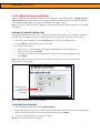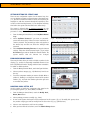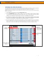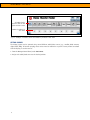
1
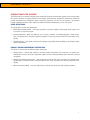
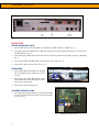
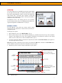
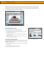
PRODUCT MANUAL
Intuition HT
Home Theater Switching Application
800.426.6844 | 503.648.6500 | 503.648.7500 f
1050 NW 229th Avenue | Hillsboro OR 97124
www.mti-interactive.com
MTI P/N 063-0209-00 | Rev B | July 2004
Product Manual – INTUITION HT
INTRODUCTION/SYSTEM OVERVIEW
The Intuition HT is an interactive display system designed to showcase home theater systems and accessories. With
this system, customers can easily configure a home theater system and then compare the performance of different
product combinations by substituting system components. Customers can also use the system to get detailed
product information and thus make comparisons between different manufacturers, prices, and options.
USAGE APPLICATIONS
The system offers several retail applications:
•
Retail Product Demonstration – The system provides an attractive display to demonstrate audio systems and
accessories to prospective buyers.
•
Customer Attraction - When the display is not in use by a customer, it automatically plays a video “attract
loop.” The attract loop is designed to grab the attention of a passing customer and thus increase traffic to the
display.
•
Employee Training – The system can help train employees by providing them the ability to test different audio
system combinations.
PRODUCT DESCRIPTIONS/GENERAL SPECIFICATIONS
The system is comprised of the following major components:
•
Display fixture – cabinet that showcases the home theater components and accessories. It contains the
hardware that connects the audio components together and the switching modules that activate the selected
components.
•
Intuition Touch Panel (touchscreen) – flat panel monitor that provides the user interface for controlling the
display. When a customer touches a selection button on the screen, it activates the selected component in the
display.
•
Master Control Unit (MCU) – processor that links and controls the touchscreen and switching hardware.
3
Product Manual – INTUITION HT
fig. 1 – Master Control Unit
INSTALLATION
MASTER CONTROL UNIT (MCU)
1.
Insert a USB cable into the top USB slot in middle rear of MCU (indicated as USB in fig. 1).
2.
Insert blue, male-ended VGA monitor cable from the touchscreen into female monitor port on the left rear of
the MCU (Monitor, fig. 1).
3.
Insert white/grey female-ended serial cable from the switching system into left male serial port (Switching,
fig. 1).
4.
Insert red and white male RCA cables into same color ports (Audio, fig. 1).
5.
Insert power cable into power port (AC, fig. 1).
TOUCHSCREEN
1.
Insert a USB cable from the MCU into the USB
slot on the bottom of the touchscreen (circled
in fig. 2).
2.
Insert blue, male-ended VGA monitor cable
from the MCU into female monitor port on the
bottom of the touchscreen.
3.
fig. 2 – Touchscreen
Insert power cable into power port.
SWITCHING INTERFACE BOARD
1.
Insert white/grey female-ended serial cable from the MCU
into the interface board connected to your MTI switching
system. (fig. 3)
fig. 3 – Switching interface board
4
Product Manual – INTUITION HT
OPERATION
To use the display, turn on the MCU by pressing the power button
on the right side of the box. The system will perform a system
boot, lasting approximately 2 minutes, and then start playing the
video “attract loop.” The attract loop continues to play until
someone touches the Start Here button, switching the system to
a Welcome screen (main menu).
The Welcome screen is the starting point for the customer’s
session and also provides access to the Manager Control Panel (see
“System Configuration and Maintenance” on page 7).
BUILDING A SYSTEM
The main Welcome screen offers two choices: build a system
choosing your own components or choose from one of three preconfigured systems.
fig. 4 – Welcome screen
To build you own system:
1.
On the Welcome screen, select Build My Own. (fig. 4)
2.
On the system selector screen, select a product category (e.g., A/V Receivers) from the top. A list of numbers
appears in the middle of the screen. These numbers correspond to the component’s position on the display
fixture. Use the scroll arrows to view all available models. (fig. 5)
3.
Touch the component number to activate the component and add it to Your Home Theater (room graphic in
the lower right corner of screen).
Note: When you add a component to your system, the component’s Add button switches to a Clear Item button.
Use this button if you want to remove the component from your system.
4.
Repeat this process to add or change components to your system.
returns to welcome screen
return to attract loop
shows three pre-configured
product
categories
scroll
arrow
scroll arrow
basic
instructions
components you have
added to your system (touch
for larger image)
not
available
basic operating
accesses different a/v
sources to audition your system
mute
fig. 5 – System selector
5
Product Manual – INTUITION HT
Note: You can view a larger image of your system by touching the room icon. This opens a new screen showing all
components currently in your system. (fig. 6) To remove or change a component, touch the component you want
to change. This returns you to the component selection screen. You can now either press the component’s button
to remove it from your system, or select a new component.
fig. 6 – Your System screen
USING PRE-CONFIGURED SYSTEMS
To build a system using a recommended configuration:
1.
On the Welcome screen, select Pre-configured systems.
2.
On the Pre-configured systems screen, select one of the systems –
Good, Better, or Best. (fig. 7)
3.
The system selector screen appears. All components for this system are
added to your system.
4.
You can now modify this system using the steps outlined in the
“Building a System” section above.
SELECTING AN AUDIO/VIDEO SOURCE
Once you have built your home theater system, you can audition the system
using different audio/video sources (e.g., satellite, DVD, antenna, digital
cable, PVR). To use this feature:
1. Touch the Sources button. This opens a new window listing all available
video sources.
2. Select the audio/video source you want to use.
3. Press the X in the upper right corner to close.
6
fig. 7 – Pre-configured systems
Product Manual – INTUITION HT
SYSTEM CONFIGURATION AND MAINTENANCE
System configuration and maintenance functions can be performed in two different modes – Manager Mode and
Super User Mode. These modes, which are accessed using different passwords, provide access to different functions
on the Manager Control Panel (see “Accessing the Manager Control Panel” below).
Note: Access to the Super User Mode should be restricted to avoid making undesired changes to the system
configuration.
ACCESSING THE MANAGER CONTROL PANEL
The Manager Control Panel is used to access configuration and maintenance functions (fig. 8). Options available on
this panel depend on whether you log into the Manage Mode or the Super User mode. To access this panel:
1.
If the attract loop is playing, touch the Start Here button to move to the Welcome screen.
2.
Touch the MTI logo (upper left-hand corner) three times.
3.
A password prompt appears.
>
To operate the system in Manager Mode, enter the Manager Mode password (default from
factory is 9751); then press Submit.
>
To operate the system in Super User Mode, enter the Super User password (369258147); then
press Submit.
Note: You are given three tries to enter the correct password. If you are unsuccessful, you must exit
and re-enter this section again.
Configure Chains
option only
available in Super
User Mode
fig. 8 – Manager Control Panel – Super User Mode
SETTING/RESETTING PASSWORDS
1.
From the Manager Control Panel, touch Set/Reset Password.
2.
On the Set/Reset Password screen, enter the current password and the new password in the appropriate fields.
Enter the new password again in the confirm password field; then press Submit.
3.
The system notifies you that the password has changed.
Note: Keep a careful record of the password.
7
Product Manual – INTUITION HT
SETTING/RESETTING THE ATTRACT LOOP
There are two configuration options for the attract loop. You
can set whether you want to password-protect the attract loop
(i.e., password is needed to initiate a session, thus requiring an
employee to walk the customer through the experience). You
can also set the inactivity timeout (i.e., the length of inactivity
time before the system switches back to the attract loop).
The system is shipped with no password protection on the
attract loop and the inactivity timeout is set for 3 minutes. If
you want to change these settings:
1.
From the Manager Control Panel, touch Set/Reset Attract
Loop.
2.
Select Set/Reset Password if you want to passwordprotect the attract loop. Follow on-screen instructions to
create a password. The password you select only applies to
the attract loop and does not affect the manager mode
password.
3.
Select Set/Reset Inactivity Timeout to change the timeout
settings. Select the desired timeout length. (fig. 9) Select
No Timeout if you want to disable the timeout feature. The
system notifies that the timeout has changed.
fig. 9 – Inactivity Timeout screen
ENABLING/DISABLING PRODUCTS
There may be times when you need to disable a product in the
display (e.g., product is temporarily unavailable because it has
been sold/removed from the display) and then later re-enable it.
To enable or disable products:
1.
From the Manager Control Panel, touch Configure Positions.
2.
Select a product category (e.g., A/V Receivers) from list on
the top.
3.
Touch the component number you want to disable. When a
product is disabled, a red X appears instead of the product
number. (fig. 10) Touch the number again when you want
to re-enable the product.
fig. 10 – enable/disable product
MODIFYING GOOD, BETTER, BEST
Use this option to modify the components that comprise the
pre-configured systems (i.e., Good, Better, and Best).
fig. 11 – Modify Good, Better, Best screen
1.
From the Manager Control Panel, touch the Modify Good,
Better, Best button.
2.
Select package you want to modify (e.g., Best).
3.
A new screen appears showing the current components for this system. (fig. 11) To modify this system, select
the product category you want to modify from the list on the top (e.g., A/V Receivers).
4.
Select a new component to add it to the package.
5.
After you have made all selections, touch the Submit Change button.
8
Product Manual – INTUITION HT
CONFIGURING CHAINS (SUPER USER MODE ONLY)
This feature allows you to configure and test the system so that the display’s user interface (component categories
and products that the customer sees on the display screen) matches the products in the display.
Note: This option is only available if you have logged into the Super User mode (see “Accessing the Manager Control
Panel” section above).
1.
From the Manager Control Panel, touch the Configure Chains button.
2.
Press the Enable/Disable button to enable or disable a chain. If you enable a chain, the product category
(e.g., A/V Receiver) will be shown on the system selector screen. (fig. 12) If you disable a chain, the product
category is not included on the system selector screen and is not available to the customer.
3.
Use the +1 +5 -1 -5 buttons to set the number of products in each category. For example, if there are eight
A/V receivers in the display, set the # of positions to 8. When a customer selects A/V Receivers on the system
selector screen, they will now see eight products (represented by numbers 1 – 8). (fig. 13)
4.
Press the Test Chain button if you want to test all positions in a chain. For example, if you press the Test Chain
button for A/V Receivers, the system will cycle through all A/V receiver positions (in numerical order) turning
each receiver on and off. This feature helps confirm that the display is wired and configured correctly.
number of
products in
the display
Disable will
remove category
from the system
selector screen
Tests all product
positions in the
chain
used to change
the number of
products
fig. 12 – Configure Chains screen
9
Product Manual – INTUITION HT
all enable chains
appear as tabs on the
system selector screen
number of products in
the chain
fig. 13– Example of enabled chains and number of products in the chain
SETTING SOURCES
The display system can be operated using several different audio/video sources (e.g., satellite, DVD, antenna,
digital cable, PVR). To function properly, these sources must be matched to a specific source position associated
with the display. To set the sources:
1. From the Manager Control Panel, touch Set Sources.
2. Assign each audio/visual source to the desired position.
10
Product Manual – INTUITION HT
TROUBLESHOOTING
Symptom
Problem
Solution
Error message
appears on
the
touchscreen
during startup
System error
On the touchscreen, touch the Reboot System button. If this
button is not available, turn the MCU power button off and then
back on.
No image on
the
touchscreen
Power strip is not plugged in
or the switch is turned off
Verify all power connections and verify that the switch on the
power strip is turned on.
MCU is turned off
Turn on the MCU.
Touchscreen
does not
display User
Interface after
completion of
the boot
sequence
VGA cable may not be
Refer to the Installation Guide and verify that the VGA cable is
correctly connected or may be attached to the MCU and that it is not damaged.
damaged.
Touchscreen
does not
respond to
user
USB cable may be damaged or
attached incorrectly
Ensure that the USB cable is connected to the MCU and
touchscreen.
Touchscreen may be damaged
Check for damage to the touchscreen housing or cabling
connections.
Touchscreen may be dirty
Check touchscreen manual for instructions on cleaning the
touchscreen.
For additional support, please contact MTI Customer Service at 1.800.426.6844 (toll-free) or 503.648.6500
(international), from 8:00 – 5:00 PST, Monday through Friday. Please fax to 503.648.7500 or e-mail at
[email protected].
11
Product Manual – INTUITION HT
PRODUCT WARRANTY
MTI warrants all products manufactured by MTI to be free from defects in material and workmanship. Warranty
begins from date of shipment to original customer. The length of Warranty is determined by product type:
Intuition Touchscreen System components are warranted to the original purchaser for varying periods of time.
System components that fall under this warranty include: MTI switching modules, for a period of five (5) years; the
MCU appliance, software, and the touchscreen LCD for a period of one (1) year.
All other MTI manufactured products, not included above, are warranted for a period of one (1) year. This Warranty
does not cover cartons, cases, cabinets, displays, or any unit attached to or otherwise connected to an MTI product.
The warranty does not cover the costs to remove or install an MTI product or any component thereof. Under this
Warranty, MTI will at its discretion replace or repair any defective components at no charge for those customers
whose accounts are current. MTI assumes no responsibility for products returned without prior Return Material
Authorization.
This Warranty represents the only Warranty for MTI manufactured products. No other Warranty expressed or implied
exists. No modifications, other than those mandated by formal written contract, may be made to this Warranty. In
no event will MTI be liable for any damages including but not limited to lost profits, lost sales, incidental or
consequential damages arising out of the use of MTI products.
Some states do not allow the exclusion or limitation of incidental or consequential damages, so the above exclusion
may not apply. This Warranty gives you specific legal rights and you may also have other rights which vary from
state to state.
This Warranty does not apply to MTI products used in applications beyond their normal intended use/application
or rated specifications, nor does it cover MTI products damaged by accident, abuse, unauthorized repair, improper
voltage, faulty installation, mechanical failure, fire, flood, lightning, civil unrest, or any act of God. MTI will not
be responsible for occurrences outside its direct control, including but not limited to, discontinued or unavailable
replacement parts and equipment. MTI will repair, at purchaser's expense, any products out of Warranty based on
parts availability. This Warranty provides for service rendered by MTI, Inc. or its agent only, and does not cover
service provided by anyone not so authorized.
12