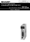
1
Version 1.1
Produced in April, 2002
Sharp Programmable Controller
NEW
Satellite JW50H/70H/100H
Model name
DeviceNet Master Module
User's Manual
JW-50DN
Thank you for purchasing this DeviceNet master module, the JW-50DN for use with the JW50H/70H/
100H programmable controller.
This manual describes the specifications, usage etc. of the DeviceNet master module JW-50DN.
Please familiarize yourself with the module by reading this user's manual thoroughly.
Keep this manual handy as well as the instruction manuals that come with each JW-50DN and
JW50H/70H/100H control module. We are confident that these manuals will be helpful whenever you
face a problem.
In addition to this manual, the following manuals are available for your further study.
JW50H/70H/100H
Control module
User's manual • hardware version
Programming manual
Note
- Should you have any questions or inquires, please feel free to contact one of our dealers, or
our service department.
- Copying this manual in part of in total is prohibited.
- The contents of this manual may be revised without notice.
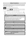
Safety Precautions
Read this manual and the attached documents carefully before installation, operation, maintenance and
checking, in order to use the machine correctly. Make sure you understand all of the machine operations,
safety information, and cautions before starting to use it. In this user's manual, safety precautions are
classified as "danger" or "caution," as follows.
Danger
: Incorrect handling may lead to death or serious injury.
Caution
: Incorrect handling may lead to property damage or injury.
Even when a
Caution is given, serious problems may be experienced, depending on
the circumstances. In all cases, important points are discussed. Be sure to follow the
advice given.
The symbols that prohibit action or show a required action are explained below.
: This means don't. For example, when disassembly is prohibited, you will see a
.
: This means an action is required. For example, a required grounding is shown as a
1)
Installation
Caution
- Use this device only in the environments specified in the leaflet, instruction manual, and
user's manual.
Electric shock, fire or malfunction may occur when used at high temperature, in high
humidity, in a dusty or corrosive atmosphere, or when vibration or shock loading are present.
- Install the device according to the instruction manual and the user's manual.
Incorrect installation may cause the device to fall, breakdown, or malfunction.
- Never allow wire trimmings or foreign matter to and on the device.
If they do a fire may break out, breakdown or a malfunction may occur.
2)
Wiring
Caution
- All wiring and connections should be done by a qualified electrician.
Incorrect wiring may lead to a fire, a breakdown of the product or an electric shock for the
user.
3)
Use
Danger
- Assemble an emergency stop circuit and interlock circuit outside of the programmable
controller. Otherwise a machine may malfunction or be damaged by a problem with the
programmable controller.
Caution
- Changing a program during operation, or forcing a "Run" or "Stop" command during
operation should only be done with particular care and only after confirming the safety of
such an operation. Incorrect operation may lead to damage or cause an accident.
4)
Maintenance
Disassembly prohibited
- Don't disassemble or modify the modules.
A fire, damage or malfunction may result.
.
Table of contents
Chapter 1: Outline ...................................................................................................... 1-1
Chapter 2: Handling Precautions ............................................................................. 2-1
Chapter 3: System Configuration ...................................................................... 3-1 to 7
[1] Network names and functions ........................................................................................
[2] Connection method .........................................................................................................
[3] Cable length ....................................................................................................................
[4] Power supply ..................................................................................................................
[5] Communication related devices ......................................................................................
3-2
3-3
3-4
3-5
3-6
Chapter 4: Installation Method ........................................................................... 4-1 to 3
[1] Installation of cable for option module ............................................................................ 4-1
[2] Installation of JW-50DN .................................................................................................. 4-2
Chapter 5: Connection (Wiring) Method ........................................................... 5-1 to 3
[1] Preparing a communication cable .................................................................................. 5-1
[2] Connecting a communication cable ................................................................................ 5-3
Chapter 6: Description of switch and lamp, setting system memory .......... 6-1 to 12
6-1 Name and function of switch and lamp ............................................................................... 6-1
(1) Display panel ............................................................................................................. 6-2
(2) Module address switch: UNIT ADRS ........................................................................ 6-3
(3) Node address switch: NODE ADRS .......................................................................... 6-3
(4) SCAN switch ............................................................................................................. 6-4
(5) Termination resistance: TERMINATOR ..................................................................... 6-4
(6) Function switch SW6 ................................................................................................. 6-5
6-2 Setting system memory ...................................................................................................... 6-6
(1) Top address of the I/O table ...................................................................................... 6-7
(2) Top address of the diagnosis table ............................................................................ 6-7
(3) Top address of the Explicit message table ................................................................ 6-7
(4) Top address of the scan list table .............................................................................. 6-7
(5) I/O data allocation system when editing the scan list ................................................ 6-8
(6) I/O data allocation system when editing the scan list ................................................ 6-8
(7) Explicit message list .................................................................................................. 6-8
(8) Communication monitor time (ISD, EPR) .................................................................. 6-9
(9) Output status of the slave module when the control module stops operation ........... 6-9
(10) Top address of the I/O table (when in the slave mode) ......................................... 6-10
(11) Number of I/O bytes (when in the slave mode) ..................................................... 6-10
(12) Restore/clear the slave area when a communication error occurs (when used in the slave
mode) .................................................................................................................... 6-10
6-3 Table of switches and system memory settings ................................................................ 6-11
[1] When the JW-50DN is used in the master mode ........................................................... 6-11
[2] When the JW-50DN is used in the slave mode ............................................................ 6-12
Chapter 7: I/O Message Function ...................................................................... 7-1 to 9
7-1 Input/output data table allocation ........................................................................................
[1] Address order allocation .................................................................................................
[2] Even number allocation ..................................................................................................
[3] Allocation in the order in which vacant nodes are occupied ...........................................
7-2 Editing the scan list .............................................................................................................
[1] Editing procedure ............................................................................................................
[2] Scan list data table .........................................................................................................
7-1
7-2
7-4
7-6
7-8
7-8
7-9
Chapter 8: Explicit Message Function .............................................................. 8-1 to 4
[1] Details of the Explicit message data table (requests) .....................................................
[2] Details of the Explicit message data table (responses) ..................................................
[3] Parameter addresses for the Explicit message data table (requests, responses) ..........
[4] Example ..........................................................................................................................
8-1
8-2
8-3
8-4
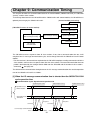
Chapter 9: Communication Timing ................................................................... 9-1 to 2
[1] When the I/O message communication time is shorter than the JW50H/70H/100H cycle
operation time ................................................................................................................. 9-1
[2] When the I/O message communication time is longer than the JW50H/70H/100H cycle
operation time ................................................................................................................. 9-2
Chapter 10: Error Handling ............................................................................ 10-1 to 13
10-1 Display lamp ................................................................................................................... 10-1
[1] Error code ..................................................................................................................... 10-2
[2] Display of node addresses ........................................................................................... 10-4
10-2 Diagnostic data table ...................................................................................................... 10-5
10-2-1 When JW-50DN is master mode ................................................................................. 10-5
[1] Diagnostic data table details ......................................................................................... 10-5
[2] Diagnostic data table addresses ................................................................................... 10-6
10-2-2 When the JW-50DN is used in the slave mode .......................................................... 10-11
10-3 JW-50DN status when the control module has stopped operation
or error has occurred .................................................................................................... 10-13
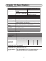
Chapter 11: Specifications ............................................................................... 11-1 to 2
Chapter 1: Outline
The JW-50DN DeviceNet master module is an interface module used to connect a JW50H/70H/100H
programmable controller to a DeviceNet in a network.
- This module is equipped with I/O message function (Polling I/O function, Bit Strobe function) and Explicit
message functions, among the many functions available with DeviceNet devices.
- In addition to the master function, it has slave function and can be used as a data link system.
- When used in master mode, this module can be connected to up to 63 slave nodes.
The maximum total number of I/O points is 4096.
- By integrating Sharp's unique scan list editing function, there is no need to configure the JW-50D's
settings.
DeviceNet is a trademark of the ODVA (Open DeviceNet Vendor Association).
1-1
Chapter 2: Handling Precautions
Make sure to follow the precautions below while using this module.
(1) Storing
Do not store the JW-50DN in the following conditions.
1. In direct sunlight, or ambient temperatures exceeding the range of 0 to 55 ˚C.
2. In relative humidity that exceeds the range of 35 to 90%, or in a location subject to sudden
temperature changes which may cause condensation.
3. Near corrosive or inflammable gas.
4. In a location subject to vibration or hard jolts.
(2) Installation
Make sure to turn OFF the power to the JW50H/70H/100H before removing or installing a module on
the basic rack panel.
(3) Treatment
Make sure to follow the precautions below while using this module.
1. Holes are provided in the cabinet for ventilation, to prevent the temperature from increasing. Do
not block the ventilation holes. Good ventilation is necessary.
2. When a problem or an abnormal condition such as overheating, fumes, or smoke are observed,
stop the operation immediately, and call your dealer or our service department.
3. Make sure to turn OFF the power to the JW50H/70H/100H before changing the switch settings.
An imprudent changeover of the switches may cause a malfunction.
(4) Static electricity
In extremely dry circumstances, the human body may have excessive static current. This excessive
static current may damage parts in the JW-50DN's PC board. Therefore, prior to accessing the JW50DN, touch your hand to a grounded piece of metal to discharge the static current in your body.
(5) Cleaning
Use a clean, dry cloth when cleaning the JW-50DN. Do not use volatile chemicals such as thinner or
alcohol as it may result in deformation and color fading.
2-1
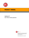
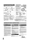
Chapter 3: System Configuration
The JW-50DN can be used to communicate as a master or slave module in a DeviceNet.
Connection example
JW50H/70H/100H
JW-50DN
(Master
mode)
JW-50DN
JW-50DN
S0
S1
S2
S3
S4
S5
S6
S7
S0
S1
S2
S3
S4
S5
S6
S7
MS
NS
SD
RD
FT
PT
JW50H/70H/100H
JW-50DN
JW-50DN
(Slave
mode)
MS
NS
SD
RD
FT
PT
S0
S1
S2
S3
S4
S5
S6
S7
JW-50DN
(Master
mode)
MS
NS
SD
RD
FT
PT
Power Terminating
resistance
tap
Cable (Trunk)
Slave
Cable (Trunk)
T branch
system
tap
Power Terminating
tap
resistance
Slave
Slave
Cable (Branch line)
Power supply for
communication
(24 VDC)
Slave
Slave
Slave
Power supply for
communication
(24 VDC)
- Select the basic operation mode (master/slave) using the SW6-3 switch on the JW-50DN.
- Up to two JW-50DN modules can be installed in the same rack panel.
(Two master modules or two slave modules can also be installed)
- Supply master modules, slave modules, cables, T branch taps, power taps, and termination
resistors that are compatible with DeviceNet, for use in a system containing a JW-50DN.
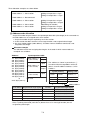
SHARP’s modules applied for the DeviceNet (master/slave)
Model name
Master
Slave
PLC to install
JW-50DN
○
○
JW-20DN
○
○ (V 2.1 or more) JW20H, JW30H
JW-32CUM1
○
−
JW30H
JW-32CUM2
○
○
JW30H
JW-32CV3
○
○
VME built-in controller
Z-337J
○
○ (V 2.1 or more) J-board
Z-338J
○
○ (V 2.1 or more) (Z300/Z500 series)
JW50H, JW70H, JW100H
○:Usable, Inside parenthesses:Software version
3-1
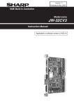
[1] Network names and functions
This section lists the device names and functions used in DeviceNet networks.
Network example
Terminating
resistance
Power
tap
Multi-drop
method
T branch
method
Multi-drop
Branch line method
Node
Power supply for
communication
(24 VDC)
T branch
system
Trunk
Node
Branch
line
Node
Terminating
resistance
Branch line
Node
Node
T branch
system
Multi-drop
method
Branch line
Node
Node
Names
Node
-
Trunk
Branch line
Connection
method
Terminating
resistance
-
-
-
Power supply
for
communication
Node
Node
Functions
Master and slave nodes are available on the DeviceNet.
Master: Integrates external I/Os from each slave.
Slave: provides connections for external I/Os.
Since there are no restrictions in allocating a master and slaves, you can arrange
nodes at any location shown above.
Cable with a terminating resistance at both ends.
Normally, the cable connecting the terminals the furthest distance apart will be a
trunk cable.
Use a five conductor cable (2 signal wires, 2 power wires, 1 shield).
The trunk length is not always equal to the maximum length of the network.
A cable branching off the trunk.
You can add new branch lines to the trunk
Use a five conductor cable (2 signal wires, 2 power wires, 1 shield).
There are two methods for connecting nodes: T branch and Multi-drop.
T branch method: Uses T branch taps for up to three separate branch lines.
Multi-drop method: Connects a node directly to a trunk or to a branch line.
Both the T branch method and the Multi-drop method can be used in the same
network.
Install a terminating resistance (121ohm) on both ends of the trunk, in order to
reduce signal reflection and stabilize the communication.
JW-50DN has an integrated terminating resistance which can be enabled or
disabled.
Communication power should be supplied to the communication connector on each
node through the five conductor cable.
Use only a power supply dedicated exclusively to communications. Do not share
this power supply with other devices.
3-2
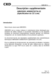
[2] Connection method
There are two methods for connecting nodes: T branch and Multi-drop.
(1) T branch method
You can make up to three branch lines away from a trunk or a branch line. Use a T branch tap to
branch off.
T branch tap
T branch tap
Branch
line
Trunk
Branch line
Branch line
Node
Node
Node
Node
Node
Node
(2) Multi-drop method
Connect a node directly to a trunk or a branch line.
Multi-drop
Multi-drop
Branch line
Trunk
Node
Node
3-3
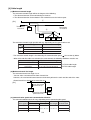
[3] Cable length
(1) Maximum network length
The maximum network length will be the longest of the following:
1. The distance between the two terminating resistances
2. The distance between the two nodes in the network that are the farthest apart
1
[Ex.]
Terminating
resistance
Node
Terminating
resistance
2
Node
Node
Node
Node
The maximum network length possible will vary, depending on the type of cable used.
Cable type
Thick cable: 5 conductors
1
Thin cable: 5 conductors
Maximum network length
500 m
100 m
2 Thin cable: 5 conductors
100 m
- The maximum network length is also limited by the communication speed.
See section (3) below.
- When thick and thin cables are mixed in the same network, the following conditions must be met.
Communication speed
500 k bits/s
250 k bits/s
125 k bits/s
Maximum network length
(A + B) is less than 100 m
(A + 2.5 x B) is less than 250 m
(A + 5 x B) is less than 500 m
A: Thick cable length
B: Thin cable length
(2) Maximum branch line length
The maximum branch line length is 6 m.
- You can make a new branch line from a branch line.
However, the maximum distance between the branch point on the trunk and the end of the most
distant branch line should not be more than 6 m.
[Ex.]
Branch line length
(Maximum 6 m)
Node
Node
Branch line length
(Maximum 6 m)
Node
(3) Communication speed and communication distance
The communication distance will vary, depending on the communication speed.
Communication speed
500 k bits/s
250 k bits/s
125 k bits/s
Maximum network length
Branch Total length of
Thick cable
Thin cable line length branch lines
100 m or less
39 m or less
250 m or less 100 m or less 6 m or less 78 m or less
500 m or less
156 m or less
3-4
[4] Power supply
Connect the communication power supply to the trunk.
Two of the five conductors in the cable used for trunk and branch lines are assigned to carry power for
communication (24 VDC).
The following methods can be used to connect a communication power source to the trunk.
Use a T branch tap or a power tap.
Power supply for
communication
T branch tap or power tap
(24 VDC)
When connecting one
power supply device
to a network
Terminating
resistance
Terminating
resistance
Node
Use a power tap.
Power supply for
communication
(24 VDC)
Power tap
Node
Node
Power supply for
communication
(24 VDC)
Power tap
When connecting
more than one power
supply device to a
Terminating
network
resistance
Terminating
resistance
Node
Node
Node
Node
Node
Configuration of a power tap
Power tap
Five
conductor
cable
V+ (24V)
Signal wire CAN H
Ground 24 VDC power source
terminal V- V+
Schottky
barrier
diode
Fuse
Fuse
V+ (24V)
Signal wire CAN H
Shield
Signal wire CAN L
V- (0V)
Shield
Signal wire CAN L
V- (0V)
Remarks
- Do not share the communication power source with other devices.
3-5
Five
conductor
cable
[5] Communication related devices
In addition to master and slave nodes, the following devices can be used in this system: cables, T
branch taps, power taps, communication connectors, terminating resistances, and communication
power supplies. Listed below are the models of devices currently available (by manufacturer).
(1) Cable
Thick or thin five conductor cable is available.
Number of ManufaLength
Outside
Type
Model
conductors cturers
(m)
diameter (mm)
Five
Thick 1485C-P1-A50
50
11.6 to 12.1
AllenThin 1485C-P1-C150
150
6.9
Signal lines: 2 Bradley
Power source
Thick
DCA2-5C10
100
11.6 to 12.1
lines: 2
Omron
Shield: 1
Thin
DCA1-5C10
100
6.9
Main use
Trunk
Branch line or trunk
*
Trunk
Branch line or trunk
*
* When using a thin cable for a trunk, make sure that the trunk is not more than 100 m long.
(2) T branch tap
You can connect up to three new branch lines off a single existing branch line.
Model
DCN1-1C
Number of connectors
Three (this tap is used to
connect one new branch line)
Five (this tap is used to
DCN1-3C connect three new branch
lines)
Remarks
Manufacturer
- Has three connectors for connecting up
to three new lines
- Connects to a terminating resistor
Omron
- Has five connectors for connecting up
to five new lines
- Connects to a terminating resistor
(3) Power tap
This tap is used to supply power to the five conductor cable when connecting more than one
communication power supply to a single network .
Model
Specifications
Power tap
1485T-P2T5-T5 With a reverse current prevention
function and ground terminal
Manufacturer
Allen-Bradley
- This tap can be used to connect a single communication power supply to a network.
In this case, you can also use a T branch tap (above), in addition to the power tap.
- When connecting a power supply device to a single network, use this multi-outlet power strip to
prevent reverse current flow to the power supply, due to a difference in potential.
(4) Communication connector
This module contains one BLZ5.08/5F AU-DN (with a screw for securing the connector made by
Nihon Weidmuller).
See page 5-2 to 5-3.
(5) Terminating resistance
Model
Remarks
DRS1-T Terminal block type terminating resistance (121 ohms)
---Terminating resistance attached to the T branch tap (121 ohms)
3-6
Manufacturer
Omron
(6) Communication power supply
Make sure to use a power supply device for communication that conform to the specifications below.
Item
Specifications
Output voltage
24VDC ±1%
Output current
16A or less
Input variation
0.3% max.
Load variation
0.3% max.
Influence of ambient temperature
0.03%/℃ max.
Input voltage
100 to 1200 V
Input frequency
47 to 450 Hz
Output ripple
250 mVp-p
Output side capacity
7000μF max.
Ambient temperature
Operation: 0 to 60℃, Storage: −40 to 85℃
Instantaneous maximum output current 65A or less (peak)
Overvoltage protection
Provided
Overcurrent protection
Provided(Max. current: 125%)
Start up time
250 ms until 5% value of final output current
Overshoot while starting up
0.2% max.
Insulation
Between output - AC, and output - frame ground
Conformity
Essential: UL
Recommend: FCC Class B, CSA, TUV, VDE
Ambient humidity
30 to 90% (without dewing)
Surge current capacity
Up to 10 %
3-7
Chapter 4: Installation Method
[1] Installation of cable for option module
Install the optional cable on the basic rack panel that installed JW-50DN.
Optional cables and a basic rack panel are available in various combinations, as shown below.
Cable type for option module
Cable for option module
Maximum number of JW-50DN
that can be installed
ZW-2CC
ZW-4CC
ZW-6CC
Max. 2 sets
Rack panel type
Model name of the rack
panel on which optional
cable is installed
JW-4BU
JW-6BU
JW-8BU
JW-13BU
Cable for option module
ZW-2CC
ZW-4CC
ZW-6CC
○ : Can be installed
× : Cannot be installed
[Example] In case that install a rack panel JW-4BU to ZW-2CC
Rack panel JW-4BU
Pay attention to the
installation orientation
of the connector.
Cable for
option module
ZW-2CC
6 securing screws
(Attached to cable for
option module)
4-1
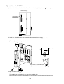
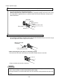
[2] Installation of JW-50DN
(1) Set switch SW6 on the side of the JW-50DN main housing. (Setting details
See page 6-5.)
1
2
3
4
5
6
7
8
9
0
SW6
ON
O
F
F
Switch SW6
1 2 3 4 5 6 7 8 9 10
OFF
(Side of the JW-50DN main housing)
(2) Install the JW-50DN into a rack panel using the two attachment screws.
Before installation or removal, make sure to shut OFF the power supply to the PC.
[Example] Install on rack panel JW-4BU
Module
Rack panel
Appearance when ZW-2CC
optional cable is installed.
+
Philips screwdriver
This module can be installed in any one of the optional slots.
Be careful not to bend the connector pins on the module by applying too much force to them.
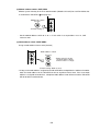
4-2
Optional slots have each port numbers. When an error occurs, the JW50H/70H/100H (control module)
stores the port number corresponding to the error occurred module into system memory #050 in the PC.
This is applied only error code 53: Optional error.
(JW-13BU)
2 3 4 5 6 7
Control module
Port number
4-3
Chapter 5: Connection (Wiring) Method
This chapter describes how to connect the JW-50DN to a DeviceNet.
[1] Preparing a communication cable
Prepare the communication cable by following the steps below to attach the connector.
1 Remove approximately 30 mm of insulation from the communication cable
- Remove the insulation without damaging the coaxial shield around the cable.
Do not remove more insulation than necessary, as it may cause a short-circuit.
Communication cable
Approximately
30 mm
2 Unwrap the wires in the coaxial shield carefully
- Under the coaxial shield there is one signal line, one power line, and one ground line. The signal
line and power lines are wrapped in aluminum tape.
Aluminum tape
Ground line
3 Cut off the excess coaxial shield and peel back the aluminum tape on the signal line and power line.
4 Remove the insulation from the signal and power lines until enough bare wire is exposed to fit into
a crimp-style terminal.
- Twist the strands of wire in the signal and power lines tightly, in order to slide them into a terminal.
The length needed to fit into a crimp-style terminal.
5Crimp a terminal on each of the individual lines and then insulate it using vinyl tape or shrink tubing.
Cable
Crimp-style terminal
- Shown below are the recommended crimp-style terminals
Recommended crimp-style terminals
AI series made by Phoenix Contact
Special tool
ZA3 made by Phoenix Contact
TC series made by Nichifu
- For thin wire : TME TC-0.5
NH-32
- For thick wire : TME TC-2-11 (power line)
TME TC-1.25-11 (communication line)
To the next page
5-1
From the previous page
6 Insert the signal line, power line, and the ground line into the appropriate connector holes.
- Insert the wires from the top down, in the following order: red, white, ground , blue, and black.
Pay strict attention to the connector orientation.
- Before inserting the wires, loosen the screws on the connector enough to insert the wires easily.
- The JW-50DN is supplied with one set of BLZ5.08/5F AU-DN (with connector securing screw:
Nihon Weidmuller).
Connector
Red (V+)
White (CAN H)
Ground
Communication cable
Blue (CAN L)
Black (V —)
7 Secure each wire tightly using the wire retention screws of the connector.
- Use a miniature flat blade screwdriver which has the same diameter from the neck all the way to
the end. Tighten the screws using 0.5 N-m of force.
Miniature flat blade
screwdriver
Cable securing screw
• When connecting two thin cables in a multi-drop system
Insert the wires from each cable with the same color insulation into the same hole.
- Crimp a terminal to the tip of the two wires.
Remarks
- Before connecting the communication cable, make sure to turn OFF the power to the JW50H/70H/
100H, all slave stations, and the communication power supply.
- Do not pull hard on the communication cable since the connector can be pulled off or disconnected
easily.
5-2
[2] Connecting a communication cable
This section describes how to plug a connector that has been installed on the communication cable into
the JW-50DN.
Match the orientation of the connector on the cable with the female connector on the JW-50DN and
insert the male cable connector as far as it will go. After inserting it all the way, tighten the screws on the
male connector. The appropriate tightening torque is 0.3 N-m of force.
JW -5 0 D N
MS
S0
S1
S2
S3
S4
S5
S6
S7
NS
SD
RD
FT
PT
.
NODE ADRS
×10
×1
.
UNIT ADRS
SCAN
R
TERMINATO
ON
OFF
Communication connector
Screw (2)
Red (V+)
White (CAN H)
Ground
Communication cable
Blue (CAN L)
* Cable connector
Black (V —)
* One male connector is supplied with the JW-50DN.
- Model name: BLZ5.08/5F AU-DN (made by Nihon Weidmuller)
5-3
Chapter 6: Description of switch and lamp,
setting system memory
6-1 Name and function of switch and lamp
Front side
JW-50DN
Display panel
- Shows the module’s
operating status. => See (1)
S0
S1
S2
S3
S4
S5
S6
S7
MS
NS
SD
RD
FT
PT
NODE ADRS.
456
901
78
23
×10
456
78
901
Module address switch
- Select a system memory
area in which to specify the
operating conditions. => See (2)
23
Node address switch
- Specify node address (0 to 63)
=> See (3)
×1
UNIT ADRS.
456
901
78
23
SCAN
SCAN switch
TERMINATOR
- Create scan list. => See (4)
ON
OFF
Termination resistance switch
- Enable/disable the termination
resistance. => See (5)
1 2 3 4 5 6 7 8 9 10
O
F
F
Function switch SW6
1
2
3
4
5
6
7
8
9
0
SW6
Rear side
1 2 3 4 5 6 7 8 9 10 OFF
O
F
F
1
2
3
4
5
6
7
8
9
0
SW6
ON
- Select between master and
slave modes, and specify the
communication speed.
=> See (6)
6-1
(1) Display panel
Shows the module’s operating status by turning ON and OFF, and blinking.
JW-50DN
S0
S1
S2
S3
S4
S5
S6
S7
Lamp name
MS
NS
SD
RD
FT
PT
S7 to S0
MS
NS
SD
RD
FT
PT
Color
Green/Red
Green/Red
Red
Red
Red
Red
Red
Display panel on the JW-50DN
- The areas are the locations of the lights.
Operation details
Indicates the module's status.
For details, see the table
below.
Indicates the network status.
Lights when sending data.
Lights when receiving data.
Lights when the module is faulty.
Lights when the module is in the protected mode.
Displays error codes and the node address when an error occurs.
Details of the MS/NS
Lamp
name
Color
Green
MS
(Module
Status)
Red
---
Status
ON
Blinks
ON
Blinks
Normal
Not yet set
Hardware error
Abnormal setting
OFF
No power supplied
ON
On-line/connected
Blinks
On-line/not yet
connected
ON
Communication
error 1
Green
NS
(Network
Status) Red
Blinks
---
Details
OFF
Communication
error 2
Off-line/power OFF
status
6-2
The JW-50DN is functioning normally.
Currently reading the switch settings.
The JW-50DN has a hardware error.
Mis-set switches.
- Hardware error in the JW-50DN.
- No power is supplied to the JW-50DN.
- Currently resetting.
- Waiting for initialization.
The network is functioning normally
(communication has been established)
Though the network is functioning normally,
communication has not yet been established.
- Communication error (the module detected an
error indicating that communication on the
network is not possible).
- A node address has been used twice.
- Detected Bus Off.
A slave station or some other stations are causing
a communication error.
There are no nodes other than the JW-50DN.
(2) Module address switch: UNIT ADRS
Allocate system memory in the PLC control module (JW50H/70H/100H) for each DeviceNet that
See page 6-6.
is used with the JW-50DN.
Module No. switch
NODE ADRS.
UNIT ADRS.
456
23
901
×10
456
78
901
456
901
78
78
23
23
×1
UNIT ADRS.
456
(Default setting: 0)
901
78
23
- Set the module address switch to "0" or "1." If this switch is set to positions "2" to "9", it will
cause an error.
(3) Node address switch: NODE ADRS
Assign a node address from 0 to 63 (decimal)
Node address switch
NODE ADRS.
456
23
×1
78
456
456
23
901
78
NODE ADRS.
901
×10
23
901
78
×10
UNIT ADRS.
456
456
78
901
901
78
- Upper switch is for the
10’s digit and the lower
switch is for the 1’s digit.
23
23
×1
(Default setting: Both set to 0)
- As long as the node address assigned to the JW-50DN does not duplicate the address of another
node, the node address on the JW-50DN can be set anywhere from 0 to 63. If the same node
address is assigned to two devices, a duplicate node address error will occur and the JW-50DN
will not be able to communicate.
6-3
(4) SCAN switch
When the switch 6-7 (page 6-5) is set to "Protection OFF" or a "Busoff" error occurs, keep press
the SCAN switch for three seconds, the JW-50DN executes the following procedures.
When used in the master mode
Re-reading settings of the switches and
system memory
(If there is no error)
When used in the slave mode
Re-reading settings of the switches and
system memory
Edit the scan list
- When the "Busoff" error occurs, there is a fault on the communication. In this case, turn OFF/ON the
PLC power or keep pressing the SCAN switch for longer than three seconds regardless of the
settings of the protect, the JW-50DN is shut off connection, and is issued connection again. If there
is no problem on the communication, the JW-50DN can communicate normally.
UNIT ADRS.
456
901
78
SCAN switch
23
SCAN
TERMINATOR
ON
OFF
(5) Termination resistance: TERMINATOR
If the JW-50DN is the final module in the DeviceNet communication trunk line, turn this switch ON.
UNIT ADRS.
456
901
78
23
SCAN
Termination resistance switch
(Factory setting: ON)
TERMINATOR
ON
OFF
6-4
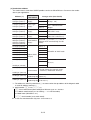
(6) Function switch SW6
O
F
F
1
2
3
4
5
6
7
8
9
0
SW6
1 2 3 4 5 6 7 8 9 10
ON
OFF
Select basic operation mode (master/slave), communication speed etc.
6
5
4
3
2
1
Basic operation
Switch No.
mode
Master Slave
SW6
Set details
Operation when a slave communication error occurs
- Select whether or not to continue operation of JW50H/70H/100H control module when
a communcation error occurs while communicating with a slave station.
1
○
1
OFF The control module continues operation.
The control module stops operation and enters the program mode.
ON
(Default setting)
Synchronous/asynchronous operation
- Select whether or not to synchronize the communication with the operation cycle.
ー
2
2
OFF Not synchronized.
ON Synchronized with the operation (default setting)
Note: The synchronization operation is only possible with one other control module, such
as the JW-10CM and JW-20CM communication modules. Therefore, if more than
one module is used in synchronization mode, the synchronized operation is not
supported.
Basic operation mode
- Select the basic operation mode (master/slave) of JW-50DN.
○
○
3
3
OFF
ON
Master (default setting)
Slave
Communication speed
- Select a baud rate: 125 kbps, 250 kbps, or 500 kbps.
○
4
5, 6
SW6-6
SW6-5
OFF
OFF
125 kbps
Band rate
(default setting)
OFF
ON
ON
OFF
250 kbps
500 kbps
ON
ON
Prohibited
setting
Protection function (ON/OFF)
- Select whether to use the protection function.
○
○
5
7
OFF Protection ON (Factory setting)
ON Protection OFF
- See page 6-4, 7-8.
Communication monitor time
Communication monitor time (ISD, EPR) is timeout time of communication. Select either
of "normal mode" and "long mode." However, only if the following system memory is set
to 00 (HEX) (see page 6-9), this function can be set.
ー
ー
ー
6
ー
8
4, 9, 10
OFF Normal mode (Factory setting)
ON Long mode
- #1624 to #1627 (When module address is "0")
- #1724 to #1727 (When module address is "1")
Do not use (set to OFF at the factory)
( ○ : Enable, ー : Disable)
6-5
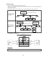
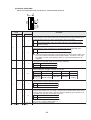
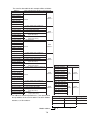
6-2 Setting system memory
The table of JW-50DN system memory settings is shown below.
Basic operation
mode
Setting value of module address
switch
Setting item
Master
Slave
0
1
O
-
Top address of I/O table
#1600 to #1603
#1700 to #1703
(1)
O
O
Top address of diagnostic table
#1604 to #1607
#1704 to #1707
(2)
O
-
Top address of Explicit message
table
#1610 to #1613
#1710 to #1713
(3)
O
-
Top address of scan list table
#1614 to #1617
#1714 to #1717
(4)
O
-
I/O data allocation system when
editing scan list
#1620
#1720
(5)
O
-
Data length when editing scan list
#1621
#1721
(6)
O
-
Request explicit message
#1622
#1722
(7)
O
-
ISD (communication monitor time)
#1624
#1625
#1724
#1725
#1726
#1727
#1730
(9)
See page
6-7.
See page
6-8.
(8)
O
-
EPR (communication monitor time)
#1626
#1627
O
-
Slave module output status when
the control module is not operating.
#1630
-
O
Top address of I/O table (when used
#1660 to #1663
as slave module)
#1760 to #1763
(10)
-
O
Number of I/O bytes (when used as
slave module)
#1664 to #1667
#1764 to #1767
(11)
-
O
Latch/clear slave area when
communication error occurs (when
used as slave module)
#1670
#1770
(12)
See page
6-9.
(○: Enable, ー: Disable)
Remarks
- Within the system memory range #1600 to #1777, make sure to set the memory to 00(HEX) all the
addresses except the above.
- If you will not be using the "top address of the diagnosis table," "top address of the Explicit
message table," and "top address of the scan list table," make sure to disable them by setting
them to 01(HEX). If you enable them 00 (HEX) while leaving the top address set to 00(HEX), the data
will overlap from the top address (コ0000)], and cause a malfunction. Be especially careful the
"top address of the diagnosis table" can be enabled when the JW-50DN is used in the slave
mode.
6-6
See page
6-10.
(1) Top address of the I/O table
When the JW-50DN is used in the master mode, this system memory location is used to store the
top address of the I/O table (max. 512 bytes) that will be used for I/O message functions. (I/O data
table
See page 7-1.)
Module address switch setting value
0
1
Setting item
Setting range
#1600 to #1601
#1700 to #1701
File address
000000 to 177777(OCT)
#1602
#1702
File number
00 to 07(HEX)
#1603
#1703
---
00(HEX) fixed
(2) Top address of the diagnosis table
This system memory location is used to store the top address and to enable/disable the diagnosis
table (256 bytes in the master mode, 128 bytes in the slave mode) which is used to check the
communication status of the nodes (master, slave). The diagnosis table can be used in both the
master and slave modes. (Diagnostic data table
Module address switch setting value
0
1
See page 10-5.)
Setting item
Setting range
#1604 to #1605
#1704 to #1705
File address
000000 to 177777(OCT)
#1605
#1706
File number
00 to 07(HEX)
#1607
#1707
Enable/disable
00(HEX): Enable, 01(HEX): Disable
(3) Top address of the Explicit message table
When the JW-50DN is used in the master mode, this system memory location is used to store the
top address of the Explicit message table (256 bytes) which is used for the Explicit message
function. (Explicit message data table
Module address switch setting value
0
1
See page 8-1.)
Setting item
Setting range
#1610 to #1611
#1710 to #1711
File address
000000 to 177777(OCT)
#1612
#1712
File number
00 to 07(HEX)
#1612
#1713
Enable/disable
00(HEX): Enable, 01(HEX): Disable
(4) Top address of the scan list table
When the JW-50DN is used in the master mode, this system memory location is used to store the
top address of the scan list table (512 bytes) which is used when editing the scan list. (Scan list
data table
See page 7-9.)
Module address switch setting value
0
1
Setting item
Setting range
#1614 to #1615
#1704 to #1705
File address
000000 to 177777(OCT)
#1616
#1716
File number
00 to 07(HEX)
#1617
#1717
Enable/disable
6-7
00(HEX): Enable, 01(HEX): Disable
(5) I/O data allocation system when editing the scan list
This system memory is allocated by editing a scan list, if the JW-50DN is used in the master mode.
(Details in each allocation system => See page 7-1.)
Module address
switch setting value
0
#1620
Setting item
Setting range
1
#1720
00(HEX): Allocate in time order
Allocation system 01(HEX): Allocate evenly
02(HEX): Allocate in order of securing empty node
of I/O data
area
(6) I/O data allocation system when editing the scan list
This system memory is allocated by editing a scan list (with allocation of even distance / allocation
in the order of securing empty node area), if the JW-50DN is used in the master mode.
(Description => See page 7-1.)
Module address
switch setting value
0
1
#1621
#1721
Setting item
Setting range
Data length when
editing scan list
1 to 64 bytes (001 to 100(OCT))
(7) Explicit message list
This is a system memory area used for the Explicit message function, when the JW-50DN is used
in the master mode. (Explicit message data function
Module address
switch setting value
0
1
#1622
#1722
Setting item
See page 8-1.)
Setting range
Request Explicit 00(HEX): Do not use Explicit message function
01(HEX): Use Explicit message function
message
6-8
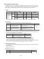
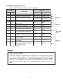
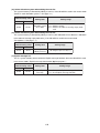
(8) Communication monitor time (ISD, EPR)
This system memory contains the "ISD" and "EPR" settings used for determining a communication
timeout, when the JW-50DN is used in the master mode.
ISD (InterScan Delay)
The ISD is the communication monitor time allowed after the master module sends a request to
a slave module until it receives a response from the last slave module.
When the time allowed for the ISD has elapsed without a response from the last slave, the JW50DN advances to the next communication cycle.
EPR (Expected Packet Rate)
The EPR is the communication monitor time allowed after a master module sends a request to a
slave module until it receives a response from all of the slave modules.
If one or more of the slave modules fails to return a response within the time allowed, a commu
nication error occurs.
Module address
switch setting value
Setting item
Setting range
0
1
#1624 to
#1625
#1724 to
#1725
2 to 65534 ms (2 to 65534(DCM))
ISD
- Specify in units of 2 ms.
(communication
- A setting of "0" enables the reading of the
monitor time)
setting on SW6-8. => See below
#1626 to
#1627
#1726 to
#1727
4 to 65532 ms (4 to 65532(DCM))
EPR
- Specify in units of 4 ms.
(communication
- A setting of "0" enables the reading of the
monitor time)
setting on SW6-8. => See below
Communication monitor time when "0" is entered in the module address switch setting
Communication monitor time (ms)
Number of
Normal mode (when SW6-8 is OFF) Long mode (when SW6-8 is ON)
slave
modules
ISD
EPR
ISD
EPR
1 to 15
40
16 to 31
60
32 to 47
80
48 to 63
100
80
1000
120
1500
160
200
- The communication time can be measured using a commercial DeviceNet analyzer.
- For details about switch 6-8, see page 6-5.
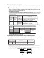
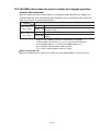
(9) Output status of the slave module when the control module stops operation
When the JW-50DN is used in the master mode, this system memory location is used to select the
data sent to the slave modules if a JW50H/70H/100H control module stops operation (enters the
program mode).
Module address
switch setting value
0
1
#1630
#1730
Setting item
Setting range
Output status of slave module when 00(HEX): Send idle data. *
01(HEX): Clear
control module stops operation
* For details about slave station operation when a slave station receives idle data, see the instruction manual for reach slave station.
The areas shown in gray in the figure below can be set to "send/clear idle data" when the control
module stops operation.
Master module: JW-50DN
Input data
Output data
Input data
Output data
6-9
Slave module 1
Input data
Output data
Slave module 2
Input data
Output data
(10) Top address of the I/O table (when in the slave mode)
This system memory location is used to store the top address of the I/O table when the JW-50DN is
in the slave mode.
Module address switch setting value
0
1
Setting item
Setting range
#1660 to #1661
#1760 to #1761
File address
000000 to 177777(OCT)
#1662
#1762
File number
00 to 07(HEX)
#1663
#1763
----
00(HEX): Fixed
(11) Number of I/O bytes (when in the slave mode)
This system memory location is used to store the number of input bytes (0 to 127 bytes) and output
bytes (0 to 127) when the JW-50DN is in the slave mode.
Module address
switch setting value
Setting item
0
1
#1664
#1764
Number of input (sending) bytes
#1665
#1765
----
#1666
#1766
Number of output (sending) bytes
#1667
#1767
----
Setting range
0 to 127 bytes (0 to 177(OCT))
00(HEX): Fixed
0 to 127 bytes (0 to 177(OCT))
00(HEX): Fixed
- The specified number of bytes are allocated from the top address in the I/O table (when used in the
slave mode) with input bytes being allocated first, followed by the area for the output bytes.
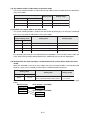
(12) Restore/clear the slave area when a communication error occurs (when used in the slave
mode)
When the JW-50DN is used in the slave mode, this system memory location is used to determine
whether a slave area is restored or cleared when a communication error occurs.
Module address switch
setting value
0
1
#1670
#1770
Setting item
Setting range
Preserve or clear the slave area
00(HEX): Latch
when a communication error occurs. 01(HEX): Clear
Slave areas, which select "latch or clear" when communication error occurs, are shown in gray
below.
Master module
Slave module 1 (JW-50DN)
Input data
Input data
Output data
Output data
Input data
Slave module 2 (JW-50DN)
Output data
Input data
Output data
6-10
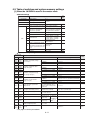
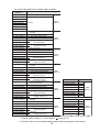
6-3 Table of switches and system memory settings
[1] When the JW-50DN is used in the master mode
Switch settings
Switch name
Set
value
Setting details
UNIT ADRS
Module address
0, 1
NODE ADRS (X10) Upper digit of node address
NODE ADRS (X1)
TERMINATOR
Lower digit of node address
Termination resistance
00 to 63
Set termination node to ON
1
Select CU operation status when OFF: Continue operation
an communication error occurs. ON: Stop operation
2
Select synchronize/asynchronize
OFF: Asynchronous calculation
between the communication
ON: Synchornous calculation
cycle and CU operation
3
Select master/slave mode
OFF (master mode)
OFF
4
Not used
Set to OFF
OFF
Select baud rate
5 (OFF), 6(OFF) = 125 kbps
5 (ON), 6(OFF) = 250 kbps
5 (OFF), 6(ON) = 500 kbps
7
Select protect mode
OFF: Not protection
ON: Protection
8
Select a communication monitor
time
OFF: Normal
- This will be used when ISD and
ON: Long
EPR in system memory are set
to 0.
9
Not used
Set to OFF
OFF
10 Not used
Set to OFF
OFF
5
6
SW6
System memory settings
Set value of
module address
0
Set details
1
#1600
#1601
Item
Set range
#1602
#1700
#1701 Top address of I/O table (occupy
#1702 max. 512 bytes)
#1603
#1703
#1604
#1605
#1606
#1704
#1705 Top address of diagnosis table
#1706 (occupy 256 bytes)
File number
00 to 07(HEX)
#1607
#1707
00(HEX): Enable, 01(HEX): Disable
00, 01(HEX)
#1610
#1611
#1710
#1711
File address
000000 to 177777(OCT) (Set with octal and word)
File address
000000 to 177777(OCT) (Set with octal and word)
File number
00 to 07(HEX)
---
Set to 00(HEX)
File address
000000 to 177777(OCT) (Set with octal and word)
#1612
Top address of Explicit message
#1712 table (occupy 256 bytes)
File number
00 to 07(HEX)
#1613
#1713
00(HEX): Enable, 01(HEX): Disable
00, 01(HEX)
#1614
#1615
File address
000000 to 177777(OCT) (Set with octal and word)
#1616
#1714
#1715 Top address of scan list table
#1716 (occupy 512 bytes)
File number
00 to 07(HEX)
#1617
#1717
00(HEX): Enable, 01(HEX): Disable
00, 01(HEX)
#1620
I/O data allocation system when
#1720
editing scan list
00(HEX): In order of allocation time,
01(HEX): Even allocation, 02(HEX):
00 to 02(HEX)
Allocate in order of empty node
secured area
#1621
#1721 Data length when editing scan list
1 to 64 bytes (when in order of
allocation time is selected)
001 to 100(HEX) (set with octal)
#1622
#1722 Request Explicit message
00(HEX): Use
01(HEX): Does not use
00, 01(HEX)
#1623
#1723 Not used
---
Set to 00(HEX)
#1624
#1625
#1724
ISD (communication monitor time)
#1725
#1626
#1627
#1726
EPR (communication monitor time)
#1727
2 to 65534 ms (in - A setting of
00002 to 65534(DCM) (Set with decimal and word)
"0" enables
units of 2 ms)
the reading of
4 to 65532 ms (in the setting on
00004 to 65532(DCM) (Set with decimal and word)
units of 4 ms)
SW6-8.
#1630
#1730
#1631
to
#1677
#1731
to
Not used
#1777
Slave output status when the control 00(HEX): Send idling data
01(HEX): Clear
module is stopped operation
---
6-11
00(HEX)
00(HEX)
00, 01(HEX)
Set to 00(HEX)
- See page 6-6 for the precautions.
Set
value
00(HEX)
[2] When the JW-50DN is used in the slave mode
Switch settings
Switch name
UNIT ADRS
Module address
NODE ADRS (X10)
Upper digit of node address
NODE ADRS (X1)
Lower digit of node address
TERMINATOR
SW6
Set
value
Setting details
0, 1
00 to 63
Termination resistance
Set termination node to ON
1
Select CU operation status when
Set to OFF
an communication error occurs. *1
OFF
2
Select synchronize/asynchronize
between the communication cycle Set to OFF
and CU operation *2
OFF
3
Select master/slave mode
Set ON (slave mode)
OFF
4
Not used
Set to OFF
OFF
Select baud rate
5 (OFF), 6(OFF) = 125 kbps
5 (ON), 6(OFF) = 250 kbps
5 (OFF), 6(ON) = 500 kbps
7
Select protect mode
OFF: Not protection
ON: Protection
8
Communication monitor time*3
Set to OFF
OFF
9
Not used
Set to OFF
OFF
10 Not used
Set to OFF
OFF
5
6
*1: The control module continues operation when a communication error occurs, regardless of the
settings.
*2: Calculations between the communication cycle and the control module will be "asynchronous",
regardless of the settings.
*3: Settings for the communication monitor time are invalid.
System memory settings
Set value of module
address
0
1
#1600 to
#1603
#1700 to
#1703
#1604
#1605
#1704
#1705
#1606
#1706
#1607
#1707
#1610 to
#1657
#1760 to
#1761
#1660
#1661
#1760
#1761
#1662
#1762
#1663
#1763
#1664
#1764
#1665
Set details
Item
Set range
Not used
---
Set to 00(HEX)
Top address of
diagnostic table
(occupy max. 128
bytes)
File address
000000 to 177777(OCT) (Set
with octal and word)
File number
00 to 07(HEX)
00(HEX): Enable,
01(HEX): Disable
00, 01(HEX)
Not used
---
Set to 00(HEX)
File address
000000 to 177777(OCT) (Set
with octal and word)
Top address of I/O
table (occupy 256
bytes)
File number
00 to 07(HEX)
---
Set to 00(HEX)
Number of input
bytes
0 to 127 bytes
000 to 177(OCT)
(Set with octal )
#1765
Not used
---
Set to 00(HEX)
#1666
#1766
Number of output
bytes
0 to 127 bytes
000 to 177(OCT)
(Set with octal )
#1667
#1765
Not used
---
Set to 00(HEX)
#1670
#1770
Preserve or clear the
slave area when a
00(HEX): Preserve
communication error 01(HEX): Clear
occurs.
00, 01(HEX)
#1671 to
#1677
#1771 to
#1777
Not used
00, 01(HEX)
---
Set
value
00(HEX)
00(HEX)
00(HEX)
00(HEX)
00(HEX)
00(HEX)
*4 If you will not be using the "top address in the diagnostic table," make this invalid = 01(HEX). If this
is valid, 00(HEX)," and the top address is 00(HEX), various data will fill the top address (0000), and
cause malfunctions.
Note: Make sure to set all unused areas to 00(HEX).
6-12
Chapter 7: I/O Message Function
Among I/O messages of the DeviceNet, the JW-50DN supports Polling I/O function and Bit Strobe function.
The JW-50DN can communicate messages with slave modules having either of these two functions.
- The Polling I/O is a method that a master module sends a command (point to point) to each slave module
and receive messages, if any.
- Bit Strobe is a message that multiple slave modules receive one command and respond using
broadcasting function. This is convenient for collecting small data such as multiple slaves devices are
arranged like sensors. Use the JW-50DN with master mode, when creating a scan list, it establishes
connection with the Bit Strobe for slave modules having Bit Strobe function.
When the JW-50DN is used in the master mode, the JW-50DN enters top address of the I/O table (max. 512
bytes) used with the I/O message function. (
See page 6-7.)
Input/output data table addresses
Master Slave
○
一
No. of
bytes
512
Module No. switch setting
0
1
#1600 to #1603
#1700 to #1703
(Set the top address.) (Set the top address.)
(○: Enable, ー: Disable)
7-1 Input/output data table allocation
The JW-50DN can select from several allocation methods for the slave station input/output data table.
For selection, set system memory of the JW-50DN. The choices are "allocation in address order," "even
number allocation," and "allocation in the order in which vacant nodes are occupied."
See page 6-8.
Allocation
method
Address
order
allocation
Input/output data table allocation details
1.
2.
3.
4.
1.
2.
Even number
allocation
3.
4.
Allocation in
the order in
which vacant
nodes are
occupied
1.
2.
3.
4.
Details
Assign data lengths (number of bytes) in node address order for slave stations.
Enter the number of bytes required by each slave station.
A slave station that does not have a I/O message function is not assigned a data
Page 7-2
length.
Any slave station number (node address), that does not have hardware connected is
not assigned a data length.
Assign data lengths (number of bytes) in node address order for slave stations.
Enter the number of bytes required by each slave station.
For any slave station that needs more data than the default data length, increase the
size in multiples of the default number of bytes.
Page 7-4
A slave station that does not have a I/O message function is not assigned a data
length.
Any slave station number (node address), that does not have hardware connected is
not assigned a data length.
Assign data lengths (number of bytes) in node address order for slave stations.
Enter the number of bytes required by each slave station with a I/O message function.
A slave station that does not have a I/O message function is not assigned a data
Page 7-6
length.
Any slave station number (node address), that does not have hardware connected, is
assigned the default data length.
- No matter which allocation method is selected, you have to start the master module JW-50DN in the
scan list edit mode, collect the data from slave stations, and create a scan list. The scan list classifies
slave station inputs and outputs, data lengths, and addresses. Therefore, a separate configuration
program is not needed for the input/output data table allocation.
See page 7-8 to 7-9.
- Set the default data length used in the "Even number allocation" and "Allocation in the order in which
vacant nodes are occupied" modes to 1 to 64 bytes. For selecting data, use the system memory in the
JW-50DN.
See page 6-8.
Remark
- Number of I/O points with the JW-50DN is maximum 4096 (512 bytes).
When editing the scan list while the total number of I/O points of slave modules connected exceeds
4096, node addresses exceeding 4096 will be ignored.
7-1
Three allocation examples are shown below.
- Node address 0 : The JW-50DN (master)
- Node address 1 : Slave station
Polling I/O input data = 1 byte
Polling I/O output data = 1 byte
- Node address 2 : Not connected
- Node address 3 : Slave station
Polling I/O input data = 3 bytes
Polling I/O output data = 3 bytes
- Node address 4 : Slave station
- Node address 5 : Slave station
(No Polling I/O function)
Polling I/O input data = 3 bytes
Polling I/O output data = 0 byte
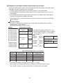
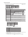
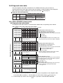
[1] Address order allocation
Assign the number of bytes of data in the input/output data table (data length) in the same order as
the node addresses are assigned to the slave stations.
1. Assign the number of bytes required by each slave station.
2. A slave station that does not have I/O message function is not assigned a data length.
3. Any slave station number (node address), that does not have hardware connected, is not
assigned a data length.
Allocation example
The allocation results from assigning data lengths "in the order in which vacant nodes are
occupied" are as follows:
Address *
1st byte (000000)
2nd byte (000001)
3rd byte (000002)
4th byte (000003)
5th byte (000004)
6th byte (000005)
7th byte (000006)
8th byte (000007)
9th byte (000010)
10th byte (000011)
11th byte (000012)
12th byte (000013)
to
512th byte (000777)
Input/output data table
Input
Node address 1
(slave station)
Output
Input
Node address 3
(slave station)
Output
* The addresses shown in parentheses ( )
are correct when the top address of the I/O
table is set to file address 000000(OCT) in file
number 1.
System memory
Node address 5
(slave station)
Input
Not used
#1600
to #1601
#1700
to #1701
000000 (OCT)
#1602
#1702
01(HEX)
#1603
#1703
00(HEX)
0
Node address
Required data length (bytes)
Setting value
I/O message
function
Yes
1
Assigned data length (bytes)
2 (1 input, 1 output)
1
2 (1 input, 1 output)
2
Not connected
3
6 (3 input, 3 output)
Yes
6 (3 input, 3 output)
4
0
No
0
5
3 (3 input, 0 output)
Yes
3 (3 input)
-
Module address
0
- The required number of bytes are assigned to the slaves at nodes 1, 3, and 5.
- Slave 2 (nothing connected) and slave 4 (doesn't have a I/O message function) are not
assigned any data length.
7-2
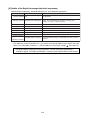
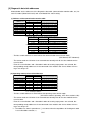
The scan list data table for this example will be as follows:
Address *
1st byte (000000)
2nd byte (000001)
3rd byte (000002)
4th byte (000003)
5th byte (000004)
6th byte (000005)
7th byte (000006)
8th byte (000007)
9th byte (000010)
Value (hexadecimal): Details (=> See page 7-9)
FF: This JW-50DN station (master)
Node
address 0
All zeroes
slave station with a Polling I/O
02: A
function
00: Not used
01: 1 byte (input data length)
01: 1 byte (output data length)
00: 1st byte
00:
(input data offset)
01: 2nd byte
00:
(output data offset)
00: Not connected
Node
address 1
Node
address 2
Node
address 3
Address *
ValueH: Details
* The addresses shown in parentheses ( ) are correct when
the top address of the scan list table is set to file address
000000(OCT) in file number 2.
Module address
7-3
Node
address 6
~
Node
address 5
505th byte (000770)
506th byte (000771)
507th byte (000772)
508th byte (000773)
509th byte (000774)
510th byte (000775)
511th byte (000776)
512th byte (000777)
All
zeroes
~
Node
address 4
49th byte (000060)
50th byte (000061)
51st byte (000062)
52nd byte (000063)
53rd byte (000064)
54th byte (000065)
55th byte (000066)
56th byte (000067)
~
10th byte (000011)
11th byte (000012)
12th byte (000013)
13th byte (000014)
14th byte (000015)
15th byte (000016)
16th byte (000017)
17th byte (000020)
18th byte (000021)
19th byte (000022)
20th byte (000023)
21st byte (000024) All zeroes
22nd byte (000025)
23rd byte (000026)
24th byte (000027)
slave station with a Polling I/O
25th byte (000030) 02: A
function
26th byte (000031) 00: Not used
27th byte (000032) 03: 3 bytes (input data length)
28th byte (000033) 03: 3 bytes (output data length)
29th byte (000034) 02: 3rd byte
30th byte (000035) 00:
(input data offset)
31st byte (000036) 05: 6th byte
32nd byte (000037) 00:
(output data offset)
slave station without a Polling I/O
33rd byte (000040) 01: A
function
34th byte (000041)
35th byte (000042)
36th byte (000043)
37th byte (000044) All zeroes
38th byte (000045)
39th byte (000046)
40th byte (000047)
slave station with a Polling I/O
41st byte (000050) 02: A
function
42nd byte (000051) 00: Not used
43rd byte (000052) 03: 3 bytes (input data length)
44th byte (000053) 00: 0 byte (output data length)
45th byte (000054) 08: 9th byte
46th byte (000055) 00:
(input data offset)
47th byte (000056) 0B: 12th byte
48th byte (000057) 00
(output data offset)
All
zeroes
Node
address 63
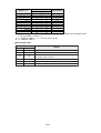
System memory
Setting value
#1614 to #1615 #1714 to #1715 000000
#1616
#1716
02(HEX)
#1617
#1717
00(HEX)
0
1
(OCT)
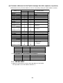
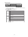
[2] Even number allocation
Assign the number of bytes of data in the input/output data table (data length) in the order that the
node addresses were assigned to each slave station.
1. Set the predetermined data length for slave stations to an even number of bytes.
If an individual slave station needs more than the default amount of data, the JW-50DN can be
used to assign a different data length in terms of multiples of the default data length.
2. The JW-50DN assigns the default data length to slave stations that do not have a I/O message
function.
3. The JW-50DN also assigns the default data length to slave station numbers (node addresses)
that do not have any hardware connected to them.
- Enter the data length (1 to 64 bytes) between 1 and 3 on the system memory of the JW-50DN.
See page 6-8.
Allocation example
The allocation results from assigning data lengths by "even number allocation" are as shown on
page 7-2, as follows.
- The default data length is 2 bytes.
Input/output data table
Address *
1st byte (000000)
2nd byte (000001)
3rd byte (000002)
4th byte (000003)
5th byte (000004)
6th byte (000005)
7th byte (000006)
8th byte (000007)
9th byte (000010)
10th byte (000011)
11th byte (000012)
12th byte (000013)
13th byte (000014)
14th byte (000015)
15th byte (000016)
16th byte (000017)
Node address 1
(slave station)
Input
Output
Node address 2
(not connected )
Not used
Input
Node address 3
(slave station)
* The addresses shown in parentheses ( ) are
correct when the top address of the I/O table is
set to file address 000000(OCT) in file number 1.
See page 7-2.
Node address 4
(slave station)
Node address 5
(slave station)
(When the default data length is set to 2 bytes)
1
Required data
length (bytes)
2 (1 input, 1 output)
2
Not connected
3
6 (3 input, 3 output)
Node address
Not used
~
17th byte (000020)
Node address 6
(not
connected )
18th
byte
(000021)
Output
to
131st
byte
(000202)
Not used
Node address 63
(not connected )
132nd byte (000203)
133rd
byte
(000204)
Input
Not used
to
Not used 512th byte (000777)
I/O message
function
Yes
Yes
Assigned data length
(bytes)
2 (1 input, 1 output)
2
6 (3 input, 3 output)
4
0
No
2
5
3 (3 input, 0 output)
Yes
4 (3 input, 1 not used)
- The needed data length (2 bytes) is assigned to slave station 1.
- Slave station 2 (not connected) and slave station 4 (does not have a I/O message
function) are assigned the default data length (2 bytes).
- Slave stations 3 and 5 need a larger number of bytes than the default data length.
(2 bytes).
Therefore, in these cases, a different data length is assigned which is a multiple of the
default data length (2 bytes).
- Slave station 3 needs 6 bytes and is assigned 6 bytes (2 x 3).
- Slave station 5 needs 3 bytes and is assigned 4 bytes (2 x 2).
7-4
Not used
The scan list data table for this example will be as follows:
Address * 1
1st byte (000000)
2nd byte (000001)
3rd byte (000002)
4th byte (000003)
5th byte (000004)
6th byte (000005)
7th byte (000006)
8th byte (000007)
Value (hexadecimal): Details (=> See page 79)
FF: This JW-50DN station (master)
Node
address 0
All zeroes
slave station with a Polling I/O
02: A
function
10th byte (000011) 00: Not used
11th byte (000012) 01: 1 byte (input data length)
12th byte (000013) 01: 1 byte (output data length)
13th byte (000014) 00: 1st byte
14th byte (000015) 00:
(input data offset)
15th byte (000016) 01: 2nd byte
16th byte (000017) 00:
(output data offset)
17th byte (000020) 00: Not connected
18th byte (000021) 00: Not used
19th byte (000022) 00: 0 byte (input data length)
20th byte (000023) 00: 0 byte (output data length)
21st byte (000024) 02: 3rd byte
22nd byte (000025) 00:
(input data offset)
23rd byte (000026) 02: 3rd byte
24th byte (000027) 00:
(output data offset)
slave station with a Polling I/O
25th byte (000030) 02: A
function
26th byte (000031) 00: Not used
27th byte (000032) 03: 3 bytes (input data length)
28th byte (000033) 03: 3 bytes (output data length)
29th byte (000034) 04: 5th byte
30th byte (000035) 00:
(input data offset)
31st byte (000036) 07: 8th byte
32nd byte (000037) 00:
(output data offset)
A slave station without a I/O
33rd byte (000040) 01: message function
34th byte (000041) 00: Not used
35th byte (000042) 00: 0 byte (input data length)
36th byte (000043) 00: 0 byte (output data length)
37th byte (000044) 0A: 11th byte
38th byte (000045) 00:
(input data offset)
39th byte (000046) 0A: 11th byte
40th byte (000047) 00:
(output data offset)
41st byte (000050) 02: A slave station with a Polling I/O
function
42nd byte (000051) 00: Not used
43rd byte (000052) 03: 3 bytes (input data length)
44th byte (000053) 00: 0 byte (output data length)
45th byte (000054) 0C: 13th byte
46th byte (000055) 00:
(input data offset)
47th byte (000056) 0F: 16th byte
48th byte (000057) 00:
(output data offset)
9th byte (000010)
Node
address 1
Node
address 2
Node
address 3
Address * 1
ValueH: Details
00
00
00
00
11 * 2
00
11 * 2
00
Node
address 6
~
~
Node
address 5
505th byte (000770)
506th byte (000771)
507th byte (000772)
508th byte (000773)
509th byte (000774)
510th byte (000775)
511th byte (000776)
512th byte (000777)
~
Node
address 4
49th byte (000060)
50th byte (000061)
51st byte (000062)
52nd byte (000063)
53rd byte (000064)
54th byte (000065)
55th byte (000066)
56th byte (000067)
00
00
00
00
83 * 2
00
83 * 2
00
Node
address 63
* 1: The addresses shown in parentheses ( ) are correct when the top address of the scan list table is
set to file address 000000(OCT) in file number 2.
See page 7-3.
* 2: The offset values are calculated by adding 2 bytes (default data length) to each address.
7-5
[3] Allocation in the order in which vacant nodes are occupied
Assign the number of bytes of data in the input/output data table (data length) in the order that the
node addresses were assigned to each slave station.
1. Assign the required data length to slave stations using the I/O message function.
2. The JW-50DN does not allocate any data length for slave stations that do not have a I/O message function.
3. The JW-50DN will allocate the default data length to any slave station number (node address)
that does not actually have hardware connected.
Enter the data length (1 to 64 bytes) between 1 and 3 on the system memory of the JW-50DN.
See page 6-8.
Allocation example
The results of "allocation in the order in which vacant nodes are occupied, "for the example
shown on page 7-2, are as follows.
- The default data length was set to 2 bytes.
Address *
Node address 2
(not connected )
Not
used
* The addresses shown in parentheses ( ) are
correct when the top address of the I/O table is
set to file address 000000(OCT) in file number 1.
See page 7-2.
Input
Node address 3
(slave)
14th byte
15th byte
Output 128th byte
129thbyte
130thbyte
Node address 5
(slave)
(000015)
Node address 6
(not connected )
(000016)
to
(000177) Node address 63
(not connected )
(000200)
(000201)
Not used
to
(000777)
Input
512th byte
(When the default data length is set to 2 bytes)
Node
address
1
2
3
4
5
Not used
~
1st byte (000000)
2nd byte (000001)
3rd byte (000002)
4th byte (000003)
5th byte (000004)
6th byte (000005)
7th byte (000006)
8th byte (000007)
9th byte (000010)
10th byte (000011)
11th byte (000012)
12th byte (000013)
13th byte (000014)
Input/output data table
Input
Node address 1
(slave)
Output
Required data
I/O message
length (bytes)
function
2 (1 input, 1 output)
Yes
Not connected
6 (3 input, 3 output)
Yes
0
No
3 (3 input, 0 output)
Yes
Assigned data
length (bytes)
2 (1 input, 1 output)
2
6 (3 input, 3 output)
0
3 (3 input)
- The default data length is assigned to slave stations 1, 3, and 5.
- Slave station 2 (no hardware connected) is assigned the default data length (2 bytes).
- Slave station 4 (without a I/O message function) is not allocated any data length.
7-6
Not used
The scan list data table for this example will be as follows:
Address * 1
1st byte (000000)
2nd byte (000001)
3rd byte (000002)
4th byte (000003)
5th byte (000004)
6th byte (000005)
7th byte (000006)
8th byte (000007)
Value (hexadecimal): Details (=> See page 7-9)
FF: This JW-50DN station (master)
Node
address 0
All zeroes
A slave station with a Polling
02: I/O
function
10th byte (000011) 00: Not used
11th byte (000012) 00: 1 byte (input data length)
12th byte (000013) 01: 1 byte (output data length)
13th byte (000014) 00: 1st byte
14th byte (000015) 00:
(input data offset)
15th byte (000016) 01: 2nd byte
16th byte (000017) 00:
(output data offset)
17th byte (000020) 00: Not connected
18th byte (000021) 00: Not used
19th byte (000022) 00: 0 byte (input data length)
20th byte (000023) 00: 0 byte (output data length)
21st byte (000024) 02: 3rd byte
22nd byte (000025) 00:
(input data offset)
23rd byte (000026) 02: 3rd byte
24th byte (000027) 00:
(output data offset)
A
slave
station with a Polling
25th byte (000030) 02: I/O function
26th byte (000031) 00: Not used
27th byte (000032) 03: 3 bytes (input data length)
28th byte (000033) 03: 3 bytes (output data length)
29th byte (000034) 04: 5th byte
30th byte (000035) 00:
(input data offset)
31st byte (000036) 07: 8th byte
32nd byte (000037) 00:
(output data offset)
A
slave
without a I/O
33rd byte (000040) 01: messagestation
function
34th byte (000041)
35th byte (000042)
36th byte (000043)
37th byte (000044) All zeroes
38th byte (000045)
39th byte (000046)
40th byte (000047)
A slave station with a Polling
41st byte (000050) 02: I/O
function
42nd byte (000051) 00: Not used
43rd byte (000052) 03: 3 bytes (input data length)
44th byte (000053) 00: 0 byte (output data length)
45th byte (000054) 0A: 11th byte
46th byte (000055) 00:
(input data offset)
47th byte (000056) 0D: 14th byte
48th byte (000057) 00:
(output data offset)
9th byte (000010)
Node
address 1
Node
address 2
Node
address 3
Address * 1
ValueH: Details
00
00
00
00
0F * 2
00
0F * 2
00
~
~
Node
address 5
505th byte (000770)
506th byte (000771)
507th byte (000772)
508th byte (000773)
509th byte (000774)
510th byte (000775)
511th byte (000776)
512th byte (000777)
00
00
00
00
81 * 2
00
81 * 2
00
Node
address 6
~
Node
address 4
49th byte (000060)
50th byte (000061)
51st byte (000062)
52nd byte (000063)
53rd byte (000064)
54th byte (000065)
55th byte (000066)
56th byte (000067)
Node
address 63
* 1 :The addresses shown in parentheses ( ) are correct when the top address of the scan list table is
set to file address 000000(OCT) in file number 2.
See page 7-3.
* 2 :The offset values are calculated by adding 2 bytes (default data length) to each address.
7-7
7-2 Editing the scan list
Before using the JW-50DN as a master mode for the first time, you will have to edit the scan list (to
allocate I/O data).
[1] Editing procedure
Shown below are the procedures used to edit the scan list.
Procedures
1 Switch the JW50H/70H/100H control module to the program mode.
Note: The scan list can be edited when the "Not protected: Switch 6-7 is OFF", even if the JW50DN is in operation mode. For safety, only edit the scan list in the program mode.
2 Turn OFF the power to the JW50H/70H/100H.
3 Change switch SW6-7 on the JW-50DN to "Protection OFF."
See page 6-5.
- If switch SW6-7 is set to the protected mode, the procedures below will not work.
4 Install the JW-50DN in the JW50H/70H/100H.
See chapter 4.
5 Connect any slave stations.
- Basically, all slave stations must be started.
See * 1 below.
6 Turn ON the power to the JW50H/70H/100H.
7 Press and hold the SCAN switch on the JW-50DN for at least 3 seconds.
- The JW-50DN will edit the scan list.
See * 2 below.
8 After the editing process is complete, turn OFF the power to the JW50H/70H/100H.
9 Remove the JW-50DN from the JW50H/70H/100H.
0 Set switch SW6-7 on the JW-50DN to the protected mode.
q Reinstall the JW-50DN in the JW50H/70H/100H.
w Turn ON the power to the JW50H/70H/100H.
e Put the JW50H/70H/100H control module in the operation mode.
* 1: Connecting the slave stations mentioned in step 5 above
- When "even number allocation" or "allocation in the order in which vacant nodes are occupied" is
selected for the I/O data allocation method, and some node addresses are not occupied by slave
stations, those node address will be assigned the default number of bytes. This will make operation
possible with only the connected slave stations.
When a slave station is connected at a vacant address, and if this station needs more than the default
number of bytes for I/O, the I/O addresses thereafter can be incremented by editing the next time a
scan list is created.
* 2: Scan list editing procedure mentioned in step 7
- When the JW-50DN is in the normal operation mode and you change the JW50H/70H/100H to the
operation mode, the JW-50DN will start I/O communication. However, when you press the SCAN
switch immediately after communication is started, the JW-50DN will start editing the scan list. This
may cause a malfunction. Therefore, we recommend that you change to the protected mode as
described in step 8 above.
7-8
[2] Scan list data table
Assign top address of the scan list data table (512 bytes) to the following system memory.
(
See page 6-7.)
Addresses in the scan list data table
Master Slave
○
No. of
bytes
512
一
Module No. switch setting
0
#1614 to #1617
(408 bytes)
1
#1714 to #1717
(320 bytes)
(○: Enable, ー: Disable)
Details of the scan list data table
Address * 1
1st byte (000000)
2nd byte (000001)
3rd byte (000002)
4th byte (000003)
5th byte
6th byte
7th byte
8th byte
9th byte
to
16th byte
17th byte
to
24th byte
|
|
|
505th byte
to
512th byte
(000004)
(000005)
(000006)
(000007)
(0000010)
to
(0000017)
(000020)
to
(000027)
|
|
|
(000770)
to
(000777)
Details
Slave information flag * 2
Not used
- Data length for the data which slave
Input data length
stations will send and receive in
Output data length Polling I/O messages.
Input data
offset
Output
data offset
- These indicate the byte mappings in the I/O
data table (page 7-1) that data will be sent
from or received into using I/O messages. * 4.
Node
address
0
* 3 information
Node address 1 information (same as node address 0)
Node address 2 information (same as node address 0)
|
|
|
Node address 63 information (same as node address 0)
* 1 : The addresses shown in parentheses ( ) are correct when the top address of the scan list table
is set to file address 000000(OCT) in file number 2.
System memory
Setting value
#1614 to #1615 #1714 to #1715 000000 (OCT)
#1616
#1716
02(HEX)
#1617
#1717
00(HEX)
0
1
Module address
* 2 : Slave information flag
Value(HEX)
00
01
02
04
FF
Details
Node not connected
Node connected, does not have a I/O message function
Node connected with a Polling I/O function
Node connected with a Bit Strobe.
JW-50DN's node address
* 3 : The data following the input data length becomes meaningful when the 1st byte of the slave
data flag is 02 or 04.
* 4 : The position of an address from the top byte is expressed by a byte + 1.
(Ex.: When the value is 0, it is the 1st byte. When the value is 2, it is the 3rd byte.)
7-9
Chapter 8: Explicit Message Function
This function is not needed when you use the I/O message function.
The JW-50DN can send a request for service to any device made by another manufacturer that uses the
Explicit message function defined in the DeviceNet specifications. (#1622, #1722 = 01(HEX)
See page 68.) This function uses the Explicit message data table (128 bytes for both request and response) in the PC
(JW50H/70H/100H).
- An Explicit message data table request issues an Explicit message defined by DeviceNet, and asks any
corresponding device to provide service.
- The Explicit message data table response stores the service data details from the slave station.
Set the top address of the Explicit message table to the following point in system memory.
See page 6-7.
Addresses of the Explicit message data table areas (requests and responses)
Master
○
Table
No. of
bytes
Requests
128
Responses
128
Slave
ー
Module No. switch setting
0
1
#1610 to #1613
#1710 to #1713
(Specify top address (Specify top address
and enable/disable) and enable/disable)
(○: Enable, ー: Disable)
[1] Details of the Explicit message data table (requests)
JW-50DN side reading flag, control module writing flag, and other parameters are described.
Address *
Parameter name
Details
1st byte (000000)
JW-50DN side reading
flag
When the JW-50DN has finished reading the contents
being sent, the data in memory is automatically inverted.
(Inverting data changes 00(H) + 01(H), and vise-versa.)
2nd byte (000001)
Control module
writing flag
When the data has been inverted, the JW-50DN will send a
request message to the slave station.
3rd byte (000002)
Status
The device status and response information are stored.
4th byte (000003)
TXID (transaction ID)
Assign an ID when creating a request.
5th byte (000004)
Size
Set the request data length.
6th byte (000005)
Reserved area
Use prohibited.
7th byte (000006)
MAC ID
Set a node address for the transaction object.
8th byte (000007)
Service code
Service code for the DeviceNet request.
9th byte (000010)
10th byte (000011)
Class ID
Assign a class ID to the Explicit message sending target.
11th byte (000012)
12th byte (000013)
Instance ID
Assign an instance ID to the Explicit message sending
target.
~
13th byte (000014)
Service data (106 bytes) Assign data that is defined by a service code.
118th byte (000165)
* The addresses shown in parentheses ( ) are correct when the top address of the Explicit message
table is set to file address 000000(OCT) in file number 1. (For the addresses of the other settings
See page 8-3.)
- For details about the Explicit message parameters, see the "DeviceNet specifications."
To obtain a copy of "DeviceNet specifications," contact an ODVA branch office in your country.
8-1
[2] Details of the Explicit message data table (responses)
Control module reading flag, JW-50DN writing flag etc. are provided for parameters.
Address *
Parameter name
Details
module reading
1st byte (000200) Control
flag
When reading the received data, the same data is written to
the JW-50DN.
2nd byte (000201) JW-50DN side writing flag
When the JW-50DN receives a response from a slave
station, the JW-50DN inverts the data. (Inverting data
changes 00(H) to 01(H), and vise-versa.)
3rd byte (000202) Status
The device status and response information are stored.
4th byte (000203) TXID (transaction ID)
Transaction ID of the response data.
5th byte (000204) Size
Response data length.
6th byte (000205) Reserved area
Use prohibited.
7th byte (000206) MAC ID
Node address that will be the target for the transaction.
~
8th byte (000207) Service code
Service code for the Device Net request.
9th byte (000210)
A received data message, as defined by the service code, is
Response data (110 bytes) returned.
118th byte (000365)
* The addresses shown in parentheses ( ) are correct when the top address of the Explicit message
table is set to file address 000000(OCT). (For the addresses of the other settings
See page 8-3.)
- For details about the Explicit message parameters, see the "DeviceNet specifications."
To obtain a copy of "DeviceNet specifications," contact an ODVA branch office in your country.
8-2
[3] Parameter addresses for the Explicit message data table (requests, responses)
Shown below are the parameter addresses that are selected by setting the module address switches.
Module address switch set value
Parameter name
0
1
(000000)
*1
*2
JW-50DN reading flag
(000001)
Control module writing flag
(000002)
Status
(000003)
TXID (transaction ID)
(000004)
Size
(000005)
Reserved area
(000006)
MAC ID
(000007)
Service code
(000010)
Class ID
(000011)
(000012)
Instance ID
(000013)
(000014)
Service data
(106 bytes)
∼
∼
118th byte (000165)
129th byte (000200)
130th byte (000201)
131st byte (000202)
132nd byte(000203)
133rd byte (000204)
134th byte (000205)
135th byte (000206)
136th byte (000207)
137th byte (000210)
*3
Control module read out flag
JW-50DN write flag
Status
TXID (transaction ID)
Size
Reserved area
MAC ID
Service code
*4
∼
∼
Response data
(110 bytes)
246th byte (000365)
*1: Enter top address to system memory #1610 to #1613.
System memory Item
Setting range etc.
#1610 to #1611 File address
000000 to 177777(OCT)
#1612
File number
00 to 07(HEX)
#1613
Enable/disable 00(HEX): Enable, 01(HEX) : Disable
*2: Enter top address to system memory #1710 to #1713.
System memory Item
Setting range etc.
000000 to 177777(OCT)
#1710 to #1711 File address
00 to 07(HEX)
#1712
Fine number
#1713
Enable/disable 00(HEX): Enable, 01(HEX): Disable
*3: "*1+128th byte" address.
*4: "*2+128th byte" address.
*5: Addresses in parenthesis are ones when top address of the Explicit
message table is set to "file address 000000(OCT)."
8-3
Response
1st byte
2nd byte
3rd byte
4th byte
5th byte
6th byte
7th byte
8th byte
9th byte
10th byte
11th byte
12th byte
13th byte
Request
Address (*5)
[4] Example
Shown below is an example of reading the vendor ID of the identified object in a slave station (node
address 1.)
(Top address of Explicit message table: File address 000000(OCT))
Explicit message data table
(requests)
Address
(OCT)
Parameter name
side reading
000000 JW-50DN
flag
module writing
000001 Control
flag
000002 Status
Explicit message data table
(responses)
Address
Value(HEX)
00(01)
(OCT)
Parameter name
Control module reading
34 000200 flag
Value(HEX)
00(01)
7
00(01)
6
00
side writing
000201 JW-50DN
flag
000202 Status
000003 TXID
00
000203 TXID
00
000004 Size
06
000204 Size
02
000005 Reserved area
00
000205 Reserved area
00
000006 MAC ID
00
000206 MAC ID
01
000007 Service code
00
000207 Service code
8E
000210
68
000010
000011
000012
000013
000014
000015
Class ID
Instant ID
Service data
00(01)
01
2
1
000211
00
Response data
01
00
01
00
When Sharp's vendor ID is returned:
104 (decimal) = 68 (hex.)
01
00
Request table
1 Enter the values above in the request table (000002 to 000015(OCT)).
2 Reverse the write flag (000001(OCT)) . (00 -> 01:*)
3 When the write flag (00001(OCT)) and read flag (000000(OCT)) are not the same, the JW-50DN
starts reading the details of the transaction.
4 When the read process is complete, the JW-50DN automatically reverses the read flag
(000000(OCT)) (00 -> 01:*), so that the read flag will be same value as the write flag.
The JW-50DN sends a request message to a slave module.
Response table
5 When the JW-50DN receives a response corresponding to the request above from a slave
module, or if a time out occurs, the JW-50DN writes data to the transaction block in the response
table.
- The JW-50DN stores the response data from a slave module in the transaction block, starting at
address 000202(OCT). In practice, the slave module vender ID104(DCM) for MAC ID01 is stored
with the service data.
6 The values of the write flag (000201(OCT)) in the response is reversed.
7 Until the write flag (000200(OCT)) (00 -> 01:*) is reversed, the details of the transaction block
are not allowed to change. To issue messages consecutively, the [read/write/reverse] flag should
be reversed.
* Reverse
The initial status of each flag is 000. When receiving a response after sending a request, the flag
changes to 01. Then the flag changes back to 00 again, and so on.
8-4
5
Chapter 9: Communication Timing
This chapter describes the communication between the control module (JW50H/70H/100H), the JW-50DN
(master), and the slave stations.
To exchange data between the JW-50DN and the JW50H/70H/100H control module, the JW-50DN uses
optional processing by the JW50H/70H/100H.
(Control module processing)
Hardware check
(JW-50DN: Process of master station)
Input/output processing
Data exchange using
data exchange memory
Data exchange memory
Optional processing
User program
processing
I/O message
communication
The JW-50DN receives responses from all slave stations. If not, after a communication time out, it will
complete one I/O message communication cycle, and exchange data with the JW50H/70H/100H control
module.
- The time-out time is the normal time required after the JW-50DN completes sending commands to all of the
slave stations, until it receives responses from all of the slave stations. The actual communication time-out
period is determined by the setting of Switch SW6-8 on the JW-50DN and the number of slave stations
connected.
See page 6-9.
The division of the communication timing between the I/O message communication time and the operation
time of the JW50H/70H/100H is as follows.
[1] When the I/O message communication time is shorter than the JW50H/70H/100H
cycle operation time
Communication cycle: Asynchronous/synchronous
JW50H/70H/100H
Optional processing
Operation of the
control module
Optional processing
User program/Input and output processing
Operation of the
JW-50DN
User program/Input and output processing
Waiting time
Waiting time
Response
Command
I/O message communication
Response
Command
1
2
63
1
Slave stations (maximum 63 nodes)
9-1
2
63
Slave stations (maximum 63 nodes)
Optional processing
[2] When the I/O message communication time is longer than the JW50H/70H/100H
cycle operation time
(1) Communication cycle: Asynchronous
JW50H/70H/100H
Optional processing
Operation of the
control module
User program/input
and output processing
Optional processing
User program/input
and output processing
User program/input
and output processing
User program/input
and output processing
Waiting
time
Operation of the
JW-50DN
Response
Command
I/O message communication
1
2
Command
63
1
Slave stations (maximum 63 nodes)
2
Slave stations (maximum 63 nodes)
(2) Communication cycle: Synchronous
JW50H/70H/100H
Optional processing
Operation of the
control module
User program/input
and output processing
Waiting time
Optional processing
User program/input
and output processing
Optional processing
Waiting time
Operation of the
JW-50DN
Command
Response
I/O message communication
1
2
63
Command
Response
1
Slave stations (maximum 63 nodes)
2
63
Slave stations (maximum 63 nodes)
Note: The synchronous calculation operation is only possible with one module, including other
communication modules (JW-10CM, JW-20CM). Therefore, be careful because using multiple modules in the synchronous mode may not permit synchronous operation.
9-2
Chapter 10: Error Handling
When an error occurs during communication with the JW-50DN, check the error details by referring to the
display lamps and the diagnostic data table. Then take the appropriate action.
10-1 Display lamp
When an error occurs on a node (master and slave station), the error code and the node address will
be displayed on the JW-50DN display panel (S0 to S7).
JW-50DN
S0
S1
S2
S3
S4
S5
S6
S7
MS
NS
SD
RD
FT
PT
Error code 1 (turns on for 1 second)
Goes OFF (for 0.1 seconds)
( ) Times in parenthesis are display on or off times.
The node address of the slave station where a code 1 error has occurred (turns on for 1 second).
Goes OFF (for 0.3 seconds)
Error code 2 (turns on for 1 second)
Goes OFF (for 0.1 seconds)
The node address of the slave station where a code 2 error has occurred (turns on for 1 second).
Goes OFF (for 0.3 seconds)
Goes OFF (for 0.3 seconds)
Error code N (turns on for 1 second)
Goes OFF (for 0.1 seconds)
The node address of the slave station where a code N error has occurred (turns on for 1 second).
- There is no priority in the display of errors. The JW-50DN displays the errors in the order in which
they occur.
- If the same error occurs on multiple nodes, such as a communication error, only the lowest node
address will be displayed.
- For information about the error code display and details, as well as the node addresses, see the
following pages.
10-1
[1] Error code
(1) Error code display
The JW-50DN displays error codes using lights S0 to S7 on the display panel.
S0 to S7 lamp status (● : Lit, ○ : Off)
Error code
S 7 S 6 S 5 S 4 S 3 S 2 S 1 S 0 (hexadecimal)
●
●
○
●
○
○
●
○
D2
●
●
○
●
○
●
○
●
D5
●
●
○
●
○
●
●
○
D6
●
●
○
●
●
○
○
●
D9
●
●
●
○
○
○
○
○
E0
●
●
●
●
○
○
○
○
F0
●
●
●
●
○
○
○
●
F1
●
●
●
●
○
○
●
○
F2
●
●
●
●
○
○
●
●
F3
●
●
●
●
○
●
○
○
F4
●
●
●
●
○
●
○
●
F5
●
●
●
●
○
●
●
●
F7
●
●
●
●
●
○
○
○
F8
●
●
●
●
●
○
○
●
F9
●
●
●
●
●
○
●
○
FA
●
●
●
●
●
○
●
●
FB
(2) Error details
The error code details and actions are as follows.
Indication lamp
S0 to S7
(error code)
MS/NS/FT
D2
D5
MS: Keeps the
current status
NS: Red lamp
blinks
MS: Green
lamp blinks
NS: Goes OFF
To the next page
D6
Communication
operation
Error details
The I/O area of
Configur- one slave station
ation
exceeds input
error
127 bytes, output
127 bytes
- Dose not retry
connection for
error slave
station.
- Dose not
communicate
- There is no
with all the slave
slave data table
station.
at all.
- The slave does
Verificati- not exist.
on
error
The slave's I/O
data size does
not match the
scan list register
details.
D9
- A slave time
out has
occurred 6
times in a row
Commun- while waiting
ication
for a response.
error
- A fragmentation protocol
error has
occurred 3
times.
E0
Network
power
source Communication
power dose not
error
(Sending supply normally.
error)
- Retry connection
for error slave
station.
- Communicate
with normal slave
station.
Waiting power
supply from
network power
supply.
Master status *1
Treatment
the slave node
D4 turns ON * 2 Reset
addresses.
D16 and
D3 turn ON * 2
- Check whether the slaves
are properly connected.
- Recreate the scan list after
checking the slave
connections and node
assignments.
After checking the number of
I/O bytes used by the slaves,
recreate the scan list.
D16 and
D2 turn ON * 2
D16 and
D5 turn ON
Check the following:
- Make sure the
communication speed of the
master station and slave
stations are the same.
- Make sure there are no
disconnected or loose
cables.
- Make sure there is not too
much electrical noise.
- Make sure the cable lengths
(trunk and branches) are
appropriate.
- Make sure the terminating
resistances are connected
to both ends and only to the
ends.
Check wiring of network
power supply and network
cable.
* 1 : Master status
See page 10-9, 10-11.
* 2 : D17 will turn ON when the JW-50DN is connected to more than 1 slave
station. (If the master station detects a problem or is unable to establish
connection with all slave stations, D17 will turn OFF.)
10-2
Display lamp
MS/NS/FT
F0
A node
address has
been used
twice
The master station
node address has
been assigned to
another node.
Detected a
Bus OFF
The JW-50DN Bus
OFF status is active
(communication was
stopped due to
frequent data errors).
MS: Keeps
the current
status
NS: Red
lamp lights
F1
F2
MS: Red
lamp blinks
NS: Goes
OFF
MS: Red
lamp lights
NS: Goes
OFF
F3
Operation Master
of
status
JW-50DN
*
Error details
S7 to S0
(error node)
Node
address
error
Communica- Some of the switches
on the JW-50DN are
tion speed
set incorrectly.
error
F4
Module No.
error
F5
System
memory
setting error
F7
Scan list
data error
F8
Serial No.
error
Treatment
Check the other node
addresses.
Eliminate the duplicated
node address and restart the
master module
(JW-50DN).
Check the following:
- Make sure the
communication speed of
the master station and
D16
and D1 slave stations are the
same.
turn
ON. - Make sure there are no
disconnected or loose
cables.
- Make sure there is not too
much electrical noise.
- Make sure the cable
lengths (trunk and
branches) are appropriate.
- Make sure the terminating
resistances are connected
both ends and only to the
ends.
Check the node address
switch.
Operation
stopped
Check the SW6-5, 6 switch
settings.
Check the Module No. switch
settings.
D16
and D0
turn Check the set values of the
ON. system memory.
Some settings in the
JW-50DN system
memory are out of
the specified range.
The EEPROM has
a memory error.
- Unable to read or
write the scan list
parameters since
no data table
exists on the
master module.
F9
RAM error
An error occurred
during a RAM check of
the master module.
FA
ROMSUM
error
An error occurred
during a ROM check of
the master module.
FB
DPRAM
error
An error occurred
during a common RAM
check of the master
module.
MS: Keeps
the current
status
NS: Keeps
the current
status
—
Watchdog
timer error
A watchdog timer error
occurred on the master
station.
FT: Lights
—
Watchdog timer error on the JW50DN (Hardware error on the JW50DN).
Recreate the scan list and
recreate the data table in the
master module (JW-50DN).
Or, replace the JW-50DN.
—
Operation
stopped
Replace the JW-50DN.
Operation
stopped
* Master status
10-3
—
—
See page 10-9, 10-11.
[2] Display of node addresses
The JW-50DN displays node addresses using the S0 to S7 lamps on the display panel.
S0 to S7 lamp status (● : Lit, ○ : Off)
S7 S6 S5 S4 S3 S2 S1 S0
○
○
○ ○
○
○
○
○
○
○
○ ○
○
○
○
●
○
○
○ ○
○
○
●
○
○
○
○ ○
○
○
●
●
○
○
○ ○
○
●
○
○
○
○
○ ○
○
●
○
●
○
○
○ ○
○
●
●
○
○
○
○ ○
○
●
●
●
○
○
○ ○
●
○
○
○
○
○
○ ○
●
○
○
●
○
○
○ ●
○
○
○
○
○
○
○ ●
○
○
○
●
○
○
○ ●
○
○
●
○
○
○
○ ●
○
○
●
●
○
○
○ ●
○
●
○
○
○
○
○ ●
○
●
○
●
○
○
○ ●
○
●
●
○
○
○
○ ●
○
●
●
●
○
○
○ ●
●
○
○
○
○
○
○ ●
●
○
○
●
○
○
● ○
○
○
○
○
○
○
● ○
○
○
○
●
○
○
● ○
○
○
●
○
○
○
● ○
○
○
●
●
○
○
● ○
○
●
○
○
○
○
● ○
○
●
○
●
○
○
● ○
○
●
●
○
○
○
● ○
○
●
●
●
○
○
● ○
●
○
○
○
○
○
● ○
●
○
○
●
○
○
● ●
○
○
○
○
○
○
● ●
○
○
○
●
○
○
● ●
○
○
●
○
○
○
● ●
○
○
●
●
○
○
● ●
○
●
○
○
○
○
● ●
○
●
○
●
○
○
● ●
○
●
●
○
○
○
● ●
○
●
●
●
○
○
● ●
●
○
○
○
○
○
● ●
●
○
○
●
○
●
○ ○
○
○
○
○
○
●
○ ○
○
○
○
●
○
●
○ ○
○
○
●
○
○
●
○ ○
○
○
●
●
○
●
○ ○
○
●
○
○
○
●
○ ○
○
●
○
●
Node
address
(decimal)
0
1
2
3
4
5
6
7
8
9
10
11
12
13
14
15
16
17
18
19
20
21
22
23
24
25
26
27
28
29
30
31
32
33
34
35
36
37
38
39
40
41
42
43
44
45
S0 to S7 lamp status (● : Lit, ○ : Off)
S7 S6 S5 S4 S3 S2 S1 S0
○
●
○ ○
○
●
●
○
○
●
○ ○
○
●
●
●
○
●
○ ○
●
○
○
○
○
●
○ ○
●
○
○
●
○
●
○ ●
○
○
○
○
○
●
○ ●
○
○
○
●
○
●
○ ●
○
○
●
○
○
●
○ ●
○
○
●
●
○
●
○ ●
○
●
○
○
○
●
○ ●
○
●
○
●
○
●
○ ●
○
●
●
○
○
●
○ ●
○
●
●
●
○
●
○ ●
●
○
○
○
○
●
○ ●
●
○
○
●
○
●
● ○
○
○
○
○
○
●
● ○
○
○
○
●
○
●
● ○
○
○
●
○
○
●
● ○
○
○
●
●
10-4
Node
address
(decimal)
46
47
48
49
50
51
52
53
54
55
56
57
58
59
60
61
62
63
10-2 Diagnostic data table
Using the diagnostic data table created on the PC (JW50H/70H/100H), you can check the
communication status of the nodes (master and slave stations). Assign the address of the diagnostic
table (256 bytes) using the module No. switch on the JW-50DN.
See page 6-7.
Diagnostic data table addresses
Module No. switch setting value
Master Slave No. of bytes
○
○
0
1
#1604
to
#1607
#1704
to
#1707
Master: 256
(Specify top address (Specify top address
Slave: 128 and enable/disable) and enable/disable)
(○: Enable)
10-2-1 When JW-50DN is master mode
[1] Diagnostic data table details
The diagnostic data table contains a communication monitor table, an operating status monitor
table, a device status table, and master status details.
Address * 1
1st byte (000000)
2nd byte (000001)
3rd byte (000002)
4th byte (000003)
5th byte (000004)
6th byte (000005)
7th byte (000006)
8th byte (000007)
9th byte (000010)
D7
D6 D5 D4 D3 D2 D1 D0 ← Bit number
7
6
5
4
3
2
1
0
15
14
13
12
11
10
9
8
23
22
21
20
19
18
17
16
31
30
29
28
27
26
25
24
39
38
37
36
35
34
33
32
47
46
45
44
43
42
41
40
55
54
53
52
51
50
49
48
63
62
61
60
59
58
57
56
Diagnostic data (256 bytes)
Reserved area * 2
32nd byte (000037) D7 D6 D5 D4 D3 D2 D1 D0
7
6
5
4
3
2
1
0
33rd byte (000040)
8
34th byte (000041) 15 14 13 12 11 10 9
35th byte (000042) 23 22 21 20 19 18 17 16
36th byte (000043) 31 30 29 28 27 26 25 24
37th byte (000044) 39 38 37 36 35 34 33 32
38th byte (000045) 47 46 45 44 43 42 41 40
39th byte (000046) 55 54 53 52 51 50 49 48
40th byte (000047) 63 62 61 60 59 58 57 56
41st byte (000050)
Reserved area * 2
64th byte (000077)
65th byte (000100)
66th byte (000101)
127th byte (000176)
128th byte (000177)
129th byte (000200)
130th byte (000201)
Communication monitor table (8 bytes)
- The node addresses are numbered 0 to 63.
The communication status of each node is
indicated by turning the bits in these 8 bytes ON and OFF.
ON: Normal
OFF: Abnormal
=> See the next page.
- A bit representing the JW-50DN (master module) status
will turn OFF when any of the slave stations is abnormal.
Operating status monitor table (8 bytes)
- The node addresses are numbered 0 to 63.
The operating status of each node is
indicated by turning the bits in these 8 bytes ON and OFF.
ON: The slave station is operating
OFF: The slave station is idle.
=> See the next page.
- For details about the operating status of slave stations,
see the specifications for each slave station.
Node 0
Node 1
Node 62
Node 63
D7 D6 D5 D4 D3 D2 D1 D0
D17 D16 D15 D14 D13 D12 D11 D10
131st byte (000202)
Reserved area * 2
Device status table (64 bytes)
- The status of the slave station devices can be monitored
by keeping track of the device status codes assigned to
each node address. 00(H) is normal.
=> See page 10-7.
Master status (2 bytes)
- The error information and operating status of the master
station is indicated by turning bits ON and OFF.
=> See page 10-9.
210th byte (000321)
211th byte (000322)
Vender information (46 bytes)
=> Page 10-10.
256th byte (000377)
* 1 : The addresses shown in parentheses ( ) are correct when the top address of the diagnosis table
is set to file address 000000(OCT). (For the addresses of the other settings
See page 6-7.)
* 2 : Do not change any values in the reserved area. If you do, the JW-50DN will malfunction.
10-5
[2] Diagnostic data table addresses
Shown below are the addresses of the diagnostic data table (communication monitor table, etc.) for
each PC model (JW50H/70H/100H) and each Module No. switch setting.
(1) Address of the communication monitor table
Node address (Bit)
Module address switch set value
0
1
D7 D6 D5 D4 D3 D2 D1 D0
*2
*3
7 6 5 4 3 2 1 0
1st byte (000000)
15 14 13 12 11 10 9 8
2nd byte (000001)
23 22 21 20 19 18 17 16
3rd byte (000002)
31 30 29 28 27 26 25 24
4th byte (000003)
39 38 37 36 35 34 33 32
5th byte (000004)
47 46 45 44 43 42 41 40
6th byte (000005)
55 54 53 52 51 50 49 48
7th byte (000006)
63 62 61 60 59 58 57 56
8th byte (000007)
Address (*1)
*2: Enter top address to system memory #1604 to #1607.
System memory Item
Setting range etc.
#1604 to #1605 File address
000000 to 177777(OCT)
#1606
File number
00 to 07(HEX)
#1607
Enable/disable 00(HEX): Enable, 01(HEX) : Disable
*3: Enter top address to system memory #1704 to #1707.
System memory Item
Setting range etc.
000000 to 177777(OCT)
#1704 to #1705 File address
00 to 07(HEX)
#1706
Fine number
#1707
Enable/disable 00(HEX): Enable, 01(HEX): Disable
- The bits at node addresses 0 to 63 indicate the communication status of each node.
(ON: Normal, OFF: Abnormal)
- The master node turns ON when it can communicate normally with all the slave modules on the
scan list table.
- Even the "even allocation" and " allocation in order of securing empty notes" are selected, bits
corresponding to node addresses of "not connected slave module" and "slaves without I/O message" are always OFF.
(2) Operating status monitor table addresses
Node address (Bit)
Module address switch set value
0
1
D7 D6 D5 D4 D3 D2 D1 D0
*4
*5
7 6 5 4 3 2 1 0
(000040)
15 14 13 12 11 10 9 8
(000041)
23 22 21 20 19 18 17 16
(000042)
31 30 29 28 27 26 25 24
(000043)
39 38 37 36 35 34 33 32
(000044)
47 46 45 44 43 42 41 40
(000045)
55 54 53 52 51 50 49 48
(000046)
63 62 61 60 59 58 57 56
(000047)
Address (*1)
33rd byte
34th byte
35th byte
36th byte
37th byte
38th byte
39th byte
40th byte
*4: "*2+32nd byte" address.
*5: "*3+32nd byte" address.
- The bits at node addresses 0 to 63 indicate the operating status of each node.
(ON: Slave station is operating, OFF: Slave station is idle)
- The master node turns ON when it can communicate normally with all the slave modules on the
scan list table.
- Even the "even allocation" and " allocation in order of securing empty notes" are selected, bits
corresponding to node addresses of "not connected slave module" and "slaves without I/O message" are always OFF.
* 1 : The addresses shown in parentheses ( ) are correct when the top address of the diagnosis table
is set to file address 000000(OCT).
10-6
(3) Device status table addresses
When an error occurs on a slave station device, a device status code (next page) will be stored at
the following addresses. (When the communication is normal, 00(HEX) will be stored.)
Module address switch set value
Node address
0
1
*6
*7
(000100)
0
(000101)
1
(000102)
2
(000103)
3
(000104)
4
(000105)
5
(000106)
6
(000107)
7
(000110)
8
(000111)
9
(000112)
10
(000113)
11
(000114)
12
(000111)
13
(000116)
14
(000117)
15
(000120)
16
(000121)
17
(000122)
18
(000123)
19
(000124)
20
(000125)
21
(000126)
22
(000127)
23
(000130)
24
(000131)
25
(000132)
26
(000133)
27
(000134)
28
(000135)
29
(000136)
30
(000137)
31
(000140)
32
(000141)
33
(000142)
34
(000143)
35
(000144)
36
(000145)
37
(000146)
38
(000147)
39
(000150)
40
(000151)
41
(000152)
42
(000153)
43
(000154)
44
(000155)
45
(000156)
46
(000157)
47
(000160)
48
(000161)
49
(000162)
50
(000163)
51
(000164)
52
Address (*1)
65th byte
66th byte
67th byte
68th byte
69th byte
70th byte
71st byte
72nd byte
73rd byte
74th byte
75th byte
76th byte
77th byte
78th byte
79th byte
80th byte
81st byte
82nd byte
83rd byte
84th byte
85th byte
86th byte
87th byte
88th byte
89th byte
90th byte
91st byte
92nd byte
93rd byte
94th byte
95th byte
96th byte
97th byte
98th byte
99th byte
100th byte
101st byte
102nd byte
103rd byte
104th byte
105th byte
106th byte
107th byte
108th byte
109th byte
110th byte
111th byte
112th byte
113th byte
114th byte
115th byte
116th byte
117th byte
* 1 : The addresses shown in parentheses ( ) are correct when the top address of the diagnosis
table is set to file address 000000(OCT)."
*6: "*2+64th byte" address. (*2, *3: See the previous page)
*7: "*3+64th byte" address.
10-7
Module address switch set value
Node address
0
1
*8
*9
(000165)
53
(000166)
54
(000167)
55
(000170)
56
(000171)
57
(000172)
58
(000173)
59
(000174)
60
(000175)
61
(000176)
62
(000177)
63
Address (*1)
118th byte
119th byte
120th byte
121st byte
122nd byte
123rd byte
124th byte
125th byte
126th byte
127th byte
128th byte
* 1 : The addresses shown in parentheses ( ) are correct when the top address of the diagnosis table
is set to file address 000000(OCT)."
*8: "*6+53rd byte" address.
(*6, *7: See the previous page)
*9: "*7+53rd byte" address.
Device status code
Device status code
Details
Decimal Hexadecimal
0
0
The slave station is normal or it is not in the scan list.
72
48
The slave station device has stopped communication.
73
49
Identification of the slave station device does not match
the value in the scan list.
77
78
86
4D
4E
56
The data size is different from the setting.
The slave station device does not return a response.
The slave station device is idle.
10-8
(4) Master status address
Displays error information and operating status by turning bits ON and OFF.
Module address switch set value
Diagnostic details
0
1
Error information (D0 to D7)
*10
*11
129th byte (000200)
Operation status (D10 to D17)
(000201)
130th byte
Address (*1)
*12
* 1 : The addresses shown in parentheses ( ) are correct when the top address of the diagnosis
table is set to file address 000000(OCT)."
*10: "*2+128th byte" address. (*2, *3: See page 10-6)
*11: "*3+128th byte" address.
*12: Details of the D0 to D7, and D10 to D17 bits.
D0
D1
D2
D3
Error
information D4
D5
D6
D7
D10
D11
D12
D13
Operation D14
status
D15
D16
Incorrect switch settings, EEPROM error
Duplicated assignment of a node address. Bus OFF is detected.
Communication error
Verification error
Configuration error
Sending error
Reserved area
Currently creating scan list
Currently writing serial numbers
Reserved area
Disabled scan list (protected mode)
Message communication enable flag
Error is currently occurring
Currently performing I/O message communication.
D17 - Tunes ON when communicating with "any of slaves" on the
scan list table.
10-9
(5) Vender data address
The vender data is used when SHARP provides services to JW-50DN users. Do not use the vender
data in your applications.
Address (*1)
Vender data
Storage value (data details)
211th byte (000322) Vender ID
212th byte (000323) (2 byte)
104(DCM)
213th byte (000324) Device Type
214th byte (000345) (2 byte)
012(DCM)
215th byte (000326) Product Code
216th byte (000327) (2 byte)
217th byte (000330) Revision
218th byte (000331) (2 byte)
000(DCM)
000(DCM)
002(DCM)
000(DCM)
01(HEX)
02(HEX)
Vender ID code
(Sharp = 104)
Device type (JW-50DN = 012
<- communication adapter
Product code
(JW-50DN = 002)
Software version (The values
left is when S1.2).
219th byte (000332)
220th byte (000333) Serial Number
221st byte (000334) (4 byte)
222nd byte (000335)
Serial No. □□△△21○○○○(DCM)*2
(Written when manufacturing the JW50DN)
223rd byte (000336)
4A(HEX) : J
224th byte (000337)
57(HEX) : W
225th byte (000340)
35(HEX) : 5
226th byte (000341)
30(HEX) : 0
227th byte (000342) Product Name
228th byte (000343) (32 byte)
44(HEX) : D
229th byte (000344)
00(HEX)
:
:
:
:
254th byte (000375)
00(HEX)
"JW-50DN" of ASCII code.
4E(HEX) : N
All 00(HEX)
255th byte (000376)
Scan list
When scan list is established, 01(HEX) (if
establishing flag not 00(HEX)).
256th byte (000377)
Serial No.
When serial No. is established, 01(HEX) (if
establishing flag not 00(HEX)).
*1 : The addresses shown in parentheses ( ) are correct when the top address of the diagnosis table
is set to file address 000000(OCT).
*2: Serial number. □□△△21○○○○(DCM)
□□: Year manufactured (lower two digits of Western year: "01" for 2001
△△: Month manufactured ("01" for January, --- "12" for December)
21: Model code (JW-50DN is "21")
○○○○: Serial number (reset each month)
Ex.: A unit first manufactured in July 2001: 0107210001(DCM)
10-10
10-2-2 When the JW-50DN is used in the slave mode
Diagnostic table (256 bytes)
The diagnosis tables contain a communications monitor table, an operating status monitor
table, a device status table, a master status table, and vender data.
Address * 1
1st byte (000000)
2nd byte (000001)
3rd byte (000002)
4th byte (000003)
5th byte (000004)
6th byte (000005)
7th byte (000006)
8th byte (000007)
9th byte (000010)
D7
D6 D5 D4 D3 D2 D1 D0 ← Bit number
Communication monitor table (1 bit: D0)
OFF(D7 to D1)
- The communication status of slave station is
OFF(D7 to D1)
indicated by turning the bits in these ON and OFF.
Device status table (1-byte)
ON: Normal
Reserved area * 2
OFF: Abnormal
D7 D6 D5 D4 D3 D2 D1 D0
D17 D16 D15 D14 D13 D12 D11 D10
Operating status monitor table (1 bit: D0)
- The operating status of slave station is
indicated by turning the bits in these ON and OFF.
Reserved area * 2
Vender information (120 bytes)
=> Page 10-12.
ON: The JW-50DN is operating
OFF: The JW-50DN is idle.
128th byte (000177)
The status of the slave station devices can be monitored
by keeping track of the device status codes assigned to
each node address. 00(H) is normal.
=> See (1) below.
Master status (2 bytes)
- The error information and operating status of the master
station is indicated by turning bits ON and OFF.
=> See (2) below.
*1 : The addresses shown in parentheses ( ) are correct when the top address of the I/O table is set to
file address 000000(OCT).
*2: Do not modify the numbers in the reserved areas. That may cause the machine to malfunction.
(1) Device status code
Device status code
Details
Decimal Hexadecimal
0
0
The slave station is normal or it is not in the scan list.
72
48
The slave station device has stopped communication.
73
49
Identification of the slave station device does not match
the value in the scan list.
77
78
86
4D
4E
56
The data size is different from the setting.
The slave station device does not return a response.
The slave station device is idle.
(2) Master status address (D0 to D17: 2 bytes)
D0
D1
D2
D3
Error
information D4
D5
D6
D7
D10
D11
D12
Operation D13
status
D14
D15
D16
D17
Incorrect switch settings, EEPROM error
Duplicated assignment of a node address. Bus OFF is detected.
Communication error
Verification error
Configuration error
Sending error
Reserved area
Reserved area
Currently writing serial numbers
Reserved area
Message communication enable flag
An error is occurred, and the I/O message stops communication.
Currently performing I/O message communication.
10-11
(3) Vender data address
The vender data is used when SHARP provides services to JW-50DN users. Do not use the vender
data in your applications.
Address (*1)
Vender
information
Storage value (data details)
9th byte (000010)
10th byte (000011)
Vender ID
(2 byte)
104(DCM)
11th byte (000012)
12th byte (000013)
Device Type
(2 byte)
012(DCM)
13th byte (000014)
14th byte (000015)
Product Code
(2 byte)
15th byte (000016)
16th byte (000017)
Revision
(2 byte)
17th byte (000020)
18th byte (000021)
19th byte (000022)
20th byte (000023)
Serial Number
(4 byte)
000(DCM)
000(DCM)
002(DCM)
000(DCM)
01(HEX)
02(HEX)
4A(HEX) : J
22nd byte (000025)
57(HEX) : W
23rd byte (000026)
35(HEX) : 5
24th byte (000027)
30(HEX) : 0
26th byte (000031)
Product Name
(32 byte)
Device type (JW-50DN =
012 <- communication
adapter
Product code
(JW-50DN = 002)
Software version (The
values left is when S1.2).
Serial No. □□△△21○○○○(DCM) *2
(Written when manufacturing the JW50DN)
21st byte (000024)
25th byte (000030)
Vender ID code
(Sharp = 104)
JW-50DN" of ASCII code.
44(HEX) : D
4E(HEX) : N
27th byte (000032)
00(HEX)
:
:
:
:
52nd byte (000063)
00(HEX)
All 00(HEX)
53rd byte (000064)
:
Reserved area
- Do not change the numeric values.
Otherwise, malfunction will occur.
126th byte (000175)
127th byte (000176)
Scan list
When scan list is established, 01(HEX) (if
establishing flag not 00(HEX)).
128th byte (000177)
Serial No.
When serial No. is established, 01(HEX)
establishing flag (if not 00(HEX)).
*1 : The addresses shown in parentheses ( ) are correct when the top address of the diagnosis table
is set to file address 000000(OCT).
*2: Serial number. □□△△21○○○○(DCM)
□□: Year manufactured (lower two digits of Western year: "01" for 2001
△△: Month manufactured ("01" for January, --- "12" for December)
21: Model code (JW-50DN is "21")
○○○○: Serial number (reset each month)
Ex.: A unit first manufactured in July 2001: 0107210001(DCM)
10-12
10-3 JW-50DN status when the control module has stopped operation
or error has occurred
When the JW50H/70H/100H control module is in the program mode (operation has stopped), the
JW-50DN sends out status information that the JW-50DN is in idle. (The display lamps and master
status are the same as normal communication.)
Communication operation
Input data Transfer data received from an input slave to the control module.
When used in the
The data sent to an output slave module depends on the system
master mode
Output data
memory settings. *
Input data Always sends idle data to the master module.
When used in the
Transfer data received from the maser module to the control
slave mode
Output data
module.
* Output to slave modules (when the control module is stopped)
is determined by the value (00, 01(HEX)) in system memory addresses
#1630 (module address = 0), and #1730 (module address = 1).
00(HEX): Restore (master module sends idle data)
01(HEX): Clear (master module sends 00(HEX) data)
When receiving idle data
When the JW-50DN receives idle data, the data sent to the control module is always the same.
10-13
Chapter 11: Specifications
(1) General specifications
Item
Applicable PLC
Insulation resistance
Withstand voltage
Storage temperature
Ambient operating
temperature
Ambient humidity
Vibration resistance
Shock resistance
Specification
JW-50CUH, JW-70CUH, JWControl module
100CUH
Number of modules that can be Maximum two
installed
Optional interface (no occupation of
I/O points)
Interface with a control module
- An optional cable is needed to
connect to a rack panel.
10 Megohms or more with 500 VDC Meger
1500 VAC, 50/60 Hz, for one minute
-20 to +70° C
0 to +55° C
35 to 90%RH (non condensing)
Equivalent to JIS C 0911.
Oscillation distance: 0.15 mm (10 to 58 Hz), 9.8 m/s2 (58 to 150 Hz)
(2 hours each for X, Y, and Z directions.)
Equivalent to JIS C0912.
98 m/s2 (3 times each in the X, Y, and Z directions)
Communication power 11 to 25 VDC (50 mA max./JW-50DN)
voltage
Internal power
150 mA max. (5 VDC)
consumption
Atmosphere
No corrosive gas
Weight
Approximately 320 g
Accessories
One instruction manual
(2) Communication specifications
Item
Communication protocol
Basic operation mode
Number of nodes
connectable
Number of I/O points
Communication speed
Specification
Conforms to the DeviceNet protocol
Master mode, slave mode.
Maximum of 63 nodes for one master station.
4,096 points (512 bytes) in an input/output data table.
Selectable: 125 kbps, 250 kbps, or 500 kbps.
Communication speeds
125 k bit/s 250 k bit/s 500 k bit/s
Trunk length using a thick cable
500m
250m
100m
Communication
Trunk length using a thin cable
100m
100m
100m
distance (max.)
Maximum branch length
6m
6m
6m
Total branch length
156m
78m
39m
I/O
message
function
(Polling
I/O
function,
Bit
Strobe
function),
Explicit
Communication services message function
Specialized cable (5 lines: 2 signal lines, 2 power lines, 1 shield line)
Communication carrier - Thick cable: For trunk lines
- Thin cable: For trunk or branch lines
Select the method used for I/O data mapping in the scan list edit mode
Data table allocation
from "allocation in address order," "even number allocation," or
method
"allocation in the order in which vacant nodes are occupied."
11-1
(3) External dimension drawings
JW-50DN
S0
S1
S2
S3
S4
S5
S6
S7
MS
NS
Basic rack panel
SD
RD
FT
PT
NODE ADRS.
456
901
78
23
×10
456
901
78
23
×1
UNIT ADRS.
456
901
78
250
23
SCAN
(Unit: mm)
TERMINATOR
ON
OFF
33.5
105
110
11-2
5