1
Distributed by
Any reference to Raytheon or
RTN in this manual should be
interpreted as Raymarine.
The names Raytheon and RTN
are owned by the
Raytheon Company.
NAV398GPS/IL>RAI\l
GPSlLORAN
OPERATION MANUAL
i
Table of Contents
Page
SECTION 1 INTRODUCTION
1 .O General
1.1 About This Manual
l-l
l-l
SECTION 2 INSTALLATION
2.0 General
2.1 Unpacking and Inspection
2.1.1 Equipment Supplied
2-l
2-l
2-l
2.2 Display Installation
2.2.1 Choosing a Location
2.2.2 Mounting the NAV Unit
2.2.3 Flush Mounting
2-2
2-2
2-3
2-3
2.3 Electrical Connections
2.3.1 Power Input
2.3.2 Sensor Connections
2.3.3 Interface to External Navaids
2.3.4 Ground Connection
2-4
2-5
2-5
2-6
2-7
SECTION 3 OPERATION
3.1 General
3.2 The Keyboard
3.3 Basic Operations
3.3.1 Turning the Unit ON/OFF
3.3.2 Contrast/Backlighting Level
3.3.3 Auto Start-up
3.3.4 Selecting Loran/GPS Mode
3-1
3-1
3-3
3-3
3-3
3-3
3-4
3.4 Initializing Sensors
3.4.1 Estimated Latitude
3.4.2 Estimated Longitude
3.4.3’The Status Page
3-5
3-6
3-6
3-7
3.5 Main Display Modes
3.5.1 Position Display Mode
3.5.2 Customizing Display Modes
3.5.3 Navigation Display Mode
3.5.4 CD1 Display Mode
3.5.5 Plot Display Mode
3.5.6 Simulator Mode
3.5.7 Display Mode Operations
3.5.7.1 Saving Events
3.5.7.2 GOT0 Destinations
3-8
3-8
3-11
3-l 1
3-12
3-13
3-16
3-16
3-16
3-17
3.6 Entering Waypoints
3.6.1 General Waypoint Information
3.6.2 Waypoint Directory
3.6.3 Naming Waypoints
3.6.4..Storing Waypoints
3.6.4.1 Entry by L/L
3.6.4.2 Entry by TDs
3.6.4.3 Entry by Bearing/Distance
3-19
3-19
3-19
3-21
3-22
3-22
3-23
3-24
3-24
3-25
3-25
3-25
3.6.5 Waypoint List Operations
3.6.5.1 Selecting Waypoints
3.6.5.2 Editing Waypoints
3.6.5.3 SF Operations
_ _ . . -. .
3.7 Setting Alarms
3.7.1 Arrival Alarm
3.7.2 Anchor Alarm
3.7.3 Off-Course Alarm
3-27
3-27
3-28
3-29
3.8 Man-Overboard Mode
3-29
3.9 Route Plans
3.9.1 Make a Route
3.9.2 Following Route Plans
3.9.3 Editing Route Plans
3.9.4 Erasing Route Plans
3-30
3-31
3-32
3-33
3-34
3.10 The Menu Key
3.10.1 Main Menu Directory
3.10.2 Signal Status Pages
3-35
3-35
3-36
--
-.
.
.-
.
. - .-_ . . . - .
_ __. __ _ _*.--_
-. ..,. .-.--.---
SECTION 1
INTRODUCTION
1 .O General
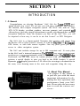
Congratulations on selecting Raytheons’ NAV 398 for Loran-C/GPS navigation aboard your vessel. We are sure you will enjoy using this ultra modern,
full function, and compact navigation system. The NAV 398, with its’ large
STN LCD display, excellant graphics, on-sceen prompts, and oversized soft
silicon keys, provide simple operations to guide you through the various
navigation functions. From the moment you turn on the NAV 398, you will
be surprised at how easy it can be to use this Loran-C or GPS Navigator.
The NAV 398 is a feature-packed Navigator that operates with inputs from
the Raynav 508 or 508A Loran-C sensors, or with the Raystar 108 8-Channel
GPS sensor, or with both sensors together. One key press gives you quick
access to either navigation system.
The NAV unit includes storage for up to 500 waypoints and 10 route plans
in the NAV unit’s internal memories. The[m[ key stores your present
position as a waypoint instantly with a single key press. The[E[(ManOverboard) key not only stores an instant position with one key press, but
activates a special display to steer you back to the MOB location. A special
Dynamic CD1 display provides a 3-D effect for steering to destinations in
the route; even showing turns in the route and waypoints along the way.
1.1 About This Manual
The purpose of this manual is
to provide you with the most
important information for obtaining the best operation and
performance from your NAV
unit. Please take the necessary
time to read the various sections.
INTRODUCTION
l-l
In the event that you are using a Loran-C Navigator for the first time, please
refer to the Raynav 508/508~ Loran-C Sensor instruction manual for basic
loran information. The Introduction section of the 508 manual includes a
listing of common Loran C Terminology used with loran.
If your NAV398 is using the RAYSTAR 108 GPS Sensor, the Raystar 108
instruction manual includes a general description of the GPS system which
may also be helpful. The Raystar 108 GPS sensor is compatible with
Raytheon’s Differential Beacon Receiver. If you have added the DGPS
Receiver to your system, a simple explanation of the US Coast Guard’s
DGPS system is included in that manual for your reference.
Section 2 of this manual contains important information concerning the
installation of your new NAV unit. Although the typical installation might
seem straightforward and simple, we highly recommend that this section be
read completely and the guidelines for installation be closely followed to
assure a more trouble free and efficient operation of your new unit.
Section 3 covers the Operations of the NAV 398 and is intended to get you
thoroughly familiar with the unit’s controls and display formats. The NAV
398 uses many on-screen prompts to help guide you through operations and
logical key operations, which should be easy to remember.
The best way to learn about your NAV 398 is to dive right in. You can’t
damage the unit by randomly pressing the keys, so don’t be afraid to
experiment. If at any time the results appear confusing, just press the pl
key and start again.
Section 4 contains technical information concerning some basic care and
maintenance for your unit. In the event that the unit should ever require
repairs, it is recommended that these services be provided by an Authorized
Raytheon repair facility or by the Raytheon Factory Service Center.
Before proceeding to install this unit, please take a few moments to fill out
the warranty registration card located behind the front cover of this manual.
You must return this card to Raytheon Marine Company to assure the
registration of the warranty for your NAV unit. The postage is prepaid if the
card is mailed within the USA.
INTRODUCTION
1-2
S E C T I O N 2
INSTALLATION
2.0 General
Although your NAV 398 is designed to the highest levels of quality and
performance, it can best attain those standards only when it has been properly
installed. This section provides the user with practical guidelines to assist in
the planning and the installation of the NAV 398 aboard your vessel.
2.1 Unpacking and Inspection
Use care when unpacking the unit from its shipping carton to prevent
damage to the contents. It is also good practice to save the carton and interior
packing material until the unit has been installed on the vessel. The original
packing material should be used in the unlikely event that it is necessary to
return the unit to the factory.
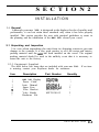
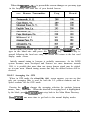
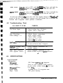
2.1.1 Equipment Supplied
The table below lists items that are included with your NAV 398. If an item
is missing, contact your Raytheon dealer for assistance.
Item
1
2
3
4
5
6
7
Description
Part Number
NAV 398 Display
G263746- 1
CQC-4737
G263746-5
MF60NR-2A
MTD005707
MPTG30012
Power Cable
Instr. Manual
Spare Fuse
Yoke Bracket
Yoke Knobs
Hardware Kit
Quantity
1
1
1
2
1
2
1
INSTALLATION 2-l
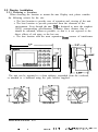
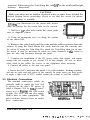
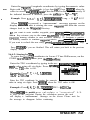
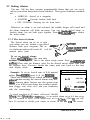
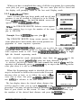
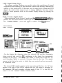
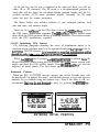
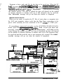
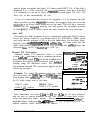
2.2 Display Installation
2.2.1 Choosing a Location
When choosing the location to mount the NAV Display unit, please consider
the following criteria for the site:
l The best location to provide ease of operation and viewing of the unit.
l The best location to provide protection from the elements of the
environment. Even though the NAV 398 is designed to meet the toughest
USCG waterproofing specifications, common sense dictates that it
should be mounted, whenever possible, so that it is not exposed to the
direct effects of salt spray or the hot sun.
l The best location with the most separation from sources of interference.
lIIizl
NAV396GPSLORAN
The unit can be mounted to a chart tabletop, suspended from the overhead,
or attached to a bulkhead using the yoke bracket supplied.
6
TABLE TOP
6
BULKHEAD
OVERHEAD
INSTALLATION 2-2
-__
_
-
.
.
..-w...
~
.
-
_
_
.__
_.
..-:
-_*..-.
,v
”
-1..-
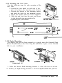
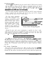
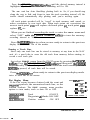
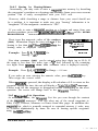
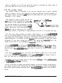
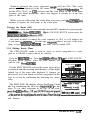
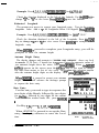
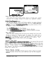
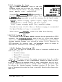
2.2.2 Mounting the NAV Unit
Use the following steps for yoke mounting of the
NAV Unit:
1. Loosen the yoke knobs on each side of the
unit. and remove the mounting yoke bracket.
2. Position the bracket to the mounting surface
and mark the holes for the mounting screws.
3. Mount the bracket with the screws supplied.
4. Slide the unit back into the yoke and secure
in the desired viewing position by
tightening the yoke knobs.
IN THE YOKE BRACKET
4 HOLES .25”
I
,
8.07”?
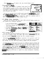
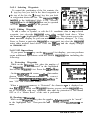
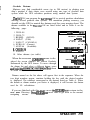
2.2.3 Flush Mounting
The display can also be flush mounted in a console using the Optional Flush
Mount Kit (M95990) or the Trim Ring Kit (M95995) to give a more finished
look to your installation.
TRIM RING
CONSOLE MOUNTINQ
&
M95995
,+=+A
-__.-.
dFLUSH MOUNT KIT
1. Select the desired flush mounting location. A clear, flat area of at least
9” wide by 5” high having at least 5” of clear depth behind the panel is
INSTALLATION 23
required. When using the Trim Ring Kit, add 3/4” to the width and height
clearance dimensions.
CAUTION
Make sure there are no hidden electrical wires or other items behind the
desired location before proceeding. Check to see that free access for mounting and cabling is available.
2.Using the dimensions for the cutout hole shown,
draw the pattern for the cutout hole on the console.
3. Drill two l/2” pilot holes inside the cutout guide
area at diagonal corners.
4. Using an appropriate saw, cut along the outside
of the cutout line.
5. Remove the yoke knobs and the yoke and the rubber spacers from the
cabinet. If using the Flush Mount Kit verify that the unit fits correctly into
the cutout. If using the Trim Ring Kit, attach the Trim Ring, then test fit into
the cutout. It may be necessary to notch out some clearance in the cutout to
pass the trim ring hardware through the panel.
7. Complete the installation of the DC power cable, data output, and sensor
wiring into the console as per section 2.4 of this chapter. Be sure to allow
some slack in the cables for service to the equipment when necessary.
8. Connect all cables to the unit rear panel.
9. Insert the NAV unit into the panel. Use a flat washer, locking washer,
and nut on each stud and secure to the console. In some cases you may prefer
to apply a light coat of RTV sealant around the cutout to seal the console.
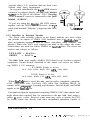
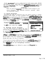
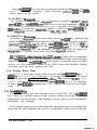
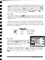
2.3 Electrical Connections
The standard connections which are
normally made to enable the NAV 398
to operate are the ship’s DC power, to
either a Raynav 508 or 508A Loran-C
sensor or to a Raystar 108 GPS sensor
or both. The NAV unit can also supply
NMEA data to other equipments. The
next sections discuss how to make
these connections.
LO
NMEAj!EATALK
INSTALLATION 2-4
_
._
,.
__
.
- .
-. _.j___-
_..,
.-
.-j
--,-
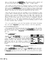
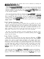
2.3.1 Power Input
The NAV 398 is intended for use on vessels with 12 VDC power systems
and can operate as long as the DC supply is maintained between 10 and 16
volts. The DC power system can be “negative” ground or have both positive
and negative supply lines “floating” above ground. The NAV 398 is not
11
intended for use on pas itiv,a” pround ve&
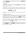
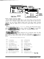
A 6 foot cable assembly containing wiring for the DC power and Data
Output is supplied with your display unit and in many cases will be adequate
to reach near the source of the 12 VDC power.
For best noise immunity
from other shipboard electronics, if possible, avoid
grouping the power connections on the same circuit
breaker with radar, radio, or
echo sounder power leads.
The NAV unit’s wiring
should be kept separate as
much as possible from other
devices.
DATA IN +
DATA OUT+
DATA OUT-
-12VDC
FUSE
RED +WD C
BROWN DATA IN -
Power Cable Wiring Diagram
Although the NAV unit’s power consumption is typically less than 5 watts,
if the power leads need to be extended more than 10 feet, the wire size of the
leads should be increased accordingly to minimize line losses. For cable runs
of 20 - 35 feet #12 AWG wire is recommended.
1 OBSERVE PROPER POLARITY! 1
The RED wire should be connected to the POSITIVE (+) sauce terminal;
the BLACK wire should be connected to the NEGATIVE (-) source
terminal If the power leads are accidentally reversed, the in-line fuse will
blow. If this happens, recheck the polarity of the connections with a voltmeter
(VOM) and, if necessary, reverse the leads for proper connection. Replace
the fuse.
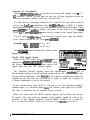
2.3.2 Sensor Connections
The sensor units used with the NAV 398 normally obtain their 12VDC
operating power input from the NAV unit and, when the NAV unit has been
turned ON, the sensors can then proceed to locate and track signals and
INSTALLATION 2-5
provide ship’s L/L position data on their own
without other input requirements.
In a typical installation, the 6-pin GPS sensor
connector is plugged directly into the jack labeled
“GPS” on the rear of the cabinet. The 5 Pin plug
of the Loran-C sensor is connected to the jack
labeled “LORAN”.
‘SZ
zz
If you are using the Raystar 108 GPS sensor
together with the DGPS Beacon Receiver, the “Y”
cable lead marked “Display” plugs into the GPS
jack.
2.3.3 Interface to External Navaids
The Power cable assembly (shown in the figure) includes two wires which
can provide an output of NMEA 0183 formatted data or SeaT&data for
other navigational equipment such as radars, auto-pilots, video sounders, and
plotters. Since the NAV unit outputs one data or the other, the same
connections are used for either NMEA or SeaTalk data. The wires are
marked and colored as follows:
YELLOW = DATA+
GREEN
= DATA The NAV 398 may supply NMEA 0183 data for up to three external
equipments. Navaid devices connected to this output can receive the following NMEA 0 183 sentences:
If LORAN Sensor is in use:
GLL, GTD, RMA, RMB, VTG, APA, APB, BWC.
If GPS Sensor is in use:
GLL, RMC, RMB, VTG, APA, APB, HSC, BWC.
When SeaTalk data is used, the NAV unit provides: magnetic variation,
COG, Cross-Track error, Lat./Long, GPS status data (including HDOP, fix
status), SOG, waypoint #, bearing, and distance, Arrival alarm, and MOB
signals to the SeaTalk bus.
External navigation equipment requiring NMEA 0183 data inputs normally obtain their required data via connection to the NAV 398 data output (
yellow & green ) wires. However, some users may wish to operate the GPS
(or Loran) sensor unit directly with other navigational equipment capable of
INSTALLATION 2-6
. .
_
_
.
_
_
_
-
.
.
,
~
___._...
_./
,I
---I-”7.”
accepting position data in the NMEA format. Please refer to the Raystar 108
or Raynav 508/508A instruction manuals for details on making this type of
interconnection.
Data Input
One feature of the NAV398 is to transfer the waypoint and route memory
contents of the internal memory to external computer files and to re-load the
memory from the computer.
Downloading of files occurs through the Data Output connections (Green
and Yellow wires). To Upload files into the NAV unit the Data Input wires
of the power cable assembly should be used. Make connections as follows:
DATAIN + = WHITE
DATA IN - = BROWN
The data Input must be in the NMEA 0 183 format using the WPL and RTE
sentences.
2.3.4 Ground Connection
One important need in any installation is to obtain the cleanest, noise-free
signals possible, for measuring and calculating your position. Part of this
requirement can be met by assuring a proper connection from your NAV unit
to the ship’s ground system. The ground system provides both a completion
of the signal path for the sensor and a drain for noise sources.
There are two separate wires labeled “GROUND” in the cable assembly.
Both the WHITE and BROWN wires should be connected to the nearest
connection point of the ship’s Rl? ground system.
Normally, on a steel hull boat, a good clean connection to the ship’s hull
makes a sufficient ground. On Fiberglas or wood hull vessels, connection to
a ground plate or to the engine block or other bonded groundwork should
provide acceptable grounding.
INSTALLATION 2-7
N 34v4. 714'
w 118" 35.236'
I 123'm
DTG
11.7nm
093'm
Sffi
10.9kt
-
I
!
\
-
NAV 1
3
N
34O14.714'
w 118" 35.236'
) POS 2
b-l
l
’
0
N 34Ol4.714'
w 118" 35.236'
N 35%. 452 ,
w115v5.223
MAIN DISPLAY MODES - NAV 398
INSTALLATION 2-8
. _. _ . ..._._,_ ,. -. _I . ..“. ~. a- -.w.--
SECTION3
OPERATION
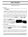
3.1 General
This chapter provides instructions for the operation of your new NAV 398
LCD NAVigator unit.
We think you will find the operation of the NAV 398 to be easy and
straightforward. The approach to take in becoming familiar with it’s operation is one of relaxed confidence. The unit is quite “user friendly” and relies
on screen prompting to guide you through the operations and set-up menus.
As you progress through the operating section, take time to practice each
function of your NAV398. Study the illustrations and repeat operations, if
necessary, until you have become comfortable and confident. Time spent in
becoming familiar with the unit will strengthen your knowledge, confidence,
and skill in using this full-featured NAVigator where it counts....afloat.
Thank you for selecting one of
Raytheon’s fine NAVigation products.
Great care and effort has been put into
providing you with a useful, attractive _
design. We are sure it will provide
many years of valuable NAVigation
data and trouble free operation.
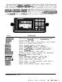
3.2 The Keyboard
The NAV 398 is designed for simple
operation, but if you should ever become confused over which display you
are on or, if you get lost while performing various operations or entries,usually pressing the -1
will always
key return you to the Position display
or the familiar Main menu.
One other item to remember about the keyboard is that a “valid” or correct
key press is confirmed by a single audio “beep” tone, while if an invalid or
wrong key is pressed, a series of multiple “beeps” will be heard. If this
happens, just check the screen again and pick the proper key operation.
OPERATION 3-1
The keyboard consists of 15 silicon rubber keys. Some of the keys carry
dual labels such as(ormkeys and are normally used to enter the
main operations of the NAV unit. The numeric operation of the key is used
once vou have entered the main oueration. Notice that some keys such as
1-1 and/morJMENUJ have only one label and perform only one
operation when depressed. When Menus are on screen, th$%%& IGoTo/7)
and thdE[ keys are softkeys used to activate selections on the menus.
.
I
KEY
rAkARMf9 1
PURPOSE
Turns power On/Off; activates ContrastILite menu .
Accepts data for entry;
Reverts to Main menu or POS display; resets numeric
values to 0; silences audio beeper.
Selects Position displays; selects digit 1.
Selects NAVigation displays; selectsdigit 2.
Selects a waypoint as a destination;selects digit 3.
Selects Waypoint entry function; selects digit 4.
Selects Route functions; selects digit 5.
Memorizes ship’s present position into designated
Waypoint memory; selects digit 6.
Selects destination waypoints; selects digit 7.
Selects Plot Mode display; selects digit 8.
Selects Alarm menu; selects digit 9.
Selects Loran C or GPS operations; selects digit 0.
Selects menu operations.
Selects Man-Overboard special alarm function.
OPERATION 3-2
.
___._*
--
.-
_,_~..
,-.
_._--
.-
.
.
_.
-c_.
.-
I
“---.-.
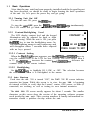
3.3
Basic Operations
Now that the NAV unit has been properly installed and the keypad layout
has been described, we should be ready to begin learning the basic operations
of the unit. So, let’s press the power key and get going!
3.3.1 Turning Unit On/ Off
To turn the unit ON, press themlkey.
To turn the unit OFF, press the /pwRp<ey andmqkeys simultaneously.
The LCD screen will go blank and the unit will be OFF.
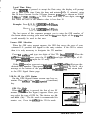
3.3.2 Contrast/Backlighting Level
The LCD display contrast level and the keypad
illumination may be adjusted for dusk or night
use and viewing. While the unit is ON, just press
them1 key to turn the backlighting menu On.
The Backlighting menu is only temporary and
will disappear when 7 seconds have elapsed
with no keys pressed.
+
CONTRAST 11
+
m HI LO LITE I,
PRESS CLEAR TO EXIT
3.3.2.1 Contrast Setting
When the BackLight menu appears, use thelwpT/4[and[T keys to
vary the contrast level of the LCD for best viewing. The level ranges from 0
to 15. The/eikey increases the contrast level;llkey decreases the
contrast level, as the arrows indicate.
3.3.2.2 Backlighting
Use thelc/uolkey to highlight HI, LOW, or OFF. The selection becomes
the active choice when it is backlighted in the menus.
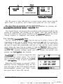
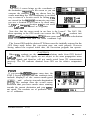
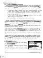
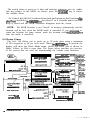
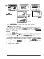
3.3.3 Auto Start-up
Each time the NAV 398 is turned “ON”, the NAV 398 ID screen indicates
operation has begun. While this screen is in view, the NAV 398 is beginning
an internal self-test to verify that the Loran-C sensor, GPS sensor, or both (if
connected) are working, as well as testing its own internal memories.
The NAV 398 ID screen usually appears for about 3 seconds. The smaller
characters on this screen show the version of the operating software program
used inside the NAV unit. This version number is handy information to
remember should a problem develop within the unit.
OPERATION 3-3
I
l.“,T..
10 H
-se
NWV 9PB
II
II
MRSON
NAV398
L”
‘&WON 1.0
-4
ROM
OK
RAM
OK
SENSOR OK
NOW TESTING
II
I
1
To SIONAL SYAYU.9 (IF NOT lMCNlN0)
To FMlYlON DlSFiAY IF TRACK,,,O.
The ID screen is then followed by a second screen which advises that the
SELF TEST is in process, and a third screen prints the SELF TEST results .
anytime by pressing the
The Signal Status screen provides a readout or the progress made by the
sensors in acquisition and tracking of the signals. Once full signal lock-on
has been achieved, the screen switches to the Position display, the Auto
Startup sequence is completed, and normal operation is underway.
3.3.4 Selecting Loran/GPS Mode
One key feature of the NAV 3% is that the unit can be either a loran or GPS
depending on the type of sensor that is connected, .or both, if a sensor for
each system is attached. Normally, if only one sensor is used, the unit detects
the type of sensor and automatically puts the NAV unit into the correct system
mode during the Auto Start-up program. If both the RayNAV 508/A Loran-C
and Raystar 108 GPS sensors are connected, .each system will always be
operating and normally tracking signals and either system can provide your
position and NAVigation data instantly.
TheI-key is used to toggle the unit
between the two system sensors. The systems
can be changed anytime you are on the PMtion, NAVigation, CDI, or PLOT modes.
When the GPS mode is selected, “GPS”
characters become illuminated along the bottom left edge of the LCD display and the
latitude/longitude position and ship’s course
and speed data is then GPS derived.
OPERATION 3-4
.
.
_;I ._.,.. . . . - .c - _._.,.. - .-.. A. _- .-. * .-_ ___- ,__ _ -.*-.-T-T.--
If the Differential Beacon Receiver is connected and tracking the beacon
signal “DGPS” is indicated in the message window. The latitude/longitude
readouts will include the differential corrections for greater accuracy.
When the Loran-C mode is selected, the “LORAN” characters will be
illuminated along in the message window of the display and the L/L position
and ship’s course and speed data is then Loran-C derived.
When both GPS and Loran sensors are connected, the NAV unit always
selects the sensor that was “last used” when the power is turned ON. If its
the very first time the unit is used and both sensors are connected, the GPS
is always selected as the priority system.
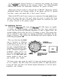
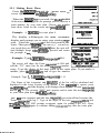
3.4 Initializing Sensors
Although the R~YNAV 508 Loran and Raystar 108 GPS sensors are capable
of finding the latitude/longitude position once they have been powered up,
at the very first power-up following installation or after a Master Reset, the
position finding process may take up to 30 minutes or more. This startup time
can be reduced to some degree by entering initialization information into the
sensor’s memory. The process for initializing each sensor appears in the
following paragraphs. The very first time the NAV
unit is operated, or following
a Master reset of the unit, the
screen will prompt you to enter your “estimated latitude”
coordinate followed by entry
of the “estimated longitude”
coordinate., Once you’ve entered this information into the
sensors via the NAV 398, the
sensors should be able to find
your location more rapidly.
The loran sensor only needs the initial L/L input and should typically lock-in
in 3 to 5 minutes. The GPS sensor also needs the initial L/L input and prefers
to have the Date and Time and Antenna height information as well for quick
acquisition and tracking.
OPERATION 3-5
The sensors always store the Lat/Lon position in memory. The next time
you use the NAV unit, the only thing you’ll have to do is just turn it “ON”.
In a few minutes your position will be displayed.
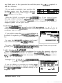
3.4.1 Estimated Latitude
With the "ESTIMATED POSITION" screen displayed, enter the latitude of
your position, using six digits. It is a good idea to enter your position to within
one degree of latitude. When the numbers are correct. nress(.
I
ESTIMATED POSITION
I
1
95. QQ'
WQQQ' QQ.QQ'
I
N 42’ Q5 QQ’ WJ’
- PUS&
N 42’
THENPRESSENTER
ESTIMATED POSITION
i
THEN PRESS ENTER
WQz1’ 14.5Q’
ENTERING INITIAL POSITION
If you’re new to navigation terminology, please refer to the Globe figure
on the previous page for verifying that the coordinate to be entered is truly
your latitude.
Check to see that the direction symbol “N” is correctly indicated to the left
of your latitude entry on the screen. If “S” is displayed, press thelN/Sbof?key
to change the symbol to “N”. Press -1 when the direction is correct.
Example: Press 4,2,0,5,0,0, I-J-[, for N 42’ 05.00’
Ifvou make a mistake in entering your estimated latitude, press theIkey and start the entry again. When the entry is correct, press -ito
accept the entry.
DEGREES
r ~MINIJTES
3.4.2 Estimated Loneitude
When-1 is iressed to finish your latitude
entry, the message on the display screen will
W 071’ 25.10+~aom=
changeto "ENTJZRYOLJRLONGITUDE~~.
Asbefore,
How to read a Lat/Long
enter your estimated longitude numeric value, this
time using seven digits-with an accuracy within
OPERATION 3-6
one degree of longitude. For longitudes of less than 100 degrees, begin the
entry with “0”.
After you press the mjey, check to see that the direction symbol “W”
is correctly indicated to the left of your longitude entry. If “E” is displayed,
to change
press the \r/wl
softkey the symbol to fgW'T or vice versa. If the
direction is correct, pres@CKJ.
Example: 0,7,1,1,4,5,0, mJ=lfor W 71’ 14.50’
If you make any mistakes while entering your longitude, press the-1
key and retype the entry. Then press([to complete the estimated
position entry.
When-1 is pressed to finish your longitude entry, the estimated
LAT/LON entry is complete and the display will return to the Auto Start-up
sequence at the Status page for sensor in use.
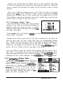
3.4.3 The Status Page
The STATUS screens show the condition of
the acquisition and tracking of signals for the
sensor in use.
I
SIGNALSTATUS
LORAN
1
EST +
In normal tracking operation for loran, the
flA@
GRI chain and secondary signals received are
ECD #
indicated in the status box. The most important
information are the status numbers to the right
PRESS CLEAR TO EXIT
of the SNR characters. These numbers show the
progress of the acquisition program towards signal lock-on. When 8’s are
indicated for the Master and selected Secondaries, the loran is “Locked-on”
and tracking the loran signals. At that point the screen automatically will
I
switch to the Position screen and navigation is available.
In normal tracking operation for GPS, there
is only ONE important indicator indicating
that the GPS is “Locked-on” and tracking the
satellite signals. That indicator is when the
satellite ID number becomes a reversed
“Block” character. When four or more signals
are in this state, the screen will switch to the
Position screen and navigation is now available.
PRESS CLEAR TO EXIT
OPERATION 3-7
More information on the Status and signal tracking screens appears later in
this chapter.
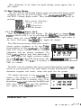
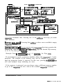
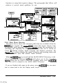
3.5 Main Display Modes
The NAV 398 has FOUR Main Display modes used most often during normal
navigation. They are the POS (Position), NAV (NAVigation), CD1 Graphic ,
and PLOT Tracking display modes. These modes can be selected directly by
pressing:
[ml
for the POS mode displays
I=[
for the NAV screens
f o r t h e CD1 d i s p l a y s
m[
)pLoT/FII for the Plot screens
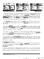
3.5.1 The POSition Display Mode
There are FIVE different POS displays. The POS display is changed from
POSl to POS2, POS 3, etc. by pressing the Im[key. The POS screen
age number in the lower right corner of
always shows the selected
the screen. Each press of
key toggles the displays.
The POS screens always show your vessel’s
present position coordinates in the large 7-segment readouts of either Lat/Lon or loran TDs.
Each POS screen combines different navigation
information with the position coordinates. The
POS Lat/Lon display may look differently if
you have selected the higher resolution readouts
for your Lat/Lon in the GPS Setup menu. The
NAV 398 can show GPS L/L to a resolution of
0.001 of a minute.
N 34O14.714'
w 118" 35.236'
The POS 1 screen combines the most essential information together onscreen of your position in the large digits, bearing and distance to the
destination waypoint, and vessels’ course and speed over the ground.
The number and name of your waypoint destination is also displayed, as well as the selected
route plan number that is currently active. If no
destination waypoint is selected, the BRG and
DTG values will be blank, and “NO DESTINATION” appears in the waypoint data bar.
OPERATION 3-8
.
__.
.__
.,
.
,.._
._
.--..-,-x-.
-
I
I
Along the bottom row, the sensor “in use” is indicated in the highlighted
block. If the Raynav 508 is used, “LORAN” appears in the block. If the
Raystar 108 is used, “GPS” appears together with the current GPS Fix mode
type. If the Differential Beacon Receiver is connected and a beacon is
received and differential corrections are included, “DGPS” will be indicated.
Whenever any alarm signals or warnings are activated, they will appear in
a “blinking block” to the right of the page ID indicator and accompanied by
the audible beeper.
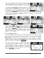
POS 2
When the//[key is pressed, the POS 2 screen appears.
Across the top line of this display a CD1
(Course Deviation Indicator) appears. The CD1
will only be active after waypoints have been
entered into the NAV unit memories, and one has
been selected as the destination waypoint.
N
34O14.714'
w 118" 35.236'
The CD1 is made up of a “boat-like” symbol
and a scale depicting your vessel’s deviation
from an intended track line to the destination.
On this CD1 screen, the ship symbol changes its
“angle” to show if the vessel is tending to close
to the track line, stay even with the line, or move
further OFF the line.
The CD1 range scale can be changed in the UNITS section of the System
Setups menu to set the width of the CD1 lane between plus or minus 0.1,0.3,
or OSnm from the track line. For example: When the scale is set to O.lnm,
the increments of the scale are .025 or approximately 150 feet to each mark.
POS 3
If you press them1 key again, the POS 3
screen appears.
The POS 3 display swaps the CD1 scale for the
digital version of the Cross Track error value
(XTE), Time-to-go to waypoint (TTG), local
Time, and Trip Log distance. On this screen you
can see a sample of the alarm readout appearing
to the right of the page ID in the bottom row.
OPERATION 3-9
POS 4
The POS 4 screen brings up the coordinates of
the destination waypoint to the screen so you can
compare the numbers. TDs are shown here because matching the TD coordinates is an ideal
way to return to a favorite wreck for fishing, TDs
are stored in the waypoint memories any time
you save a location as an Event or by direct entry
of TDs as a waypoint location. TDs are not saved
when Lat/Lons are entered as waypoints.
14096.2Irs
26160.4~s
Note also, that the sensor mode in use here is the Loran-C. The NAV 398,
when operating in the GPS mode can convert the GPS Lat/Lon readouts into
GPWLoran Time Differences (TDs]. Some users may find this calculation
useful to reference with their old loran coordinate logs.
The Loran GRI and the desired TD lines must be intitially entered in the
GPS Setup mode before this conversion page can work properly. However
having entered the required initial data, the conversion program can operate.
CAUTION
When TDs readouts are the result of calculations made from GPS derived
Lat/Lon data, the GPS signals are not subject to the same propagation errors
as loran signals and therefore will not match actual loran TD measurements
precisely. The TD readouts obtained from GPS are for relative comparison
only.
POS 5
If you press thelpos/llkey one more time, the
POS 5 screen appears and the readouts now
include displays of the course-made-good
(CMG), and velocity-towards-destination
(VTD). This readouts show the overall course
direction that you have made since starting
towards the current destination and your apparant speed. The readouts are of particular interest to sailboaters.
N 34O14.714'
w 118" 35.236'
OPERATION 3-10
:
.
-
.-
Anytime you switch from the Display modes to other functions and return
‘to the same mode, the last selected screen reappears. However, when the
power is turned OFF and then ON again, the last used POS screen is always
selected.
We’ve seen 5 different Position screens so far. There are also 4 Navigation
screens and 4 CD1 screens. Having so many screens of information available
sounds great, but there may be a few screens you will seldom use. The NAV
398 includes a means to customize the unit to enable only your favorite
screens. This is covered in the next section.
3.5.2 Customizing Display Modes
You can choose to show only your favorite
displays in any mode by pressing and holding the
particular mode key down for about 3 seconds.
When you hear the second beep, the mode custom page will appear.
POS CUSTOM PAGE
1
PO!31
0
2
POs2
0
3
POS3 0
4
POs4
0
5
POS5
0
PRESS NUYEW KEY FOR
ON/OFF; ENTER TO EXIT
For example: Press and hold the IM)s/il key down for the beep. The POS
custom page will appear.
Initially all the POS screens will be ON. This is indicated by the black dot
after the page name. To turn a page OFF, press the corresponding number
key. ( Press 2 to turn OFF page 2) The dot will now be hollow indicating the
page is OFF. The unit will permit you to turn OFF all displays in a mode,
except one. One display in every mode must be used. Pres@i?E@vhen the
menu is all set to return to the last used page of the mode.
You can always re-enter the Custom menu anytime and turn pages ON or
OFF. This is a convenient way for you to enable and quickly access the most
important pages without a lot of button pushing. Use them1 key to
customize the NAV screen selections. Use themikey for the CD1 screens.
3.5.3 NAVigation Display Mode
There are 4 NAVigation displays. They are
labeled NAVl NAV2, NAV 3, etc. along the
bottom of the screens. Pressing thej=Jkey
selects the NAV display mode and toggles
fromone NAV screen to the next. The NAV
displays feature large digits of the vessels’
course and speed, bearing and range to waypoints, and other navigation data.
OPERATION 3-11
z3Yn
iE3".
IT.7 nm
8.9 kt
Generally, the NAV screens are more useful once a waypoint has been
entered into the units’ memories . Once a waypoint destination is selected,
the NAVY display will feature large readouts of the destination Bearing
(BRG)and Distance-to-go (DTG) to the waypoint combined with the Course
and Speed readouts. . The readouts in the upper section of the display show
the XTE,TTG, local time, and trip log distance.
The NAV 2 display includes the same CD1 (Course Deviation Indicator) on
the top line as on the POS screens, if a waypoint has been selected as a
destination.
Press the m key to select the NAV3 display which features large
readouts of the waypoint BRG and DTG again, but combined with the digital
XTE OFF Course distance in 0.01 run units and steering direction indicator
plus the Time-to-go (TTG) readouts.
The NAV 4 screen combines the Course-made-good (CMG) and velocityto- destination (VTD) readouts with the COG and SPD readouts in the large
digits. The waypoint data is displayed in the upper boxes.
The flexibility of the NAVdisplays should be apparant now with so many
combinations of the important navigation data available. Use all of the
displays, or use the Custom menu for NAV to select only your favorite
screens for viewing.
3.5.4 CD1 Display Mode
If the NAV screens are more useful once a waypoint has been entered into
the units’ memories, the graphic CD1 displays are totally dependent on
waypoint navigation.
The key element of this display mode is the active view of steering down
the track lane towards the destination waypoint. As the vessel moves along,
the boat symbol orients itself to the track line showing the displacement from
OPERATION 3-12
_.,__ -, _ ,.- --
_*_
_
.._*.-.I
the line and whether the vessel is closing, paralleling, or opening away from the line. A bit of the
vessel track history appears behind the boat symbol.
Up ahead, the waypoint destination is in view. If
the destination is identified by a symbol or name,
the first character will be blinking near the target
area. Nearby waypoint symbols ( two closest to
vessel) may be in view on the screen if they are within range. If a route plan
is ON, the direction of the next leg is indicated by the slant of the track beyond
the destination symbol.
The various CD1 screens combine navigation readouts with the active CD1 graphic display. If for
some reason a waypoint is not selected, the BRG and
DTG readouts will be blank, WPT NO DEST appears
in the message window, and the destination target
symbol is not displayed.
3.5.5 Plot Display Mode
One of the most useful modes is the Tracking Plotter or Plot mode. Using
this mode you can record and retrace your vessels’ track to your best fishing
spots...and back home again. The Tracking Plotter also displays the symbols
or first letters and marks of waypoints and events used to mark your favorite
fishing locations on the plot screen.There are two Plot displays. The Plot
Mode is activated by pressing the IpLoT/ key.
The Plot 1 display appears as shown in the figure.
The location of your vessels’ position is indicated by
a blinking “+“. In addition, waypoints, event marks,
and the memorized vessel track line that is within the
range of the plot area will be shown, as well as your
current fishfinding information.
OPERATION 3-13
The PLOT 2 screen re-arranges the BRG and DTG
readouts and adds the vessels’ current position data to
the screen. The L/L readout can be turned OFF in the
PLOT DISPLAY menu for better viewing.
Plot Scales
The Plot size or scaling can be changed to show the
navigation area of interest by pressing the softkeys
indicated by thmorm{arrows. Plot scales available for the plot screen
are 0.125, 0.25, 0.5, 1, 2, 5, 10, 20, 50, 100, or 200 NM. The selected Plot
scale range is shown in the upper right corner of the Plot display next to the
UP arrow, for reference.
Recording a Track Line
The Track Plotter normally draws tracking lines on
the Plot screen as the vessel moves along. However,
these track lines are only “temporary” and are always
lost whenever changing plot scales, changing operating
modes, or upon turning the NAVunit OFF or ON...
UNLESS you decide to record the track line to memory.
PLOT MENU
TRACK MENU *
DISPIAY MENU +
SIMULATOR +
ON m
PRESS CLEAR TO EWT
You can record and save a single important vessel track of your vessel’s
trip to keep in memory so when you return home you may retrace the same
route. Recording a track is easily done by pressing thelm[ key while on
the Plot Display mode. The Plot menu appears.
Press thevlsoftkey to select the Track Menu.
The plotter can remember up to 300 track points, so
the recording interval selected will be important in
determining how quickly track memory will be used.
TRACK INTEFWAL I
.5 1 3 5 10 MN
Use a shorter time interval if the vessel’s route has
several turns or bends’ such as in rivers and waterways
Et-ME TRACK LINE
for saving track with more detail. Longer time recording intervals can be used when the trip is going to be
generally a straight line for long distances. The best
PRESS CLEAR TO EXIT
recording interval for long trips is “by distance” travelled. The recording intervals. can be selected in units of Time or Distance:
TIME INTERVALS: 30
seconds, 1,3,5, and 10 minutes.
DISTANCE INTERVALS: 0.2 or 0.5 nautical miles.
OFF is normally selected when track recording is not required.
OPERATION 3-14
.----.-u-
Press the [TRACK INTERVALlso&ey until the desired memory interval is
highlighted by the block. Now track recording will be ON.
The NAV unit has Auto Start/Stop plotting built in. So, if you should stop
along the way to fish, and forget to turn the track recording interval off, the
tracker should automatically stop plotting until you’re moving again.
All track points recorded will be “saved” in track memory until erased, or
unless overwritten by new track data. When track points are overwritten, the
newest track point #301 will replace old track point #l, track point #302
replaces #2, etc.
When you are finished recording the track, re-enter the TRACK menu and
select “OFF” with the TRACK INTERVAL softkey to turn the memory
recording interval to “OFF”.
Press the//key twice when you are ready to return to the previous
display mode to back out of the menus.
Erasing a Track Line
Since only one track line can be stored to memory at any time in the NAV
unit, it’s a good idea to erase the old track from memory before starting to
record a new track plot.
Just select TRACK menu from the PLOT menu by pressing thei-j
softkey. Press the[ ERASE TRACK LINElsof&ey and then press the-1
key to actually confirm that you wanted to erase the track memory. When
ImJis pressed, all track data will be erased.
Press themjkey when ready to return to the previous display mode
twice to back out of the menus.
Plot Display Menu
If the Plot screen becomes cluttered with the event and
waypoint symbols, the memorized track line, or the
Position readouts. The PLOT DISPLAY menu provides
options to turn marks, track or data ON or OFF.
r
Track
ON/OFF
Waypoints & Marks ON/ OFF
Position readout
ON/ OFF
I
PLOT DlSFJlAY MENU
TRACKLINE +
mm
MARKS +
mm
LLITDDATA
mm
PRESS CLEAR TO EXIT
OPERATION 3-15
-
+
l
I
Press lCLEAR[twice to return to the last selected display mode.
3.5.6 Simulator Mode
The NAV 398 includes a simulator mode which can
show simulated readouts on the various screens. There I
are dynamic simulated screens for both loran and GPS
and can be used to demonstate navigation to waypoints
and following route plans.
PLOT MENU
TRACK MENU +
DlSPlAY MENU +
To turn the simulator ON, be in Plot mode and press thelE\key . Press
the ~SIMULATOR~ sofIkey to ON. Conversely, to turn OFF the simulator,
press the/ SIMULATORlsof&ey a second time. When the simulator mode is
ON, “SIM” flashes on the various display screens.
3.5.7 Display Mode Operations
While you are on any of the POS, NAV, CDI, or PLOT display modes you
can perform the following operations:
Save an Event....Press thdm[ key.
The Event message will appear and show the
saved memory #.
l GO TO a Destination...Press
the wi key.
Enter the waypoint # using three digits and
then press(ENTET\1.
l
3.5.7.1 Saving Events
You can save your present position for future use as a waypoint when you
are in any of display modes. The EVENT data will be stored sequentially into
the next available waypoint memory just like a normal waypoint.
Just press theIm e s s a g e key.
p r oAm p t a p p e a r s t o p e r m i t y o u t o
select any other memory # location. If no keys are pressed in live seconds,
the message will show the Event memory number and then disappear.
If during the 5 second period you type in a different memory number and
press thdmlkey, the Event will be saved into the memory that you have
designated. If the memory number you typed was the same number as your
current destination, upon pressing the(ENTERl[key
the screen alerts you by
showing "DEST PT" flashing. If you typed the memory number by mistake
and really don’t want to overwrite your destination point, just press the
-Ikey. If you DO want to update the current destination coordinates,
OPERATION 3-16
then go ahead and press thelENTER(key. The memory will be updated, and
the screen returns back to the last POS, NAV, CDI, or PLOT display.
One caution on saving Events. For maximum accuracy, it’s best to be sitting
next to the desired location and let the readouts settle down for a few seconds
before pressing themjkey. If you are flying by a buoy at high speed,
the readouts will be displaying a position lagging behind the boat a short
distance. The faster you are moving, the greater the lag error will be.
Each time you store an event, the coordinates can be remembered as either
a loran, GPS, or DGPS position. Since there will be absolute position
differences when using the different systems, the NAV 398 memorizes the
type of position data (L, G, or DG) recorded for each event and shows the
indicator on the screens when the Event is used for a destination waypoint.
The indicators L, G, or DG appear immediately after the WPT characters on
the screen. In this way, the operator can use the matching systems to return
to Event locations more accurately.
It’s a very good idea to write the Event numbers and location descriptions
onto your paper waypoint log for future reference at the first opportunity.
3.5.7.2 GOT0 Destinations
After waypoints have been stored into the NAV unit memories, they can then
be selected for use as direct destinations. ThemGoTo/31 key permits the
operator to quickly select a waypoint destination. The GOT0 mode works
this way:
Press them] key.
Initially, when the-1 key is pressed, the
“GOT0 WF’T -‘I message appears in the destination
window area so you can input the desired destination
memory number. The message will show three
dashed lines until the first character is entered. Use
the numeric keys to type in the desired memory
number.
Example: Type 1-1,
6 1-1 f o r waypoint n u m b e r 6 .
When thelENTER(key is pressed, the desired waypoint becomes the destination waypoint. If you are on the NAV or CD1 screens, the display will change
the bargraph appearing on the top of the NAV screen and put the boat symbol
OPERATION 3-17
,/-_-
.-. _
- .
on track in the center. The
is ON the track line.
XTE
value will be set to “0.00 nm” since the vessel
Ideally, the helmsman sets the vessel’s heading with his steering compass
or autopilot to the bearing shown for the waypoint destination and begins
watching the CD1 scale at the top of the NAV display, the XTE digital value,
or the active graphic CD1 screen.
The helmsman then provides steering correction to keep the boat symbol
on the track line or if watching the digital XTE values, keep the digital value
at or near O.OOnm. This should take the vessel in the most direct path to the
destination waypoint while correcting for wind and current offsets along the
way. A good check point of correct steering is that your COG readout
eventually reads the original bearing to the waypoint, even though your actual
compass heading may be somewhat different.
Sometimes when steering to destinations it may be necessary to change
heading to avoid obstacles or other vessels in your path. Having deviated off
of your intended track, in many cases it’s easier just to start a new track from
where you are, than to return to the old track-to-waypoint.
To start a new track, just press thelwlkey, followed by the numbers
of the same waypoint. Then press theF[key and the NAV unit will
recalculate bearings, distance and TTG for the new track to the old destination
waypoint. The vessel is now ON the origin of the new intended track line and
the new bearing and distance to the destination is displayed. The XTE value
will be reset to “0.00 nm” since the vessel is ON the new line.
Sometimes you may prefer to turn OFF the waypoint destination calculation
and CD1 displays. To turn OFF the GOT0 operation press the/-key and
type 0, -1 "WPT NO DEST" will appear on the displays in the message
area and waypoint data will disappear from the NMEA 0 183 data output.
If you have not yet stored any waypoints, you will hear multiple beeps when
thqm[key is pressed. You will need to first save an Event or enter some
waypoint coordinates directly into the waypoint memories using one of the
methods discussed in section 3.6 of this chapter. TheI- key will also
give an error signal if you select an empty memory number by accident.
Waypoint coordinates must be stored in the memory before it can be selected
as a destination.
OPERATION 3-18
_ _ . . “_ . . -.
3.6 Entering Waypoints
3.6.1 General Waypoint Information
One of the key operations of the NAV 398 is to guide you to planned or
pre-programmed waypoint destinations from your present position. Waypoints can be entered into your 398 unit by using one of the following four
methods:
l Storing au “Event” (instantly saves ship’s present position as you pass
a buoy, enter a channel, or are sitting on top of a great fishing spot).
l Direct entry of Latitude/Longitude coordinates taken from marine
charts or light list, etc.
l Direct entry of Time Difference (TD’s) coordinates. These are usually
from a chart or a friend’s loran.
l By using Range and Bearing from your present position.
The NAV 398 has 500 internal waypoint memories for storing waypoint
position coordinates. These memories are numbered from #OOl to 499.
Whenever you decide to enter new waypoint position data, or recall old
waypoint information, the waypoint memory location number has to be
entered first. This is necessary so the NAV unit can place or retrieve the
information from the correct memory.
Since there are so many waypoint memories, it’s usually a good idea to
make a paper log of your stored waypoint data. The log should include the
Name of the waypoint, its Memory #, L/L and TD coordinates, the source of
the position data, and may be even the normal bearing and range from your
slip.
Some owners use certain numeric blocks of the memory locations to store
certain waypoint groups that make up trips or route plans. In this way, favorite
trips are saved and used over and over again by the number grouping selected.
Of course, the paper log book helps keep things straight for everyone.
3.6.2 Waypoint Directory
To gain access to the STORE WAY POINT operation, press thelwpT/4 key.
The WAYPOINT DIRECTORY appears on the
screen. The directory is used exclusively to pick
one of the memory locations for storing your
1 WAYPOINT D I R E C T O R Y
ENTER NEW WPT ?
e
ENTER WPT NO. a--
,
GOT0 WPT LIST
e
PRESS CLEAR TO EMT
OPERATION 3-19
--
.-__
1
STORE WAYPOINT OPERATIONS
(WPT
I-m-J
c-1
ENlERNEWWPT?
-_------
*
ENTER WPT NO. 0-w
UsEmmiKEY
FOR NEW ICONS
OOTO WFT LIST
1 KEv*FHID
3 KEY=REv
FRESS CIEAR TO EXIT
&
ND(T)
~W~b,pomlT
tapll
----e-w-
2b
USE~KEY
FOR NEW ICONS
de
1 KEv=FWO
X*
3 KEY=REv
CONllNUE
t
I
t
d
IATtLONG
zdX@QtOI
PRESS ENTER TO
IMR
STOAE wNKnNT
WPTloOZ
smPEwPrm
I
Note: II press CLEAR key. onb#
data to he last ENTER wed.
@ -
[SmRE
&II.
WAypolNl- 1
WPTnot
N
WC9 ENT TO ENTER UT
W’
-
t
+
’
e-*-w.
dears
TABLE OETIIIS
SdX
,tsc
aO#
D E F
GHI
MN0 SW
Yn 567
JKI. WR V W X 234 890
(STWIT 1002
ml = 9960
wPrsoO2
m, 2-s--e
6 2 3 6 .4
N 42°42.10’
42'42.QQ'me
7~2
9QQQQ.Q
w 07P1a66
-
.
-
-
t
---a
t
waypoint coordinate data. Pressing one of the softkeys will help you make
that selection.
ENTERNEWWPT?
waypoint memory.
Pressing this so&key selects next available empty
IENTERWPTNO. _ 1 If you want to store waypoint data into a particular
memory #, press the 1 ENTER WPT # (softkey, type the desired Wpt memory
#( X, X, X,), then press -1.
Example: Press 1 ENTER WPT # IO, 1, 0, wq, for Wpt. #lo.
If you happen to pick a memory number where the waypoint is “write
protected”, the contents of the memory may not be changed or overwritten
until the protection feature is removed. In this case, pressing thdmikey
will emit multiple beeps indicating an error.
If the memory is protected, you can always enter a different memory number
or go to the waypoint list for a look at the available waypoint memories.
OPERATION 3-20
.
_
.
__.,
-R
l-.-.w
/GOTO WAYPOINT LISA Press this softkey to see a directory of the waypoint
memories.
When the WAYPOINT LIST page appears, use the 1 (up) / 3 (down) numeric
keys (one at a time) to scroll through the memory listings in either direction.
When either key is held down, the scrolling operation speeds up so memories
can be accessed more quickly.
If you want to store a new waypoint or edit the existing information of a
selected (highlighted) waypoint memory, place the desired memory number
in the highlighted MEMORY # block. Then press the m key. You can
quickly change the name, symbol, or coordinate data of any waypoint
memory this way.
3.6.3 Naming Waypoints
As soon as a waypoint memory location is selected by one of the methods
available from the Waypoint Directory, the NAME WAYPOINT display appears.
On this display you can select various symbols and/or letters to "NAME"
the waypoint. The name can consist of up to 8 charNAM WAYPOINT
8002 1
I
acters. Each character “selected” at the EIRST
. .
nom will be used to designate that way- - - - - - - - point on the Plot display. Softkeys provide a quick
TdX b
USE= KEY
means to select the various characters or symbols for
FOR NEW ICONS
ao# &
the name.
1 KEY=FwD
3 KEY=REv
Find the desired symbol or character in the groups
next to the arrows on the screen. If the character is in
the group, press the softkey indicated by the arrow.
The characters in the group will be re-distributed next
to the arrows so you may choose the character directly.
If you do not see the character needed for the name,
press the m[ softkey to select new character
groups. The groups will appear in pairs as shown in
the figure.
NEXT b
PRESS ENTER TO CONTINUE
I
NAME wAYPolNT MO2 I
-------USEmKEY
T 8
FOR NEW ICONS
de
1 KEY=Fwo
Xb
3 KEY=REv
Repeat this operation, selecting characters or symbols and pressing the
softkeys, until the name is completed. To leave a space, you may press the
1 (FWD) key to skip past a entry prompt or place the character cursor over
OPERATION 3-21
any blank space in the typewriter box and then press the softkeys required to
add the character.
If you make a mistake, just position the a d x ABC GHI MN0
blinking cursor over the incorrect character o(Oe D E F J K L WR
with the 3 (REV) key and re-type the car.
rect character in its place.
STU YZl 567
VWX 294 8 9 0
When the NAME is complete, press thei- key. If you want to bypass
this page without naming the waypoint until later, just press thev[ key.
In the meantime, this “unnamed” waypoint will be designated by a “diamond”
shapped symbol on the plot screen.
3.6.4 Storing Waypoints
Once thelmkey
s c r e is pressed
e n on
, the t NAME
h WAYPOINT
e
d i s p l a y
changes to the STORE WAYPOINT TYPE screen so you can select the type of
coordinate data to enter.
If you wish to enter the waypoint coordinates in
Latitude/ Longitude, press thelm/softkey.
1 STORE WAYPOINT
TYPE 1
WFTJmo2
STORE WPT Bv:
lAT/LONG
&
To enter the waypoint coordinates in Loran-C
Time Differences, press theIs softkey.
To enter a waypoint position as a bearing and range from your present
position, press thelBEARING/DISTANCE 1 sofkey.
3.6.4.1 Storing by LAT/LON
Enter the waypoint Latitude coordinates by typing the numeric value in
degrees, minutes and hundreths of minutes. PresslENTERl when the value is
correct andm]again if the direction is OK. Use the softkey to select
“N”or “S”, if necessary.
Example: Press 2,7,1,0,1 ,S,IENTERUENTE-'
Latitude = N 27’ 10.15’
.
If you are editing or correcting an existing waypoint and the Latitude is already correct, just
press 1 ENTERI ENTER[ to advance directly to the
Longitude entry.
OPERATION 3-22
W
c
.
- - - -w’--
_._...
,
Enter the waypoint Longitude coordinates by typing the numeric value.
Begin with a “0” if the Longitude is less than 100’. Press 1-1 when the
value is correct anqn\again if the direction is displayed correctly. If
the indicated direction is incorrect, press the softkey for “E” or “w”.
Example: Press 0,8,2, 1, 0,2, S,Im(ENTER[ Long. = W 82’ 10.25’
When m[ is pressed, a "CALCULATING" message appears on the
display while the unit is storing the new waypoint and then the screen
changes back to the Waypoint Directory.
If you want to enter another waypoint, press IENTER NEW WAYPOINT?I.
NAME WAYPOINT page and advances the
waypoint memory number to next available memory. To designate a particular memory number to continue waypoint entries, press1 ENTER WPT NO. 1
If you want to recheck the new entry, press1 GOTO WAYPOINT LISA key. This key returns you to the
Press -1 if you are finished. This will return you back to the previous
display mode.
3.6.4.2. Storing by TDs
To enter the waypoint coordinates in Loran-C Time Differences, on the
STORE WAYPOINT menu press them softkey.
TJD 1
Enter the TD 1 coordinate by typing in the nu- IS-IWRE WAYPOINT
GRI
=
9960
merit value using all six digits. Press -J
~a02
m, 26238.4
when the TDl value is OK.
--m-m Example: Press 2,7, 1, 0, 1,5, -1.
TDl = 27101.5~s
lD2
om!x!.o_
Enter the TD2 coordinate by typing the numeric
value in using six digits. Press 1-1 when the TD2 value is OK.
Example: Press 4,4,2, 1, 0,2, -1 TD2 = 44210.2~s
When-1
t h e u n i ist w
pressed,
ill now calculate a “corrected” L/L
to store as the waypoint. During the calculation process the unit
will display a "CALCULATING" message on the screen. Please wait for
the message to disappear before continuing.
3.6.4.3 Storing by Bearing/distance
Occasionally, you may wish to enter a waypoint into memory by describing
the waypoint’s position as a bearing and distance from your own current
position. This is easily accomplished with your NAV unit.
However, while describing a range or distance from your vessel should not
be a problem, it is important to make sure your “bearing” information is in
“magnetic” IF the magnetic variation is “ON”.
If you wish to enter a waypoint position as a bearing and range from your
present position, press the lBEARING/DISTANCE 1 softkey on the STORE
WAYPOINTTYPE
menuscreen.
First, type the numeric value of the BEARING
(BRG) information. Begin the entry with “0” if the
bearing is less than 100’. Presdmlwhen the
bearing value is displayed correctly.
lsroRE WAywtHT
BID1
WPT ~02
Example: Press 0,4,5, -1 for
Bearing = 45’
N 42’42.10’
W 072O 10.66’
0
- - - --.-
Now the DISTANCE (RNG) can be entered using three digits (up to 99.9). If
the range is less than 10.0 miles, type a “0” first, followed by the remaining
two digits. Press -1 when the DISTANCE value is displayed correctly.
Example: Press 0,6,4,-i for Range = 6.4 nm.
If you make an error entering the numeric value, press t.hejj[ key.
Then retype the correct value.
When [B] is pressed, the display will calculate a L/L to store as the
waypoint. During this time, the unit will display a "CALCULATING" message.
Please wait for the message to disappear before continuing to the next
operation. The screen will change back to the Waypoint Directory.
3.6.5 Waypoint List Operations
As mentioned earlier, the Waypoint List lets you scan through the contents
of the waypoint memories. You can select any of the stored waypoints to
Edit, Copy, Protect, Measure or Erase from this page. In addition the
waypoint list, which is normally arranged in sequential memory # order, may
be re-sorted alphabetically by name for ease in locating specific waypoints
using themsoftkey.
OPERATION 3-24
3.6.5.1 Selecting Waypoints
To control the positioning of the list contents, the
1 (up) key lets you look at the listed waypoints at
- the top of the list; the 3 (down) key lets you look
at waypoints down the list. The waypoint # appearing in the highlighted block is the “selected”
waypoint and is the waypoint that can be operated
on if the [mJar m keys are pressed.
’ G
N ? 42 m 65--- ’
7 a~~Z&~i~{EOtT~
.
W 71’ 16. 34
I
3.6.5.2 Editing Waypoints
To add a name or symbol, or edit the L/L coordinate data to any selected
waypoint, just select-the waypoint using either method listed above. When
the memory # is highlighted, press the (EDIT1 key. This returns you to the
NAME WAYPOMT display so you can make the necessary changes. To Copy,
Erase, or Protect a particular waypoint or event mark just select the waypoint
using either method listed above. Press the @key and the display changes
to WAYPOINT-SF.
3.6.5.3 SF Operations
If you press the m key on the Waypoint List display, you can perform
some additional operations with the stored waypoint data including the
following:
A. Protecting Waypoints
While on the Waypoint List, place the number of
the waypoint to be “Protected” in the highlighted
box on the Waypoint List. Press the msoftkey.
On the WAYPOINT SF screen confirm that number
shown under PROTECTWPTSEVENTS is correct.
Press the ~PRoTECT wmm MmK[ sotiey to
turn “ON” the Protection feature.
RDTECT WPWEKNTS b
t!!! ON lpE0
EFUEWPTWENTS b
800
coPY~EAsuREwPls #
When a waypoint memory is “Protected” the character “P” is displayed on
the WAYPOINT LIST and Waypoint Directory screens, and the waypoint may
not be overwritten with new coordinate data until the protection is first turned
OFF or if a “Master Reset” of the unit is performed.
B. Erasing a Waypoint
While on the Waypoint List, place the number ofthe waypoint to be “erased”
in the highlighted box. Then press the q softkey for the WAYPOINT - SF
menu.
OPERATION 3-25
On the WAYPOINT SF screen, confirm that the number shown under ERASE
WAYPOMT is correct. Also verify that the Waypoint Protection feature for
the selected waypoint is OFF. Press the 1 E RASE WAYPOINT~ soflkey. The
waypoint will be erased.
WARNING !
Make sure that the waypoint to be erased is NOT selected as your
current destination. Only waypoints protected “manually” cannot
be accidentally erased.
C. Copying Waypoints
Waypoints can easily be transferred from one memory location to another
using the COPY feature. To Copy waypoints: Press them softkey on the
Waypoint List. On the Waypoint- SF menu press ICOPYIMEASURE WPTSl
softkey. When the COPY/MEAS. screen appears, press theI= softkey.
Then type the waypoint # (from) and press-1 Then press the waypoint
# (to) and press (ENTERI again.
Example: [=I 34-1 1, 5, (ENTEd
.
Wpt #3 is now copied into wpt #15.
D. Measuring between Waypoints
You can easily measure the bearing and range
between any two waypoints stored in memory
by pressing the/ COPY/MEASURE WPTS~ soflkey
on the WAYPOINT - SF screen.
when the COPYhIEAS.
WAYPOINTS screen appears, press thelMEAS.lsoft-
key. Then type the number of the “FROM” waypoint and -1 followed
by the number of the “TO” waypoint. Press thel[
T h e key.
calculated
bearing and range will then be displayed.
If you want to measure additional points, press the-1 softkey again.
The Fr and To digits will clear and you may re-enter a new pair of numbers.
Press Fj?[for the new Bearing/Range calculation.
Pressmjwhen you are finished to return to the Waypoint List.
OPERATION 3-26
.
--:-.
--a-
..T_”
3.7 Setting Alarms
The NAV 398 has three operator programmable alarms that you can set to
advise you when limits have been reached. The types of alarms available
are:
l ARRIVAL- Arrival at a waypoint.
l ANCHOR - Exceeds Anchor drift limit.
l OFF COURSE- Straying too far from track.
Whenever an alarm is set and activated, the audible beeper will sound and
the alarm characters will blink on-screen. You can set an Arrival alarm or
Anchor alarm, but not both types together. Press the[CLEARlkey to silence
the audio alarm.
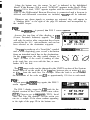
3.7.1 The Arrival Alarm
The Arrival alarm can be set to alert
you when you are within a specified ARRlvAL ,+ w 9 wAyw’NT
\
distance from your waypoint. The ar- CIRCLE ’
J
rivalalarmcanbesetErom0.01 to9.99 y l %@t%#E?rHEN
\
,ARFUVAL CIRCLE
nautical miles (run).
I!3
-b
#
4
!K
To set an Arrival alarm:
Press thel]key. The SET NAV
ALARMS screen appears. This is the alarm set-up screen. Press theIsoftkey. Then enter the distance value for the desired arrival alarm zone with
the numeric keys. Press-to finish the entry and exit back to the last
used display mode.
Example: To set an Arrival zone of 0.06 nautical
miles; Pres$KiZ$ press 0 , 1 , 0 , m.
There are several factors which should be considered when setting the arrival alarm zone distance. Among these factors are: the speed your
vessel is or will be traveling, the weather conditions (foggy, rain, clear, etc.), and your familiarity
with the surroundings.
1
SET NAVALARMS
0 10
-‘--
ARRIVAL 4
ANCHOR 4
0
-9 0-- 0 OFF-COURSE4
PRESS CLEAR TO EXIT
A vessel traveling at 30 knots, will travel 180,000
ft/hour, 3000 ft/minute, or 50 ft/sec., so an arrival alarm set to 0.0 lnm gives
you 1.2 seconds to react. If the alarm were set to 0.2nm, (1200 ft) you will
have 24 seconds to decide your course of action. In the NAV 398 the arrival
OPERATION 3-27
-1-.
1
alarm is initially set to 0.10 nm from the factory to provide an arrival alert in
the event that one is not set by the operator.
3.7.2 The Anchor Alarm
The anchor alarm is intended to be used to monitor your vessel’s position
while at anchor. If the vessel begins to drift beyond the entered distance of
the anchor alarm, the alarm wiII sound off and notify the crew of the possible
dragging of the anchor.
The distance value to input for the anEVENT
* - ,WAYPOINT
char alarm zone depends on many fat- tEioR, )
J
tors, such as the amount of anchor line +-+
\
t
:
out and the depth, the proximity of other
\
SOUNDS WHEN
objects or vessels, and weather condi‘4 I9 c /AlARh4S
VESSEL CROSSES ZONE
tions. However, the incremental distance that can be entered is 0.01 nautical
mile steps which is equivalent to approximately 60 feet or 18 meters per step.
The first task, when entering an anchor watch alarm, is to press thd-[
key as you drop anchor to store your present position as a waypoint. Make
a mental note of the EVENT memory # (number), The number appears for
approximately 3 seconds on the dispIay and certainly is the last used
waypoint. If you miss seeing the number, just check the waypoint list. The
stored Event will be the highlighted waypoint on the list.
Press thepALM/ key. Press the -1 softkey. Use the numeric keys
to enter the drift limit distance. Input values can range from .Ol to 9.99
nautical miles. Pres$mJwhen the value is correct to set the anchor watch
alarm.
Now press thdm[ key, and enter the EVENT # that you’ve just saved
to be your destination waypoint and then press-1 The anchor watch is
now set and will be monitoring the anchor drop point.
Example: To set an anchor limit of 100 yards, (.05nm at 2000 yd/nm),type
0, S.JZFZiZlfor .05nm (300 feet).
In the event that you drift beyond the distance set for the anchor watch alarm,
the audio beeper will sound and the ANC characters will be indicated
on-screen in the alarm warning area. PressvIto silence the audible
alarm.
OPERATION 3-28
3.7.3 Off-Course Alarm
The Off-Course alarm can be used to
alert you when you are steering to a
specific waypoint destination if your
vessel strays too far away from your ./?‘O
intended track line to the selected way- Cc
.--**-*
point. This is particularly useful if you &G@
N---d**
are using an autopilot to monitor its effectiveness.
To set the Off-Course alarm, press theplkey. Press the(OFF COURsEI
softkey. Using the numeric keys, enter the desired distance that represents
the maximum margin that you would allow for being off course, then press
the/mikey to set the alarm into operation.
Example: Press 0, l,OjENTER[, for an XTE alarm of 0.1 run.
Whenever the XTE alarm is set and the XTE distance exceeds the alarm
value, the alarm will be activated, the audible beeper will sound and XTE
characters will appear on-screen in the alarm warning area. Presdm[ to
silence the audio beeper.
The values set for the alarms will remain in memory until changed by the
operator. As mentioned earlier, you can set the arrival alarm or the anchor
alarm, but not both. The alarms can be set to OFF anytime by accessing the
desired alarm in menu and entering “0” as the alarm value.
3.8 Man-overboard Mode
This important feature is useful if, while underway, something or someone
falls overboard. Press thelE[key . This puts the NAV unit into the special
MOB display mode and a series of special operations begin.
The MOB display appears and shows the position where the event occurred as waypoint #999.
Own ship and the MOB are joined by a dotted line
and constant readings of BRG and DTG are provided to the MOB position. The Plot scale is
automatically set to the 0.5nm scale for the optimum view, although the scale can be set for the
amount of detail required for recovery.
a
OPERATION 3-29
The arrival alarm is preset to 0. lnm and activates whenever you are within
this area relative to the MOB. As always, press the -1 key to silence
the audible alarm.
To Cancel the MAN-Overboard function and return to the Position displaypress and hold the[MOB/8lkey for about 3 to 4 seconds until a second
beep is heard and the MOB characters disappear from the screen.
NOTE: The MOB location is not “Saved” to memory permanently and the
location will be lost when the MOB mode is cancelled. If you will need to
retain the location for some reason, mark the location with themjkey
after the mode is cancelled.
3.9 Route Plans
The NAV 398 allows you to create up to 10 route plans using a maximum
of 200 waypoints or 20 per each route. When the//key is pressed, the
display will show the Route Mode menu, which will allow you to choose to
Make, Follow, or Edit a route plan. The figure below provides an overview
of the screens that are used for implementing the various route functions.
SELSClIK)UTENUWEN
I
--. .
.- - +NlJ9
ROUTE PLAN
OPERAllONS
1
mlgcrEuTOmmer
LEG1
1
L
PRESSENTTOEND
NOTE: AUTO SEOUENCE AT AJWVAJ.
pERpEwm2uuR [OTG = UIM
\ OPERATION 3-30
1
3.9.1 Making Route Plans.
Press themlkey and the "ROUTE
screen appears. Press thejm[softkey.
MODE
-'I
When the lm[key is pressed, the MAKE ROUTE
Selection screen appears to prompt you to choose a
route number for your route plan. Choose any number
from those listed on the screen and press(ENTER(
MAKE ROUTE
SELECT NOWE NUYBER
Example: 4, -1, for route plan 4.
m 67690
!
The display willchangeto the MAKE ROUTELEGS
display and prompt you to enter your starting waypoint. Enter the waypoint # of the first point in the I
route. Then press -1.
If the memory number
you typed does not contain waypoint data, the unit will
emit multiple beeps whe@i%ZJis pressed and return
the prompts to ---.
Example: Type 4,mlfor waypoint # 004.
FROMtOlJ4 TO
FROM#6l!JTO
#g
The screen will show the From waypoint as 004 and
add the “TO” entry line for the next waypoint number
entry. Type the digits of the next point in the route plan. If you make a
mistake, press the)m[key and re-type the number.
Example: Type 1,5, (ENTERlfor
waypoint # 0 15.
The Name of the waypoint, and BRG/DTG of the leg will be calculated and
displayed in the lower section of the screen. If the waypoint is correct, press
thelENTER]key and the display will change showing the “From” waypoint
now as #O 15. The prompt “LEG” now appears and to enter the next waypoint
in your route plan press thd=j softkey.
LEG 002 now appears and the last waypoint you entered has become the
“From” waypoint in leg 2. Type in the digits of the next waypoint #023 and
presdm1 The LEG prompt re-appears again for adding LEG 003. Press
thej=J softkey again to continue adding waypoint legs into the route plan.
OPERATION 3-31
_1
-,
----
--*-
When you have completed the entry of all the waypoints for a particular
route plan, just press thewqkey. The new route plan will be stored and
the display will promptly return to the last used Display mode.
3.9.2 FollowRoute Plans
Once a route plan has been made and saved into I/
memory, it can be recalled to Followed or to be Edited.
Press the-key. The ROUTE MODE screen will
appear. Press theI- softkey.
when the FOLLOW ROUTE Selector screen appears
use the numeric keys to type the number of the route
plan to FOLLOW.
SEQUENCE MODE 4
mm MAN O F F
Example Press 4,lm(for route plan # 4.
The FOLLOW ROUTE Setup screen appears. Once
route plans have been made, this screen permits engagement of route sequence operation.
ThelSEQUENCE MODq softkey enables you to select the type of waypoint
sequencing mode between AUTO or MANUAL. The other choice turns the
route sequence mode to OFF. Press th+EQUENCE MODElsoftkey to highlight the desired sequencing mode.
AUTO SEQUENCING
mode automatically steps from one waypoint to the
next when the arrival perpedicular point has been detected.
In MANUAL SEQUENCING
mode, the unit sounds the arrival akrn and the
operator will manually press the-1 key to step to the next leg in the
route plan when it is safe to do so.
When the Sequencing mode is decided, the next
step is to decide to follow the route in the Forward
direction (first to last), or to follow the route in Reverse (last to first). Just press the/mor//qdirection softkey to advance to the next screen.
1
FOLLOW ROUTE
SET ARRIVAL DISTANCE
Il. 1ONM
The last display shows the Arrival alarm distance that
PRESS ENT TO END
will be used to alert you as each waypoint is approached. You may accept the limit by pressing thd=lkey or enter a
limit of your choice on this screen. To enter a new arrival zone limit, type
the numbers of the desired limit distance and press the/e[key.
OPERATION 3-32
t 41
When-is pressed the route sequence mode, will be ON. The route
number will be displayed in the left corner of the waypoint information bar
on the POS, NAV, or CD1 screens and the first point of the route plan
becomes your initial destination, unless you happen to already be at the first
point of the route.
While you are following the route plan you may press themlkey
anytime to bypass the next point in the route plan.
Turning the Route OFF
The route plan can be conveniently turned OFF anytime by pressing the
the FOLLOW ROUTE screen press the
One other method of turning the route sequence to OFF is a bit indirect but
if you press thdmlkey to select any waypoint that is not part of the route
plan, or press ml, OJm , the route will be turned OFF.
3.9.3 Editing Route Plans
The EDIT ROUTE mode is used to INSERT or
plan or to ERASE a route plan in its’ entirety.
DELETE
waypoints in a route
Press the /ROUTE/51 key. Press thelm[ softkey. when the EDIT ROUTE
Selection screen appears, select the route number you 1
EDIT ROWE
wish to edit. Press//[
SELECT ROUTE NUMBW
123@5
On the EDIT ROUTE screen the route legs can be
examined and the bearing and distance of the highm
fi ERASEROUTE +
lighted leg of the route plan displayed. If changes are
e
necessary, you can insert or delete waypoints in the B
MESS CLEANToEaT
legs in a route by performing the following key opera- 1
tions:
The EDIT ROUTE display shows the Route # and
the leg containing the first two waypoint #‘s in the
route. To see other waypoints in the legs of the route,
of interest in the highlighted block to check the bearing
and distance.
OPERATION 3-33
I
Press theI=j key puts the screen into an Edit condition so you can
INSERT or DELETE waypoints. Notice that two softkeys ILEG and m
(insert) appear on the screen.
To INSERT a Waypoint
For example; to insert a new waypoint between waypoints #006 and #036,
press(LEGI[ and them[arrow until you see the leg containing Fr 006/to
036. If this is where you would like to INSERT the new waypoint, Press the
msoftkey Type the new waypoint number ( # 002) and pressF1 The
new waypoint will now appear between 006,002,036.
To DELETE a Waypoint
To delete a waypoint from a route plan, press thelLEG1 key until the leg
where the waypoint shouid be deleted is displayed. For example; to delete
waypoint SO36 in the example above, pres~~~until you see Fr 006/ to
036. Then pressllto EDIT and pressmqagain to DELETE #036.
The FROM waypoint 036 will disappear the route string will be joined less
waypoint 036 ( deleted from route; not from waypoint memory).
JWhen you are finished,
B
press theI- key to end the editing session and return to the Display
mode. If you press the[CLEAR[key here (which is normally done on other
menus) you will accidently remain in the EDIT screen and continue deleting
waypoints from the route against your will.
3.9.4 Erasing Route Plans
To ERASE a route plan, select the Route mode with thevlkey.
P r e s s
wqon the ROUTE MODE Directory. Type in the route number to be erased
and then press the # ERASE ROUTE softkey. The message WJRE? PRESS
ENTER" will appear. To ERASE the route, presdm{
If you have a change
of heart, pressjjlto abandon the ERASE request and return to the Display
mode.
3.10 TheplKey
One of the smallest, but most important keys on the NAV 398 is the-1
key. This key controls access to the screens which set up the operating
parameters for the sensors, the display system, and for the navigation
calculations and readouts,
In the Menu pages you will find that the operations are very simple and
direct and the most difficult task will be to remember which menu holds the
OPERATION 334
..- . . -. . _,._ _
function or setup that requires change. The paragraphs that follow will
endeavor to provide simple guidelines for you.
7
MENU
1
SYSTEMSTATUSMENU
]
wrfUNlTS
’
.
DATAINWJT
NW SETUPS *
I
.
4
NAV SENPE MENU
1
mur 0
YL(lNEllt
r
MANUAL vAnlAmll
)
lb
SIGNALSTATUS )
COURSi3BEAJlINQS
mEscl.sAnmm
) -
TO
SJgnol
Slcluc
PoSmONCORR ) -
-)
MENU OPERATIONS mu
AVERAGING
1
AVENAGING
LORAN
i
I
I
( mSmONCORR.
LORAN1
N 00.00’
w 00.00’
I
msssapumoQT
r
1
GEODETICSVSTEM
WaMl
. 7;
.
dul.
NM
0
mEJsamnmsxi7
+--a
[ POSrnON
GPSZ.]
COFW
“;:;i
drn
*
DGPS BEACON SELECT .
-4
mEvlous 0
m
DGR
MENU
msssamnmm
3.10.1 Main Menu Directory
The figure above shows the selection paths that are available when the
-key is actuated. The Svstem setuos control Data Inputs/ Outputs, Units
of Measure and Language. The NAV setuns change the parameters for
calculating and displaying the navigation data. Items that can be altered are
Course & Bearing readouts, Speed averaging, and Position corrections. The
enal Status screens display the signal reception and tracking status and
allow initialization input and manual control functions.
When therMENU/key is pressed and the MAIN MENU Directory is displayed, pressing the indicated softkeys will place you in the secondary
memis. When you are ready to leave the secondary menu, press theI=
key. You will be returned to the MAIN MENU Directory.
If you are finished with setups in the menus, press the// key one more
time to return back to the last Display mode screen.
OPERATION 335
3.10.2 Signal Status Pages
The SIGNAL STATUS displays are used to show the conditions of signal
acquisition and tracking of the attached sensors and thereby indicate the
quality of the position fix. If the NAV unit is using both a loran and GPS
sensor, the status of the sensor in use is always displayed. You may choose
GPS or Loran operation while in the normal Display modes by pressing the
k e y .
vl
3.10.2.1 Loran Signal Status
When operating in the Loran-C mode and the\SICNAL STATUS1 softkey is
pressed, the first screen advises which type of “stats” you will be looking at.
The "LORAN STATUS" screen will appear as shown in the figure below.
STATUS MENUS
LORAN C STATUS
mou ‘SIGNK” ON
STATUS MENU IF LOWN
SEIJXTEDASNAVTVPE
IS
I
BA
ENTER
PRESS
ENTER TO GElURN
S2@ -
TOGGLES
moht r4x
I
On this display the characters show the selected GRI and the Secondaries
being received and used for L/L calculations in the Signal box (prominently
featured on the page). The Master (M) station is shown first in the box. As
each Secondary signal is received it becomes listed in the box. The signals
appear in the list in the order in which they are received and not necessarily
in numerical order.
The selected GRI number appears in the top section of the box. An “A” may
appear to the right of the GRI to indicate that the 508 sensor is operating in
the automatic GRI and secondary selection mode. If the “A” is not ON, the
sensor is in the “manual” Station selection mode.
OPERATION 336
As you may remember from reading the basic loran information in the
R~~NAV 508 manual, the secondaries get their numbers by using the first
digit of their normal time delay. On this display you actually see the TDs of
all the loran signals, but the two “S” numbers highlighted in the reverse block
characters at the left side are the stations being used to get your Lat./Long
readout. So in the Status page example in the preceeding figure, the ” 1“) “4”
line and the “6” lines are being received.
SNR Display
You can see a display of the SNR’s (signal-to -noise ratio) levels for the
Master and all received secondaries in the SNR column. The SNR level is
important because it affects the quality of the position fix and certainly
acquisition time.
The time required to select the correct cycle of the received loran signal is
directly related to the received strength of the signal (SNR). If the signals are
very weak, it usually takes much longer to “Lock-on” and track the signals
and display your position. The table below shows the general range for SNR
levels vs time of acquisition.
f3NR Table
SNR LEVEL
STATUS
70 - 99
50 - 69
15-49
o- 14
Good
Fair
Poor
Bad
TIME TO LOCK
Up to 3 minutes
Up to 7 minutes
Unpredictable
Try the GPS
.
SIGNALSTATUS LORAN ]
Track Status
The Track Status numbers appearing in the
right hand column labled "TRACK" vary from 0
to 8’s during the acquisition process with an “8”
indicating that the loran is “Locked-on” and
tracking that particular station.
EST 41
STA 11
N 42 05.32’ ECD 4,
w 071 10.14’
PRESS CLEAR TO EXIT
When one of the signals disappears or becomes too weak to be tracked, the
corresponding status number may go to “9“ until the signal is recovered. If
the signal is not recovered within 5 minutes, the signal will be considered
“1ost“ and status number reverts to 0 (re-initiating search).
OPERATION 337
I’
STATION
m 9960
B
SELECTION
I-l I
1
AUTO STATION @
mom
NEWGRI?
D TOGGLES TRW REGISTERED GRls
6 J
Sl, S2 SELECTION
ml
I
NEW Sl. S2? + B
St12
PRESS ENTER TO RETURN
GRI
3.10.2.3 Station Selection Mode
If for some reason the SNR values or the Track Status of the SELECTED
stations in the Automatic Station Select mode are poor and the loran will not
lock-on, you can choose Manual Station mode and make station selections
manually using the signals that are received in good quality. Just press the
When you see the "STATION SELECTION" screen, you only need to press
either thdw1 softkey to select a different GRI from the internal GRI
list or the[msl,sz?lsoftkey to change the secondaries stations only.
Selecting GRIs Manually
Thdm[softkey toggles through the list in numerical order. The GRI
names appear on the screen directly below the GRI number on the screen. If
you’re not sure which GRI to enter, the list of worldwide loran GRI’s appears
below.
WORLDWIDELORANCCHAINS
4990
5930
5970
5990
7170
7270
7950
7960
7970
7980
7990
5980
C.PACIFIC
E.CANADA
E.ASIA(CO.LION
W.CANADA
SAUDIARABIASO.
NEWFOUNDLAND EC
CHAYKA E.ASIA
GULFOFALASKA
NORWEGIANCHAIN
S.E.USA
MEDITERRANEANSEA
ATTUCHAWKA
8000
8290
8940
8970
8990
9610
9940
9960
9970
9980
9990
7930
CHEUROPE
NO.CEN.USA
FRENCH
GREATLAKES
ARABIANORTH
SO.CENUSA
WESTCOASTUSA
NEUSA
NWPACIFIC
ICELAND
NORTHPACIFIC
LABRADOR(OffAirin Nov94)
OPERATION 3-39
Selection of Secondaries
When pS1,S2?( softkey is pressed, the screen will change to the ” S 1,
$2 Selection” screen. On this page the top line of large characters shows the
received secondary stations from the selected GRI.
To enter the two secondary stations for S 1 and $2 that you would prefer to
use for your Lat/Lon calculations, Press thasoftkey for a NEW S 1 station
and using the numeric keys, type the number of the desired station. Then
pres$%%@ The softkey arrows will return. At this point you may coose
a new $2 or press/ZiKQone more time to return to the Signal Status page.
For S2, press themsoftkey and using the numeric keys, type the number
of the desired station for S2. Then presdm1.
Example: a 2, (-1 for S 1 of 2
/BJ 4, @EEQ for S2 of 4
Press
when finished to return to the
. Signal Status page.
x
A
b
I&
I !i
3.10.2.4 GPS Signal Status
When in the GPS mode and theI- key is
pressed and ISIGNAL STATUS{ is’ selected from
the Menu Directory, the GPS Status screen will ,y. :j@&
appear and show the GPS satellite signals.
I . PRESS
0141MT
SF*
CLEARTO EXIT
The “Satellites Tracked” display shows the identification numbers( ID) of
the satellites being received, tracked, and used for L/L calculations in the
reverse block characters. The Raystar 108 sensor is usually tracking 4-6
satellites at any one time and can track up to eight, if visible. So, seeing 6 to
8 blocks illuminated is not at all unusual.
In the column below each Sat ID # you can see see the individual satellite’s
azimuth angle, it’s elevation angle from the horizon, and signal level (SNR).
The data is displayed for all satellites being received.
Below the Status box the HDOP number appears and provides the current
fix quality. This rates both the strength of the satellite signals as well as the
geometry of the satellite positions. Typical HDOP numbers for a good fix
are 2 or less. Fair HDOP values are 4 or less; Poor HDOPs are over 5.
t OPERATION 3-40
I
In the title box, the fix type is displayed at the right end. Here, you will see
either 3D or 2D characters. The 2D mode is a two-dimensional position fix
mode that will not factor the calculated altitude (antenna height) into the L/L
position solution. AUTO mode calculates altitude. Generally, the 2D mode
works the best for marine navigation.
The Status display also includes readouts of your estimated position, local
date and time, and antenna height.
There are two softkeys on the GPS Status screen. Thmsoftkey accesses
the GPS sensor Initialization sequence. Thm softkey permits special setups
that effect the GPS position fixing or readout displays. The next sections
cover the GPS initialization sequence.
3.10.2.5 Initializing GPS Sensors
The following paragraphs describes the series of initialization inputs to be
checked when your NAV unit is to be operated with the RAYSTAR 100 or
RAYSTAR 108 GPS Sensors. JJ
.
de when the awtesenso r is connected,
. When the-1 key is pressed andlSIGNAL STATUS1 is selected from the
Menu Directory while using the GPS mode, the GPS Status screen will
appear and show the GPS satellite signals. Press them softkey to start the
sequence of initial entries. The first screen appears as below:
Estimated Position
When the EST LATITUDE message appears, the current Latitude entry will
be displayed. To update the entry, you should always re-type the correct,
numbers for you latitude using the numeric keys. Even if the entry is OK, we
recommend thatthis entry, by pressing thelm[key.
L
THEN PRESS ENTER
THEN PRESS ENTER
wnnu
ESTIMATED POSITION
nn.na
b
ENTERING INITIAL POSITION
I
Example: Press 4,2,0,5,0,0~~,~/,
for N42’05.00’
Check the direction displayed to the left of the Latitude. Use thakey to
change “S” to “N” or vice versa. Press-it0 save the Latitude.
Estimated Longitude
The prompt now moves to request your Longitude entry . Type in the correct
longitude value. Add a “0” for Longitudes below 100 degrees. Pres!$Ml
Example: Press 0,6,9,5,9,8,5,[~,~~,
for W69’ 59.85’
Check the direction displayed to the left of the Longitude. Press thelE/wI
key to change “w” to “E” or vice versa. Press (ENTER1 to complete the
longitude entry.
Whenvlis pressed to complete your Longitude entry, you will be
prompted to enter the antenna height.
Antenna Height Entry
The display changes and prompts to "ENTER ANT HEIGHT" above sea level
in METERS (3.28 feet = 1 meter) or in "FEET". Enter the numeric value of
you antennas height above the water. Then press-j. When thdm[
softkey appears on the screen, press the softkey only if you want to change
the units from meters to feet or vice versa. The currnt units selection appears
after the antenna height digits on the display. Then presdmbgain.
When\-1 is pressed to accept your antenna
height, the unit will advance the message prompt
to request the date entry.
Date Entry
For this entry you need to type in sequence the
two digits of the Month, followed by two digits
for theDay, followed by two digits for the current
Year. When the readout looks OK, press IENTER]
.
-94
IME 18.25.14
I
GRI NO. 9960
Sf 14 9
s2 26 II
For May 7,94, press 0,5,07,94 -1
When (ENTER7 is pressed to accept the Date
entry, the display advances to enter the Local
time.
, OPERATION 3-42
41
PRESS ENTER TO RETURN
LNOTE:
RETURNS TO
SIGNAL STATUS
Local Time Entry
When 1-1 is pressed to accept the Date entry, the display will prompt
you to enter Local time. Enter the hour and minutes (+/- 15 minutes) using
the 24 hour format. In the 24 hour format, 9:OOa.m. is shown as 0900,
3:OOp.m. is 1500,10:00p.m. is 2200. Since each entry is two digits, enter “0”
first when the hour or the minutes value is less than 10.
Example: Press 0,9,0,5,~~for
or
Press 1,3,0,7lmjfor
9:05a.m.
1:07p.m.
The last screen of this sequence prompts you to enter the GRI number of’
the loran chain serving your area and the first two digits of the TDs that
would normally be used in that area.
Loran GRI Selection
When the GRI entry prompt appears, the GRI that serves the area of your
esitmated L/L position will appear in the entry window. If the GRI is correct
then it is only necessary to designate the TD numbers.
Press Sl softkey and type two digits of first TD. Press=1 When the
softkey arrows re-appear, press the S2 softkey and type the two digits of S2.
Then pres5jvto input the S2 entry.
If the GRI number was not correct, press themsoftkey. Re-type the
f y o u a r e fished, f o l l o w t h e
desired GRI number. Then press I1-4
message at the bottom of the page to press the[mqkey and return back
to the GPS Signal Status page.
3.10.2.6 SF for GPS Status
On the GPS Signal Status screen one key remains. The softkey is them(specia1 functions)
key.
GPS Fix Mode
When theSF( key is pressed, the first of two SF
menus (shown in the figure) appear. Here you
may select the type of GPS fix. The choices are 2D
and AUTO (3D). The 2D mode is recommended for
marine use, Press the softkey for 2D fix mode.
OPERATION 3-43
lWTHT oolomt.
bWT)
TNEN PRESS ENTER
SIOPERATIONS
GNAiY&T”S
NOTE:
PRESS
Press the[Gikey
RETURNS To
slsw sThW.9
arm To izxm
to return to the Main Menu Directory.
L/L Digits ( L/L Resolution)
The next item of the SF menu selects the latitude/longitude readout resolution . The readouts can display to VlOOths of a minute or l/lOOOths of a
minute. The readouts are set to .OO’ from the factory. Press the Isoftkey for .OOO readouts.
When the lmjsoftkey is pressed , the SF2 menu will appear. On this
menu you can set the Time & Date readouts on the GPS Signal Status page
to show the UTC Time & Date when the/ml softkey is pressed.
The last menu item starts the SATELLITE SEARCH mode. when this softkey
is pressed it is requesting the GPS sensor to refresh its almanac data in
memory. The message prompt will ask you to press them[key if you
wish to proceed. Press PJ if you choose to abandon a SATELLITE
SEARCH. The accumulation of almanac data normally takes anywhere from
15 minutes up to 30 minutes.
OPERATION 3-44
3.10.3 System Setups
In the System Set-up menu the type and style of the
various readouts and messages can be set to your preference. This menu also controls the Data input/Output
parameters. To see the System menu, from the POS,
NAV, or CD1 screen press thejRi$Qkey. On the Main
MenuDirectory,press ~~~SYSTEMSETUP[~~~&~~.
1
MAIN MENU DIFIECTOR~
sYsTEMSETuPs *
NAY SETUPS )
SIGNAL STATUS )
mEssawmm
3.10.3.1 Display Type
The first item on the SYSTEM STATUS menu is the NAV DISPLAY TYPE
selection. When the(~~~ DISPLAY TYPE/ softkey is pressed, the position
coordinates will be shown in TD coordinates if TD is highlighted. When L/L
is selected, all position coordinates appear in Latitude/ Longitude coordinate
format.
3.10.3.2 Units Menu
When thelm(softkey is pressed on the system status menu, a second
menu SYSTEM UNITS appears. On this screen the units for distance and speed,
language, and CD1 scaling may be selected.
Themlkey appears again
on the UNITS menu and this
time toggles the selection of
NM/KTS, SM/MPH, or
KIWKPH for distance/speed
units. PresslUNITS( until the
desired units are highlighted.
I[
1
SYSTEMSTATUSUENU
SY%USTAlUS
1
w
I
UNITSJl
NAvDlSPlAYTYPE lb
1
.3
.5
CUSCALE)
mssasmmsm
J
WDm
UNITS )
SYSTEM STATUS OAT111
Language
Each time theIkey is pressed one of six languages may be selected for the
text on displays and in menus. English is the default language. As the key is
pressed DEUTSCH,FRANCE,ESPANOL,NORSK, and ITALIAN maybeselected.
CD1 Scale Range
This menu item sets the span of the CD1 scale used on all CD1 displays in
CDI, NAV, and POS modes. The selections available are 0.1, 0.3, and 0.5
nm. These are scale limits as measured from midscale to each end. The value
highlighted in the block is the selected value. Press thelSCALE(softkey
to highlight your choice.
OPERATION 3-45
3.10.3.3 DATA IN/OUT Menus
When you are on the SYSTEM SETUP menu and press the)DATA IN/OUT)
sofkey the SYSTEM STATUS- DATA menu will appear. This menu till control
the format of the data to output and execute the transfer of waypoints and
routes in and out of the NAV unit.
To select the Data output format INMEA DATA OUTlsoftkey to highlight
0 180, or 0 183 NMEA data formats. The next press of the softkey will select
SeaTalk data format.
NMEA 0 180 is an old data format that is intended to provide XTE steering
data to older autopilots.
NMEA0183 is the current standard data
interface used between marine electronic
equipments. The list of NMEA 0 183 sentences outputted by the NAV 398 can be
found on page 2-6 of this manual.
OUTPUT ROUTE DATA )
0 1 0 0 m SEATALK
SEATAI,K is a bi-directional data format used for communication between
Autohelm Instruments and Raytheon marine products.
Press the[NMEA
DATA OUTjsoftkey to highlight your choice.
MEMORY DATA OUT
This menu item enables the transfer of waypoint and route data from
internal memory of the NAV unit to a PC file. The data is output in the
NMEA 0 183 format standard using the WPL and RTE sentences. This mode
can be most useful to download the memory contents for editing and
reloading. The mode is also useful to save a file record of the memories in
the event a Master Reset must be executed.
To transfer the Memory Data out, press thdMEMORY DATA OUT1 so&key.
The MEMORY DATA OUT screen will appear. The Data output connections (Yellow & Green wires of the power cable) should be connected to the
COMl or COM2 input of your PC. Verify that the line settings are set for:
8 Bit, 4800 baud, no parity, 1 start bit, 1 stop bit.
OPERATION 3-46
Designate a drive, path, and file for the data to be saved into. When the PC
iS all Set, press thelOUTPUT WPT DATA1 or the [OUTPUT ROUTE DATA1
sofkeys to begin the memory transfer. The screen will show the message
"SENDINGWPDATAOUT" anda” UPLOADING" willblinkonthescreenduring
the transfer process. The time to upload the data will depend on the number
of memory elements to transfer since up to 500 memories may be involved.
The UPLOADING message will go out when the transfer is completed.
MEMORYDATAINPUT
When you are ready to transfer the PC files of route plans or waypoints into
the NAV unit memories, please verify that the Data Input connections in the
power cable assembly are now connected to the PC COMl or COM2 port.
If everythings connected correctly, on the SYSTEM STATUS DATA
menu, press the MEMORY DATA IN sofkey. The screen will show the
message "LOADING WP DATA IN" and " DOWNLOADING" will blink on the
screen during the transfer process. The time to download the data will depend
on the number of memory elements to transfer since up to 500 memories may
be involved and the transfer rate is one memory per second. The DOWNLOADING message will go out when the transfer is completed.
1 SYSTEMSTATUS UNrrS
1 1 SYSTEM STATUS DATA
0100
IANGUAGE
q
1
WSTEWSTATUSMENU
NAV DlsPl.AY
mm
+
1 M A I N
1
.3
.5
.
colscALE0
PNlsocLEAnToKlT
MEMORVDATAIN )
mssaEumDoT
lYPE *
UNITS 0
MENUDIRECTORY
l +
NAvsETuPs
b
SIGNU STATUS
l
msooaunmmm
rnUE
1
DATAINIOUT
SYSTEMSETUPS
)
NAV SGTIJPS MENU
COUILpMEuINGS
*
uuwmc 0
m~amnmm
1
NMEA DATA OUT .
m SEATALK
MEMORY DATA OUT )
d
1
0
M4NUAL VAGlAllON
.
-m~aanmDoT
POSrnON
.
CORR
ASFCOtlRECTlON
6
~MANU OFF
DGPS BEACON SELECT
)
OPERATION 3-47
I
I
NAV SETUPS MENU
COURSBIBBARINPS
POSITION CORR.
COURSElBEARlNG
TYPE
I
TRUE
*
blAGNEllC
)
1
) -D
l
w$
MANUAL VARIATION )
PRESS CLEAR To EXIT
AVERAGING )
PMSS CLEAR TO Exrr
3.10.4 NAV Setups Menu- Loran
NAV Setups for Loran include making choices of bearing types, position
corrections, and averaging constants for smooth (but responsive) readouts.
3.10.4.1TrueBlagnetic
Modes
As with most navaids, Course and Bearing readouts can appear referenced
to True North or Magnetic North on the screen. When the COURSE/BEARINGS
softkey is pressed the COURSEBEARINGTYPE menu permits selection of True
or Magnetic readouts. On the menu:
Press thd=Jsoftkey for True Bearings.
Press thelMACNETiC[key for Automatic Magnetic Bearings
Press the/ MANUAL VARIATION 1 softkey for manual Magnetic bearings
True North mode
When the unit is shipped from the factory the readouts for Course and
Bearing are displayed in “Magnetic North”. To display “True North” data’ it
is necessary to de-activate the “AUTO” Magneticvariation mode. Press the
/TRUEJkey
The Course and Bearing readouts will now be in degrees “True”.
The “mag” indicators, on the screen, will become ‘Ys.
Magnetic North Mode
when thef~(orlMANUAL VARIATION(keys are pressed, the unit will
produce magnetic courses and bearings. The primary difference between these two
modes is that the variation values often
from area to area. The
softkey can adjust for
automatic variation program selected
these changes. The Manual variation mode uses a fixed value that is usually
accurate for a specific area.
Manual Magnetic Variation
In rare cases the Auto Mag Variation may be off by a degree in certain
Lat/Lon locations. In this case, you could turn OFF the Auto magnetic
OPERATION 3-48
program and use your own entered value for the variation by selecting the
1 MANUAL VARIATIONlsof&ey .
When the1 MANUAL VARIATIONI key is pressed, you must first decide
whether the direction of the variation is East or West. The direction already
selected is displayed at the left side of the screen. Press thmsoftkey if the
direction should be changed and then press thmdkey. “00” appears next
to the direction character.
Now type the numeric value of variation and press[wi The unit will
now be in magnetic mode, but using a fixed variation value. When the//[
key is pressed, the entered variation will now be applied to all Course and
Bearing readouts. Press thejjkey and you will shift back to the mMain
menu directory. Press-[ a second time to get back to the last used
display mode.
3.10.4.2 Position Corrections- Loran
The NAV 398 unit has Position corrections that are available for use with
Loran-C navigation and corrections that apply to GPS navigation. If you
happen to be using both senors in your system, the menus that appear on the
screen will be determined by the sensor that is currently selected for use. To
apply corrections to the loran L/L you will need to be sure the unit is in the
loran mode. Conversely, be in GPS mode to do GPS corrections.
The NAV 398 includes automatic correction programing for both the Loran
and the GPS modes and these programs are normally operating when the unit
comes from the factory.
Loran Position Corrections
When the loran sensor measures the loran signal time differences, the TD’s
received are rarely perfect by the time they reach your boat. They usually
contain some errors to signal timing developed as the signals travel across
land due to various distortions of the terrain along the path of the radio waves.
Fortunately, the error values are generally known for most of the loran
coverage areas and a table of corrections (ASF) is built into your loran
sensor.The ASF program helps to correct the loran time differences so the
Lat/Lon readouts will match marine chart coordinates and your GPS more
closely.
The NAV unit only uses Lat.&on for waypoint navigation calculations.
When navigating to and from waypoints, the loran performs its bearing and
distance, TTG, XTE calculations by comparing the Lat/Lon values. Upon
OPERATION 3-49
arrival at the waypoint, the ships’ L/L must match WPT L/L. If the ship’s
displayed L/L is ASF corrected, the waypoint memory must have corrected
L/L coordinates if you are to arrive at the same location again. The NAV 398
takes care of this automatically for you.
If you see some difference between the waypoint’s L/L in memory and the
ship’s position at the waypoint location, we suggest that you save the
waypoint as an Event, while sitting next to the mark. This will put a corrected
position into the waypoint memory and will permit the repeatable accuracy
of loran (+/- 50 feet) to guide you to the same location the very next time.
Auto ASF
Normally the ASF program is set to Automatic when the 508/A sensor
leaves the factory. However you should check the POSITION CORR. menu
and verify that the program is ON at the first opportunity. On the Main Menu
Directory, press thelPOSITION CORR] softkey. On the menu verify that the
ASF correction is highlighted at AUTO. Pressing the softkey steps the
selections from AUTO to MANUal to OFF, etc.
Manual TD Corrections
Although adding TD correction values to correct
your Lat/Lon position is not a common practice,
there are times when TDs of a fixed landmark are
available. It is fairly easy to correct your Lat/Lon
reading using TD difference values. The procedure
for making manual TD corrections appear in the
following example:
Example: The actual TD readings given on a chart 1
for a sea buoy are 13900.7~s and 25590.0~s. The
loran display reads 13899.5~s for S 1 and 25590.2~s
for S2 while sitting next to the buoy.
13900.7 Chart
-13899.5 TD readout
1.2 Sl correction
LORAN 1
1 KJSrnON CORFI.
ASF COlUlECTiON
#
~MANU O F F
o . o u s rm *
o.ous
N 00.00’
14L *
w 00.00’
PREssaEARToExtT
AVERAGING
LORAN 1
25590.0 Chart
25590.2 TD readout
-0.2 S2 correction
After subtraction, the values 1.2~s for Sl and -0.2~~ for S2 were obtained
and can now be entered manually for the ASF values. To enter these values,
select the POSITION CORR. menu . Press the ASFCORRECTION softkey to
highlight MANU and press thel[key.
A TD will be highlighted to
indicate numeric values should now be entered.
OPERATION 3-50
Type in the numeric value 1, 2 and press([. In our example the
correction was a plus value. So, even though the ” +/-I’ prompt just came
on-screen, just press thdmlkey again for the +1.2us TD 1 correction.
Whedwiis
i s n o w pressed,
r e a dthe
y display
to continue with entering
the offset value for TD2. Type in the numeric value 0,2. Press.
T h i s
time press the +/, softkey, since the correction was a minus value. Then press
IENTER]to store the -0.2~s TD2 value.
Manual L/L Corrections
Instead of using the Auto ASF program or the manual TD offset values, the
L/L coordinates may be corrected manually. The process is similar to making
manual TD correction entries, and is accomplished in the following manner:
First go to a fixed navigation point and read your current L/L position from
the loran display. Extract the L/L coordinates of the fixed point from your
marine chart. Subtract the two Latitudes and the two Longitudes from each
other to determine the appropriate correction to be entered into the NAV unit.
Example: N42 42.23’ Loran W071 24.54’ Loran
N42 42.08’ Chart
WO7124.50’ Chart
- . 15’ (South)
-.04’ (East)
After you have calculated your correction, select the POSITION CORR.
menu. Press the @ softkey to highlight AL/L .
Type in the value of Latitude Offset 1, 2, 6. Press the-1 key. “N/S”
appears at the center softkey position. Since our sample offset is to the South,
press them softkey to change the direction for the latitude correction to
“S”.Then press-l.
Whenle[is pressed, the display will expect you to enter the value of
the Longitude Offset with the numeric keys. Type in 1, 0,5. Press -1
and the “E/W” characters appear again at the center softkey position. This
key to select E (-) for
time the correction is to be subtracted. Use
the longitude correction before pressing /E
Press thd=lkey to return back to the Main Menu Directory. You could
presslCLEARlone more time to go back to the display mode. However, this
time press the-1 softkey again so we cm check the AVERAGING
menu for Loran.
3.10.4.3 Averaging for Loran
Gn the LORAN AVERAGING menu we can select
averaging periods for the Loran L/L readouts and
one for the Speed readouts. Averaging periods of
SHORT, MEDIUM, LONG, canbeselected.
1
LORAN
AVERAGING
1
Ln POSITION. *
=lyBllm
SPEED )
imlaLQ6
*
Press the [ wL POSITION [ softkey repeatedly to
mssaEulmm
scroll the selections for the position readout. Press
thdWisoi?key repeatedly to scroll the selections for the Speed readout.
“SHORT”- Shortest averaging, quickest response, slightly erratic readings.
“MEDIUM”-Gives smooth readings with more response.
“LONG’‘-Longest averaging period. Gives smoothest readings.
Generally for Loran , For L/L Short or Medium averaging is recommended.
For Speed, Medium or Long is recommended.
When correct, presslCLEARpo return to the Main Menu Directory.
3.10.5 NAV Setups - GPS
This section covers the NAV SETUP menus that are particular to GPS
operation. The COURSE/BEARINGS menu of the NAV SETUPS menu happens
to have the same operations for both Loran and GPS. The operations for
selecting magnetic bearings were covered in section 3.10.4.1. However, for
GPS operations, the POSITION CORR. and AVERAGING menus are unique to
GPS and are discussed in the following paragraphs.
3.10.5.1 Position Corrections - GPS
In the NAV 398 there are actually three forms of correction available in the
GPS mode. They are:
l Geodetic datum
l Manual L/L correction
l Manual TD correction
When the GPS sensor converts the ranging measurements from the satellites
into Lat/Lon coordinates it uses a mathematical formula (or datum) to arrive
at the L/L solution. In preparing charts or maps, cartographers also rely on a
particular mathematical formula or geodetic datum (scaling system)on which
to calibrate the Latitude/Longitude coordinate structure of the charts. The
type of datumused to make the chart is normally listed on the chart in the
table area.
OPERATION 3-52
Geodetic Datums
Mariners may find considerable errors (up to 200 meters) in plotting own
ship’s position if their charts were created using one type of geodetic data
system while the GPS calculates positions using another data system.
TheNAV 398 can program the RAYSTAR 108 to provide position calculations
utilizing several geodetic data systems. For maximum plotting accuracy, you
should set the GPS to match the datum used for your marine chart. The
datums available in the Raystar 108 are listed below and in Table A on the
following page:
1. WGS-84
2. WGS-72
3. BESSEL (JAPAN)
4. NAD-27 (USA)
5 NAD-27 (CANADA)
6. EURO-50 (Europe)
7. AUST-66 (Australia)
8.OSGB-36
9. NAD-83
10. Other datums (see table)
When the POSITION CORR. GPSl menu is displayed the screen displays the current Geodetic
datumused by the GPS sensor. To move through
the datum list and select a different datum, press
GEODETICSYSTEM~~~~~~ down
to scroll the datum list.
1
POSITION CORR
GPSl1
GEODETIC SYSTEM 11
WQS-W
N 00.00’
w 00.00’
LIIJL II
N
L
M
PREsscLEhRm6xlT
1 WSITION COFUI
(1
,
GPSZ Iv
0.6~1s Am
3.1 rs
@I
DGPS BEACON SELECT $1
PREvlous 8,
PREsclEARmmrr
Datums named on the list above will appear first in the sequence. When the
two digit numbers appear, continue holding the key until the desired number
is displayed. The numbers correspond to the datums listed on Table A. When
the datum or datum number you desire is displayed, it will become the datum
used for L/L calculations.
If you are finished with this menu, press them[key to return to the
MAIN MENU Directory. Presqmqone more time to get back to the normal
navigating screens.
1
Table A: ADDITIONAL GEODETIC DATUMS
NO.
DATUM AREA
11
12
13
14
15
16
17
18
19
20
21
22
23
24
25
26
28
29
30
31
32
33
34
35
36
37
38
39
40
41
42
43
44
45
46
ADINDAN
ARC 1950
AUSTRALIAN GEODETIC 1984
BERMUDA 1957
BOGOTA OBSERVATORY
CAMP0 INCHAUSPE
CHATHAM 197 1
CHUO ASTRO
CORREGO ALEGRE
DJAKARTA (VATAVIA)
EUROPEAN 1979
GEODETIC DATUM 1949
GUAM 1963
HAYFORD 1910
HJORSEY 1955
INDIAN
KERTAU 1948
L.C. 5 ASTRO
LIBERIA 1964
LUZON
MERCHICH
MINNA
NAHRWAN
NAPARIMA, BWI
OLD EGYPTIAN
OLD HAWAIIAN
PICO DE LAS NIEVES
PROV.SO.AMERICAN 1956
PROV. SOUTH CHILEAN
PUERTO RICO
47
TIMBALAI 1984
QOWOQ
RT90
SANTA BRAZ
SOUTH AMERICAN 1969
SOUTHWEST BASE
OPERATION 3-54
SERVICE AREA
Ethiopia and Sudan
Botswana
Australia
Bermuda Islands
Colombia
Argentina
Chatham Island
Paraguay
Brazil
Sumatra
Europe
New Zealand
Guam
Finland
Iceland
Ireland
West Malaysia & Singapore
Cayman Brat Island
Liberia
Philippines
Morocco
Cameroon
Oman
Trinidad & Tobago
Emt
Hawaiian Islands
Canary Islands
South America
South Chile
Puerto Rico and Virgin Islands
South Greenland
Sweden
Sao Maguel. Santa Maria Is
South America
Faial, Graciosa, Pica, Sao Jorge
& Terceira Island
Brunei & East Malaysia
Manual Lat/Lon Corrections
Although its not very likely that you will choose to correct your GPS L/L
position with any type of manual corrections, the means to do so is included
in the NAV 398 menus. Manual corrections would not be efficient because
the variable errors introduced by the “selective availability” mode to the GPS
satellites negates such fine calibration attempts. GPS fix improvements are
much more likely to occur when the differential Beacon receiver is providing
dynamic corrections to the GPS sensor.
However, to “calibrate” your GPS to the NAVigation charts by using fixed.
correction factors added or subtracted to Lat/Lon readouts use theU/L
correction procedure for loran operation described in paragraph 3.13.2.4. to
determine the needed correction values. Please refer to the description in that
section for further details.
softkey. The A L/L characters will become highlighted
Press thdrd
by a reverse block.
Type the numbers of the Lat correction value
and press -1 . The N/S prompt appears.
Use the softkey, if necessary, to set the desired
direction. Then press//l.
GEODETIC SYSTEM I)
WGS-84
N 00. 00’
w 00.00’
NM
Now type the digits for the Longitude correction and press -1. The E/W prompt now
appears. Use the softkey again to set the correct
direction, if necessary. Then press the[ENTER
key to finish inputing the correction.
The L/L position correction that is entered for
GPS is only used for GPS mode. If a L/L correction is made for the loran sensor, that correction value is only used for the loran.
14L lb
PREsscl.EhRTourr
Correction for GPS TDs
When thepq key is pressed on the POSITION CORR. GPS 1 menu the GPS2
menu appears. The first softkey/rTiD)can be used to input some offsets to
the TD readouts that are converted from the GPS L/L coordinates. Essentially
this menu entry functions in the same manner as the TD corrections for Loran
already discussed in section 3.13.2.3. Please refer again to the instructions
provided in that section.
OPERATION 3-55
I )
3.10.5.2 Differential Beacon Operation
Ordinarily the Raytheon DGPS Beacon receiver works automatically to find
and track the radiobeacon providing differential GPS corrections in your
area. When the beacon is being received, “DGPS” is displayed in the message
area at the bottom of the various display modes.
GPSZ
The Beacon receiver is capable of operation in a [ t+mrtoN CORR
Manual Tuning mode via the NAV 398 menu. To
access the DGPS menus, the DGPS beacon receiver
0.6~1s d0 1,
3.1us
must be connected, receiving a beacon signal, and
DGPSBEACONSELECT [I
providing correction signals to the GPS sensor. The
message "NO CONNECT" will not appear and when the
PREVIOUS I)
1 DGPS BEACON SELECT 1 softkey is pressed, the DGPS
pREssu6ARToExlT
I
menus will appear.
T~~BEACONSTATUS A display
is the first screen. The “A” indicates the receiver is operating in
the automatic mode. The frequency of the beacon is displayed.
Each beacon operates at an assigned frequency. Usually beacons operating in the same area
are assigned different frequencies, so they are easily identified.
c
DGP6
BEACON STATUS
FREGUENCY
206 KHZ
AUTO.
B A U D RATE
100 mull
RSSI
A
0
56
MANU)
mmsammm
1
FREQUENCY
DGPsGEAcoN
AUTO1
SEAGCH!ZlEP )
mmc@@Q
THEN PRESS ENTER
The baud rate of the data transmission is displayed. Although the baud rate
can range between 50 to 300 baud, most beacons are currently transmitting
at 100 baud.
The third item on the screen is “RSSI”. The RSSI is the signal strength of
the received signal.
If thelJsoftkey is pressed you can set the frequency steps the beacon
receiver should use in its’ search mode. The selections are 1 Khz or 500 Hz
steps. Although a few beacons operate at XXX.5 Khz intervals, most
beacons operate at XXX Khz. So, setting this to 1Khz will provide a faster
search and acquisition of the beacon in AUTO mode.
OPERATION 3-56
When the -1 softkey is pressed the screen changes so you may type
in the frequency and baud rate of your desired beacon.
DGPS
Beacon Transmitter
Freq
Baud
On this menu you should type the frequency and press thejjkey. Then
type in the baud rate and press the -1 key. When the-key is
pressed following the baud rate entry, the screen will return to the last used
display mode screen.
Initially manual tuning to beacons is probably unnecessary. As the DGPS
system becomes more developed and beacons are more numerous towards
1996, it is possible that more than one strong beacon signal may be picked
up in some areas. Manual tuning assures that only the desired beacon will be
received.
3.10.5.3 Averaging for GPS
When, in GPS mode, the AVERAGING GPS screen appears, you can see that
only one averaging filter is used for both the L/L position readouts and the
Speed readouts for the GPS mode.
Pressing the softkey changes the averaging selection for readouts between
and LONG . When the desired Averaging level is highlighted
by the block, press thelCLEAR(key to step back to the Main Menu Directory.
SHORT, MED,
Press-1 one more time to get back to the normal display modes.
OPERATION 3-57
SECTION4
MAINTENANCE
4.1 General
Maintaining satisfactory operation of your NAV 398 can depend on how well
you care for the equipment. The simple maintenance tips that follow can
save you time and money, as well as prevent unnecessary premature failures.
Always keep the equipment as clean as possible.
Use a soft clean cloth for cleaning the surface filter, control panel, etc. Do
not use abrasive cleansers, chemical cleaners or solvents. Use glass cleaners
or a suitable general purpose detergent.
l
Periodically check the system hardware.
Inspect antennas and mounts, making sure all components are free of
corrosion and mounted securely. Examine all cables for evidence of chafing
or abrasions. Make sure connections to the ship’s DC power and RF ground
system are clean and tight. A light coating of a high insulation silicon grease
(such as Dow Corning DC-4) on connector pins can protect the plug contacts
from corrosion.
l
4.2 Replacing The Fuse
Your NAV 398 has its fuse protection in the power cable assembly. The fuse
is a 2 amp fuse and protects the ship’s DC power line in the event of an over
current condition in the NAV 398. A replacement fuse is included with the
spare parts Kt supplied with your NAV unit.
If the NAV 398 will not turn “ON”, the fuse should be checked and replaced,
if necessary. The fuse is released from the fuse holder by gripping each end
of the fuse holder assembly, slightly press the two sections together, and then
apply a half twist counter-clockwise to the cap end. After replacing the fuse
in the holder re-assemble the fuse holder by applying pressure in the reverse
direction.
MAINTENANCE 4-l
4.3 Replacing The Battery
Both the NAV 398 and the RAYSTAR 108 GPS sensor units contain internal
memories to store your position and other set-up information. A lithium
back-up battery keeps this memory information intact even when the units
are disconnected from the ship’s battery.
The estimated life span of the internal memory battery is from three to five
years. If a battery should fail, the memory contents will be lost.
While both the NAV 398 and RAYSTAR 108 GPS sensor can be operated
without their batteries, the 298 would not retain its waypoint memory, and
the RAYSTAR 108 would require a time consuming cold start-up each time
you use the units. This would be extremely inconvenient. To insure troublefree operation, it is recommended that the battery be replaced every three
years with an exact replacement lithium battery by your Authorized
Raytheon dealer or by the Raytheon Factory Service Center.
4.4 Master Reset
The NAV 398 unit is a microprocessor based equipment, and like most
computers, it runs smoothly and efficiently in normal use. However, under
extremely rare conditions, (for example: during very low and intermittent
DC input power conditions, such as while starting engines) the unit could
“hang up” or “freeze”. If this condition should occur, re-boot the NAV 398
with a Master Reset when the DC power condition has been normalized.
There are two types of Master Resets available:
l
Hard Reset - Clears all waypoint memories and resets the unit to the
default settings.
l
Soft Reset - Only resets the default settings, but does not effect the
waypoint memories.
Typical Default Settings:
Latitude Direction = North
Magnetic Variation = On
Averaging L/L = Med
Display Mode = "NAV 398"
Backlighting = Off
Longitude Direction = West
Position Corrections = Off
Units = NMiKTS
Arrival Alarm = 0.10 nm
Other Alarms = 0.00 nm
Hard reset only:
I
Route Plan Memories = 0
Waypoint Memories = 0
WPT Destination = 00 (No XTE bargraph or digits)
MAINTENANCE 4-2
HARD
RESET:
Turn the unit to OFF with them[key. Press and hold the
(pos/ljkey and press them] key to turn the unit ON.
SOL RESET: Turn the unit to OFF with themd key. Press and hold the
]m]key and press the]-] key to turn the unit ON.
In each case following the reset, the NAV 398 display changes to “Ent Lat”
screen of the the Auto Start-up sequence and will prompt you to re-enter the
Latitude and Longitude initial position coordinates.
4.5 Troubleshooting Chart
S Y M P T O M
No Power Input
Check in-line fuse. If blown,
replace with 2 Amp fuse.
Not Receiving
SNR readings = 0
Check Sensor connections.
Check Signal Status.
Check Initial settings.
Check Est. L/L entry.
Check GRI is correct.
Check Est. L/L entry. Re-enter
if error of more than 2 degrees.
Lat/Lon reading does
not change.
Lat/Lon readings have
constant error.
WPT BRG incorrect.
DTG appears correct.
4.6
CHECK
Check position corrections for
invalid entries.
Check magnetic correction is ON.
Check if ASF is ON; Is WPT correct?
2
SPECIFICATIONS
4.6.1 General
Memories:
Waypoint
Event Marks:
Waypoint Entry:
Route Plans:
Ships’ Track:
500; Name WPTs w/8 characters.
Saves to next available WPT memory.
or user select, w/date stamp & Nav type
L/L, TDs,
10 plans; up to 20 waypoints max.
300 point memory
MAINTENANCE 4-3
.
Sensor Inputs:
Alarms:
Data Output:
Data Output Rate:
Data Input:
Display type:
Display Backlighting:
Memory Back-up:
Input Voltage:
Power Consumption:
4.6.2 Display Data
Latitude/Longitude:
TD Pair:
Stations:
Satellite Data:
Waypoints:
Bearing & Range:
Time-To-Go:
Speed & Course:
Receiving
Status:
Cross-track-error:
Corrections:
1
MAINTENANCE 4-4
Loran-C, GPS
Waypoint Arrival, Anchor Drift,
Cross-Track-Error,
Man-Overboard,
“NO FIX” for poor signal inputs.
Single Port; NMEA 0180/0183 & SeaTalk;
NMEA 0 183 includes GLL, GTD, VTG, APB,
RMC , BWC, RMA, and RMB.
Every 2 seconds for RMA or RMC, & RMB
every 4 seconds for all other data.
From GPS Sensor; accepts NMEA 0183 GLL,
VTG, RMC, GGA.
From Loran Sensor; accepts NMEA 0 183
GLL, GTD, VTG,RMA,
Data Input Port; NMEA 0183 WPL, RTE
STN LCD, Dot Matrix 240 x 240dots
FL panel
Lithium Battery, 3-5 years
lo-16 VDC
Less than 6 watts
N or S + 6 digits, .OOl min. resolution
E or W + 7 digits, .OOl min. resolution
6 digits, 0.1 us resolution, for each
selected Time Difference.
GRI and Selected Secondaries.
Sat ID, Azimuth, Elevation, SNR, HDOP
Lat/Lon and TD coordinates displayed.
Bearing & Range to waypoints, and between
waypoints in a route plan.
Remaining time to waypoint at current
speed in hours and minutes.
SOG & COG calculated from L/L position
changes; Averaging period selectable.
Tracking status, SNR, and ECDs
of MASTER and selected secondaries.
Shows di%ance off-course in O.Olnm
increments.
1) Magnetic Variation, Auto/Manual
2) Position Offset (ASF) via:
a. Auto DMA ASF program (Note:
upgraded to most recent tables)
.
0.
Man-Overboard
Mode:
Languages:
Warning
Indicators:
b. Manual entry for L/L or TDs
Range, bearing, COG & SOG, and
alarms for emergency search conditions.
English, French, Spanish, Norwegian, Italian,
German
“ERR” for Low SNR, Blink, Cycle
selection, no L/L solution. On-screen
indicator and audible alert for Arrival,
XTE, or Anchor Watch alarms.
4.6.3 Physical and Environmental
Operating Temperature: 0’ to 50’ C (32’ to 122 ’ F)
Weight:
1.4kg. (3 lb)
11.05H
x 195.5 W x 6.8D cm
Dimensions:
4.35H x 7.7W x 2.7D inches
Specifications are subject to change without notice
MAINTENANCE 4-5