1
-
PC- l600
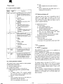
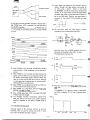
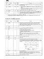
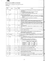
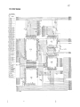
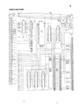
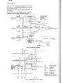
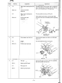
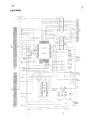
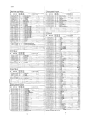
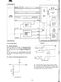
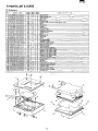
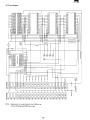
4 . Circuit Diagram
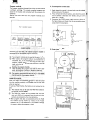
Recording paper
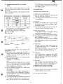
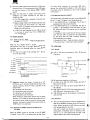
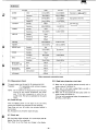
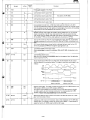
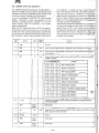
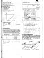
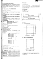
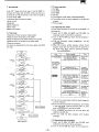
The following paper specificat ions are recommended to
meet the write and paper feed requirements of the ball
point pen .
1) Cut sh.e et
(1) Kind :
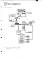
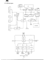
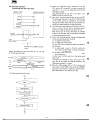
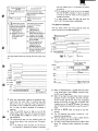
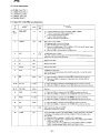
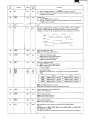
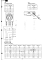
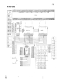
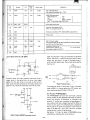
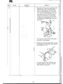
Below is a circu it diagram of the PTMPG Printer Cireuit
Board.
N~o
Pha.
Color
Carria",
Position
Detector
8
Gray
A
Yellow
Must be a high-quality paper wh ose surface smoothne$$
X -molOr
COM
Bleek
is more than 25 seconds without oil material on surface.
Movement)
0
A••
C
Plain paper
No.
.
17
I
I.
"
0-
I
White
13
<>-'
8
Blue
12
~
A
Yellow
11
0-
COM
Bl ac::k
I.
0
Ao.
0
0-
C
White
8
0-
8
Blue
7
<>-'
A
Yellow
6
~
Z-motor
(Pen-Up!
COM
Bleck
5
Down &
0
Ao.
•
0-
Color·
Chllnlilll
C
White
3
0-
0
Blue
2
~
A
Yellow
1
~
fCerriege
(3) Thickness:
60 to 110 microns (70 microns, preferable) which
equals 52 .3g/m
.
(4) Width :
Y -m otor
(Paper·
Feedlngl
A4: 210±2mm
Letter : 2 15.9±2mm (B Y..±O.078")
Paper roll : EA4AAl (A4 size paper roll)
EAl LRl (letter size paper roll)
Recommended ball point pen : specifications are as follows.
(1) Kind :
Water based
(2) Size:
¢5 x 23.3mm, +Omm, -O.l mm
(3) Life :
250m or more (when EA4ARI is USED )
(More than 43,000 characters of 96 ASC II
~haracte r
0---0""""---0
0
(2) Paper qualitY :
2
CirctJit
set of
,~
I
I
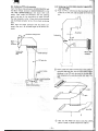
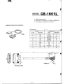
Figure VII ·2 : Circuit Difllram
2.4mm heig,t.)
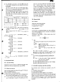
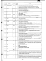
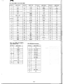
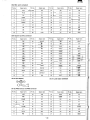
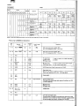
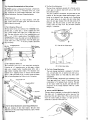
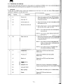
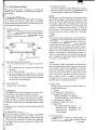
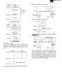
Drive pulse train
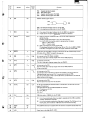
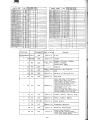
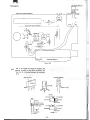
X-axis and Y-axis drive motors (1 ·2 phase excitation)
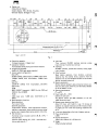
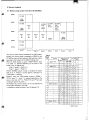
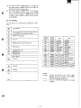
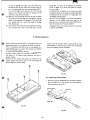
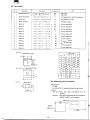
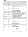
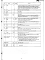
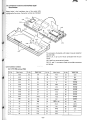
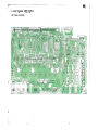
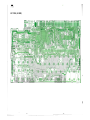
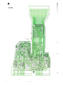
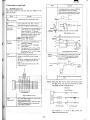
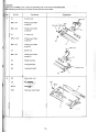
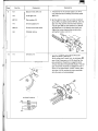
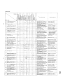
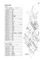
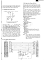
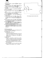
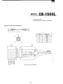
3. A Wiring Diagram
Below is a wiring diagram of the PTMPG Printer Circuit
Board.
Step No.
1
Carriage POlltlon O",,,,~
"
Z-Motor
X-Motor
r::-_ _--,c:=_ ,_ _
-;::-, Iupside)
A
ON
0
C
0
Motor
shaft
rotating
direction
MOYing direction
X .. xls
V-aldl
OFF OFF ON
2
OFF OFF OFF ON
3
OFF
ON
OFF ON
•
OFF
ON
OFF OFF
5
OFF
ON
ON OFF
6
OFF OFF
ON OFF
7
ON
OFF
ON OFF
8
ON
OFF OFF OFF
Counterclockwise
•
Clock·
wi",
•
RewfM
f.od
The X-axis motor operates under the 2·2 phase excitation
mode during initial ization.
Z·axis drive motor (2·2 phase excitation)
O'~:d(MOLEXJAPANCO
lT~:05;rl ~;t;.A,;':
Wof" 17 ';0'
.. LT D)
Step No.
8
C
0
1
ON
OFF OFF
ON
2
OFF
ON
OFF
ON
3
OFF
ON
ON OFF
•
ON
OFF
ON
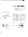
Figure VII· 1: Wiring Diagram
- 72 -
A
OFF
Mot()r II.,.ft
rotsti ng direction
direction
Counterclockw ife
Pen down
MOYing
•