1
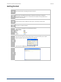
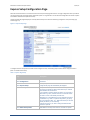
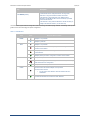
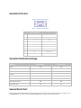
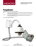
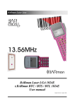
Quick Start Guide AirborneDirect™ Industrial Serial Device Server ABDG-SE-IN5410/IN5420 Revision v2.1 February 2011 Document Number: 100-8106-210 Kit Contents: Upon receiving the kit please check that you received the following: ABDG-SE-IN5410 or ABDG-SE-IN5420 Unit 2dBi, 2.4Ghz 50 ohm, omni-directional antenna Quick Start Guide 5 VDC power supply (optional, included only if ordered as an accessory) Airborne Direct software and documentation CD If any of the above contents are missing or appear damaged please contact Quatech Sales support directly at (800) 553-1170 or [email protected]. What you will need: To evaluate the unit you will need the following components and facilities: ABDG-ET-IN50X0 unit with included antenna attached. Laptop or desktop system with an Ethernet port. 5-36 VDC power for terminal block attachment, or an AC power outlet for optional ABDG-SE-IN5410/IN5420 power supply. 802.11b/g network for testing the unit, either AdHoc or Infrastructure (Access Points) mode. The test network configuration must be known. Required information will include: o SSID (Wireless network name). o Security settings (WEP, WPA, WPA2, etc.). o Security credentials (passphrase, key or certificates). o Static IP address, Subnet Mask and Gateway address if static IP addresses are used on the test network. A web browser on the laptop top or desktop (MS Explorer, Firefox, Opera and Chrome v4.0 are supported). CAT5 Ethernet cable for connecting the Airborne™ device to the laptop or desktop. Serial cable to connect Airborne™ device to host system. AirborneDirect™ Serial Device Server Quick Start Guide Quatech, Inc. Getting Started: 1 Open the AirborneDirect™ packaging and locate the Install CD. 2 Place the CD in the CD/DVD drive of the laptop or desktop you will be using to configure the AirborneDirect™ device. Follow the on screen directions for installation of the appropriate device software and documentation. 3 Connect the Ethernet cable on ABDG to an Ethernet port on the laptop or desktop system. 4 Apply power to the ABDG-SE-IN5XXX. The unit will boot and display one of the following LED patterns: 5 ABDG-SE-IN5XXX COMM: LINK : POST: POWER: Off Off Orange Blue Run the Airborne Management System application. This was installed during the CD installation and a menu item will be found in the Airborne folder located in the programs directory of your system. When the application opens the following dialog will be displayed: 6 Select Group Name: manuf and enter Group Password: dpac The AMC will load and discover the attached device. 7 100-8106-210 2 February 2011 AirborneDirect™ Serial Device Server Quick Start Guide Quatech, Inc. Right Click the Unmanaged Device then: 1. Select Change Management State 2. Select Manage OEM-Cfg1 3. Select Device OEM-Cfg1 is Factory Default 8 The devices status will move to managed and the device will be displayed under the device type/group it belongs too. Right click the device and then: 1. Select Connectivity Tools 2. Select Launch Web Browser for OEM-Cfg1 9 Opening web page shows adapter status. 10 Links to the available configuration options are identified in the left hand menu. The top menu bar provides access to different operations that can be performed by the AirborneDirect™ device. Please refer to the User’s Manual for a full description of how to use the web interface. Using Express Setup: 11 If this is the first time you have configured the device the Express Setup page will be displayed. This page provides access to the critical configuration items needed to get the ABDG up and running quickly. See Express Setup Configuration Page section for details on how to configure the device. Please refer to the User’s Manual for complete details on ABDG device configuration. 12 When the Reboot button is pressed the unit will restart and install new settings. This may take 15-20 seconds. Please refresh the web interface after the boot cycle has completed. When configured correctly the LED pattern should match the following: 13 14 100-8106-210 ABDG-SE-IN5XXX COMM: LINK : POST: POWER: No TCP Connection Off Green Green Blue TCP Connection Green Green Green Blue To use the adapter on the wireless network, address all traffic to the IP address of the wireless interface of the ABDG-SE- IN5XXX. This address is listed in the home page of the web interface. 3 February 2011 AirborneDirect™ Serial Device Server Quick Start Guide Quatech, Inc. Express Setup Configuration Page When the devices web interface is accessed for the first time an Express Setup page will be shown. This page is designed to allow a quick device set-up by presenting the most popular device configuration options in a single location. For more advanced configurations the full set of options are available in the feature links (left-hand column). The Express Setup web page will display the necessary fields based upon the selections made during configuration. The Express Setup page looks like (Figure 1): Figure 1 - Express Setup Page To configure the device for operation each field must be configured correctly. The following steps should be taken to configure the device (Note: not all fields will be visible): Table 1 - Express Page Setup Step Description Navigation Bar You will see a group of fields under the banner of WLAN Parameters. Select Configuration Feature Link Select Express Setup 100-8106-210 This step is optional. If this is the first time the device has been configured this page will automatically be displayed. Select Discovery OEM Device Name This parameter allows you to name the device uniquely or group into a functional set. When device discovery is used this name identifies the found device. If you wanted to uniquely identify the device you could mark it with a label e.g. Dev1, and then enter Dev1 in this field. When the device is found it will identify itself as Dev1. Alternately you could indicate the type of equipment the device is attached to e.g. Haas TL-2 (CNC Turning Center), by giving the unit a name like Haas_TL_2. When discovered you can then identify the device you are accessing. Enter the text string is you wish to change the default value. This field is optional. Select Radio Startup Mode Select On from the drop down menu for the radio to operate. 4 February 2011 AirborneDirect™ Serial Device Server Quick Start Guide Step Description Select Wireless LAN Connection Type If you are using Access Points make sure this is set to Infrastructure from the drop down menu. If you want to use AdHoc set this accordingly. Additional settings may be required to fully configure for AdHoc mode. Please refer to the User’s Manual for details. Select SSID Enter the name of the wireless network you wish to access. This field is case sensitive. Select Wireless LAN Security Type Select the security type the wireless network you wish to access is using. Depending upon the option you choose you may have to enter additional information. Once you have selected the security type the required inputs will be made accessible by ungraying the fields that must be completed. If the security type is not in the available selections, more are available in the WLAN Security Settings page. If you choose to use this page make sure you commit the changes you have already made before moving to the WLAN Security Settings page. Select WLAN DHCP If your WLAN network uses DHCP to assign IP addresses to the wireless clients, select Enabled from the drop down menu. If you are using static IP addresses select disabled from the drop down menu. WLAN Static IP and WLAN Subnet Mask will need to be entered. Select Ethernet DHCP If the Ethernet network connected to the Ethernet port uses DHCP to assign IP addresses to the wired clients, you should select Enabled from the drop down menu. If you are using static IP addresses you should select Disabled from the drop down menu. Ethernet Static IP and Ethernet Subnet Mask will need to be entered. Important: This field is only used if the Ethernet interface is set as a client (default for Serial devices). If set as a router the field is ignored. See the User’s Manual for a full description of configuring the unit as an Ethernet router. Select WLAN Static IP This field defines the static IP address for the wireless interface. This address is only used if the WLAN DHCP is disabled or DHCP failed. Default: 192.168.10.1 Select WLAN Subnet Mask This field defines the subnet mask used by the wireless interface. This mask is only used if the WLAN DHCP is disabled or DHCP failed. Default: 255.255.255.0 Select Ethernet Static IP This field defines the static IP address for the Ethernet interface. When configured as a serial device server (Ethernet interface is in client mode) this address is only used if the Ethernet DHCP is disabled or DHCP failed. Default: 192.168.2.100 Select Ethernet Subnet Mask This field defines the subnet mask used by the Ethernet interface. When configured as a serial device server (Ethernet interface is in client mode) this mask is only used if the Ethernet DHCP is disabled or DHCP failed. Default: 255.255.255.0 Press Commit [Button] Saves changes to the device. Optional Reloads the Express Settings page. Select this is you have further configuration options to change. Press Reload [Button] 100-8106-210 Quatech, Inc. 5 February 2011 AirborneDirect™ Serial Device Server Quick Start Guide Quatech, Inc. Step Description Optional Restarts the device. After the device as rebooted it will attempt to authenticate to the configured network. As long as the network is in range the wireless interface will connect. If the network is using DHCP then an IP address will be assigned to the WLAN interface and IP connectivity is possible over the WLAN network. If the network is using static IP addresses it will be necessary to configure the network interface, see the next step. Press Restart [Button] The web interface supports advanced configuration of the device through the additional pages available. The following sections provide guidance on how to use these pages for specific configurations. Table 2 – LED Indicators LED Color POWER Adapter is not powered. POST Airborne Device State Adapter is powered. Adapter is not powered. Adapter failed Power On Self Test (POST) and is not configured for wireless communication. Adapter passed POST but is not configured for wireless network communication. Adapter passed post and is configured for wireless communication. LINK Adapter is not powered. (Periodic Blinking) Adapter is searching for a valid network (Access Point) that matches device’s configuration. Adapter has successfully associated with an Access Point. COMM If Power LED is also Off then Adapter is not powered. If Power LED is On then: No TCP session from WLAN or Ethernet interface has been established. A TCP connection to the adapter has been established from the Wireless or Ethernet interfaces but no traffic has been detected. 100-8106-210 6 February 2011 Serial Port Pin Out Figure 2 - DE-9 Connector Pin-out Table 3 – Serial Port Pin Definition Pin RS232 (DTE) Port 1 & 2 (Default) RS422/485 1 No Connect No Connect 2 RxD RxD+ 3 TxD TxD+ 4 No Connect No Connect 5 GND GND 6 No Connect RxD- 7 RTS No Connect 8 CTS No Connect 9 No Connect TxD- Serial Port Defaults Settings: Setting Port 1 (DTE) Port 2 (DTE) BAUD 9600 9600 Parity None None Stop Bits 8 8 Data Bits 1 1 Flow Control None None Serial Default Mode Listen Listen Input Buffer Size (Bytes) 1460 1460 ON ON Serial Escape Mode Second Serial Port If you have purchased the ABDG-SE-IN5420 device it is possible to configure the second serial port using the web interface. Repeat step 10 in the Getting Started section, however select the Serial Port 2 Settings link and configure the appropriate parameters. AirborneDirect™ Serial Device Server Quick Start Guide Quatech, Inc. 5675 Hudson Industrial Parkway Hudson, OH 44236 Tel: 330.655.9000 800.553.1170 [email protected] www.quatech.com ©2010-2011 Quatech, Inc. All rights reserved. 100-8106-110G 8 4/27/2010