1
510172_r1.qxd
3/21/2001
6:25 PM
Page i
010301-510172-(01)
Cyclone Bar Code
Label Printer
(Models C-1000/C-1000P)
Users Manual
© 2001 All rights reserved.
510172_r1.qxd
3/21/2001
6:25 PM
Page ii
Notices: The information in this document is subject to change without notice.
NO WARRANTY OF ANY KIND IS MADE WITH REGARD TO THIS MATERIAL, INCLUDING, BUT
NOT LIMITED TO, THE IMPLIED WARRANTIES OF MERCHANTABILITY AND FITNESS FOR A
PARTICULAR PURPOSE. No liability is assumed for errors contained herein or for incidental or
consequential damages in connection with the furnishing, performance, or use of this material. This
document contains proprietary information which is protected by copyright. All rights are reserved.
No part of this document may be photocopied, reproduced, or translated into another language
without prior written consent.
Trademark Acknowledgments: IBM is a registered trademark of International Business
Machines Corporation. Windows is a trademark of Microsoft Corporation. All other trademarks are the
property of their respective owners. CandelaColor® Charged by Pictographics is a registered trademark
of Pictographics International Corporation.
Printing History
Edition 1.0, #010103, © Copyright 2001, All rights reserved.
FCC Compliance Statement: This device complies with part 15 of the FCC rules. Operation
is subject to the following two conditions: (1) this device may not cause harmful interference, and (2)
this device must accept any interference received, including interference that may cause undesired
operation.
For Users in the United States: This equipment has been tested and found to comply with
the limits for a Class B digital device, pursuant to Part 15 of the FCC Rules. These limits are designed
to provide reasonable protection against harmful interference in a residential installation. This
equipment generates, uses, and can radiate radio frequency energy and, if not installed and used in
accordance with the instructions, may cause harmful interference to radio communications. However,
there is no guarantee that interference will not occur in a particular installation. If this equipment does
cause harmful interference to radio or television reception, which can be determined by turning the
equipment off and on, the user is encouraged to try to correct the interference by one or more of the
following measures:
Re-orient or relocate the receiving antenna.
Increase the separation between the equipment and receiver.
Connect the equipment into an outlet on a circuit different from that to which the receiver is
connected.
Consult the dealer or an experienced radio/TV technician for help.
Use of a shielded cable is required to comply with the Class B limits of Part 15 of the FCC Rules. You
are cautioned that any changes or modifications not expressly approved in this manual could void
your authority to operate and/or obtain warranty service for this equipment.
Within the U.S., this product is intended to be supplied by a UL Listed Direct Plug-in Power Unit
marked Class 2 and rated 30 Vdc, 500 mA or 830 mA.
For Users in Canada: This digital apparatus does not exceed the Class B limits for radio noise
for digital apparatus set out on the Radio Interference Regulations of the Canadian Department of
Communications. Le present appareil numerique nemet pas de bruits radioelectriques depassant les
limites applicables aux appareils numeriques de la class B prescrites dans le Reglement sur le
brouillage radioelectrique edicte par le ministere des Communications du Canada.
CAUTION!
TO PREVENT FIRE OR SHOCK HAZARD, DO NOT EXPOSE THE UNIT TO RAIN OR MOISTURE.
TO REDUCE THE RISK OF ELECTRIC SHOCK, DO NOT REMOVE EXTERIOR PANELS. NO USERSERVICEABLE PARTS INSIDE. REFER SERVICING TO QUALIFIED SERVICE PERSONNEL. OPERATE
THE UNIT WITH ONLY THE PROPER ELECTRICAL SPECIFICATIONS AS LABELED ON THE
PRINTER AND AC ADAPTER
ii
510172_r1.qxd
3/21/2001
6:25 PM
Page iii
Table of Contents
Section 1: Getting Started
A. Choosing a Good Location...............................................................................2
B. Unpacking and Inspection ...............................................................................2
C. Identifying the Parts..........................................................................................4
D. Applying Power.................................................................................................6
E. Connecting the Printer to Your Computer .........................................6
Section 2: Loading Media
A. Loading Labels or Tags .....................................................................................9
B. Loading the Ribbon.........................................................................................11
C. Label Sensor Calibration ................................................................................13
D. Performing a Self Test .....................................................................................13
E. Resetting the Printer to Factory Default Condition ...................................14
Section 3: Using the Optical Disc Printer with Windows
A. Installing the Printer Driver...........................................................................15
B. How to Use the Driver ...................................................................................16
C. Printing Labels .................................................................................................20
Section 4: Troubleshooting and Maintenance
A. Troubleshooting ...............................................................................................21
B. Maintenance .....................................................................................................23
Appendix A: Command Language Quick Reference
A. Command Set for PPLA .................................................................................25
B. Command Set for PPLB..................................................................................31
Appendix B: Interface Specifications
A. Introduction......................................................................................................34
B. Parallel (Centronics) ........................................................................................36
C. Auto Polling ......................................................................................................36
Appendix C: ASCII Table ............................................................................................37
Appendix D: Fonts and Bar Codes for PPLA ..........................................................38
Appendix E: Fonts and Bar Codes for PPLB............................................................51
Appendix F: Specifications .........................................................................................57
Appendix G: Internal Fonts, Bar Codes and Graphics..........................................58
Index ................................................................................................................................60
iii
510172_r1.qxd
iv
3/21/2001
6:25 PM
Page iv
510172_r1.qxd
3/21/2001
6:25 PM
Page 1
Section 1: Getting Started
THANK YOU
for purchasing the Cyclone C1000/C-1000P Bar Code Label
Printer. Cyclone is a high-performance, low-cost direct
thermal/thermal transfer label printer designed for use in most
industrial, retail and office applications. Its user-friendly
design and affordable price set a new standard of excellence
for industrial-strength bar code label printers.
The printer incorporates a highly efficient memory
management technology called TrueSpeed. This feature allows
constant print speeds of 1 to 4 per second. The printer is
bundled with flexible printer driver software and a highly
capable label design program called PrimaBar for Windows®.
Together, they allow you to quickly and easily print out bar
codes, text and graphics using a standard PC running
Windows 95/98/Me/2000 and NT. A wide variety of the most
popular bar codes and 9 different fonts are also resident in the
printers internal memory for legacy applications in which a
particular programming language is required.
The solidly designed mechanism delivers long life and allows
quick and easy media and ribbon loading. Two Cyclone
models are available:
C-1000 feeds labels out the front. An integrated tear-off
bar is included.
C-1000P includes an internal rewind and peel-off
mechanism.
The internal rewind and peel-off mechanism of the C-1000P
allows dispensing of labels either out the front or one label at a
time already peeled. Backing paper is re-wound inside the
printer. This model can also rewind up to 1/3 of a roll of
printed labels inside the printer with the backing paper still
attached.
This Users Manual will help you understand basic operations
of the printer such as set-up, installation, configuration and
maintenance.
Getting Started 1
510172_r1.qxd
3/21/2001
6:25 PM
Page 2
A. CHOOSING A GOOD LOCATION
Place the printer in a location with adequate air circulation
to prevent internal heat build-up.
Do not place the printer near heat sources such as radiators
or air ducts, or in a place subject to direct sunlight,
excessive dust, mechanical vibration or shock.
Allow for adequate clearance in front of the printer to
accommodate the labels coming out of the printer.
Find a solid, flat surface with adequate room for the
printer. Make sure there is enough room to open the side
access door to change ribbons and media.
The location should be as close as possible to your PC or
terminal. Consider the distance between host and printer
for the communication cable (serial or parallel cable).
Especially for parallel cable connections, it is important to
keep the cable as short as possible.
Be sure to connect the power cord to a properly grounded
power receptacle.
B. UNPACKING AND INSPECTION
To unpack your printer:
The container should stay right side up.
Lift the printer out of the box carefully.
Remove any accessory items.
Set the printer on a solid, flat surface.
2 Getting Started
510172_r1.qxd
3/21/2001
6:25 PM
Page 3
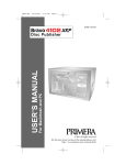
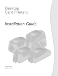
While unpacking your printer, inspect the carton to ensure that
no damage has occurred during shipping. Make sure that all
supplied accessories are included with your unit. The
following items should be included:
a.
Printer
b. CD-R with printer driver software, PrimaBar Label Design
Software for Windows 95/98/Me/2000/NT and
Operators Manual in Adobe Acrobat .pdf format. An
Adobe Acrobat Reader is also included on the CD-R.
c.
Power cord for either 100/110VAC or 220VAC
d. Extra ribbon core
e.
Starter thermal transfer ribbon
a
d
b
e
c
Save the carton and packing materials. They will come in
handy when transporting the printer.
Getting Started 3
510172_r1.qxd
3/21/2001
6:25 PM
Page 4
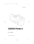
C. IDENTIFYING THE PARTS
Front Panel
The illustration below shows the printers front panel:
READY
FEED/
MEDIA
PAUSE/ CALIBR.
RIBBON
CANCEL/ RESET
CONFIG.
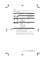
The front panel includes:
3 LED indicators (READY, MEDIA and RIBBON)
3 buttons (FEED, PAUSE and CANCEL)
LED Indicators
There are three LED indicators on the front panel labeled
READY, MEDIA and RIBBON. These indicators display
the operational status of the printer.
READY
MEDIA
RIBBON
4 Getting Started
The READY indicator will remain lit except
during the following conditions
- The printer is in PAUSE state.
- A fault condition has occurred.
The MEDIA indicator will remain lit except
when the media (labels or ribbon) has run out.
ON lit when using thermal transfer mode
with ribbon installed.
OFF not lit when in direct thermal mode (no
ribbon installed).
Blinking ribbon has run out.
510172_r1.qxd
3/21/2001
6:25 PM
Page 5
Buttons
There are three buttons on the panel; each of them has at least
two basic functions.
Under normal
condition
Button
FEED/
CONFIG.
PAUSE/
CALIBR.
CANCEL/ RESET
Important
Note:
Press the button and
turn on the power
simultaneously
Feeds a label.
Performs self test
and prints out the
configuration report.
1. Stops the printing
process.
2. Resumes printing
after button is
pressed again.
Performs media
calibration.
1. Interrupts and
deletes the current
print job.
2. Requests that the
printer start again
after an error has
been solved.
Resets the settings
at E2PROM.
It is highly suggested that you perform a media calibration
using the Pause Button as described above:
- after the first installation of labels.
- after you change to a different type or size of media
(Before calibration, the media and ribbon should be loaded
properly and the label sensor moved to the correct position).
Getting Started 5
510172_r1.qxd
3/21/2001
6:25 PM
Page 6
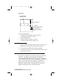
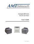
Rear Panel
External Label
Feed Slot Cover
Centronics
RS232
I
O
115
Power Slide Switch
Power Switch
Power Connector
The rear panel includes
A Centronics-type parallel connector (36-pin)
An RS-232 serial connector (9-pin)
A Power Slide Switch
A Power Switch and Power Connector
An External Label Feed Slot with Cover
D. APPLYING POWER
1.
Make sure that the Voltage Selector Switch is in the correct
position for your local power (120 VAC or 220VAC).
2.
Leave the Power Switch in the off (O) position.
3.
Connect the Power Cord to the printer and the other end to
your AC power source.
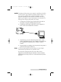
E. CONNECTING THE PRINTER TO YOUR COMPUTER
The printer is designed to be used with nearly any Windowsbased PC. Operating systems supported are Windows
95/98/Me and Windows NT/2000. The printer is equipped
with a standard 8-bit Centronics-type parallel port. This port is
used to receive data from your computer. To connect the
printer, obtain a shielded, bi-directional parallel cable. An
IEEE1194-compliant cable, not longer than 5 feet (1.5m) is
highly recommended. Then, follow these steps:
6 Getting Started
510172_r1.qxd
3/21/2001
6:25 PM
Page 7
NOTE: For fastest possible printing, your computers parallel port should be
set to ECP mode. If you experience problems with this setting or if
your computers parallel port is not ECP compatible, set your
computers parallel port to the standard LPT Printer Port setting.
Refer to your computers system documentation for instructions on
checking and/or changing the parallel port settings.
1.
Connect the Centronics-type parallel side of the cable to
the printer. Snap the fastening clips into place.
2.
Connect the other side to the back of your computer at
LPT1, LPT2 or the PARALLEL connector.
3.
Alternatively, you can connect the printer with a serial
cable to the RS232C port of your computer or terminal (for
PC compatibles, the RS232C port is COM1, COM2 or
COM3).
4.
In preparation for sending your first print job, the printers
power should now be turned on.
Note: A Centronics-type parallel connection allows for a much higher
communication speed than the use of RS232C serial.
If you use the serial port with your own cable, refer to
Appendix A and check the pin connection. Be sure that the
speed (baud rate) and protocol are consistent between printer
and host.
Getting Started 7
510172_r1.qxd
3/21/2001
6:25 PM
Page 8
The factory default parameters of the serial port are:
Speed (baud rate)
9600
Data format
1 start bit, 8 data bits and
1 stop bit.
Parity
None
Handshaking
(Flow control)
XON/XOFF as well as
RTS/CTS
Notes: 1. It is not necessary to change any switches or send any commands
for the parallel and serial port selection. The printer can
automatically detect it.
2. The default settings can also be read from the self- test page.
8 Getting Started
510172_r1.qxd
3/21/2001
6:25 PM
Page 9
Section 2: Loading Media
A. LOADING LABELS OR TAGS
1.
Open the Side Access Door by lifting it up and to the left
and open the Front Access Door by pulling it forward and
dropping it down.
Side Access Door
Front
Access
Door
2.
Open the print head module by pushing the Head Latch
toward the rear of the printer. The print head module is
spring-loaded and will automatically open as soon as the
head latch is disengaged. Also drop down the Head Latch
Support Bracket.
Label
Supply
Guide
Head Latch
Support Bracket
Outside Label Guide
Head Latch
Loading Media 9
510172_r1.qxd
3/21/2001
3.
6:25 PM
Page 10
Move the Label Supply Guide to the outside of the printer.
This allows the maximum label width to be fed through
the machine.
Label Supply Guide
Label
Supply
Spindle
Outside Label Guide
4.
Load the label roll onto the Label Supply Spindle. Make
sure the print side of the labels faces upwards when you
pull it towards the print head module. Push the roll all the
way to the inside of the printer and push the Label Supply
Guide snugly against the outside of the label roll. See
diagram above for loading labels and the diagram below
for loading tags. If using fan-fold tags, be sure to remove
the Label Feed Slot cover before loading media. Fan-fold
media must be stacked neatly behind the printer.
Label Supply Guide
Feed Slot
Label Supply Spindle
Outside Label Guide
5.
Move the Outside Label Guide to the outside of the
printer to hold the maximum label width.
6.
Inspect the label routing and verify that the path matches
the illustration in the Label Loading Diagram. Move the
Outside Label Guide inwards to keep the labels against
the inside of the printer.
7.
Check the Sensor Adjust Knob. Make sure its position is
under the gap path during printing. Adjust it inwards or
outwards if necessary.
10 Loading Media
510172_r1.qxd
3/21/2001
6:25 PM
Page 11
Sensor Adjust Knob
8.
If the ribbon is already loaded or you just want to print
with direct thermal mode, raise back the Head Latch
Support Bracket and close the print head module by
pushing downward on the Head Latch.
B. LOADING THE RIBBON
1.
Open the Side Access Door by lifting it up and to the left.
2.
Open the print head module by pushing the Head Latch
toward the rear of the printer. The print head module is
spring-loaded and will automatically open as soon as the
Head Latch is disengaged. Pull down the Head Latch
Support Bracket.
3.
Locate the Extra Ribbon Core supplied with the printer.
Place the core on the Ribbon Rewind Spindle, pushing it
all the way to the inside of the spindle.
Ribbon Rewind Spindle
Ribbon Supply Roll
Empty Core
Head Latch
Loading Media 11
510172_r1.qxd
3/21/2001
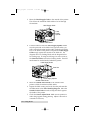
4.
6:25 PM
Page 12
Load the ribbon onto the Ribbon Supply Spindle. The
dull side of the ribbon should be facing down as it travels
through the print head module.
Ribbon Roll
Ribbon Supply Spindle
Ribbon
Rewind
Spindle
Label
Supply
Spindle
Print Head
Assembly
Head Latch
Support Bracket
Label Path
5.
Feed the leading portion of the ribbon through the Print
Head Assembly and up to the Ribbon Rewind Spindle
following the routing as shown in the diagram above. Be
sure that the ribbon travels under the black plastic ribbon
sensor.
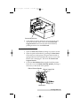
6.
To secure the ribbon on to the core, manually turn the
rewind spindle twice. You may also choose to use a small
piece of tape to hold the leading portion of the ribbons to
the ribbon core.
Tape
Ribbon Supply Roll
Head Latch
7.
If the media is already loaded, raise the Head Latch
Support Bracket and close the Head Latch by pushing
downward and close the Side Access Door.
Note: The new empty core of each subsequent roll becomes the next rewind
core.
12 Loading Media
510172_r1.qxd
3/21/2001
6:25 PM
Page 13
C. LABEL SENSOR CALIBRATION
After the ribbon and labels are loaded, it is necessary to
perform a quick calibration procedure for the label sensor.
1.
Turn off the printer. Press and hold the PAUSE button.
2.
Turn on the power.
3.
When the printer is in calibration mode, both the READY
and the MEDIA LED indicators will blink. At this point
release the button.
4.
The printer will feed the labels for 12 inches.
5.
When the READY and MEDIA LED indicators stop
blinking and remain illuminated, the calibration is
complete and the labels should feed properly between
gaps.
Note: This procedure is very important to perform upon initial installation
and every time thereafter that the media type is changed. Failure to
do so will result in the gap and label-empty detection being incorrect.
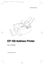
D. PERFORMING A SELF TEST
Before sending data to the printer, you may want to perform a
Self Test to confirm that the printer itself is working properly.
1.
Turn off the printer. Press and hold the FEED button.
2.
Turn on the power.
3.
The READY LED indicator will blink for few seconds.
4.
The printer will print out a configuration report.
5.
The READY LED indicator will stop blinking and stays lit.
6.
The following information will be printed on this report.
-
Font list
Hardware configuration and status
Label parameters
Firmware version
Loading Media 13
510172_r1.qxd
3/21/2001
6:25 PM
Page 14
Self Test Pattern
E. RESETTING THE PRINTER TO FACTORY DEFAULT
CONDITION
If you would like to reset the printer to its factory defaults
condition after certain commands have been sent or settings
changed:
1.
Turn off the printer. Press and hold the CANCEL button.
2.
Turn on the power.
3.
The READY LED indicator will blink for few seconds, then
release the button.
4.
The READY LED indicator will stop blinking and stays lit.
5.
The following parameters automatically reset.
- Label parameters
- Heat (Darkness)
- Speed
- Symbol set (language)
- Others various emulation settings
Notes: 1. It is necessary to perform label sensor calibration after resetting.
2. The printed label count wont be reset.
14 Loading Media
510172_r1.qxd
3/21/2001
6:25 PM
Page 15
Section 3: Using the Printer With
Windows
A. INSTALLING THE PRINTER DRIVER
The supplied Windows printer driver is used for applications
running under Windows 95/98/Me and Windows 2000/NT.
You may use any popular software application as long as it
runs under Windows and it is capable of printing to a standard
Windows printer driver.
When you use the Windows printer driver, all fonts, graphics,
bar codes and other label data are received in graphics bit-map
mode from the PC, interpreted by the printer driver, and
printed. This is the most convenient and easiest way to use the
printer and is recommended for all new applications. You will
have the full range of TrueType® fonts available to you for
printing, opening up literally thousands of possible typefaces
for your label designs. Youll also be able to use the many
powerful Windows graphics and photo editing tools that are
familiar to most computer users today. This section gives an
overview of the specific printer driver options that youll need
to know about when printing under Windows.
Under the root directory of the CD there are several subdirectories
-
WIN98/Me
WIN95
WIN2000
NT4.0
DOS
UTILITY
Select the proper directory for installation according to your
operating system.
Using the Printer with Windows 15
510172_r1.qxd
3/21/2001
6:25 PM
Page 16
Driver Installation
Start Windows.
Insert the printer driver CD-R (for Win 95/98/Me/2000 or
NT) into your CD-ROM drive.
For Windows 95/NT4.0:
- Click the Start button.
- Select Settings, then Printers
- Double click the Add Printer icon. Click Next
- Specify the Network or Local button and click the
Next button.
- Select Have Disk, enter the CD-ROM drive and path,
e.g. D:\Cyclone Drivers.
- The driver name Label Dr. 200 will appear in the
List of Printers. Click Next.
- Select your desired operating system, e.g. WIN98.
Click OK.
- Click OK again if necessary.
- Select the communication port for the label printer. For
select "LPT1:", "LPT2:" or "LPT3", for serial port select
"COM1:" or "COM2:".
- After the related files have been copied to your system,
the procedure is complete.
- If you need to print from the label printer you should
set "Label Dr. 200" as the Default Printer.
Note: If you are just updating your driver, make sure to delete the previous
version first.
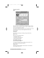
B. HOW TO USE THE DRIVER
After the driver is installed, you can open the Label Dr. 200
dialogue box and make parameter settings through the same
paths as mentioned above:
1.
Windows 95/NT4.0 - Start > Settings > Printers > Label Dr.
> Properties
16 Using the Printer with Windows
510172_r1.qxd
3/21/2001
6:25 PM
Page 17
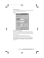
Parameter setting:
After entering the Label Dr. 200 you can change the parameters
to meet your configuration and needs.
Details
Print to the following port
This allows you to select the IO port to link with the printer.
The port may be parallel (LPT or ECP), serial COM), network
port or file. In most cases you should select ECP if it available.
If not, select LPT.
If the communication port you select is serial (not
recommended due to slow data transfer rates), COM1: or
COM2:, check the baud rate and flow control as they must be
consistent between host and printer. The printers baud rate
can be read from the self-test page. The factory default baud
rate is 9600.
Using the Printer with Windows 17
510172_r1.qxd
3/21/2001
6:25 PM
Page 18
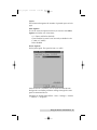
Using the Label Dr.
Paper
Select the paper size appropriate to the labels or tags you have
installed. In most cases, it is easiest to select Custom and enter
your own label height and width.
Or, select the label size from the list of pre-formatted sizes. The
selected label size may be a little higher than that of the
physical label.
Orientation
Set portrait or landscape according to the print direction.
Paper source
Select one of the following items:
T/T & Media with Gap
T/T & Media with Black Line
T/T & Continuous Media
D/T & Media with Gap
D/T & Media with Black Line
D/T & Continuous Media
T/T stands for thermal transfer (ribbon) mode and D/T for
direct thermal mode (without ribbon).
Media choice
Set the heat value or darkness from this field. The darkness
value ranges from 0 to 15.
18 Using the Printer with Windows
510172_r1.qxd
3/21/2001
6:25 PM
Page 19
Copies
This selection designates the number of printed copies of each
page.
More Options
To use the cutter and peeler function you need to enter More
Options and select one of the items:
w/o Cutter and Peeler (default)
Cutter Enabled (a cutter is not currently available for the
C-1000 or C-1000P)
Peeler Enabled
Device Options
Set the print speed. The speed is from 1 to 4 IPS.
After the driver is installed, you can open the Label Dr. 200
dialogue box and make parameter settings through the same
paths as mentioned above:
Windows 95/98/Me/2000/NT4.0 - Start > Settings > Printers
> Label Dr. > Properties
Using the Printer with Windows 19
510172_r1.qxd
3/21/2001
6:25 PM
Page 20
C. PRINTING LABELS
Now that you have hooked up your printer, loaded the labels
or tags and ribbon, and installed the printer driver software,
you are ready to print your first labels.
1.
Go to your Windows-based label design program or install
and launch the software included with your printer called
PrimaBar for Windows.
2.
Open or create the label file you wish to print.
3.
Once you have opened or created the label you wish to
print, select Print Setup (or the equivalent) from the
programs File menu to verify that the printer driver
settings are correct for your label size and print file. Be
sure that the proper parameters such as speed, label gap
setting and heat settings are correct for your type of media.
Once these settings are correct, selet Print from the
programs File menu. Enter the number of labels you wish
to print in the Copies box.
4.
The printer driver will begin to process your job.
Depending upon the size of the image, the speed of your
PCs processor and the amount of RAM you have in your
PC, processing time can be either immediate or take
several seconds.
5.
Once processing is complete, the printer will begin to print.
Print time depends upon the Print Speed selection you
made in the Label Dr. 200 settings.
Congratulations! If everything has been done properly, you
should have by now printed your first labels. Consult the
remaining chapters of this manual for information on troubleshooting, maintenance and connecting the printer to legacy
systems.
20 Using the Printer with Windows
510172_r1.qxd
3/21/2001
6:25 PM
Page 21
Section 4: Troubleshooting &
Maintenance
A. TROUBLESHOOTING
Generally, when a malfunction or an abnormal condition
occurs, the READY LED will keep blinking and printing and
communication between the host and printer will stop.
After the problems have been solved, press CANCEL to
continue printing.
Problems with media
Blinking Indicators
Possible
Problems
READY and MEDIA
Solutions
Remarks
Missing gap
Check the media
path
Check the
position of
label sensor.
If you use continuous
media, check your
application software
and driver.
You should select
Continuous.
Media out
Supply the media
roll
Media not
installed
Install the media
roll
Media jam
Fix the jam
If everything is OK, perform a label sensor calibration.
Troubleshooting and Maintenance 21
510172_r1.qxd
3/21/2001
6:25 PM
Page 22
Problems with ribbon
Blinking Indicators
Possible
Problems
READY and RIBBON
Solutions
Remarks
Ribbon has
run out
Install a new ribbon
Does not apply to
direct thermal.
Ribbon jam
Fix the jam
Not for direct
thermal.
Ribbon
sensor error
Replace the ribbon
sensor
Not for direct
thermal.
Other problems
Blinking Indicator
Possible
Problems
READY
Solutions
Remarks
SERIAL IO
ERROR
Inconsistent baud
rate, format or
protocol between
host and printer
Check bits 6 ~ 8 of
DIP switch. Refer to
section 2 for DIP
switch.
Not for Centronics
MEMORY
FULL
Check the graphics
and soft fonts from
host.
Make sure to delete
the graphics and soft
fonts if they are no
longer used by the
application software.
22 Troubleshooting and Maintenance
510172_r1.qxd
3/21/2001
6:25 PM
Page 23
Miscellaneous other problems
The data has been sent, but there is no output from the
printer.
- Check the active printer driver, it should be Label Dr.
200 for your Windows system and the label printer.
- Check the emulation and the print (command) file.
Vertical streaks in the printout usually indicate a dirty or
faulty print head.
- Clean the print head first, if they still persist, replace
the print head.
Unstable ribbon roll rotation.
- Check the label path and make sure the head latch is
securely closed.
Poor printout quality.
- The ribbon may be not qualified.
- The media may be not qualified.
- Adjust the Darkness (heat temperature).
- Slow down the print speed.
Recovery
In order to continue your print jobs after any abnormal
conditions have been fixed, simply press the CANCEL button
to restart the printer. Make sure that the LED indicators are
illuminated and not blinking and remember to re-send your
files.
B. MAINTENANCE
Before maintenance be sure to turn off the printer power.
1.
Cleaning the thermal print head
Turn off the printer, open the cover, print head module and
remove the ribbon. Rub the print head with a cotton swab
that has been moistened with isopropyl alcohol. Check for
any traces of black color or adhesive on the cotton after
cleaning. Repeat if necessary until the cotton swab is clean
after it is passed over the head. Many commercially
available print head cleaning kits are also available.
Note: The print head should be cleaned at least every time the ribbon is
replaced and more often depending on actual usage and conditions.
Troubleshooting and Maintenance 23
510172_r1.qxd
3/21/2001
2.
6:25 PM
Page 24
Cleaning the roller
Using a cotton swab moistened with isopropyl alcohol,
clean the roller so that no residue from label adhesive is
visible.
Note: The roller should be cleaned whenever you notice a build-up of dust
or label adhesives.
3.
Cleaning the media compartment
Clean the media compartment with a soft cloth moistened
with a mild detergent.
Every time a media roll is printed this compartment
should be cleaned to reduce the incidence of dust, which
can affect print quality.
24 Troubleshooting and Maintenance
510172_r1.qxd
3/21/2001
6:25 PM
Page 25
Appendix A: Command Language
Quick Reference
This section lists all internal software commands for the printer
if you are installing it in a legacy application in which a
specific printer programming language is being used. For
more information please refer to the Programmers Manual,
available separately from the factory or your Authorized
Reseller. This section does not apply if you are using the
printer with the included Windows-compatible driver and
Windows application software.
A. COMMAND SET FOR PPLA
The following commands are for Printer Programming
Language A.
System Setting Commands
These commands will cause related parameters to be saved in
the permanent storage, E2PROM. The parameters will be
stored unless they are changed by commands or a reset from
the front panel.
Command
Description
Parameter
Factory default
<STX>KI4n
Media empty
check
n: 0 - disable
1 - enable.
enabled
<STX>KI7n
Set ribbon
mode
n: 0 DT,
1 TT.
TT with ribbon
<STX>KI8n
Set baud rate
m: 0 9600,
1 600,
2 2400,
3 19200,
4 4800,
5 38400,
6 1200,
7 9600.
9600 baud.
<STX>KI;1
Select alternate
Control codes
!KI;0 - selects
standard
control
codes.
<STX>KXnnnn
Set continuous
label length
nnnn: a 4-digit
number,
in mm
Valid under
Windows driver
Label Dr.
Command Language Quick Reference 25
510172_r1.qxd
3/21/2001
6:25 PM
Page 26
(Table continued from previous page)
Command
Description
Parameter
<STX>KI<m
Set symbol set
for ASD smooth
font set
m: 0 - USASCII, 0 for USASCII
1 - United
Kingdom,
2 - Spanish,
3 - Swedish,
4 - French,
5 - German,
6 - Italian,
7 - Danish/
Norwegian.
Factory default
Interaction Commands
These commands only apply to the serial port and allow the
host to understand the status and configuration of the printer.
Command
Description
Response
Contents
<SOH>#
Reset
Y
<XOFF><XON>T
<SOH>A
Send a readable
status string
Y
<8 bytes, Y/N> <CR>
byte 1 : Y - printer busy
byte 2 : Y - paper out
byte 3 : Y - ribbon out
byte 4 : N (always)
byte 5 : Y - printing
byte 6 : Y - printer
paused
byte 7 : Y - label
presented
byte 8 : N (always)
<SOH>B
Toggle pause
condition
N
<SOH>E
Send the
number of
labels to be
printed
Y
e. g.
0000<CR>
no label left to be
printed
<SOH>F
Send status byte
Y
n<CR>
same as <SOH>A,
except bit 1 ~ 8 are
corresponding to byte
1 ~ 8 of <SOH>A.
26 Command Language Quick Reference
510172_r1.qxd
3/21/2001
6:25 PM
Page 27
Note: Control codes for the printer commands.
Symbol
Code (hexadecimal)
XON
XOFF
STX
SOH
ESC
LF
CR
11H
13H
02H
01H
1BH
0AH
0DH
Note: There is no space code in each command.
System Level Commands
Command
Description
<STX>a
Enable page/job
echo characters
<STX>cxxxx
Set continuous
paper length and
disable edge sensor
<STX>Dxxxxxxx
Memory dump**
<STX>Exxxx
Set copy count for
stored label
<STX>e
Enable edge sensor
<STX>F
Feed a page
<STX>fxxx
Back feed from top
position
<STX>G
Print stored label
<STX>I
Download graphics
<STX>J
Set pause for each
label
<STX>j
Cancel pause
<STX>KQ
System configuration
details
<STX>L
Enter label formatting
state
<STX>Mxxxx
Set maximum label
length
<STX>m
Set measurement in
metric
<STX>n
Set measurement in
inches
Remarks
xxxxxxx : memory
address in HEX value
either PCX, BMP, PCX
or HEX format
Command Language Quick Reference 27
510172_r1.qxd
3/21/2001
6:25 PM
Page 28
(Table continued from previous page)
Command
Description
<STX>Oxxxx
Set start of print
position
<STX>P
Enable data dump
<STX>Q
Clear memory
(fonts & graphics)
<STX>r
Select reflective sensor
<STX>Sn
Set feed rate for motor
<STX>T
Print test pattern
<STX>Vn
Set cutter or dispenser
configuration
<STX>v
Printer version
information
<STX>Wn
Graphics/fonts/labels
and memory status
details
<STX>x
Release file from
printer memory
Remarks
n: A, B or C
n: 1 - enable cutter,
4 - enable dispenser
n: G, F or L.
through RS232
Formatting Commands
Command
Description
:xxxx
Set cut amount
An
Set print mode
n : 1- exclusive, 2 - transparent
Cxxxx
Set horizontal offset
cxx
Set cut amount
Dwh
Set pixel width and height
E
Form feed and return to system level
command mode
G
Store previous data to global register
<STX>Sn
Retrieve from global register. n : global
register ID
Hxx
Set heating value, xx=01~20
M
Toggle the mirror mode
m
Set measurement in metric
n
Set measurement in inches
Pn
Set print speed. n=A, B, or C **
Qxxxx
Set copy count
28 Command Language Quick Reference
510172_r1.qxd
3/21/2001
6:25 PM
Page 29
(Table continued from previous page)
Command
Description
Rxxxx
Set vertical offset
r<n..n>
Retrieve label data from printer buffer.
<n..n> : label name
sm<n..n>
Save label data to printer buffer.
m : memory module, <n..n> : label name
Txx
Set end-of-line code, xx : hex value
z
Change slash zero to normal zero (0).
+xx
>xx
Make auto increment for numeric or
alphanumeric,
xx : count
-xx
<xx
Make auto decrement for numeric or
alphanumeric,
xx : count
^xx
Set count amount, xx : count
Notes: 1. The formatting and editing commands should be grouped
together, leaded by <STX>L and ended by E command
**: The parameter ranges from A to E (1 ~ 4 ips)
Editing Commands
Commands
Description
rthveeeyyyyxxxx<string><CR> general format
r: print direction
1,2,3 or 4 (rotation)
t: object type
0 ~ 9 and : (fonts) **,
A ~ Z and a ~ z (bar codes),
X (lines or boxes),
Y (graphics).
h: width multiplier
1 ~ 9 and A ~ O.
0 stands for default.
v: height multiplier
1 ~ 9 and A ~ O,
0 stands for default.
eee: bar code height
This is ignored for box, line and
graphics. It represents point size for
font 9 and symbol set for Courier
font**.
yyyy: Y coordinate
xxxx: X coordinate
<string>: depends on
object types
Command Language Quick Reference 29
510172_r1.qxd
3/21/2001
6:25 PM
Page 30
Object
String
Description
L : line
(if t is X)
Lwwwhhh
www : width,
hhh : height.
L : line
(if t is X)
Lwwwwhhhh
wwww : width,
hhhh : height.
B : box (if t is X)
Baaabbbcccddd
aaa : horizontal width
bbb : vertical height
ccc : thickness of top
and bottom
edges
ddd : thickness of left
and right bars
B : box(if t is X)
Baaaavvvvccccdddd
aaaa : horizontal width
vvvv : vertical height
cccc : thickness of top
and bottom edges
dddd : thickness of left
and right bars
Bar code
(if t is in the
range A ~ Z
or a ~ z)
bar code data
The bar codes (and
human readable text)
will be printed
according to the
selected bar code type
(A ~ Z or a ~ z).
Text
(if t is in the
range 0 ~ 9)
text data
Such text data will be
printed according to the
selected font (0 ~ 9).
file name
If t is Y and the file
was downloaded by
<STX>I command.
Font Downloading Commands
The following commands are only used for soft fonts with PCL
format.
Command
Description
ESC*c###D
assign the soft fonts ID number
(### : 100 ~ 999)
ESC)s###W
Download font descriptor
(### : length of font descriptor)
ESC*c###E
set character code (### : 1 ~ 255)
ESC(s###W
Download character descriptor and image
(### : length of character descriptor and
image)
30 Command Language Quick Reference
510172_r1.qxd
3/21/2001
6:25 PM
Page 31
B. COMMAND SET FOR PPLB
The following commands are for Printer Programming
Language B.
All PPLB commands must be ended with <LF> or <CR>+<LF>
codes. No spaces are allowed between parameters and leading
command character.
Command
Description
Ax,y,rot,font,hm,
vm,nr,string
Print text.
Bx,y,rot,bar,nw,
ww,v,hum,string
bx,y,type,[
]
Ccn,dn,just,step,string
Dp1
EI
Ekstring
ESstring,
.
FE
FI
Fkstring
Fsstring
Fsstring
GGx,y,string
GI
Gkstring
GMstring,size<LF>
Parameter
font: 1 ~ 5 for internal
font and A ~ Z
for soft font.
Print Bar Code.
nw: width of narrow
bar: barcode selection
bar
ww: width of wide bar
v:
bar code height
hum: B for printing
readable code and
N for disabling.
Print 2D Bar Code
type: M for Maxi code
and P for PDF 417
Counter declaration cn:
counter index
dn:
digit number
just: L,R,C and N for
field justification
step: step value
Heat setting
p1:
density, 0 ~ 15
Print soft font names
Delete soft font
string: soft font name or
* to delete all
soft fonts
Download soft font
End form store
Print form names
Delete form
string: form name or *
to delete all forms
Execute form
string: form name
Save form
string: form name
Print graphics
string: graphic name
Print graphic list
Delete graphics
string: graphic name or
* to delete all
graphics
Store graphics
string: graphic name
size: graphic size
in byte
Command Language Quick Reference 31
510172_r1.qxd
3/21/2001
6:25 PM
Page 32
(Table continued from previous page)
Command
Description
Parameter
Ip1,p2,001
Select symbol set**
p1:
p2:
JB
JF
LEx,y,hlen,vlen
Disable back feed**
Enable back feed**
Line draw by
exclusive
Line draw by OR
Draw white line
Clear frame buffer
Select options
Print label
LOx,y,hlen,vlen
LWx,y,hlen,vlen
N
O[,C][,N][,D]
Pp1[,p2]
hlen: horizontal length
vlen: vertical length
p1:
p2:
label set number
copy number of
each label
p1:
p2:
p3:
w:
label length
gap length
offset length
label width
PAp1[,p2]
Qp1,p2[,+p3]
Print automatic
Set label and
gap length**
Qw
Rx,y
Sp1
U
UN
US
Vvn,dn,just,string
Set label width**
Set origin point**
Set print speed
p1:
Print configuration
Disable Error Report
Enable Error Report
Define variable
vn:
dn:
just:
Xx,y,thick,ex,ey
Draw box
ZT
ZB
ZS
ZN
?
Set print direction
d1,hadj
d2,hadj
Enable/disable
store-to-Flash++
Download variables
or counters
Set horizontal position adjustment**
Set horizontal
position
adjustment
32 Command Language Quick Reference
7 or 8 data bits
symbol set
speed value, 2~4
variable index
digit number
L,R,C and N
for field
justification
ex, ey: end position
thick: line
thickness
ZS: print from top
ZB: print from bottom
power-on default is
ZN(disabled)
hadj: adjustment in
dots.
same as d1, except it is
no saved to E2PROM
510172_r1.qxd
3/21/2001
6:25 PM
Page 33
Notes: 1.
2.
3.
4.
5.
6.
x and y stand for horizontal and vertical coordinate values.
hm and vm stand for horizontal and vertical multipliers.
rot is the rotation direction, its value is from 0 ~ 3.
nr is either N for normal printing or R for reverse printing.
string is bracket by double quote marks, e.g. text.
** Such commands will cause the printer to save parameters to
permanent storage(E2PROM).
7. ZS takes effect only if optional flash memory board is installed.
Ap
Command Language Quick Reference 33
510172_r1.qxd
3/21/2001
6:25 PM
Page 34
Appendix B: Interface Specifications
A. INTRODUCTION
This section details the interface specifications of I/O ports for
the printer. These specifications include pin assignments,
protocols and detailed information about how to properly
interface your printer with your host or terminal.
Serial
The RS232 connector on the printer side is a female DB-9.
Pin
Direction
Definition
1
In
DSR
2
In
RxData
3
Out
TxData
5
-
Ground
6
Out
DTR
7
Out
RTS
8
In
CTS
9
Out
+5V
Note: Pin 9 is reserved for factory use only. Do not connect this pin if you
are using a general host like a PC.
Connection with host:
Host 25S
Printer 9P
(PC or compatible)
Host 9S
Printer 9P
(PC or compatible)
DTR 20 ....................1 DSR
DTR 4 .......................1 DSR
DSR 6 ......................6 DTR
DSR 6........................6 DTR
TX 2 .........................2 RX
TX 3 ..........................2 RX
RX 3 .........................3 TX
RX 2 ..........................3 TX
CTS 5.......................7 RTS
CTS 8 ........................7 RTS
RTS 4 .......................8 CTR
RTS 7.........................8 CTS
GND 7.....................5 GND
GND 5 ......................5 GND
34 Interface Specifications
510172_r1.qxd
3/21/2001
6:25 PM
Page 35
Alternatively you can just connect the 3 wires in the following
way.
Host 25S
Printer 9P
(PC or compatible)
Host 9S
Printer 9P
(PC or compatible)
TX 2 .........................2 RX
TX 3 ..........................2 RX
RX 3 .........................3 TX
RX 2 ..........................3 TX
GND 7.....................5 GND
GND 5 ......................5 GND
pin 4
pin 4
pin 5
pin 6
pin 6
pin 7
pin 20
pin 8
The most simple way to connect to other hosts (not PC
compatible) or terminals is:
Printer
Terminal/Host
Pin 2- RxData......................TxData
Pin 3- TxData......................RxData
Pin 5- Ground.....................Ground
In general as long as the data quantity is not too large or you
use Xon/Xoff as flow control, there will be no problem at all.
Baud rate:
2400, 4800, 9600, 19200 and 38400.
Data format:
always 8 data bits, 1 start bit and 1 stop bit.
Parity :
always non parity
Handshaking :
XON/XOFF as well as CTS/RTS (hardware
flow control).
If you run an application with the bundled printer driver
under Windows and use the serial port, you should check the
above parameters and set the flow control to Xon/Xoff or
hardware. However, a parallel connection is HIGHLY
RECOMMENDED for connection to a Windows-based PC for
best performance.
Interface Specifications 35
510172_r1.qxd
3/21/2001
6:25 PM
Page 36
B. PARALLEL (CENTRONICS)
The parallel port is a standard 36-pin Centronics-type
connection. Its pin assignments are listed as following.
Pin
Direction
Definition
Pin
1
In
/STROBE
13
2
In
Data 1
14,15
3
In
Data 2
16
-
Ground
4
In
Data 3
17
-
Ground
5
In
Data 4
18
6
In
Data 5
19~30
7
In
Data 6
31
8
In
Data 7
32
Out
/Fault
9
In
Data 8
33~36
-
NC
10
Out
/ACK
11
Out
BUSY
12
Out
PE
Direction
Out
Definition
SELECT
NC
NC
-
Ground
NC
C. AUTO POLLING
Both the serial and parallel ports are active at the same time on
this printer, so data can be received on either one, however no
provision is made for port contention. If data is transmitted to
both ports simultaneously, it will cause the data in the received
buffer to be corrupted.
36 Interface Specifications
510172_r1.qxd
3/21/2001
6:25 PM
Page 37
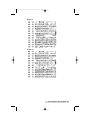
Appendix C: ASCII Table
0
0 NUL
1 SOH
2 STX
3
4
5
6 ACK
7 BEL
8
BS
9
A LF
B
C
FF
D CR
E
SO
F
SI
1
2
XON
!
#
$
%
&
(
)
*
+
,
.
/
XOFF
NAK
ESC
RS
US
3
0
1
2
3
4
5
6
7
8
9
:
;
<
=
>
?
4
@
A
B
C
D
E
F
G
H
I
J
K
L
M
N
O
5
P
Q
R
S
T
U
V
W
X
Y
Z
[
\
]
^
_
6
`
a
b
c
d
e
f
g
h
i
j
k
l
m
n
o
7
p
q
r
s
t
u
v
w
x
y
z
{
|
}
~
DEL
ASCII Table 37
510172_r1.qxd
3/21/2001
6:25 PM
Page 38
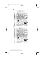
Appendix D: Fonts and Bar Codes
for PPLA
Internal Fonts
Fonts 0 ~ 8 have single symbol set.
Font 0
Font 2
Font 3
38 Fonts and Bar Codes for PPLA
Font 1
510172_r1.qxd
3/21/2001
6:25 PM
Page 39
Font 4
Font 5
Fonts and Bar Codes for PPLA 39
510172_r1.qxd
3/21/2001
6:25 PM
Page 40
Font 6
Font 7
Font 8
40 Fonts and Bar Codes for PPLA
510172_r1.qxd
3/21/2001
6:25 PM
Page 41
Font 9
Font 9 (ASD smooth font set) includes 8 symbol sets, USASCII,
UK, German, French, Italian, Spanish, Swedish, and
Danish/Norwegian.
The sizes are 6, 8, 10, 12, 14 and 18 points.
4 points
6 points
8 points
10 points
Fonts and Bar Codes for PPLA 41
510172_r1.qxd
3/21/2001
6:25 PM
Page 42
12 points
14 points
18 points
42 Fonts and Bar Codes for PPLA
510172_r1.qxd
3/21/2001
6:25 PM
Page 43
Roman-8
ECMA-94
Fonts and Bar Codes for PPLA 43
510172_r1.qxd
3/21/2001
6:25 PM
Page 44
PC
PC-A
44 Fonts and Bar Codes for PPLA
510172_r1.qxd
3/21/2001
6:25 PM
Page 45
PC-B
Legal
Fonts and Bar Codes for PPLA 45
510172_r1.qxd
3/21/2001
6:25 PM
Page 46
Greek
Russian
46 Fonts and Bar Codes for PPLA
510172_r1.qxd
3/21/2001
6:25 PM
Page 47
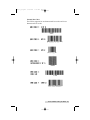
Internal Bar Codes
This PPLA supports 20 one dimensional bar codes and 2 two
dimensional bar codes.
Fonts and Bar Codes for PPLA 47
510172_r1.qxd
3/21/2001
6:25 PM
Page 48
48 Fonts and Bar Codes for PPLA
510172_r1.qxd
3/21/2001
6:25 PM
Page 49
Fonts and Bar Codes for PPLA 49
510172_r1.qxd
3/21/2001
6:25 PM
Page 50
50 Fonts and Bar Codes for PPLA
510172_r1.qxd
3/21/2001
6:25 PM
Page 51
Appendix E: Fonts and Bar Codes
for PPLB
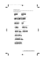
Internal Fonts
There are 5 internal fonts for the PPLB emulation.
Each has 6 eight-bit and 9 seven-bit symbol sets. Font 5 does
not contain any lower-case characters.
8 bit symbol sets
code page 437, 850, 852, 860, 863 and 865
7 bit symbol sets
USA, British, German, French, Danish,
Italian, Spanish, Swedish and Swiss
Font 1
Font 2
Font 3
Font 4
Font 5
Fonts and Bar Codes for PPLB 51
510172_r1.qxd
3/21/2001
6:25 PM
Page 52
Symbol Set
52 Fonts and Bar Codes for PPLB
510172_r1.qxd
3/21/2001
6:25 PM
Page 53
Fonts and Bar Codes for PPLB 53
510172_r1.qxd
3/21/2001
6:25 PM
Page 54
54 Fonts and Bar Codes for PPLB
510172_r1.qxd
3/21/2001
6:25 PM
Page 55
Internal Bar Codes
The PPLB supports 26 one-dimensional bar codes and 2 two
dimensional bar codes.
Fonts and Bar Codes for PPLB 55
510172_r1.qxd
3/21/2001
6:25 PM
Page 56
56 Fonts and Bar Codes for PPLB
510172_r1.qxd
3/21/2001
6:25 PM
Page 57
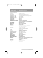
Appendix F: Specifications
Printer Specifications
Resolution
203 DPI (8 dots/mm)
Print method
Direct thermal and thermal transfer
Maximum print speed
1 to 4 inches (25.4mm to 101.6mm) per second
Maximum print width
4.09 in (104mm)
Maximum print length
45 in. (1143 mm)
Onboard RAM
512K bytes
Onboard Flash
512K bytes
Maximum label roll diameter
8 in.(203 mm) outside diameter
1.5 in. to 3.0 in.(38 mm to 76 mm) inside diameter
Label indexing
Black stripe and gap
Ribbon types
Wax, Wax/Resin and Resin
Ribbon size
OD 3 in. (75mm)
ID 1 in. (25mm)
IO Interface
RS-232 serial and Centronics parallel ports
Auto- polling for both ports.
Dimension
9.8"W x 16"D x 10.2"H
(250mmW x 410mmD x 260mmH)
Weight
26.8 lbs. (12kg)
Electrical
CE, UL, CUL, FCC class A
110/220 VAC +10%, 50/60 Hz
Operating temperature
40° to 140°F (4° to 38°C)
Storage temperature
-40° to 140°F (-40° to 60°C)
Humidity
15 to 85% RH
Windows driver
Win 95, 98, 2000 and NT
Printer emulation
PPLA or PPLB
Firmware management
Upgradeable from PC
Media type
Roll-feed, die-cut, continuous, fan-fold, tags, ticket
in thermal paper or plain paper.
Front panel
3 buttons
3 LED indicators
Rear panel
Parallel and serial I/F
Power switch
Specifications 57
510172_r1.qxd
3/21/2001
6:25 PM
Page 58
Appendix G: Specifications for
Internal Fonts, Bar
Codes and Graphics
NOTE: If you are connecting your printer to a Windows-based PC, this
section does not apply. However, if you are connecting the printer to
a host-based system using a "legacy" programming language, this
section will be useful in understanding how to make the printer
compatible using one of the two built-in programming languages.
Two distinct printer programming languages - PPLA and PPLB
- are built into Cyclone. Each has a different definition for
fonts, barcodes and graphics. These programming languages
enable your host to communicate with the label printer and
perform many functions.
Printer Programming Language A, PPLA
Specification
General fonts
7 alpha-numeric fonts, OCR A and
OCR B
ASD smooth fonts
6, 8, 10, 12, 14 and 18 points
Symbol sets for smooth fonts
USASCII, UK, German, French,
Italian, Spanish, Swedish, and
Danish/Norwegian
Courier fonts
8 symbol sets (PC, PC-A, PC-B,
EAMA-94, Roman , Legal, Greek and
Russian)
Soft fonts
Downloadable PCL fonts
Font expandability
1x1 to 24x24
Bar code types
Code 39, Code 93, Code 128/subset
A,B,C, Codabar, Interleave 2 of 5,
UPC A/E/2 and 5 add-on,
EAN-8/13, UCC/EAN-128, Postnet,
Plessey, HBIC, Telepen and FIM.
MaxiCode and PDF417
(2D symbologies).
Graphics
PCX, BMP, IMG and HEX formats
58 Internal Fonts, Bar Codes and Graphics
510172_r1.qxd
3/21/2001
6:25 PM
Page 59
Printer Programming Language B, PPLB
Specification
General fonts
5 fonts with different point sizes
Symbol sets (Code pages)
8 bits: code page 437, 850, 852, 860,
863 and 865.
7 bits: USA, British, German, French,
Danish, Italian, Spanish, Swedish and
Swiss.
Soft fonts
Downloadable soft fonts
Font expandability
1x1 to 24x24
Bar code types
Code 39(checksum), Code 93,
Code 128/subset A,B,C, Codabar,
Interleave 2 of 5(checksum),
Matrix 25, UPC A/E 2 and 5 add-on,
EAN-8/13, Code 128UCC,
UCC/EAN, Postnet, German
Postcode. MaxiCode and PDF417
(2D symbologies).
Graphics
PCX and binary raster
Internal Fonts, Bar Codes and Graphics 59
510172_r1.qxd
3/21/2001
6:25 PM
Page 60
Index
Bar Codes ................................................................47-50,55-56,58-59
Buttons.................................................................................................5
Cables................................................................................................6,7
Calibration, Media .......................................................................5,13
Connecting Printer ............................................................................6
Connectors, Rear Panel.....................................................................6
Controls, Front Panel ........................................................................4
Controls, Rear Panel..........................................................................6
Errors ............................................................................................21-23
Fan-Fold Media, Loading ...............................................................10
Indicator Lights (LED)......................................................................4
Labels, Loading ............................................................................9-11
Maintenance................................................................................23-24
Parallel Data Connection ..............................................................6,7
Power....................................................................................................6
PPLA Command Set ..................................................................25-30
PPLB Command Set........................................................................33
Printer Driver, Installing and Using ......................................15-19
Printing Labels.................................................................................20
Resetting the Printer ....................................................................5,14
Ribbons, Loading .......................................................................11,12
Rollers, Cleaning .............................................................................24
Self-Test ..........................................................................................5,13
Sensor Adjustment.....................................................................10,11
Serial Data Connection .................................................................6,7
Specifications, Interfaces..........................................................34-36
Specifications, Printer.....................................................................57
Thermal Print Head ........................................................................23
Troubleshooting .........................................................................21-23
Unpacking........................................................................................2,3
60 Index
510172_r1.qxd
3/21/2001
6:25 PM
Page 61
510172_r1.qxd
3/21/2001
6:25 PM
Page 62
Printed in the United States of America
P/N 510172