1
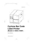
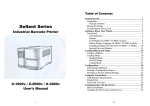
Fastmark 4000 Series
Barcode Label Printer
User’s Guide
Part No. 110121 A
IMPORTANT SAFETY INSTRUCTIONS
AND OTHER NOTICES
n
This label printer complies with the requirements in Part 15 of FCC rules for a Class A
computing device. Operation of this equipment in a residential area may cause
unacceptable interface to radio and TV reception, requiring the operator to take whatever
steps are necessary to correct the interference.
n
Place the printer on a flat, firm and solid surface.
n
Do not place the printer near a heat source or near water.
n
Refer to the specification label on the bottom of this printer and ensure that your power
source exactly meets these requirements.
n
Do not open the printer during operation to avoid electrical shock.
n
Do not attempt to disassemble this printer if it malfunctions.
n
All rights are reserved. No part of this document may be reproduced or issued to third
parties in any form without the permission of AMT Datasouth.
n
The material in this document is provided for general information and is subject to change
without notice.
TRADEMARK CREDITS
PCL is a registered trademark of Hewlett-Packard Company
Windows, MS-Word and MS-DOS are registered trademarks of Microsoft Corporation
PC is a registered trademark of International Business Machines
Centronics is a registered trademark of Centronics Corporation
CodeSoft is a registered trademark of Techniques Avancees
BarTender is a registered trademark of Seagull Scientific Systems, Inc.
LabelView is a registered trademark of Techniques Avancees
LabelMatrix is a registered trademark of StrandWare, Inc
User's Guide
1
CONVENTIONS
Some of the procedures in this guide contain special notices that highlight important
information:
Note
Indicate information that you should know to help your
printer run properly and efficiently.
Caution
Indicate guidelines that, if not followed, can cause
damage to equipment.
Warning
Indicate a situation where there may be a danger to you.
Important Indicate that the associated material needs to be done to
ensure proper printer operation.
The use of the term's right and left assume that you are looking at the
front of the printer.
TECHNICAL SUPPORT
Please contact your local dealer first for technical support. Your dealer is knowledgeable
about driver installation, application software and general printer operation. If you still need
factory technical support after contacting your dealer, you may mail any problems through the
E-mail account, “www.amtdatasouth.com”. You can also get the most updated driver or
application from the web site “http://www.amtdatasouth.com”.
© Copyright 2001 by AMT Datasouth Corporation
First Edition: April 2001
2
User's Guide
Table of Contents
PRODUCT DESCRIPTION ....................................................................................... 7
OVERVIEW 8
UNPACKING AND INSPECTION............................................................................ 9
INSTALLATION AND CONFIGURATION .......................................................... 10
Setting up the Printer ................................................................................................ 10
Connecting the Power Cord ..................................................................................... 12
Connecting the Printer to Your Host ......................................................................... 13
Loading the Ribbon.................................................................................................. 15
Loading Media......................................................................................................... 19
Changing Position of the Media Supply Spindle......................................................... 24
Calibrating Media Sensors........................................................................................ 25
Performing the Self Test............................................................................................ 26
Resetting the Printer to Factory Default Settings ........................................................ 31
PANEL OPERATION ............................................................................................... 33
Front Panel .............................................................................................................. 33
LCD Display (FM4602 and 4603 models only) ........................................................ 37
Front Panel Set-up Menu ......................................................................................... 39
Procedure to Enter into Set-up Mode ....................................................................... 40
Set-up Mode Selection Items ................................................................................... 41
Setting Display Language.......................................................................................... 43
Back Panel............................................................................................................... 44
Back Panel Switches (FM4602 and FM4603 models only)....................................... 46
PS/2 Keyboard I/F (FM4602 and FM4603 models only) ......................................... 48
COMMAND QUICK REFERENCE ....................................................................... 49
Command Set for PPLA .......................................................................................... 49
Command Set for PPLB........................................................................................... 57
PRINTER DRIVER .................................................................................................. 61
Driver Installation..................................................................................................... 62
How to Use the Driver ............................................................................................. 63
TROUBLESHOOTING AND MAINTENANCE ................................................... 69
Troubleshooting........................................................................................................ 69
Recovery ................................................................................................................. 71
Preventive Maintenance............................................................................................ 72
User's Guide
3
Appendix A: Printer Specifications ........................................................................... 75
General Specifications .............................................................................................. 75
Fonts, Bar Codes and Graphics................................................................................ 76
Optional Accessories................................................................................................ 77
Appendix B: INTERFACE SPECIFICATIONS ...................................................... 79
Introduction.............................................................................................................. 79
Serial ....................................................................................................................... 79
Parallel (Centronics)................................................................................................. 82
Auto Polling ............................................................................................................. 82
Appendix C: PRINTER STATUS ............................................................................. 83
Appendix D: ASCII TABLE...................................................................................... 84
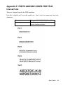
Appendix E: FONTS AND BAR CODES FOR PPLA ............................................ 85
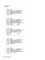
Internal Fonts........................................................................................................... 85
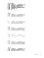
Courier Font Set ...................................................................................................... 90
Internal Bar Codes ................................................................................................... 94
Appendix F: FONTS AND BAR CODES FOR PPLB............................................. 99
Internal Fonts........................................................................................................... 99
Internal Bar Codes ................................................................................................. 103
Appendix F: STAND-ALONE OPERATION FOR KEYBOARD AND BARCODE
READER ........................................................................................... 105
Keyboard .............................................................................................................. 105
Barcode Reader..................................................................................................... 109
4
User's Guide
Table of Figures
Figure 1 - Fastmark 4000 Series Printer..............................................................................7
Figure 2 - Model and Serial Number Location.....................................................................8
Figure 3 - Shipped with Printer...........................................................................................9
Figure 4 - Front and Side View ........................................................................................10
Figure 5 - FM 4402 Back Panel.......................................................................................11
Figure 6 - FM 4602 and 4603 Back Panel.........................................................................11
Figure 7 - Power Cord Connection...................................................................................12
Figure 8 - Communication Cable ......................................................................................13
Figure 9 - Open Media Access Cover ..............................................................................15
Figure 10 - Printhead Latch and Side Access Cover..........................................................16
Figure 11 - Ribbon Take-Up Core....................................................................................16
Figure 12 - Ribbon Routing ..............................................................................................17
Figure 13 - Open Media Access Cover ............................................................................19
Figure 14 - Printhead Latch and Side Access Cover..........................................................20
Figure 15 - Outside Media Guide......................................................................................21
Figure 16 - Media Sensor Adjust Knob.............................................................................22
Figure 17 - Media Routing ...............................................................................................23
Figure 18 - Media Spindle Location ..................................................................................24
Figure 19 - Self Test FM4602/FM4603 PPLA ..................................................................27
Figure 20 - Self Test FM6402/FM4603 PPLB...................................................................28
Figure 21 - Self Test FM4402 PPLA................................................................................29
Figure 22 - Self Test FM4402 PPLB................................................................................30
Figure 23 - Fastmark 4000 Series Front Panel...................................................................33
Figure 24 - Entering into Set-up Mode ..............................................................................40
Figure 25 - Back Panel FM4602/FM4603 .........................................................................45
Figure 26 - Back Panel FM4402 ......................................................................................45
Figure 27 - Printhead (TPH) Maintenance........................................................................72
User's Guide
5
This page is blank
6
User's Guide
PRODUCT DESCRIPTION
This label printer is a high-performance, low-cost Direct Thermal/Thermal Transfer labeling
system. Its user-friendly design and affordable price set a new standard for the Desktop
Label Printer in retail, office and industrial applications.
The printer is designed with the most efficient memory management technology - True Speed
and prints at a speed of 1 to 6 inches per second. When bundled with its smart printer driver,
the user can easily print out bar codes, texts and graphics from any editing application (e.g.
CodeSoft, BarTender) under Windows 95/98/2000, and NT. All popular bar codes and fonts
are resident in the printer memory to handle versatile applications.
The solid designed mechanism allows quick and easy media (paper) and ribbon loading. The
optional Peel and Present with Internal Rewind and Cutter provide alternatives of fan-fold
label and continuous paper handling.
This printer is a compact, highly integrated, high performance and high resolution on-site
labeling system.
The User’s Manual will help you understand basic operations of the printer such as set-up,
installation, configuration and maintenance. Before reading the manual you should first
identify your printer model. The printer model name is located on the back of the printer on its
product label.
Figure 1 - Fastmark 4000 Series Printer
User's Guide
7
OVERVIEW
The Fastmark FM4000 series is currently comprised of 3 models:
•
FM4402
•
FM4602
•
FM4603
While these models are similar in many ways, important differences exist. Throughout this manual
instructions and illustrations applying to a particular model will be labeled accordingly otherwise the
instructions apply to all models.
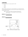
NOTE: The model number is printed on the compliance label attached to the
back of the printer. After un-packing please record the model number
below for reference.
MODEL No:
SERIAL No:
Model No: and
Serial No:
Figure 2 - Model and Serial Number Location
8
User's Guide
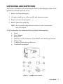
UNPACKING AND INSPECTION
This section is provided to assist you in taking the printer from the shipping container to the
application environment and ready for use.
1. Remove top foam packing piece.
2. Lift printer straight up out of box carefully with adequate assistance.
3. Remove accessory kit and supplies.
4. Remove printer from plastic bag.
NOTE: Save box and all packing materials for future use, in the event the printer
needs to be shipped.
Verify that the printer box contains the following materials when unpacking:
a.
b.
c.
d.
e.
f.
g.
Printer
User’s Manual
Power cord
Diskette(s) or CD for Windows 95/98/2000/NT and Label Design Software
Take up Core
A ribbon roll and a take-up ribbon core.
A media roll (not pictured)
Figure 3 - Shipped with Printer
User's Guide
9
INSTALLATION AND CONFIGURATION
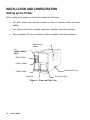
Setting up the Printer
Before setting up the printer you should first consider the following:
•
Flat stable surface with sufficient clearance to allow for interface cables and media
loading.
•
Free from excessive direct sunlight, temperature, humidity, dust, dirt, and debris.
•
Near a grounded AC power receptacle wired in compliance with local ordinances.
Media Viewing
Window
LCD
(FM4602 / FM4603
ONLY)
FEED / CONFIG.
PAUSE / CALIBR.
Media Access Cover
CANCEL / RESET
Media Exit
Front Access Door
Figure 4 - Front and Side View
10
User's Guide
Parallel Port
Serial Port
External Label
Feed Slot Cover
AC Voltage
Select Switch
Power Switch
Model No. and
Serial No.
AC Inlet
Receptacle
Figure 5 - FM 4402 Back Panel
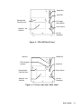
Switches
PS/2, Keyboard
Interface
Parallel Port
Serial Port
External Label
Feed Slot Cover
Power Switch
Model No. and
Serial No
AC Inlet
Receptacle
Figure 6 - FM 4602 and 4603 Back Panel
User's Guide
11
Connecting the Power Cord
1. Ensure printer Power Switch is off "0".
2. IMPORTANT: (FM4402 ONLY) Ensure the AC Voltage Select Switch is set to the
correct Voltage for this installation.
3. Remove the yellow voltage setting label from the AC Inlet Receptacle .
4. Connect the power cord to the AC Inlet Receptacle located on the back of the printer.
5. Connect AC power plug to a suitable AC source.
6. Connect either Centronics Parallel cable or RS-232 Cable.
CAUTION (FM4402 ONLY): Failure to properly set the AC
Voltage Select Switch will cause damage to the printer and will
Void the warranty. Ensure this is set properly before connecting
the AC power cord.
AC Voltage Select Switch
(FM4402 ONLY)
Power Switch
AC Inlet Receptacle
Figure 7 - Power Cord Connection
12
User's Guide
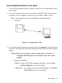
Connecting the Printer to Your Host
1. You can connect the printer with any standard Centronics cable to the parallel port of the
host computer.
2. Or, you can connect the printer with a serial cable to the RS-232C port of your computer
or terminal. (For PC compatibles, the RS-232C port is COM1, COM2 or COM3.)
Note: Using Centronics allows for a much higher communication speed
than serial.
Figure 8 - Communication Cable
3. If you use the serial port with your own cable, refer to the Appendix A and check the pin
connection. Be sure that the speed (baud rate) and protocol are the same between printer
and host.
Caution: Pin 9 on the serial port is directly connected to +5volts DC. It
is suggested that this pin be not connected in your cable, unless
required.
To change the Baud Rate:
FM4402: Send the <STX>KI8n command to the printer. See the System
Setting Commands section for more details.
FM4602/4603:
The switches on the back control Baud Rate. See the Back
Panel Switches section for more details
User's Guide
13
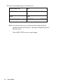
The factory default parameters of serial port are:
Speed (baud rate)
9600
Data format
1 start bit, 8 data bits and1 stop
bit.
Parity
None
Handshaking (Flow control) XON/XOFF as well as RTS/CTS
Note: It is not necessary to set a switch or send a command for the
parallel and serial port selection. The printer automatically detects
the active port.
Print a SELF-TEST to review serial settings.
14
User's Guide
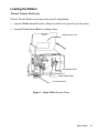
Loading the Ribbon
Thermal Transfer Media only
If Direct Thermal Media is used, skip to the section Loading Media.
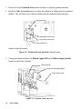
1. Open the Media Access Cover by lifting it up until it rests upon the top of the printer.
2. Open the Front Access Door by rotating it down.
Media Access Cover
Media Supply Guide
Media Supply Spindle
Front Access Door
Figure 9 - Open Media Access Cover
User's Guide
15
3. Rotate the Green Printhead latch counter-clockwise to open the printhead module.
4. Rotate the Side Access Door down to allow the ribbon to be loaded under the printhead
module. This will allow you to slide the ribbon under the printhead without having to
Printhead Latch
Upper Media Sensor Arm
Lower Media Sensor Arm
Side Access Door
thread it under the module.
Figure 10 - Printhead Latch and Side Access Cover
5. Unwrap the ribbon and place the Ribbon Supply Roll on the Ribbon Supply Spindle
located towards back of printer.
Take-up Spindle
Supply Roll and Supply Spindle
Empty Take-up core
Figure 11 - Ribbon Take-Up Core
16
User's Guide
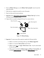
6. Place the Ribbon Take-up core on the Ribbon Take-Up Spindle located towards the
front of the printer.
7. Slide both cores completely towards the center of the printer.
8. Route the ribbon under the print mechanism.
9. Important: Route ribbon under and around back of Ribbon Take-Up Core before
attaching using tape or adhesive leader.
10. Tighten ribbon by manually rotating the Take-up Core counter-clockwise.
Ribbon Take-Up Roll
Ribbon Supply Roll
Ribbon Take-Up Spindle
Ribbon Supply Spindle
Front of Printer
Figure 12 - Ribbon Routing
11. Important: To ensure proper ribbon operation complete the following checklist:
q
Ribbon is wound ink in and feeding off the top of the Ribbon Supply Roll.
q
Ribbon is re-wound on Take Up Roll from the bottom.
q
Ribbon is routed above the Upper Media Sensor Arm. Only the media should
be below this arm.
q
When properly loaded both the Ribbon Supply and Ribbon Take-Up Rolls will
be rotating counterclockwise as shown on the Ribbon Routing picture.
User's Guide
17
12. Verify if the printer is set for Thermal Transfer Mode:
18
a.
To verify the FM4402 printer print a self-test. If the printer is not set for
Thermal Transfer mode, it can be set by using the Windows drivers, Utility
Software, or sending the appropriate printer commands via the host.
b.
To verify the FM4602 and FM4603 printers are set to Thermal Transfer
mode, switch 1 (on the back of the printer) is set to the off position.
User's Guide
Loading Media
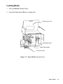
1. Fully open Media Access Cover.
2. Open the Front Access Door by rotating down.
Media Access Cover
Media Supply Guide
Media Supply Spindle
Front Access Door
Figure 13 - Open Media Access Cover
User's Guide
19
3. Rotate the green Printhead Latch counterclockwise to open the printhead.
4. Rotate the Side Access Door down to allow the media to be loaded under the printhead
module.
Printhead Latch
Upper Media Sensor Arm
Lower Media Sensor Arm
Side Access Door
Figure 14 - Printhead Latch and Side Access Cover
5. Slide the Media Supply Guide to the full widest position.
6. Ensure the media is face out with the labels feeding from the top of the roll. If not obtain
correctly wound media from your supplier
7. Place the media roll on the Media Supply Spindle.
8. Slide the roll fully towards the center of the printer.
9. Slide the Media Supply Guide towards the center of the printer until it is snug against
the media.
20
User's Guide
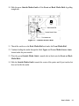
10. Slide the green Outside Media Guide off the Front and Back Media Rails by pulling
straight out.
Back Media Rail
Outside Media Guide
Front Media Rail
Figure 15 - Outside Media Guide
11. Thread the media over the Back Media Rail and under the Front Media Rail.
12. Continue feeding the media through the black Upper and Lower Media Sensor Arms
located under the print module.
13. Place the green Outside Media Guide (smooth side in) back onto the Front and Back
Media Rails.
14. Slide the Outside Media Guide towards the center of the printer until it just touches but
does not buckle the media.
User's Guide
21
15. Grasping the Sensor Adjust Knob and sliding in or out as needed can move the Media
Sensor. This is required only if the sensor must be moved to a specific location on the
label to detect a notch (hole) or gap.
Figure 16 - Media Sensor Adjust Knob
16. Important: To ensure proper media feeding and sensor operation, complete the following
checklist:
22
q
Media is wound Face Out (print side out) and feeding off the top of the roll.
q
Media is routed exactly as shown over the Back Media Rail and under the
Front Media Rail.
q
Media is routed between the Upper and Lower Media Sensor Arms located
under print module.
q
The green Outside Media Guide has been re-installed.
q
If required, the media sensor is adjusted directly over the notch (hole) or gap.
User's Guide
Upper Media Sensor Arm
Media
Back Media Rail
Front Media Rail
Lower Media Sensor Arm
Figure 17 - Media Routing
17. Rotate the Side Access Door up to close.
18. Rotate the green Print Head Latch clockwise fully to lock the printhead and Side
Access Door shut.
User's Guide
23
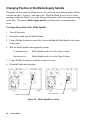
Changing Position of the Media Supply Spindle
The printer can store under the Media Access Cover an 8-inch outer diameter media roll that
is wound on either 1.5 inch or 3 inch inner cores. When the Media Access Cover is closed
touching on either the Media Cover or the bottom of the printer could cause unnecessary drag
on the form. The printer's Media Supply Spindle can be moved to accommodate these
issues.
To change the position of the Media Spindle:
1. Turn off the printer.
2. Remove the media from the Media Spindle.
3. Using a Phillips Screwdriver remove the 4 screws holding the Media Spindle to the center
of the printer.
4. Slide the Media Spindle to the appropriate position.
1.5 inch inner core:
Media Spindle needs to be in the Lower position.
3-inch inner core:
Media Spindle needs to be in the Upper Position.
5. Using a Phillips Screwdriver, install the 4 removed screws.
6. Reload the Media into the printer.
Upper Position
Lower Position
Figure 18 - Media Spindle Location
24
User's Guide
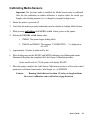
Calibrating Media Sensors
Important: The first time media is installed, the Media Sensors must be calibrated.
After the first calibration no further calibration is required unless the media type
(length, color, backing material, etc.) is changed or irregular feeding occurs.
1. Ensure the printer is powered off.
2. Verify that the media is properly loaded and routed as detailed in Loading Media Section.
3. While pressing and holding the PAUSE/CALIBR. button, power on the printer.
4. Release the PAUSE/CALIBR. button when:
a.
FM4402: The printer begins feeding labels.
b.
FM4602 and FM4603: The message “CALIBRATION …” is displayed on
the LCD.
5. Approximately 12 inches of media will be fed.
6. When feeding stops and the READY and MEDIA indicators stop blinking and remain
illuminated, the printer has completed the Label Sensor Calibration procedure.
On the models with a LCD, the printer will display 'READY'.
7. When the printer completes the Label Sensor Calibration procedure it will save the related
parameters (reflection characteristics, label length, etc.) to EEPROM.
Caution:
Running labels that are less than 1.5 inches in length without
the correct calibration can result in loss of gap detection.
User's Guide
25
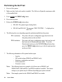
Performing the Self Test
1. Power off the printer.
2. Make sure that 4 inch wide media is installed. The Self-test will print the maximum width
of the installed label.
3. Press and hold the FEED/Config button.
4. Power on the printer.
5. Release the FEED/Config button when:
a.
FM 4402: The printer begins feeding labels.
b.
FM 4602 and FM 4603: The message “SELF TESTING…” is displayed on
the LCD.
6. The following the occur depending upon the emulation installed into the printer:
PPLA emulation:
The printer will print a configuration page then feed to the
first print position on the next label.
PPLB emulation:
The printer will print a configuration page, feeds one line and
then enter into its Hexadecimal print mode. To exit the
Hexadecimal mode press the CANCEL/Reset button then
press the FEED/Config button to go to the first print position
on the next label.
7. The following information will be printed on this report.
-
26
Font list
DIP switch settings (FM4602 and FM4603 only)
Hardware configuration and status
Label parameters
Firmware version
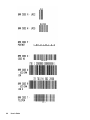
Note:
The following figures are examples of self-tests run on FM4402, and
FM4602/4603 with both PPLA and PPLB emulation's installed. The feature
setting on your printer may be different depending upon options selected.
Note:
Print samples printed on the FM4602 and FM4603 are similar.
User's Guide
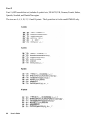
Self Test Pattern for FM4602/FM4603 PPLA
Figure 19 - Self Test FM4602/FM4603 PPLA
User's Guide
27
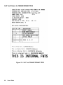
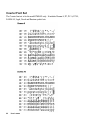
Self Test Pattern for FM4602/FM4603 PPLB
Figure 20 - Self Test FM6402/FM4603 PPLB
28
User's Guide
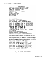
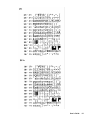
Self Test Pattern for FM4402 PPLA
Figure 21 - Self Test FM4402 PPLA
User's Guide
29
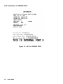
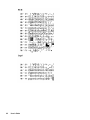
Self Test Pattern for FM4402 PPLB
Figure 22 - Self Test FM4402 PPLB
30
User's Guide
Resetting the Printer to Factory Default Settings
To reset the printer to its factory defaults after certain commands have been sent or settings
changed:
1. Power off the printer.
2. Press and hold the CANCEL/RESET button.
3. Power on the printer.
4. As the printer turns on the printer will:
FM 4402: All the LED's will come on with the Ribbon LED will begin flashing.
FM 4602/4603: The printer will display “E2PROM RESET …” on the LCD
and the READY LED will blink.
5. When the “READY” LED stops blinking and is continually on the printer's
initialization is completed. On the FM4602 and FM4603 models the Display will
indicated "READY" on the LCD.
6. The following parameters reset to Factory Defaults.
-
Label parameters
Heat (Darkness)
Speed
Symbol set (language)
Others for specific emulation
Notes:
1. All settings stored in non-volatile E2PROM are not erased when the printer looses
power.
2. Mechanical positions of the Switches on the back of FM 4602 and 4603 are not
changed with this procedure.
3. It is necessary to do a Label Sensor Calibration following a Reset.
4. The label count printed during the Self-Test can not be reset.
User's Guide
31
This is a blank page
32
User's Guide
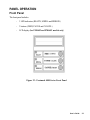
PANEL OPERATION
Front Panel
The front panel includes
-
3 LED indicators (READY, MEDIA and RIBBON)
-
3 buttons (FEED, PAUSE and CANCEL)
-
LCD display (for FM4602 and FM4603 models only)
Figure 23 - Fastmark 4000 Series Front Panel
User's Guide
33
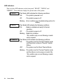
LED Indicators
There are three LED indicators on the front panel, “READY”, “MEDIA” and
“RIBBON”. These indicators display the present status of the printer.
X READY
The Ready LED indicates the following conditions:
ON
- The printer's powered is on.
Off
- The printer's power is off.
Blinking - Error condition (see Troubleshooting section for
details)
X MEDIA
X RIBBON
The Media LED indicates the following conditions:
ON
- Media is installed and ready for Normal
operation.
Off
- The printer's power is off.
Blinking - Media Out condition.
This condition only occurs following a media
motion request.
The Ribbon LED indicates the following conditions:
ON
- The printer is set for Thermal Transfer mode
and the printer contains a Thermal Transfer
Ribbon.
OFF
- The printer is set for Direct Thermal Mode.
Blinking - The printer is set for Thermal Transfer mode
and the ribbon is not moving or at end of life.
This condition only occurs following a media
motion request.
34
User's Guide
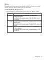
Buttons
Depending upon the printer model and current mode, the Front Panel buttons serve multiple
functions. Refer to the following tables for their specific functions.
Pressed and held down during Power UP
Upon completion of the desired function the printer will go into a READY condition.
Button
m FEED
Function
The printer performs an internal Self-Test and prints a
Configuration Report.
The FM4602/4603 models display "SELF TESTING" on the
LCD display.
m PAUSE The printer will do a Label Sensor Calibration test on the current
loaded media.
The FM4602/4603 models display "CALIBRATION" on the LCD
display.
m CANCEL The printer will reset the Non-Volatile memory (E2PROM) back
to factory defaults.
The FM4602/4603 models display "E2PROM RESET" on the
LCD display.
User's Guide
35
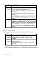
Pressed during normal operation
Button
m FEED
m PAUSE
Function
The printer will Feed a one label.
The printer will begin blinking the READY LED.
If printing the printer will STOP printing, and the READY
LED will blink.
If pressed a second time the printer will resume normal
operation.
The FM4602/4603 models will blink the READY LED and
display PAUSE on the LCD display while in the Paused
condition.
m CANCEL The printer will Stop printing and delete any further
information in the printer's buffer. The user must realign the
media by pressing the FEED button, following this function.
The FM4602/4603 models will blink the READY LED and
display CANCEL on the LCD display while in the Paused
condition.
Pressed for Special functions
The following functions are only available on the FM4602 and FM 4603 models.
Button
Function
m PAUSE Enter into the printer's Setup menu.
m CANCEL See the Front Panel Setup Menu section for more
information.
m PAUSE If held down for more than 5 seconds, the printer will allow
m CANCEL Language Selection.
See the Setting the Display Language section for more
information.
Note: Both buttons must be pressed at the same time for the above special functions.
36
User's Guide
LCD Display (FM4602 and 4603 models only)
For the model FM4602/FM4603 the front panel is equipped with a 2 row by 16 character
LCD display.
The basic function of the display is:
-
Display the printer status
-
Display the printer settings
-
Display's prompts requesting input data from a keyboard or barcode reader.
Standard Printer
After power on the following message is displayed on the LCD
READY (203,PPLA)
The first parameter is either 203 or 300. It stands for the printer's resolution.
FM4602 will display 203
FM4603 will display 300
The second parameter indicates the emulation (printer language), PPLA or PPLB.
With Keyboard Option installed
If a keyboard is plugged in, the following message is displayed on the LCD
READY (203,PPLA)
<ESC> FOR KEYBD
User's Guide
37
With Barcode Reader Option
If a barcode reader is connected and switches 6 through 8 are in the ON positions, the
displayed message will be.
READY (203,PPLA)
WITH B.C. READER
Abnormal Conditions
If any abnormal condition occurs the related message will be displayed. For example:
RIBBON OUT
38
User's Guide
Front Panel Set-up Menu
FM 4602 and FM 4603 models only
The Set-up menu is a list of printer features that affect the basic operation of the printer.
These are functions that can not normally be selected using software commands. Value
settings that are changed using the keypad are stored into E2PROM and are retained when
power is cycled. Value settings that are changed using software commands are temporary
changes and are not retained when power is cycled.
LCD and Button functionality in Set-up mode
Normal Mode
Buttons
Function
PAUSE +
CANCEL
Enters into set-up mode.
If in set-up mode, pressing these two keys will exit Set-up
mode and return to normal mode.
Setup Mode
Pressing this button will scroll to the next value of the
displayed feature.
Pressing this button will scroll to the next Feature.
FEED
PAUSE
CANCEL
Pressing this key will select the displayed value. It will also
save that value into non-volatile (E2PROM) memory.
LCD Displayed Information
Below is an example of a typical displayed Feature.
BAS E
0 0 0
S P EED
( I PS)
*
Feature name: BASE SPEED (IPS)
Feature Value: 000
Stored indicator:
*
User's Guide
39
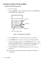
Procedure to Enter into Set-up Mode
FM 4602 and FM 4603 models only
1.
Power on the printer.
2.
When the “ READY” message is displayed on the LCD, press [PAUSE] and
the [CANCEL] buttons simultaneously.
Next Value
Next Feature
Enter Value
Press to Enter / Exit Setup Mode
Figure 24 - Entering into Set-up Mode
3.
Press [PAUSE] button to scroll to the feature that you want to change.
4.
Press [FEED] button to scroll to the desired value of the displayed feature.
5.
Once the desired value is displayed, press [CANCEL] button to save it. After
pressing the [CANCEL] button an * should appear in the last column. The * is
used to designate the stored value in non-volatile memory (E2PROM).
6.
Press both [PAUSE] + [CANCEL] buttons at the same time, to return to
normal mode.
Note: Do not enter set-up mode while the printer is printing or while the host is
sending data.
40
User's Guide
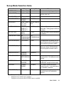
Set-up Mode Selection Items
Item
Range
Factory Default
Remarks
CUT/PEEL POS (mm)
+ 015 to + 015
0 mm
Controls cut and peeling position.
PRINT OFFSET (mm)
+ 015 to - 008
0 mm
Controls start vertical print position.
Positive value only.
TPH VER OFFS(mm)
+ 003 to - 003
0 mm
RECOVERY PRINT
ENABLE
DISABLE
MORE THAN 10,
5 to 7 mm,
8 to 9 mm.
NORMAL (~4”),
MORE (<3”),
MORE (<2”)
ENABLE
NORMAL (~4”)
2”, 3” and 4”(inches) stand for the
label width. Setting proper width can
avoid jam.
TYPE I,
TYPE II
TYPE I
Enable the type of cutter mechanism
is installed
1
GAP HEIGHT
2
CUTTER ROTATION
2
CUTTER TYPE
MORE THAN 10
mm
COMPRESSED FLASH NO
NO
COMPRESSION, COMPRESSION
COMPRESSED
WIN CON LEN (mm)
0 to 254 mm
0 mm
This takes effect only when you run
under Windows with bundled printer
driver and use continuous media.
BASE SPEED (IPS)
0 to 4 IPS
0 IPS
COUNTER ON LCD
ENABLED,
DISABLED
REFLECTIVE
SEE-THROUGH
ENABLED
REFLECTIVE
Select the proper type by the media
characteristics. Do calibration before
printing.
2
CHECKED,
IGNORED
CHECKED
For general media, set it to
“CHECKED” except for thick media.
BACKFEED
DISABLE,
ENABLE
DISABLE
This feature enables a manual
Present function. It can be disabled
by a software command.
3
010 to 040
012
This is the distance the printer will
move the form to a Presentation
position.
MEDIA SENS. TYPE
CUTTER SIGNAL
BACK DISTNCE(mm)
1
2
3
This is for the PPLB emulation only.
When you choose TLP2642/3642
driver the speed is limited under 2
ips.
Displayed only when Switch 4 is on.
Displayed only when Switch 3 enabled
Displayed only when the BACKFEED feature is enabled.
User's Guide
41
Notes:
1. To verify that a feature has been properly changed, cycle power on the printer.
2. Make sure the settings you desire has an * character by the value.
3. When changing the Media Sensor Type feature (Reflective and See-through); be
aware that the See-through sensor is 1 mm to the left of the Reflective sensor.
4. If graphics are stored with compression in the flashboard, do not use them under noncompression mode .
42
User's Guide
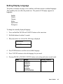
Setting Display Language
The printer can display messages, error condition, and feature menus in multiple languages.
This capability does not affect the printed text. The printer's LCD display supports six
languages:
English,
French,
German,
Italian,
Spanish and
Portuguese
To change the currently displayed language
1. Press and hold the PAUSE and CANCEL buttons at the same time.
2. Hold both buttons for about 5 seconds.
3. When the buttons are released the following is displayed
LANGUAGE
ENGLISH
*
4. Press FEED button to scroll the next available language.
5. Press CANCEL button to select the language for your need.
6. Pressing PAUSE or PAUSE+CANCEL buttons exits setting and enters normal mode.
Item
LANGUAGE
Range
ENGLISH,
FRENCH,
GERMAN,
ITALIAN,
SPANISH,
PORTUGUESE.
Factory Default
ENGLISH
User's Guide
43
Back Panel
The rear panel includes
-
An 8-bit DIP switch (FM4602/FM4603 models only)
-
A 36-pin Centronics connector
-
A 9-pin serial connector
-
A PS/2 keyboard connector (FM4602/FM4603 only)
-
A power switch and power connector
Caution: On the FM4402 model there is a voltage selection switch for selecting the
appropriate line voltage. Make sure to set the correct voltage (115V or
230V) before powering up the printer, otherwise the printer will be
damaged.
44
User's Guide
FM 4602/4603
Back Panel Switches
Parallel Port
PS/2, Keyboard Interface
Serial Port
External Label Feed
Slot Cover
Power Switch
AC Inlet Receptacle
Model Number and
Serial number
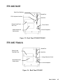
Figure 25 - Back Panel FM4602/FM4603
FM 4402 Models
Parallel Port
External Label
Feed Slot Cover
Serial Port
Voltage Selection Switch
Model Number and
Serial number
Power Switch
AC Inlet Receptacle
Figure 26 - Back Panel FM4402
User's Guide
45
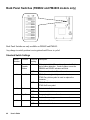
Back Panel Switches (FM4602 and FM4603 models only)
Back Panel Switches are only available on FM4602 and FM4603.
Any change in switch position is not registered until Power is cycled.
Standard Switch Settings
Switch
Number
Function
Position Description
setting
1
Thermal
Transfer
Ribbon
ON
Ribbon is installed. Thermal transfer mode. Enables
end-of-ribbon detection. If end-of-ribbon occurs the
RIBBON and READY indicators will blink.
OFF
Ribbon is not installed. Direct thermal.
ON
PPLA: Alternate (printable) control code set.
2
Euro Mark
PPLB: Euro dollar symbol is used to replace the
character ‘_’.
OFF
PPLA: Standard control set.
PPLB: No Euro symbol.
3
4
5
46
User's Guide
Cutter
Gap Size
ON
Cutter is installed.
OFF
Cutter is not installed.
ON
The gap length is more than 4 mm.
OFF
Media with normal gap or continuous media.
ON
Peeler is installed.
OFF
Peeler is not installed.
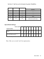
Switches 6, 7 and 8 are used to determine the printer's Baud Rate.
6
7
8
Baud rate
OFF
OFF
OFF
9600 (default)
ON
OFF
OFF
2400
OFF
ON
OFF
4800
ON
ON
OFF
19200
OFF
OFF
ON
38400
ON
ON
ON
Special Setting:
9600 and for barcode reader
Special Switch Settings:
Switch number
1
2
3
4
5
6
7
8
Special Condition
Sets Baud Rate to 9600 for a Bar Code
Reader
N/A
N/A
N/A
N/A
N/A
On
On
On
Clears Objects from the Flash that are
used with PPLB emulation. **
N/A
N/A
On
N/A
On
N/A
N/A
N/A
N/A - Switch position has not function in the condition.
Note: Make sure to set switch 3 and 5 their original positions.
User's Guide
47
PS/2 Keyboard I/F (FM4602 and FM4603 models only)
The special keyboard interface connector is available on the FM4602/FM4603 models.
This is for PS/2 keyboard or barcode reader with keyboard wedge. When this interface is
used, using the Centronics or RS-232 communication ports is discouraged. Use of the
PS/2 keyboard interface may only be operated in stand-alone mode.
The printer can automatically detect the keyboard. But if you use a barcode reader you
should set switches 6, 7 and 8 to the ON positions.
Before a keyboard or a barcode reader is connected make sure that the printer is set for
the following configuration.
-
Make sure that the printer has the PPLB emulation installed.
-
Make the desired form is download to the printer.
-
Make sure that a PS/2 keyboard or barcode reader with KB wedge is available.
(Refer to the Appendix for Stand-Alone Operation for further information.)
48
User's Guide
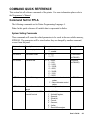
COMMAND QUICK REFERENCE
This section lists all software commands of the printer. For more information please refer to
the Programmer’s Manual.
Command Set for PPLA
The following commands are for Printer Programming Language A.
Note: In this quick reference all variable data is represented in Italics.
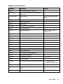
System Setting Commands
These commands will cause the related parameters to be saved in the non-volatile memory,
E2PROM. The parameters will be stored unless they are changed by another command,
or reset from the panel.
Command
Description
<STX>KI4n
Media empty check
<STX>KI7n
Set ribbon mode
<STX>KI8n
Set baud rate
<STX>KI;n
Control Code types
<STX>KXnnnn
Set continuous label
length
<STX>KI<m
Set symbol set for ASD
smooth font set
Parameter
n : ‘0’ - disable,
‘1’ - enable.
n : ‘0’ – DT,
‘1’ – TT.
Factory default
Enabled
TT with ribbon
(for FM4402)
n : ‘0’ – 9600,
9600 baud.
‘1’ – 600,
(for FM4402)
‘2’ – 2400,
‘3’ – 19200,
‘4’ – 4800,
‘5’ – 38400,
‘6’ – 1200,
‘7’ – 9600.
n : '0' - selects standard control For FM4402
codes.
'1' - Select alternate control
codes
nnnn : a 4-digit number, in mm
m : ‘0’ - USASCII,
‘1’ - United Kingdom,
‘2’ - Spanish,
‘3’ - Swedish,
‘4’ - French,
‘5’ - German,
‘6’ - Italian,
‘7’ - Danish/Norwegian.
0 for USASCII
User's Guide
49
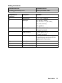
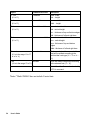
Interaction Commands
Such commands only apply to the serial port and allow the host to understand the status
and configuration of the printer.
Command
<SOH>#
<SOH>A
<SOH>B
<SOH>E
<SOH>F
Description
Response
Contents of the Response
from printer
Reset
Yes
<XOFF><XON>T
Send a readable status Yes
<8 bytes, Y/N> <CR>
string
byte 1 : Y - printer busy
byte 2 : Y - paper out
byte 3 : Y - ribbon out
byte 4 : N (always)
byte 5 : Y - printing
byte 6 : Y - printer paused
byte 7 : Y - label presented
byte 8 : N (always)
Toggle pause
No
condition
Send the number of
Yes
e. g.
labels to be printed
0000<CR>
no label left to be printed
Send status byte
Yes
n<CR>
Same as <SOH>A, except bits 1 to 8
corresponds to bytes 1 to 8 of <SOH>A.
Notes:
1.
Control codes for the printer commands.
Symbol
XON
XOFF
STX
SOH
ESC
LF
CR
Code (hexadecimal)
11H
13H
02H
01H
1BH
0AH
0DH
2. There is no space code in each command.
50
User's Guide
System Level Commands
Command
Description
<STX>a
Enable page/job echo characters
<STX>cxxxx
Set continuous paper length and disable
edge sensor
<STX>Dxxxxxxx
Memory dump**
<STX>Exxxx
Set copy count for stored label
<STX>e
Enable edge sensor
<STX>F
Feed a page
<STX>fxxx
Back feed from top position
<STX>G
Print stored label
<STX>I
Download graphics
Remarks
xxxxxxx : memory address in
HEX value
either PCX, BMP, PCX
or HEX format
<STX>J
Set pause for each label
<STX>j
Cancel pause
<STX>KQ
System configuration details
<STX>L
Enter label formatting state
<STX>Mxxxx
Set maximum label length
<STX>m
Set measurement in metric
<STX>n
Set measurement in inches
<STX>Oxxxx
Set start of print position
<STX>P
Enable data dump
<STX>Q
Clear memory (fonts & graphics)
<STX>r
Select reflective sensor
<STX>Sn
Set feed rate for motor
<STX>T
Print test pattern
<STX>Vn
Set Cutter or Peel and Present configuration n : ‘1’ - enable Cutter,
n : ‘A’, ‘B’ or ‘C’
‘4’ - enable Peel and Present
<STX>v
Printer version information
<STX>Wn
Graphics/fonts/labels and memory status
details
<STX>x
Release file from printer memory
n : ‘G’, ‘F’ or ‘L’. through RS232
User's Guide
51
Formatting Commands
Command
Description
:xxxx
Set cut amount
An
Set print mode
n : ‘1’- exclusive, ‘2’ - transparent
Cxxxx
Set horizontal offset
cxx
Set cut amount
Dwh
Set pixel width and height
E
Form feed and return to system level command mode
G
Store previous data to global register
<STX>Sn
Retrieve from global register. n : global register ID
Hxx
Set heating value, xx = 01 to 20
M
Toggle the mirror mode
m
Set measurement in metric
n
Set measurement in inches
Pn
Set print speed. n = ’A’, ‘B’, or ‘C’ **
Qxxxx
Set copy count
Rxxxx
Set vertical offset
r<n..n>
Retrieve label data from printer buffer. <n..n> : label name
sm<n..n>
Save label data to printer buffer. m : memory module,
<n..n> : label name
Txx
Set end-of-line code, xx : hex value
z
Change slash zero to normal zero (0).
+xx
Make auto increment for numeric or alphanumeric,
>xx
xx : count
-xx
Make auto decrement for numeric or alphanumeric,
<xx
xx : count
^xx
Set count amount, xx : count
Notes:
**
:
52
The formatting and editing commands should be grouped together, leaded by
<STX>L and ended by E command.
The parameter range is from ‘A’ to ‘K’ (1 to 6 ips) for the model
FM4602/FM4603, and for model FM4402 it is from ‘A’ to 'E' (1 to 4 ips).
User's Guide
Editing Commands
Command structure
Command function
Rthveeeyyyyxxxx<string><CR>
Printing text and bar codes
Components of
command
Description
Variables
R
print direction
‘1’,’2’,’3’ or ‘4’ (rotation)
t:
object type
‘0’ ~ ‘9’ and ‘:’ (fonts) **,
‘A’ ~ ‘Z’ and ‘a’ ~ ‘z’ (bar codes),
‘X’ (lines or boxes),
‘Y’ (graphics).
h
width multiplier
‘1’ to ‘9’ and ‘A’ to ’ O’.
‘0’ stands for default.
v
height multiplier
‘1’ to ‘9’ and ‘A’ to ’ O’,
‘0’ stands for default.
eee
bar code height
This is ignored for box, line and graphics.
It represents point size for font ‘9’ and
symbol set for Courier font**.
yyyy
Y coordinate
xxxx
X coordinate
<string>
depends on object types
User's Guide
53
Object
L : line
Command Structure
Lwwwhhh
(if t is ‘X’)
L : line
www : width,
hhh : height.
lwwwwhhhh
(if t is ‘X’)
B : box
Description
wwww : width,
hhhh : height.
Baaabbbcccddd
(if t is ‘X’)
aaa : horizontal width
bbb : vertical height
ccc : thickness of top and bottom edges
ddd : thickness of left and right bars
B : box
baaaavvvvccccdddd
(if t is ‘X’)
aaaa : horizontal width
vvvv : vertical height
cccc : thickness of top and bottom
edges
dddd : thickness of left and right bars
Bar code
bar code data
The bar codes (and human readable
text) will be printed according to the
selected bar code type (‘A’ ~ ‘Z’ or ‘a’ ~
‘z’).
text data
Such text data will be printed according
to the selected font (‘0’ ~ ‘9’).
file name
If t is ‘Y’ and the file was downloaded by
<STX>I command.
(if t is in the range ‘A’ to ‘Z’
or ‘a’ to ‘z’)
Text
(if t is in the range ‘0’ to ‘9’)
Note: **Model FM4603 does not include Courier fonts.
54
User's Guide
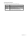
Font Downloading Commands
Such commands are only used for soft fonts with PCL format.
Command
Description
ESC*c###D
assign the soft fonts ID number (### : 100 ~ 999)
ESC)s###W
download font descriptor (### : length of font descriptor)
ESC*c###E
set character code (### : 1 ~ 255)
ESC(s###W
download character descriptor and image
(### : length of character descriptor and image)
User's Guide
55
This is a blank page.
56
User's Guide
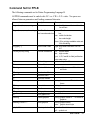
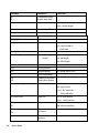
Command Set for PPLB
The following commands are for Printer Programming Language B.
All PPLB commands must be ended with <LF> or <CR>+<LF> codes. No spaces are
allowed between parameters and leading command character.
Command
Description
Parameter
font: 1 to 5 for internal font and A to Z
for soft font.
Ax,y,rot,font,hm,vm,nr,string
Print text.
Bx,y,rot,bar,nw,ww,v,hum,string
Print Bar Code.
nw: width of narrow
bar: barcode selection
bar
ww: width of wide bar
v:
bar code height
hum : B for printing readable code and
N for disabling.
bx,y,type,[…]
Print 2D Bar Code
type: M for Maxi code and P for PDF
417
Ccn,dn,just,step,string
Counter declaration
cn: counter index
dn: digit number
just: L,R,C and N for field justification
step: step value
Dp1
Heat setting
p1: density, 0 to 15
EI
Print soft font names
EKstring
Delete soft font
ESstring, ….
Download soft font
FE
End form store
FI
Print form names
FKstring
Delete form
string: form name or “*” to delete all
forms
FSstring
Execute form
string: form name
FSstring
Save form
string: form name
GGx,y,string
Print graphics
string: graphic name
GI
Print graphic list
GKstring
Delete graphics
string: graphic name or “*” to delete all
graphics
GMstring,size<LF>…
Store graphics
string: graphic name
size: graphic size in byte
Ip1,p2,001
Select symbol set**
p1: 7 or 8 data bits
p2: symbol set
string: soft font name or “*” to delete all
soft fonts
User's Guide
57
Command
Description
JB
Disable back feed**
JF
Enable back feed**
LEx,y,hlen,vlen
Line draw by exclusive
Parameter
hlen: horizontal length
vlen: vertical length
LOx,y,hlen,vlen
Line draw by OR
LWx,y,hlen,vlen
Draw white line
N
Clear frame buffer
O[,C][,N][,D]
Select options
Pp1[,p2]
Print label
p1: label set number
p2: copy number of
each label
PAp1[,p2]
Print automatic
Qp1,p2[,+p3]
Set label and gap
length**
p1: label length
p2: gap length
p3: offset length
qw
Set label width**
Rx,y
Set origin point**
Sp1
Set print speed
U
Print configuration
UN
Disable Error Report
US
Enable Error Report
Vvn,dn,just,string
Define variable
w: label width
p1: speed value, 4 to 6
vn: variable index
dn: digit number
just: L,R,C and N for
field justification
Xx,y,thick,ex,ey
Draw box
ZT
Set print direction
ex, ey: end position
thick: line thickness
ZB
ZS
ZN
?
58
ZB: print from bottom
Enable/disable storeto-Flash++
Download variables or
counters
User's Guide
ZS: print from top
power-on default is ZN(disabled)
Command
Description
Parameter
d1,hadj
Set horizontal position hadj: adjustment in dots.
adjustment**
d2,hadj
Set horizontal position same as d1, except it is no saved to
adjustment
E2PROM
Notes:
1.
x and y represent horizontal and vertical coordinate values.
2.
hm and vm stand for horizontal and vertical multipliers.
3.
rot is the rotation direction, its value is from 0 to 3.
4.
nr is either N for normal printing or R for reverse printing.
5.
string is bracket by double quote marks, e.g. “text”.
6.
**
7.
ZS takes effect only if flash memory board is installed.
Commands will cause the printer to save parameters to permanent storage
(E2PROM).
User's Guide
59
This is a blank page.
60
User's Guide
PRINTER DRIVER
The bundled printer driver is used for applications under Windows 95/98/2000 and Windows
NT. You may run any popular software application, such as MS-Word, as long as they are
for Windows and printing the contents to the printer through the designated driver.
Before starting installation you should:
♦ Check the contents of the driver to ensure it is complete.
♦ Make a backup copy of the driver.
♦ Read the README.TXT file for installation guide and change notices.
Under the root directory of the floppy or CD there are the following sub-directories
- WIN98
- WIN95
- NT40
- WIN2000
Select the proper directory for installation according to your operating system.
User's Guide
61
Driver Installation
♦
Windows needs to be running.
♦
Insert the appropriate printer driver diskette into the floppy disk drive.
1. Click the “Start” button.
2. Select “Settings”, then “Printers”
3. Double click the “Add Printer” icon.
4. At the Add Printer Wizard, Click “Next”.
5. Specify the “Network” or “Local” button and click the “Next” button.
6. Select “Installation from Floppy Disk” or "Have Disk".
7. Enter the floppy drive and path.
A:\WIN95
A:\NT40
A:\WIN98
A:\WIN2000
8. Select the printer name to be installed on the “List of Printers”, window. Click “Next”.
9. Select the communication port for the label printer. For parallel port, select “LPT1:”,
“LPT2:” or “LPT3”, for serial port select “COM1:” or “COM2:”., Click "Next".
10. You may wish to change the Printer Name to be more descriptive. Also select this
printer as the Default printer. Click "Next".
11. Select whether you want a test page to be printed, then click on Finish.
12. After the related files have been copied to your system, the procedure is complete.
Notes:
1. If you are just updating your driver, make sure to delete the previous version first.
2. If you install new bar code application software like BarTender, LabelView or
CodeSoft, the driver should be activated and set as the current printer driver.
62
User's Guide
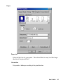
How to Use the Driver
After the driver is installed, you can open the Printer's dialogue box and make parameter
settings:
Windows 95/98/2000/NT4.0 - Start é Settings é Printers é Printer Name é Properties
Parameter setting:
After entering the Selected Printer you can change the parameters to meet your configuration
and needs. The following Format is from Windows 98.
User's Guide
63
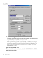
Details Tab
Print to the following port
This allows you to select the IO port to link with the printer. The port may be one
of parallel (LPT), serial (COM), network port or file.
If the communication port is the serial port (COM1: or COM2:), check the baud
rate and flow control as they must be consistent between host and printer. The
printer’s baud rate is printed on the following the self-test page. The factory
default baud rate is 9600.
Print using the following driver
This must match the printer that is attached (for the FM4402, FM4602 or FM4603)
when using the label printer.
64
User's Guide
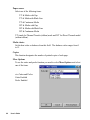
Paper
Paper size
Select the label size for your printer. The selected label size may be a little longer
than that of the physical label.
Orientation
Set portrait or landscape according to the print direction.
User's Guide
65
Paper source
Select one of the following items:
T/T & Media with Gap
T/T & Media with Black Line
T/T & Continuous Media
D/T & Media with Gap
D/T & Media with Black Line
D/T & Continuous Media
T/T stands for Thermal Transfer (ribbon) mode and D/T for Direct Thermal model
(without ribbon).
Media choice
Set the heat value or darkness from this field. The darkness value ranges from 0
to 15.
Copies
This function designates the number of printed copies of each page.
More Options
To use the cutter and peeler function you need to select More Options and select
one of the items.
w/o Cutter and Peeler
Cutter Enabled
Peeler Enabled
66
User's Guide
Device Options
Note: The maximum speed varies depending on model:
Fm 4402:
Max Speed is 4.0
FM 4602/4603: Max Speed is 6.0
User's Guide
67
This is a blank page.
68
User's Guide
TROUBLESHOOTING AND MAINTENANCE
Troubleshooting
Generally, when a malfunction or an abnormal condition occurs, the “READY” LED will
keep blinking. Printing and communication between the host and printer will stop.
To understand what the problem is you should first check the LED indicators and LCD
display on the front panel:
After the problems have been solved, press CANCEL to continue printing.
READY and MEDIA LED's blinking
LCD Displays MEDIA OUT
Possible Problems
Solutions
Remarks
Missing gap
- Check the media path
If using continuous media with Windows
then in the Paper Tab section
continuous should be selected.
- Check the position of the
media sensor.
- Check the paper sensor
Media out
- Check the Media Supply
Roll
Media not installed
- Install a Media roll
Media jam
- Clear the jam
Verify that the media is properly
positioned between the Media Sensor
Arms.
Verify that the media is routed correctly.
Printhead module is not - Close and latch the
closed
printhead module
Media Calibration lost
Run the Label Sensor Calibration procedure.
Ready and Ribbon LED Blinking
LCD displays RIBBON OUT
Possible Problems
Solutions
Remarks
Incorrect Switch setting
Switch 1 should be off
Direct Thermal media does not use a
ribbon.
Ribbon has run out
Supply the ribbon roll
Ribbon jam
Recover the jam
Ribbon sensor error
Replace the ribbon sensor
Note: The FM402DT does not use a ribbon and should not display this error.
User's Guide
69
Only the Ready LED blinks
FM4402 printer
Possible Problems
Solutions
Serial I/O error
Check the baud rate
Remarks
Check the flow control
Memory full
Add the extension RAM
Cutter failed, or jam
Check the cutter
at cutter
Clear the jam
Hardware error
Call for service
Only when cutter is installed.
Only the Ready LED blinks
FM4602 and FM4603 printer
LCD display
SERIAL IO ERROR
Possible Problems and Solutions Remarks
. Verify baud rate, format or
Not Applicable to the Parallel port.
protocol between host and
printer
. Check switches bits 6, 7 and 8.
CUTTER FAILED
. Check the media
. Check the connection between
cutter and main board.
For FM4602 and FM4603 verify switch
3 should be ON for cutter.
. Call for service.
MEMORY FULL
. Check the graphics and soft font Make sure to delete the graphics and
formats from host.
soft fonts, if the application software
no longer uses them
Host indicates “Printer Time Out”
•
•
70
Verify that the communication cable (parallel or serial) connection is secured to
both the port on the PC and to the connector on the printer.
Verify that the printer is power turned on (the power switch is at position ‘1’ and
the power LED is illuminated).
User's Guide
The data has been sent, but there is no output from the printer
•
•
Check the active printer driver, it should be Label Dr. for your Windows system
and the label printer.
Check the emulation and the print (command) file.
Vertical streaks in the printout usually indicate a dirty or faulty Printhead
Clean the printhead first, if they still persist, replace the printhead.
Unstable ribbon roll rotation
Check the label path and make sure the head latch is securely closed.
Poor printout quality
•
The ribbon may be not qualified.
•
The media may be not qualified.
•
Adjust the Darkness (heat temperature).
•
Slow down the print speed.
Recovery
In order to continue your print jobs after any abnormal conditions have been recovered, simply
press the CANCEL button or restart the printer. Make sure that the LED indicator is
illuminated and not blinking and remember to send your files to the printer again.
User's Guide
71
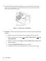
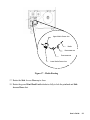
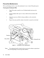
Preventive Maintenance
Before performing preventive or any other maintenance be sure to turn off the printer power.
Cleaning the Printhead (TPH)
1.
Turn off the printer, open the covers, Printhead module and remove the
ribbon.
2.
Rub the printhead with a piece of cotton, which has been moistened with
alcohol.
3.
Check for any traces of black coloring or adhesive on the cotton after
cleaning.
4.
Repeat if necessary until the cotton is clean after it is passed over the head.
Printhead
Platen Roller
Printhead Latch
Figure 27 - Printhead (TPH) Maintenance
Note:
72
The printhead should be cleaned at least every time the ribbon is replaced and
more often depending on actual usage and conditions.
User's Guide
Cleaning the Platen roller
Using cotton swab moistened with alcohol, clean the roller.
Note:
The roller should be cleaned whenever it has been in contact with foreign
materials such as dust or adhesives.
Cleaning the media compartment
Clean the media compartment with cotton, which has been moistened with mild detergent.
Every time a media roll is printed this compartment should be cleaned to reduce the
incidence dust.
User's Guide
73
This is a blank page.
74
User's Guide
Appendix A: Printer Specifications
General Specifications
Specification
Model FM4402
Resolution
203 DPI (8 dots/mm) 203 DPI (8 dots/mm)
Print method
Onboard RAM
Maximum label roll
diameter
Model FM4602
Model FM4603
300 DPI (12 dots/mm)
Direct thermal and thermal transfer
512K bytes
2M bytes
8 in. (203 mm) outside diameter
1.5 in. to 3.0 in. (38 mm to 76 mm) inside diameter
Label indexing
Black stripe and gap
Ribbon types
Wax, Wax/resin and Resin
Ribbon size
OD 3 in. (75mm)
ID 1 in. (25 mm)
I/O Interface
RS-232 serial and
Centronics parallel
ports with auto
polling
RS-232 serial and Centronics parallel ports
with auto polling for both ports.
PS/2 keyboard I/F for keyboard and barcode
reader
Dimension
9.8 in. x 16.0 in. x 10.2 in. (width x depth x height)
(250 mm x 410 mm x 260 mm)
Weight
26.8 lbs. (12 Kg)
24.6 lbs. (11 kg)
Electrical
CE, UL, CUL, FCC class A
110/220 VAC +10%, 50/60 Hz
Operating temperature
40° to 140°F (4° to 38°C)
Storage temperature
-40° to 140°F (-40° to 60°C)
Humidity
15 to 85% RH
Windows driver
Win95, 98, 2000 and NT
Printer emulation
PPLA or PPLB
Media type
Roll-feed, die-cut, continuous, fan-fold, tags, ticket in thermal paper or
plain paper.
Maximum print width
4.09 in (104 mm)
4.09 in (104 mm)
**
4.25 in (108 mm)
Maximum print length
45 in. (1143 mm)
33 in. (838 mm)
Maximum print speed
1 to 4 inches per
second.
(25.4 to101.6mm)
Front panel
3 buttons
3 LED indicators
Rear panel
Parallel and serial I/F 8-bit DIP switch, PS/2, parallel and serial I/F
1 to 6 inches per second
(25.4 to 152.4mm)
3 buttons
3 LED indicators
LCD display (16x2)
User's Guide
75
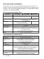
Fonts, Bar Codes and Graphics
The specifications for fonts, bar codes and graphics depend on the printer emulation. The
emulation is a printer programming language, through which the host can communicate with
your printer. There are two printer programming languages for all models FM4402, FM4602
and FM4603; they are PPLA and PPLB.
Printer Programming Language A, PPLA
Specification
General fonts
ASD smooth fonts
Symbol sets for smooth
fonts
Courier fonts
Soft fonts
Model FM4402
Model FM4602
6, 8, 10, 12, 14 and 18 points
Graphics
4, 6, 8, 10, 12, 14,
and 18 points
USASCII, UK, German, French, Italian, Spanish, Swedish, and
Danish/Norwegian
8 symbol sets (PC, PC-A, PC-B, EAMA-94, Roman ,
Legal, Greek and Russian)
Downloadable PCL fonts
Font expandability
Bar code types
Model FM4603
7 alpha-numeric fonts, OCR A and OCR B
1x1 to 24x24
Code 39, Code 93, Code 128/subset A,B,C, Codabar, Interleave 2 of 5,
UPC A/E/2 and 5 add-on, EAN-8/13, UCC/EAN-128, Postnet, Plessey,
HBIC, Telepen and FIM.
MaxiCode and PDF417 (2D symbologies).
PCX, BMP, IMG and HEX formats
Printer Programming Language B, PPLB
Specification
General fonts
Symbol sets (Code
pages)
Soft fonts
Font expandability
Bar code types
Graphics
Stand-alone operation
without host
76
User's Guide
Model FM4402, FM4602 and FM4603
5 fonts with different point sizes
8 bits: code page 437, 850, 852, 860, 863 and 865.
7 bits: USA, British, German, French, Danish,
Italian, Spanish, Swedish and Swiss.
Downloadable soft fonts
1x1 to 24x24
Code 39(checksum), Code 93, Code 128/subset A,B,C, Codabar,
Interleave 2 of 5(checksum), Matrix 25, UPC A/E 2 and 5 add-on, EAN8/13, Code 128UCC, UCC/EAN, Postnet, German Postcode.
MaxiCode and PDF417 (2D symbologies).
PCX and binary raster
FM4402 : KDU
FM4602/FM4603: Barcode reader or PC Keyboard
Optional Accessories
♦ Serial (RS-232) cable
♦ Peel and Present
♦ Cutter
♦ Flash memory (512 K bytes for FM4402 only)
♦ Font board
Notes:
The font board and flash modules use the same connector they
cannot be installed at the same time.
User's Guide
77
This is a blank page.
78
User's Guide
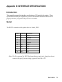
Appendix B: INTERFACE SPECIFICATIONS
Introduction
This appendix presents the interface specifications of I/O ports for the printer. These
specifications include pin assignments, protocols and detailed information about how to
properly interface your printer with your host or terminal.
Serial
The RS-232 connector on the printer side is a female, DB-9.
Pin
1
2
3
5
6
7
8
9
Direction
In
In
Out
Out
Out
In
Out
Definition
DSR
RxData
TxData
Ground
DTR
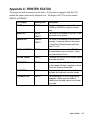
RTS
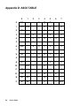
CTS
+5V
Note: Pin 9 is reserved for KDU (keyboard device unit) only, therefore do not
connect this pin if you are using a general host like a PC.
User's Guide
79
Connection with host:
Host 25S
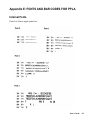
Printer 9P
Host 9S
Printer 9P
(PC or compatible)
(PC or compatible)
DTR 20
……….. 1 DSR
DTR 4
……….. 1 DSR
DSR 6
……….. 6 DTR
DSR 6
……….. 6 DTR
TX 2
……….. 2 RX
TX 3
……….. 2 RX
RX 3
……….. 3 TX
RX 2
……….. 3 TX
CTS 5
……….. 7 RTS
CTS 8
……….. 7 RTS
RTS 4
……….. 8 CTR
RTS 7
……….. 8 CTS
GND 7
……….. 5 GND
GND 5
……….. 5 GND
Alternatively you can just connect the 3 wires in the following way.
Host 25S
Printer 9P
Host 9S
Printer 9P
(PC or compatible)
(PC or compatible)
TX 2
……….. 2 RX
TX 3
………..
2 RX
RX 3
……….. 3 TX
RX 2
………..
3 TX
GND 7
……….. 5 GND
GND 5 ………..
pin 4
pin 4
pin 5
pin 6
pin 6
pin 7
pin 20
pin 8
5 GND
The simplest way to connect to other hosts (not PC compatible) or terminals is:
Printer
Terminal/Host
Pin 2- RxData
………… TxData
Pin 3- TxData
………… RxData
Pin 5- Ground
………… Ground
In general as long as the data quantity is not too large or you use Xon/Xoff as flow
control, there will be no flow control issues.
80
User's Guide
Serial port settings
Baud rate: 2400, 4800, 9600, 19200 and 38400.
To change the Baud Rate:
FM4402: Send the <STX>KI8n command to the printer. See the System
Setting Commands section for more details.
FM4602/4603: The switches on the back of the printer control Baud Rate.
See the Back Panel Switches section for more details
Data format: always 8 data bits, 1 start bit and 1 stop bit.
Parity: always no parity
Handshaking: XON/XOFF as well as CTS/RTS (hardware flow control).
Note: If you run an application with the bundled printer driver under Windows and use
the serial port, you should check the above parameters and set the flow control to
“Xon/Xoff” or “hardware”.
User's Guide
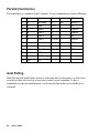
81
Parallel (Centronics)
The parallel port is a standard 36-pin Centronics. Its pin assignments are listed as following.
Pin
Direction
Definition
Pin
Direction
Definition
1
In
/STROBE
13
Out
SELECT
2
In
Data 1
14,15
3
In
Data 2
16
-
Ground
4
In
Data 3
17
-
Ground
5
In
Data 4
18
NC
6
In
Data 5
19 to 30 -
Ground
7
In
Data 6
31
NC
8
In
Data 7
32
9
In
Data 8
33 to 36 -
10
Out
/ACK
11
Out
BUSY
12
Out
PE
NC
Out
/Fault
NC
Auto Polling
Both the serial and parallel ports are active at the same time on this printer; i.e. data can be
received on either one, however no provision is made for port contention. If data is
transmitted to both ports simultaneously, it will cause the data in the received buffer to be
corrupted.
82
User's Guide
Appendix C: PRINTER STATUS
The printer has built-in monitors for the status. If the printer is equipped with the LCD
module the printer status can be displayed on it. The display on LCD is just for models
FM4602 and FM4603.
LCD display
Blinking LED
Description
PAUSE
READY
The printer is in a pause state. Press
PAUSE or CANCEL to return to normal
state.
MEDIA OUT
MEDIA
The media is uninstalled or used up. Load
new media to the printer.
READY
RIBBON OUT
RIBBON
READY
The ribbon is uninstalled or end-of-ribbon
occurred. Load new ribbon to the printer.
If using Direct Thermal media verify that
Switch 1 is off.
SERIAL IO ERROR
READY
The format or baud rate of the RS-232
communication may be incorrect. Verify
host and switches 6 to 8.
CUTTER FAILED
READY
The cutter can not cut off the media, check
the media and cutter.
MEMORY FULL
READY
The printer buffer is full. Possibly caused
by the loaded soft fonts, graphics or forms.
Check the format of these data.
HEAD OPEN
READY
The printhead latch is not closed. To print
the label the head latch must be closed.
P. SENSOR O.R.
READY
The media sensor is out of range during
calibration. Make sure the media is
installed and the label sensor is put under
the media.
User's Guide
83
Appendix D: ASCII TABLE
0
0
NUL
1
SOH
2
STX
3
1
XON
XOFF
4
5
NAK
3
4
5
6
7
0
@
P
`
p
!
1
A
Q
a
q
“
2
B
R
b
r
#
3
C
S
c
s
$
4
D
T
d
t
%
5
E
U
e
u
6
ACK
&
6
F
V
f
v
7
BEL
‘
7
G
W
g
w
8
BS
(
8
H
X
h
x
)
9
I
Y
i
y
*
:
J
Z
j
z
+
;
K
[
k
{
9
A
LF
B
84
2
ESC
C
FF
,
<
L
\
l
|
D
CR
-
=
M
]
m
}
E
SO
RS
.
>
N
^
n
~
F
SI
US
/
?
O
_
o
DEL
User's Guide
Appendix E: FONTS AND BAR CODES FOR PPLA
Internal Fonts
Fonts 0 to 8 have single symbol set.
User's Guide
85
86
User's Guide
User's Guide
87
Font 9
Font 9 (ASD smooth font set) includes 8 symbol sets, USASCII, UK, German, French, Italian,
Spanish, Swedish, and Danish/Norwegian.
The sizes are 4, 6, 8, 10, 12, 14 and 18 points. The 4-point font is for the model FM4603 only.
88
User's Guide
User's Guide
89
Courier Font Set
The Courier font set is for the model FM4602 only. It includes Roman-8, PC, PC-A, PC-B,
EAMA-94, Legal, Greek and Russian symbol sets.
90
User's Guide
User's Guide
91
92
User's Guide
User's Guide
93
Internal Bar Codes
This PPLA supports 20 one-dimensional bar codes and 2 two dimensional bar codes.
94
User's Guide
User's Guide
95
96
User's Guide
User's Guide
97
This is a blank page.
98
User's Guide
Appendix F: FONTS AND BAR CODES FOR PPLB
Internal Fonts
There are 5 internal fonts for the PPLB emulation.
Each has 6 eight-bit and 9 seven-bit symbol sets. Font 5 does not contain any lower-case
characters.
8 bit symbol sets
Code page 437, 850, 852, 860, 863 and 865
7 bit symbol sets
USA, British, German, French, Danish, Italian,
Spanish, Swedish and Swiss
User's Guide
99
100
User's Guide
User's Guide
101
102
User's Guide
Internal Bar Codes
The PPLB supports 26 one-dimensional bar codes and 2 two dimensional bar codes.
User's Guide
103
104
User's Guide
Appendix F: STAND-ALONE OPERATION FOR
KEYBOARD AND BARCODE READER
Apart from related hardware devices and PPLB emulation, in order to use keyboards and
barcode readers (scanner) you should follow the procedure as described below (FM4602 and
FM4603).
Note: The Fastmark family ships with PPLA emulation installed. To use the
external keyboard of to attach an external scanner, PPLB must be
installed. Contact your AMT Datasouth representative for instructions
on how to load this emulation.
Keyboard
1. Turn off the printer.
2. Make a form/program that will be used with the keyboard.
3. Connect the keyboard to the keyboard I/F.
4. Turn on the printer.
5. Download it to the printer and save the form to the flash memory.
6. Type the input data according to the instructions shown at the first row.
Pay attention to some major control functions
Key
Function
Esc
Enter or exit from keyboard mode
Backspace
Delete the last typed character.
F1
Next form if more than one forms exist.
Enter
- Select the form.
- End of typed data.
User's Guide
105
Example:
1. Make a command file for a form, KBD.FRM.
Command
Description
ZS
Enable the store to flash
FK"KBDFORM"
Delete the previous one
FS"KBDFORM"
Start of form
V00,15,N,"Product Name ?"
Variable and display message
C0,10,N,+1,"Product No. ?"
Counter and display message
Q50,24
Label dimension
q816
Label width
S2
Speed
D8
Darkness
ZT
Print from top
A550,20,0,4,1,1,R,"ABC COMPANY"
Fixed data
B550,60,0,2,2,4,40,B,C0
Barcode I25 for counter
A540,150,0,3,1,1,N,V00
Print the input product
FE
End of form
ZN
Disable the store to flash
2. Send the file, KBD.FRM to printer under MS-DOS
>COPY/B KBD.FRM LPT1:
3. Turn off the printer, connect the keyboard and then turn on the printer.
The message will be displayed on the LCD.
READY (203,PPLB)
<ESC> FOR KEYBD
106
User's Guide
4. Press <ESC> to enter the keyboard mode, the form name will be shown for the selection,
press <ENTER> key to select the form.
KBDFORM
↵
5. Key-in product name and number.
Product Name ?
Barcode Printer↵
↵
Product No. ?
0123456789↵
↵
6. Input the label count and copy count.
LABEL SET NO. ?
2↵
↵
COPIES PER LAB ?
3↵
↵
7. Press <ENTER> to continue for next label and repeat steps 5 to 7, or <ESC> to exit.
ENTER to go on,
Or ESC to return
User's Guide
107
Output
108
User's Guide
Barcode Reader
1. Turn off the printer.
2. Make a form for barcode reader; the form name must be “READER”.
3. Turn on the printer
4. Download it to the printer and save the form to the flash memory permanently.
5. Turn off the printer
6. Connect the barcode reader to the keyboard I/F.
7. Set bits 6, 7 and 8 of DIP switch to ON positions.
8. Turn on the printer.
9. Scan the barcode data according to the instructions shown at the first row.
Example:
1. Make a command file for a form, READER.FRM.
Command
Description
ZS
Enable the store to flash
FK"READER"
Delete the previous one
FS"READER"
Start of form
V00,15,N,"Product Name ?"
Variable and display message
C0,10,N,+1,"Product No. ?"
Counter and display message
Q50,24
Label dimension
q816
Label width
S2
Speed
D8
Darkness
ZT
Print from top
A550,20,0,4,1,1,R,"ABC COMPANY"
Fixed data
B550,60,0,2,2,4,40,B,C0
Barcode I25 for counter
A540,150,0,3,1,1,N,V00
Print the input product
PA1
Single copy
FE
End of form
ZN
Disable the store to flash
User's Guide
109
2. Send the file, READER.FRM to printer under MS-DOS
>COPY/B READER.FRM LPT1:
3. Turn off the printer.
4. Connect the barcode reader to the serial port.
5. Set switches 6, 7 and 8 on the back of the printer to the ON positions.
6. Turn on the printer.
7. The preprogrammed form, READER will start automatically executing.
Scan the product name and number from the printed bar codes by the barcode reader.
Product Name ?
APPLE↵
↵
Product No. ?
11223344↵
↵
8. A label will be printed. The copy count depends on the PA command for the READER
form. The printer will then return to the Ready for input display screen.
Output
110
User's Guide
Notes:
1. Set switches 6,7 and 8 to OFF positions and restart the printer to return to normal
printer functionality.
2. The bar code reader and keyboard cannot be connected to the PS/2 keyboard I/F
simultaneously.
3. When using a keyboard or a barcode reader, the communication with host is only
through the Centronics parallel port (Keyboard or Barcode reader port and the
serial port is the same. Only one can be used at a time.).
4. When using a Keyboard program the P command is not allowed.
5. When using the bar code reader/scanner form, a PA command must by included.
User's Guide
111
This is a blank page.
112
User's Guide
AMT Datasouth Corp.
Corporate Headquarters
4765 Calle Quetzal
Camarillo, CA 93012
(805) 388-5799 PH
(805) 484-5282 FX
Charlotte Operation
4216 Stuart Andrew Blvd.
Charlotte, NC 28217
(704) 523-8500 PH
(704) 525 6104 FX
www.amtdatasouth.com
AMT Datasouth International
Unit B, Pinnacle 15
Gowerton Rd, Brackmills
Northampton, NN4 7BW
England
+44 1604 763394 PH
+44 1604 760661 FX