1
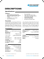
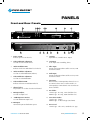
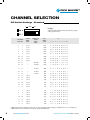
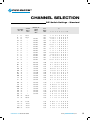
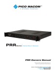
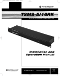
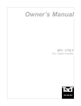
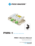
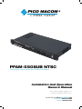
PICO MACOM
PFAM-550SUB NTSC
Frequency Agile Audio and Video Modulator
Installation And Operation
Owners Manual
Please read this manual thoroughly before use.
Keep this manual handy for future reference.
Visit Our Web-Site www.picomacom.com
Contact Us 858.546.5050
Toll Free 800.421.6511
PICO MACOM
Safeguard
Important Information
Product Inspection
CAUTION
Inspect the equipment for shipping damage.
Should any damage be discovered, immediately file a
claim with the carrier.
Important Safety Instructions
To insure proper installation and operation,
take a moment to read this guide before proceeding with
the installation. If you have any questions or comments
about the PFAM 550SUB agile modulator, please contact your dealer or have him contact the PICO MACOM
Service Center at the phone numbers at the bottom of
the page.
RISK OF ELECTRIC SHOCK
DO NOT OPEN
!
The lightning flash with arrowhead symbol, within an equilateral
triangle, is intended to alert the user to the presence of uninsulated
“dangerous voltage” within the product’s enclosure that may be of
sufficient magnitude to constitute a risk of electric shock to persons.
The exclamation point within an equilateral triangle is intended to
alert the user to the presence of important operating and maintenance (servicing) instructions in the literature accompanying the
appliance.
WARNING: TO REDUCE THE RISK OF FIRE OR ELECTRIC SHOCK, DO NOT EXPOSE
THIS APPLIANCE TO RAIN OR MOISTURE. DO NOT OPEN THE CABINET, REFER SERVICING TO QUALIFIED PERSONNEL ONLY.
CAUTION: TO PREVENT ELECTRIC SHOCK DO NOT USE THIS (POLARIZED) PLUG
WITH AN EXTENSION CORD RECEPTACLE OR OTHER OUTLET UNLESS
THE BLADES CAN BE FULLY INSERTED TO PREVENT BLADE EXPOSURE.
ATTENCION: POUR PREVENIR LES CHOCS ELECTRIQUES, NE PAS UTILISER CETTE FICHE POLARISEE AVEC UN PROLONGATEUR, UNE PRISE DE COURANT OU UNE AUTRE SORTIE DE COURANT, SAUF SI LES LAMES PEUVENT ETRE INSEREES A FOND SANS EN LAISSER AUCUNE PARTIE A DECOUVERT.
1. Read Instructions - All the safety and operating instructions
should be read before the appliance is operated.
2. 3. Retain Instructions - The safety and operating instructions
should be retained for future reference.
Heed Warnings - All warnings on the appliance should be
adhered to.
4. Follow Instructions - All operating and user instructions
should be followed.
5. Cleaning - Unplug this appliance from the wall outlet before
cleaning. Use a damp cloth for cleaning. Do not use liquid
cleaners or aerosol cleansers.
6. Do Not Use Attachments - not recommended by the
manufacturer or they may cause hazards.
www.picomacom.com
7. Water and Moisture - Do not use this product near water - for example, near a bathtub, washbowl, kitchen sink, laundry tub,
in a wet basement, or near a swimming pool - and the like.
8.
Accessories - Do not place this product on an unstable cart, stand, tripod, bracket, or table. The product may fall, causing serious injury to a child or adult, and serious damage to the
appliance.
9.
Ventilation - This video product should never be placed near or over a radiator or heat register. This video product should not be placed in a built-in installation such as a bookcase or rack unless proper ventilation is provided or the manufacturer’s in-
structions have been adhered to. Any slots or opening in the
cabinet are provided for ventilation. To ensure reliable operation of his video product and to protect it from overheating, these openings must not be blocked or covered. The openings should never be blocked by placing the product on a bed, sofa, rug, or other similar surface.
CONTACT US TOLL FREE 800-421-6511
PICO MACOM
EXAMPLE OF ANTENNA GROUNDING ACCORDING TO
NATIONAL ELECTRICAL CODE INSTRUCTIONS CONTAINED
IN ARTICLE 810 - "RADIO AND TELEVISION
EQUIPMENT"
Important Information
10.Grounding or Polarization - This video product is equipped
with either a three prong plug for 110 VAC use or a two prong
flat blade 220 volt type plug. Each type is to be inserted into
only the type of receptacle for which they are specifically
designed. Do not cut off the round grounding pin of a three
prong plug in order to be able to fit into a two prong receptacle
as this could cause injury and will void the warranty.
11. Power Sources - This product should be operated only from
the type of power source indicated on the marking label. If you
are not sure of the type of power supplied to your home, consult
your appliance dealer or local power company.
12.Power Cord Protection - Power supply cords should be rout-
ed so they are not likely to be walked on or pinched by items placed upon or against them. Pay particular attention to cords and plugs, convenience receptacles, and the point where they exit from the appliance.
13. Lightning - For added protection for this product during a
lightning storm, or when it is left unattended or unused for long periods of time, the unit should be disconnected from power source.
14. Power Lines - An outside antenna system should not be
located in the vicinity of overhead power lines, other electric light or power circuits, where it can fall into such power lines or circuits. When installing an outside antenna system, extreme care should be taken to keep from touching such power lines or circuits as contact with them may be fatal.
15. Overloading - Do not overload wall outlets and extension cords as this can result in risk of fire or electric shock.
16. Object and Liquid Entry - Never push objects of any kind into this product through openings as they may touch dangerous volt-
age points or short-out parts that could result in a fire or electric shock. Never spill liquid of any kind on the product.
17. Servicing - Do not attempt to service this product yourself as opening or removing covers may expose you to dangerous volt-
age or other hazards. Refer all servicing to qualified service
personnel.
18. Damage Requiring Service - Unplug this product from the wall outlet and refer servicing to qualified service personnel under
the following conditions:
a. When the power-supply cord or plug is damaged.
b. If liquid has been spilled, or objects have fallen into the
product.
c. If the product has been exposed to rain or water.
d.
If the product does not operate normally by following the
operating instruction. Adjust only those controls that are
covered by the operating instructions. An improper adjust-
ment may result in damage and will often require extensive work by a qualified technician to restore the product to its normal operation.
e. If the product has been dropped or the cabinet has been
damaged
CONTACT US 858.546.5050
INES
ER L
POW
GROUND CLAMP
SERVICE ENTRANCE
CONDUCTORS
STANDOFF
INSULATORS b
MAST
SERVICE
ENTRANCE
EQUIPMENT
ANTENNA
LEAD-IN WIRE
GROU
ND C
LAMP
S
POWER SERVICE GROUNDING
ELECTRODE SYSTEM
(e.g. interior metal water pipe)
ANTENNA
c
DISCHARGE UNIT
TO EXTERNAL ANTENNA
TERMINALS OF PRODUCT
BONDING JUMPER
d
GROUND WIRE
GROUND CLAMPS
OPTIONAL ANTENNA GROUNDING ELECTRODE
DRIVEN 8 FEET (2.44M) INTO THE EARTH
IF REQUIRED BY LOCAL CODES. SEE NEC
SECTION 810 - 21(f).
f. When the product exhibits a distinct change in performance
this indicates a need for service.
19.Replacement Parts - When replacement parts are required, be sure the service technician has used replacement parts speci
fied by the manufacturer or have the same characteristics as the
original parts. Unauthorized substitutes may result in fire, elec
tric shock or other hazards.
20. Safety Check - Upon completion of any service or repairs to this product, ask the service technician to perform safety checks to determine that the product is in proper operating conditions.
21. Outdoor Antenna Grounding - Before attempting to install this product, be sure the antenna or cable system is grounded so as to provide some protection against voltage surges and built-up static charges.
a.
Use No.10 AWG (5.3mm ) copper, No.8 AWG (8.4mm) aluminum, No.7 AWG (10mm) copper-clad steel or
bronze wire or larger, as ground wire.
b. Secure antenna lead-in and ground wires to house with standoff insulators spaced from 4 feet (1.22m) to 6 feet
(1.83m) apart.
c.
Mount antenna discharge unit as close as possible to where
lead-in enters house.
d. A driven rod may be used as the grounding electrode where other types of electrode systems do not exist. Refer to the National Electrical Code, ANSI/NFPA 70-1984 for
information.
e. Use jumper wire not smaller than No.6 AWG (13.3mm)
copper or equivalent, when a separate antenna grounding electrode is used.
NOTE TO THE CATV SYSTEM INSTALLER:
THIS REMINDER IS PROVIDED TO CALL THE CATV SYSTEM
INSTALLER’S ATTENTION TO ARTICLE 820 - 40 OF
THE NEC THAT PROVIDES GUIDELINES FOR PROPER
GROUNDING AND, IN PARTICULAR, SPECIFIES THAT THE
CABLE GROUND SHALL BE CONNECTED TO THE GROUNDING SYSTEM OF THE BUILDING, AS CLOSE TO THE POINT OF
CABLE ENTRY AS PRACTICAL.
www.picomacom.com
PICO MACOM
DESCRIPTIONs
Specifications
Features
•
•
•
•
Double heterodyne conversion provides
superior spurious harmonic output supression
Channels T7 through 78 capable (5.75 to
550MHz)
57 ±3 dB output, 5.75 to 550 MHz
SAW filtered and I.F. loop
•
•
•
•
•
•
Five year warranty*
Supports HRC, IRC frequency offsets
Factory aligned to FCC Docket 21006 for
frequency offsets and stability
Professional picture quality
Front panel -30 dB test point
Rear panel AC convenience outlet
Description
The PFAM-550SUB is a frequency agile double heterodyne conversion audio/video modulator. Its superior
sideband filtering provides adjacent channel compatibility and FCC Docket 21006 frequency accuracy. The
PFAM-550SUB provides 57 ±3 dB output from subband channel T7 through cable channel 78 including
HRC and IRC off-set frequencies. The channelization
can be changed by resetting the DIP switches accessed
through the front panel. High quality external modulation and RF level controls assure years of reliable
operation. The modulator is shipped with all internal
adjustments pre-set, and FCC Docket 21006 offsets are standard at no extra cost. Pico Macom Inc.
backs the product with a five year limited warranty. *
Specifications
RF
Audio
Channels: 89 channels (T7-T13, 2-78 & 95-99)
Output Level: 45 to 57 dBmV, adjustable from front panel
Output Impedance:
75 ohm
Output Return Loss: 15 dB
Audio/Video Ratio: Adjustable -7 to -22 dB
below visual carrier
Frequency Stability: ±5 KHz in aeronautical band.
Conforms to FCC Docket 21006
Spurious Output:
(In-band) CATV channels: -60dBc, A/V ratio @ 15dB
(In-band) Sub-band -57 dBc, A/V ratio @ 15dB
(Out-of Band) F≤550MHz
-54 dBc, A/V ratio @ 15dB
C/N (In Band): >58 dB
C/N (Out-of-Band):
>68 dB
Fv+6.5 MHz (Upper Adj. Reject): >60 dBc
Fv-1.5 MHz (Lower Adj. Reject): >60 dBc
I.F. Frequency: 45.75 MHz
Baseband Input Impedance: 600 ohms unbalanced
Baseband Input Level: 0.5 Vp-p for 25 kHz deviation
Pre-Emphasis: 75 microseconds
Flatness: 1.5 dB max. 50 Hz to 15 KHz
General
Power Input: 117 VAC, 60 Hz or 220 VAC, 60 Hz
-10° C to +50°
Operating Temperature: Dimensions: 19” L x 12” D x 1.75” H
Weight: 8.2 pounds
All “F” type
Connectors: Video
Input Level: 0.6 V p-p min for 87.5% modulation
Input Type: Composite video negative sync
Frequency Response: ±0.8 dB 30 Hz to 4 MHz
Differential Gain: <3% (10 to 90% APL)
Differential Phase:
<2° (10 to 90% APL)
Chrominance Luminance Delay:
<50 nsec
Hum and Noise: -60 dB @ 87.5 modulation
Video Signal to Noise: -60 dB minimum (weighted)
Input Level Range: 0.5 V to 1.5 V P-P
* One year warranty if sold outside U.S.A.
www.picomacom.com
(Specifications subject to change without notice)
CONTACT US TOLL FREE 800-421-6511
PICO MACOM
Panels
Front and Rear Panels
Front and Rear Panels
1
PFAM 550SUB
2
3 4
5 6
7
8
9
550MHz Sub-Band Extended Agile A/V/ Modulator
VIDEO
AUDIO
RATIO
POWER
AUDIO
OVER
MOD
AUDIO
MOD
VIDEO
VIDEO OVER
MOD MOD
TEST POINT
CHANNEL
RF LEVEL
R
RF OUT
-30 dB
IF IN
IF OUT
VIDEO
IN
250 VAC
0.5A
AUDIO
IN
SUB
600VA MAX
117VAC
60 Hz 20 W
17
18
CATV
FUSE
10
11
12
13
14
15
16
1. Power on LED:
Indicates power is on when lit.
11. I.F. Input:
Input from I.F. scrambler or I.F. output.
2. Video/Audio Ratio adjustment:
Used to set level of audio carrier.
12. I.F. Output:
To I.F. input or to scrambling device.
3. Audio Modulation LED:
Indicates aural over modulation level when lit.
13. Video Input:
Accepts video output from satellite receiver, VCR and CCTV camera.
4. Audio Modulation adjustment:
Used to set audio modulation (Volume).
5. Video Modulation adjustment:
Used to set video modulation.
6. Video modulation LED:
Indicates video over-modulation when lit.
7. Channel Select:
Dip switches are used to select desired channel.
8. RF Output Adjust:
Used to set output level.
9. -30dB Output test monitor:
Used to monitor RF output level.
10. RF Output:
Connect this port to distribution system.
CONTACT US 858.546.5050
14. Audio Input:
Accepts audio output from satellite receiver, VCR and CCTV camera.
15.
SUB CATV:
When switch is in SUB position, channels 7 to 13 are converted to T7 to T13. When switch is in CATV position, CATV channels 2 to 78 and 95 to 99 are available.
16. Fuse holder:
117VAC type - 0.5 amp, 125V slow-blow fuse.
220VAC type - 0.5 amp, 250V slow-blow fuse.
17. Convenience Outlet:
117VAC type - shown
220VAC type - 2 flat blade type (not shown)
18. Power Cord:
117VAC type - Three wire, standard U.S.A. type.
www.picomacom.com
PICO MACOM
InstaLlation
Installation Procedures
Adherence to these precautions will help prevent problems during
initial installation of the PFAM 550SUB.
1. Connect the I.F. jumper from the I.F. output to the I.F. input on the rear panel.
2. Connect the PFAM 550SUB to a 115 VAC ground-
ed receptacle. Observe the lit LED light indicating power is on.
3. Using a signal level meter or spectrum analyzer,
set the output level.
4. Check the aural carrier level. It should be set at
15 dBmV below the video carrier.
.
WARNING: When connecting the PFAM 550SUB directly to a TV set, attenuate the output sufficiently to
prevent overdriving the TV. The front panel test point is
useful for monitoring modulator output.
5. Connect a 1.0 volt peak-to-peak video source to the “VIDEO IN” on rear panel. Connect the “RF OUT” to a TV set, and compare the contrast and brightness to a known signal (use off-air signal to ensure a proper modulation level). If necessary, adjust the video
modulation until proper contrast is observed.
6. Connect an audio source to the “AUDIO IN” on rear of the unit. Set audio modulation (peak deviation) to
25 kHz with the audio modulation adjustment. A known
off-air signal and a TV may be used to set adjustment for
equal audio level.
7. Connect the “RF OUTPUT” to a proper combining
network.
FREQUENCY OFFSETS
T
he Federal Communications Commission requires
that cable system modulators which operate in the
aircraft communications and navigation bands be offset in frequency by 12.5 kHz. The PFAM 550SUB PLL
FREQUENCY oscillator is factory set to comply with FCC requirements
for frequency accuracy (+/- 5 kHz) in the aeronautical
communication and navigation bands.
CHANNEL NUMBER OFFSET
108 to 118 MHz ......................................... A,B,C ...................14,15,16 ...............12.5 kHz
118 to 137 MHz ........................................ A-1, A-1 ...............99,98 ....................25 kHz
225 to 328.6 MHz ..................................... K - DD .................24-40 ....................12.5 kHz
328.6 to 225.4 MHz ................................... FF .........................42 .........................25 kHz
335.4 to 400 MHz ...................................... GG- QQ................43-53 ....................12.5 kHz
Harmonically Related Coherent (HRC) video carriers and Incrementally Related Coherent (IRC) video carriers are
CATV channel assignment methods to reduce the effect of intermodulation products. The technique is used in expensive phase-locked headends where all units are tied to a master 6.0003 MHz oscillator with a maximum error of
1 Hz.
www.picomacom.com
CONTACT US TOLL FREE 800-421-6511
PICO MACOM
InstalLation
PFAM 550SUB 2-Way Application
LHCP
RHCP
AUDIO IN
RF OUT
DSS RECEIVER
PFAM550mt
RF OUT
RF IN
VIDEO IN
AUDIO IN
DSS RECEIVER
PFAM550mt
RF OUT
RF IN
VIDEO IN
AUDIO IN
DSS RECEIVER
PFAM550mt
RF OUT
RF IN
VIDEO IN
AUDIO IN
DSS RECEIVER
RF OUT
RF IN
VIDEO IN
AUDIO IN
PFAM550mt
DSS RECEIVER
PFAM550mt
RF OUT
RF IN
VIDEO IN
AUDIO IN
DSS RECEIVER
PFAM550mt
RF OUT
RF IN
VIDEO IN
AUDIO IN
DSS RECEIVER
PFAM550mt
RF OUT
RF IN
VIDEO IN
AUDIO IN
DSS RECEIVER
PFAM550mt
RF OUT
RF IN
VIDEO IN
AUDIO IN
DSS RECEIVER
PFAM550mt
RF OUT
RF IN
VIDEO IN
AUDIO IN
DSS RECEIVER
PFAM550mt
RF OUT
RF IN
VIDEO IN
AUDIO IN
DSS RECEIVER
VIDEO IN
AUDIO IN
PFAM550mt
RF OUT
VIDEO IN
PFAM550mt
RF OUT
RF IN
DSS RECEIVER
RF IN
TSB-21G
2-WAY 1 GHz
SPLITTER
CA-30/870AR
DISTRIBUTION
AMPLIFIER
TO DISTRIBUTION
SYSTEM
TM
PFAM550mt
RF IN
VIDEO IN
AUDIO IN
OUT
-3.5dB
DSS RECEIVER
SPEC
RF OUT
INPUT
PFAM550mt
RF IN
VIDEO IN
AUDIO IN
5-1000MHz
DSS RECEIVER
-130dB EMI
RF OUT
TSB-21G
PFAM550mt
RF IN
VIDEO IN
AUDIO IN
TRU
DSS RECEIVER
OUT
-3.5dB
RF IN
PHC-24G
TSMS-2150X-16A
RF OUT
PFAM550SUB CH.T8
VIDEO IN
SECURITY
CAMERA
VIDEO OUT
RF OUT
PFAP550MS
SUB-BAND RETURN PATH
CONTACT US 858.546.5050
www.picomacom.com
PICO MACOM
CHANNEL SELECTION
DIP Switch Settings - Standard
1
ON -0
OFF -1
CHANNEL
STD. EIA
thru
10
Example:
Adjacent DIP switch drawing illustrates the proper
setting for channel 2.
ON
1 2 3 4 5 6 7 8 910
VIDEO
FREQ.
MHz
OFFSET CH.
VIDEO
FREQ.
MHz
OSC.
FREQ.
MHz
S1
1 2 3 4 5 6 7 8 9 10
2
2
5 5.25
1014
0 1 0 0 0 0 0 0 0
0
3
3
6 1.25
1020
1 1 0 0 0 0 0 0 0
0
4
4
6 7.25
1026
0 0 1 0 0 0 0 0 0
0
5
5
7 7.25
1036
1 0 1 0 0 0 0 0 0
0
6
6
8 3.25
1042
0 1 1 0 0 0 0 0 0
0
A-5
95
9 1.25
1050
1 1 1 1 1 0 1 0 0
0
A-4
96
9 7.25
1056
0 0 0 0 0 1 1 0 0
0
A-3
97
1 03.25
1062
1 0 0 0 0 1 1 0 0
0
A-2
98
*
109.2750
1068
0 1 0 0 0 1 1 0 1
0
A-1
99
*
115.2750
1074
1 1 0 0 0 1 1 0 1
0
A
14
*
121.2625
1080
0 1 1 1 0 0 0 0 0
1
B
15
*
127.2625
1086
1 1 1 1 0 0 0 0 0
1
C
16
*
133.2625
1092
0 0 0 0 1 0 0 0 0
1
D
17
1 39.25
1098
1 0 0 0 1 0 0 0 0
0
E
18
1 45.25
1104
0 1 0 0 1 0 0 0 0
0
F
19
1 51.25
1110
1 1 0 0 1 0 0 0 0
0
G
20
1 57.25
1116
0 0 1 0 1 0 0 0 0
0
H
21
1 63.25
1122
1 0 1 0 1 0 0 0 0
0
I
22
1 69.25
1128
0 1 1 0 1 0 0 0 0
0
7
7
1 75.25
1134
1 1 1 0 0 0 0 0 0
0
8
8
1 81.25
1140
0 0 0 1 0 0 0 0 0
0
9
9
1 87.25
1146
1 0 0 1 0 0 0 0 0
0
10
10
1 93.25
1152
0 1 0 1 0 0 0 0 0
0
11
11
1 99.25
1158
1 1 0 1 0 0 0 0 0
0
12
12
2 05.25
1164
0 0 1 1 0 0 0 0 0
0
13
13
2 11.25
1170
1 0 1 1 0 0 0 0 0
0
Sub-Band Selection: Channel T7 thru T13 use the same DIP switch settings as standard 7 thru 13. To change to
Sub-Band move slide switch on back panel to Sub-Band position.
www.picomacom.com
CONTACT US TOLL FREE 800-421-6511
PICO MACOM
CHANNEL SELECTION
DIP Switch Settings - Standard
CHANNEL
STD. EIA
VIDEO
FREQ.
MHz
OFFSET CH.
VIDEO
FREQ.
MHz
S1
OSC.
FREQ.
MHz
1 2 3 4 5 6 7 8 9 10
1
0
1
0
1
0
1
0
1
0
1
0
1
0
1
0
0
1
1
0
0
1
1
0
0
1
1
0
1
0
0
0
0
1
1
1
1
0
0
0
0
1
0
1
1
1
1
1
1
1
1
0
0
0
0
0
1
1
1
1
1
1
1
1
1
0
0
0
0
0
0
0
0
0
0
0
0
0
0
1
1
1
1
1
0
0
0
0
0
0
0
0
0
0
0
0
0
0
0
0
0
0
0
0
0
0
0
0
0
0
0
0
0
0
0
0
0
0
0
0
0
0
0
0
0
0
0
0
1
1
1
1
1
1
1
1
1
1
1
1
J
K
L
M
N
O
P
Q
R
S
T
U
V
W
23
24
25
26
27
28
29
30
31
32
33
34
35
36
2 17.25
2 23.25
*
*
*
*
*
*
*
*
*
*
*
*
229.2625
235.2625
241.2625
247.2625
253.2625
259.2625
265.2625
271.2625
277.2625
283.2625
289.2625
295.2625
1176
1182
1188
1194
1200
1206
1212
1218
1224
1230
1236
1242
1248
1254
AA
BB
CC
DD
EE
FF
GG
HH
II
JJ
37
38
39
40
41
42
43
44
45
46
*
*
*
*
*
*
*
*
*
*
301.2625
307.2625
313.2625
319.2625
325.2625
331.2750
337.2625
343.2625
349.2625
355.2625
1260
1266
1272
1278
1284
1290
1296
1302
1308
1314
1
0
1
0
1
0
1
0
1
0
0
1
1
0
0
1
1
0
0
1
1
1
1
0
0
0
0
1
1
1
0
0
0
1
1
1
1
1
1
1
0
0
0
0
0
0
0
0
0
0
1
1
1
1
1
1
1
1
1
1
0
0
0
0
0
0
0
0
0
0
0
0
0
0
0
0
0
0
0
0
0
0
0
0
0
1
0
0
0
0
1
1
1
1
1
0
1
1
1
1
KK
LL
MM
NN
OO
PP
QQ
RR
SS
47
48
49
50
51
52
53
54
55
*
*
*
*
*
*
*
4 03.25
4 09.25
361.2625
367.2625
373.2625
379.2625
385.2625
391.2625
397.2625
1320
1326
1332
1338
1344
1350
1356
1362
1368
1
0
1
0
1
0
1
0
1
1
0
0
1
1
0
0
1
1
1
0
0
0
0
1
1
1
1
1
0
0
0
0
0
0
0
0
0
1
1
1
1
1
1
1
1
1
1
1
1
1
1
1
1
1
0
0
0
0
0
0
0
0
0
0
0
0
0
0
0
0
0
0
0
0
0
0
0
0
0
0
0
1
1
1
1
1
1
1
0
0
TT
56
4 15.25
1374
0
0 0
1 1
1 0
0
0
0
UU
57
4 21.25
1380
1
0 0
1 1
1 0 0
0
0
VV
58
4 27.25
1386
0
1 0
1 1
1 0 0
0
0
WW
59
4 33.25
1392
1
1 0
1 1
1 0 0
0
0
CONTACT US 858.546.5050
www.picomacom.com
PICO MACOM
CHANNEL SELECTION
DIP Switch Settings - Standard
CHANNEL
STD. EIA
VIDEO
FREQ.
MHz
OFFSET CH.
VIDEO
FREQ.
MHz
OSC.
FREQ.
MHz
S1
1 2 3 4 5 6 7 8 9 10
XX
60
439.25
1 3 98
0
0
1
1
1
1
0
0
0
0
YY
61
445.25
1 4 04
1
0
1
1
1
1
0
0
0
0
ZZ
62
451.25
1 4 10
0
1
1
1
1
1
0
0
0
0
AAA
63
457.25
1 4 16
1
1
1
1
1
1
0
0
0
0
BBB
64
463.25
1 4 22
0
0
0
0
0
0
1
0
0
0
CCC
65
469.25
1 4 28
1
0
0
0
0
0
1
0
0
0
DDD
66
475.25
1 4 34
0
1
0
0
0
0
1
0
0
0
EEE
67
481.25
1 4 40
1
1
0
0
0
0
1
0
0
0
FFF
68
487.25
1 4 46
0
0
1
0
0
0
1
0
0
0
GGG
69
493.25
1 4 52
1
0
1
0
0
0
1
0
0
0
HHH
70
499.25
1 4 58
0
1
1
0
0
0
1
0
0
0
III
71
505.25
14 64
1
1
1
0
0
0
1
0
0
0
JJJ
72
511.25
1 4 70
0
0
0
1
0
0
1
0
0
0
KKK
73
517.25
14 76
1
0
0
1
0
0
1
0
0
0
LLL
74
523.25
14 82
0
1
0
1
0
0
1
0
0
0
MMM 7 5
529.25
14 88
1
1
0
1
0
0
1
0
0
0
NNN
76
535.25
14 94
0
0
1
1
0
0
1
0
0
0
OOO
77
541.25
15 00
1
0
1
1
0
0
1
0
0
0
PPP
78
547.25
1 5 06
0
1
1
1
0
0
1
0
0
0
* THESE CHANNELS SHALL BE OFFSET IN ACCORDANCE WITH FCC RULING SECTION 76.612
10
www.picomacom.com
CONTACT US TOLL FREE 800-421-6511
PICO MACOM
Warranty
WARRANTY
Five Year Limited Warranty*
Limited Warranty
Pico Macom warrants to the original purchaser that all of its new products are of sound design, quality materials and
workmanship at the time of manufacture and will be free from related defects for one year from the original purchase
date. Pico Macom will repair or, at its discretion, replace without cost to the original purchaser, the product which,
upon inspection by Pico Macom, appears to be defective or not conforming to factory specifications. Pico Macom
will cover the cost of parts, labor, and return freight from factory.
Five-Year Limited Warranty
Most products designated as “Headend Electronics” are further covered by an extended 4-year period beyond the
expiration of the original 1-year warranty, for a full 5-year period. Qualified equipment requiring factory repair during the extended 4-year period is covered under our re-certification program. Recertification fees under this program
shall not to exceed 20% of the product’s List Price and whenever possible, Pico Macom will attempt to upgrade
performance to the latest improved specification.
Warranty Limitations
This warranty excludes coverage of damage or inoperability resulting from (1) use or installation other than in strict
accordance with Pico Macom’s written instructions, (2) disassembly or repair by someone other than Pico Macom
or a Pico Macom authorized repair center, (3) misuse, misapplication or abuse, (4) alteration, (5) lack of reasonable care or (6) wind, ice, snow, rain, lightning, power surges, or any other weather conditions or acts of God. Pico
Macom’s warranty with respect to third-party proprietary sub-assembly modules and/or private-label products are
limited to the duration and terms of third-party vendors’ warranty. Pico Macom shall in no event and under no circumstances be liable or responsible for any consequential, indirect, incidental, punitive, direct or special damages
based upon breach of warranty, breach of contract, negligence, strict tort liability or otherwise or any other legal
theory, arising directly or indirectly from the sale, use, installation or failure of any product acquired by buyer from
Pico Macom. This limited warranty extends to the original purchaser.
Pico Macom reserves the right to modify or discontinue this warranty at Pico Macom’s sole discretion without notification. No other warrantees are expressed or implied.
* One year warranty if sold outside U.S.A.
CONTACT US 858.546.5050
www.picomacom.com
11
PICO MACOM
6260 Sequence Drive
San Diego
California 92121
Phone: 858.546.5050
Sales: 858.546.5055
Fax: 858.546.5051
www.picomacom.com
[email protected]
Printed in the U.S.A.