1
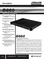
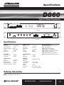
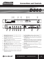
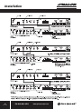
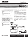
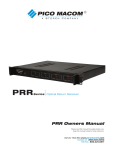
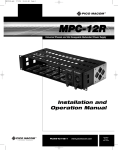
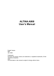
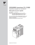
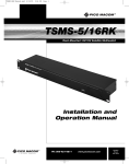
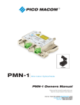
PROFESSIONAL SERIES
D860
Agile A/V Stereo Demodulator
Installation and
Operation Manual
Ph: 800-421-6511
www.picomacom.com
Operation
Manual
Rev. 12/05
Description
PROFESSIONAL SERIES
D860
Agile A/V Stereo Demodulator
132 Channel Input Range
5.75-806MHz(CATVT7-T13AND2-125)
and TV 2-69
Broadcast quality specifications for
unparalleled picture quality
Keyed AGC system provides
excellent picture
stability
Quadrature
single-tuned audio
detection guarantees
superior audio quality
Digital display provides quick channel
identification
Bright LED bar graph provides quick
reference of modulation levels
Envelopedetectionensuresexceptional differential gain
and phase
45.75 MHz composite IF output
allows tuner monitoring, encoder,
ghost canceling and video
override applications
SAWfilteredforpreciseadjacentchannel rejection
Back-panel switch enables
sub-bandoperationforreceivingremote
TV origination, making it even more
flexible for institutional cable systems
IRC and HRC input and output offset
available for frequency
setting in systems using
offset channels
2
Rev. 12/05
Ph: 800-421-6511
D860
Agile A/V Stereo Demodulator
The MACOM D860 is a frequency agile professional re-broadcast grade, microprocessor
controlled CATV demodulator. Its phase-locked loop frequency control, envelope signal detection and superior SAW filtering minimize adjacent channel interference and
assure accurate and spurious-free performance. The unit accepts any NTSC television
signal in the 5.75-806 MHz frequency range, converting it to baseband video and audio
while maintaining over 60 dB S/N ratio. The sub-band capabilities allow the reception
of remote channel origination for redistribution over the entire cable system, making it
the ideal signal processor in government and institutional environments. A rear panel
switch enables sub-band channel operation. IRC and HRC offsets can be activated via
push-button switches on the front panel. The unit’s PLL circuitry in conjunction with the
nonvolatile memory contained in the microprocessor ensures easy and reliable channel
selection and restoration. The D860 provides three additional outputs: (a) an IF output to
monitor tuner status and use in encoder, ghost canceling and video override applications, (b) a 4.5 MHz sub-carrier output, and (c) a broadband multiplex (MPX) output
for high quality BTSC stereo pass-through. The D860 demodulator is shipped with all
internal adjustments preset. The MACOM line is backed by an industry leading 5-year
limited warranty.
www.picomacom.com
Specifications
PROFESSIONAL SERIES
D860
Agile A/V Stereo Demodulator
Front View
Rear View
Specifications
RF INPUT
Frequency Range: 5.75-806 MHz
CATV Channels: T7-125
Broadcast Channels: 2-69
Level: 0-15 dBmV
Impedance: 75 ohms
Return Loss: -18 dB
AUDIO OUTPUT
Level: Impedance: MPX Output
Level: Format: Impedance: IF OUTPUT
Composite Level:
Impedance: 35 dBmV
75 Ohm
4.5 MHZ OUTPUT
Level: Impedance: VIDEO OUTPUT
Level: Impedance: Differential Gain: Differential Phase: Chrom /Lumin Delay: .8-1.0 V p-p
75 Ohm
<2% typ
<1° typ
±30 ns
GENERAL
Power Input: Operating
Temperature: Dimensions: 1.75˝(H)
Weight: Connectors: Audio: RELATED PRODUCTS
EAS-12B Emergency Override System
A860 Agile Modulator
A860S Agile Stereo Modulator
F860-Channel Fixed Modulator
F860S-Channel Fixed Stereo Modulator
C860 Bi-Directional Combiner
L860 Bi-Directional Launch Amplifier
DSP806 HDTV Agile Channel Processor
.8-1.0 V p-p
600 Ohm
.8-1.0 V p-p
BTSC
600 Ohm
35dBmV
75 Ohm
90-260 VAC, 12 W
-10°C to 50°C
19˝(L) x 12˝(D) x
7.8 lbs.
RF & Video “F” type
“F” type & Terminal strip
Ordering Information
D860
Agile A/V Stereo Demodulator
Ph: 800-421-6511
www.picomacom.com
3
Rev. 12/05
Safeguards
PROFESSIONAL SERIES
D860
Product Inspection
Inspect the equipment for shipping damage. Should any damage be discovered, immediately file a claim with the carrier.
Important Safety Instructions
To ensure proper installation and operation, take a moment to read this guide before proceeding with the installation. If you have any questions
or comments about the D860 Agile A/V Stereo Demodulator, please contact your dealer or have him contact the PICO MACOM Service Center
at the phone number on the bottom of the page.
The lightning flash with arrowhead symbol, within an
equilateral triangle, is intended to alert the user to the
presence of uninsulated “dangerous voltage” within the
product’s enclosure that may be of sufficient magnitude
to constitute a risk of electric shock to persons.
The exclamation point within an equilateral triangle is
intended to alert the user to the presence of important
operating and maintenance (servicing) instructions in
the literature accompanying the appliance.
WARNING: TOREDUCETHERISKOFFIREORELECTRICSHOCK,DONOTEXPOSETHISAPPLIANCETORAINORMOISTURE. DONOT OPEN THE CABINET.
REFER SERVICING TO QUALIFIED PERSONNEL ONLY. TO PREVENT ELECTRIC SHOCK DO NOT USE THE(POLARIZED)PLUGWITHANEXTENSIONCORD
RECEPTACLE OR OTHER OUTLET UNLESS THE BLADES CAN BE FULLY INSERTED TO PREVENT BLADE EXPOSURE.
1.Read Instructions: All safety and operating instructions should be
read before the appliance is operated.
2.Retain Instructions: The safety and operating instructions should
be retained for future reference.
3. Heed Warnings: All warnings on the appliance should be
adhered to.
4.Follow Instructions: All operating and user instructions should be
followed.
5.
Cleaning: Unplug this appliance from wall outlet. Use a damp cloth
for cleaning. Do not use liquid cleaners or aerosol cleansers.
s6.Do Not Use Attachments not recommended by the manufacturer;
they may cause hazards.
7.Accessories: Do not place this product on an unstable cart, stand,
tripod, bracket, or table. The product may fall, causing serious
injury to persons and serious damage to the appliance.
8.Damage Requiring Service: Disconnect this product from the system and refer servicing to qualified service personnel under the
following conditions:
a. If liquid has been spilled, or objects have fallen into the product.
b. If the product has been exposed to rain or water.
c. If the product does not operate normally by following the
operating instruction. Adjust only those controls that are
covered by the operating instructions. An improper adjustment
may result in damage and will often require extensive work
by a qualified technician to restore the product to its normal
operation.
d. If the product has been dropped or the cabinet has been damaged.
e. When the product exhibits a distinct change in performance —
this indicates a need for service.
9.Replacement Parts: When replacement parts are required, be sure
the service technician has used replacement parts specified by
the manufacturer or have the same characteristics as the original
parts.
4
Rev. 12/05
Ph: 800-421-6511
10.Safety Check: Upon completion of any service or repairs to this
product, ask the service technician to perform safety checks to
determine that the product is in proper operating conditions.
NOTE TO THE CATV SYSTEM INSTALLER
THIS REMINDER IS PROVIDED TO CALL THE CATV SYSTEM INSTALLER’S
ATTENTION TO ARTICLE 820-22 OF THE NEC THAT PROVIDES GUIDELINES
FOR PROPER GROUNDING AND, IN PARTICULAR, SPECIFIES THAT THE
CABLE GROUND SHALL BE CONNECTED TO THE GROUNDING SYSTEM OF
THE BUILDING, AS CLOSE TO THE POINT OF CABLE ENTRY AS PRACTICAL.
www.picomacom.com
PROFESSIONAL SERIES
Connections and Controls
D860
1.Video Modulation Level: Indicates video modulation level. Green
LED signifies correct video level.
11.I.F. Out (45.75 MHz): A sample I.F. output is used to monitor the
status of the tuner and for use with other up converters.
2. Audio Modulation Level: Indicates audio modulation level. Green
LED signifies correct audio level.
12. 4.5 MHz Output: Provides audio output for stereo applications
using a BTSC stereo encoder when the source has been previously BTSC encoded.
3. TV/CATV: Use this button to select TV (chs. 2-69), CATV (chs.
2-125) or HRC and IRC offset channels.
4. Channel Select Buttons: Use these buttons to select channel of
interest.
5. Channel Number Display: Indicates demodulated channel.
6.Mode LEDs: Indicate which mode is operative: TV, Standard
CATV, CATV/IRC or CATV/HRC.
13. MPX Out: This output provides a .8-1 V p-p non de-emphasized
audio signal. This is an alternate connection for stereo. Before
connecting this Output to the audio input of a modulator, the preemphasis filter on the modulator must be disabled.
14.Audio Out: Connect this port to the audio input of a modulator or
TV monitor.
7.Input Test Point: Connect TV to this port to monitor input signal.
15. Audio Terminal Strip: Alternate audio connection to connect to
bare wire audio leads.
8. RF IN: This port accepts a 0 to 15 dBmV signal from an antenna
or cable line.
16.RS485: Space provided for future RS485 utilization.
9.
T Band/Cable In: This switch selects T Band or Cable Input signals.
17.IEC Power Cord Connection: Connect power cord here. Will accept
90 to 260 VAC.
10.Video Out: This output provides a standard 1 volt peak to peak
baseband video signal. Connect this output to the video input or
a modulator or TV monitor.
Ph: 800-421-6511
www.picomacom.com
5
Rev. 12/05
Installation
6
Rev. 12/05
Ph: 800-421-6511
PROFESSIONAL SERIES
www.picomacom.com
Installation
PROFESSIONAL SERIES
D860
Installation
Signal Combining Methods
It is recommended that assistance be available to safely install equipment
in equipment racks.
PICO MACOM recommends connecting the headend components in
the following manner: Each of the modulators, signal processors or
strip amplifiers output are connected to a combining network. Either
a C860, PHC-12G or a PHC-24G headend combiner may be used to
accomplish this purpose.
1.Install chassis in equipment rack (equipment rack sold separately)
by supporting the bottom and rear of D860 at the desired elevation in rack.
2.Line up the side holes of chassis with the tapped equipment rack
holes.
3.Insert the provided screws through the side holes in chassis and
thread into the tapped equipment rack holes.
4.Fasten the bottom screws first, then fasten top screws (tighten
securely).
5.Connect a cable from the output of the RF source (antenna or
CATV feed) to the RF IN connector of the D860.
6.Connect a cable from the VIDEO OUT of the D860 to the video
input of the modulator (not provided).
7.Connect a cable from the AUDIO OUT of the D860 to the audio
input of the modulator (not provided).
8.If the modulator provides a 4.5MHz composite audio input,
connect a cable from the 4.5MHz output of the D860 to the
4.5MHz composite input of the modulator.
9.Connect a cable from the output RF connector of the modulator
to the input connector of combining system.
10.Connect D860 power cord to receptacle supplying uninterrupted
line power (LED on front panel will illuminate).
The C860, PHC-12G or PHC-24G passive headend combiners consist
of two rows of directional couplers combined by a hybrid splitter.
Normally, the odd channels are combined on one row while even
channels are combined on the other row of directional couplers for
maximum isolation. The output of the combiners may be connected
to the input of a launch amplifier such as a CA-30RK550 or
CA-30RK1000. The output of the amplifier is connected to the main
distribution line.
The CHC-16U/550 and CHC-16U/860 sixteen channel active combiners provide both signal combining and post amplification of the
headend signals. The combiner gain is 15 dB per channel.
A 24 channel system hook-up is shown below. (The same combining result may be accomplished by using a single PHC-24G). The
outputs are combined via a two-way splitter, which is connected to
an attenuator pad (if necessary) and a launch amplifier, such as an
L860 or CA-30RK1000. The input levels to the combiner, whether from
a modulator, signal processor or a strip amplifier, must be at the same
amplitude.
11.Depress the TV/CATV button until the LED
illuminates next to the desired format.
12.For CATV sub-band receive operation,
slide the switch on the rear panel of the
D860.
13.Select the receive channel by repeatedly
depressing the channel up or down button
until the desired channel number is displayed.
Ph: 800-421-6511
www.picomacom.com
7
Rev. 12/05
Warranty
PROFESSIONAL SERIES
D860
Five-Year Limited Warranty*
Pico Macom, Inc. warrants to the original purchaser this product shall be free of defects in material and craftsmanship with only the
limitations or exclusions set out below.
During the warranty period, Pico Macom, Inc. or an authorized Pico Macom service facility will provide, free of charge, the parts and
labor necessary to correct defects in material and workmanship.
Warranty Duration
This warranty shall terminate five years* from the original date of purchase of the product or at a time the product is:
1. Misused or damaged due to neglect or improper installation
2.Modified
3. Repaired by someone other than the warrantor
4. Sold by the original purchaser
Statement of Remedy
To obtain such a warranty service, contact the salesperson where the product was obtained. You will be issued a Return Authorization
(RA) number which will be used to track your product. Be prepared to provide:
1. The model number and channel number of the product
2. The date of purchase
3. A specific identification of the problem
Deliver the products to Pico Macom, Inc. or ship the products in the original packing material to the address below. Include satisfactory
evidence of the date of purchase.
Products will not be accepted by Pico Macom, Inc. without the RA number clearly indicated on the shipping label.
The foregoing constitutes the Pico Macom, Inc. entire obligation with respect to this product and the original purchaser and any user
or owner shall have no other remedy and no claim for incidental or consequential damages. Some states do not allow limitations on
how long an implied warranty lasts or do not allow the exclusions or limitation of incidental or consequential damages, so the above
limitation and exclusion may or may not apply to you.
This warranty gives you specific legal rights, and you also have rights, which vary from state to state. (U.S.A.)
Pico Macom, Inc.
6260 Sequence Drive
San Diego, California 92121
8
Rev. 12/05
Ph: 800-421-6511
www.picomacom.com