1
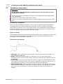
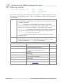
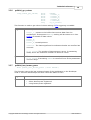
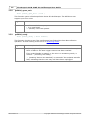
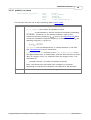
PicoScope 2104 & 2105
PC Oscilloscopes
User guide
PS2100044-1.0
Copyright 2006 Pico Technology Limited. All rights reserved.
I
PicoScope 2104 & 2105 PC Oscilloscope User Guide
Table of Contents
1 Introduction
.............................................................................................1
1 Overview ...................................................................................................1
...................................................................................................1
2 Safety symbols
...................................................................................................2
3 Safety warning
4 FCC notice...................................................................................................2
5 CE notice ...................................................................................................3
...................................................................................................3
6 Licence conditions
...................................................................................................4
7 Trademarks
8 Warranty ...................................................................................................4
9 Company ...................................................................................................4
details
.............................................................................................5
2 Product information
1 Minimum ...................................................................................................5
system requirements
...................................................................................................6
2 Installation
instructions
...................................................................................................7
3 Specifications
.............................................................................................8
3 Technical reference
1 Driver
...................................................................................................8
...................................................................................................8
2 Driver error
codes
...................................................................................................9
3 Functions
...................................................................................................20
4 Advanced
features
...................................................................................................24
5 Using different
modes
...................................................................................................25
6 Programming
.............................................................................................27
4 Troubleshooting
1 Software...................................................................................................27
error codes
5 Glossary
Index
PS2100044-1.0
.............................................................................................28
......................................................................................................30
Copyright 2006 Pico Technology Limited. All rights reserved.
Introduction
1
Introduction
1.1
Overview
1
The PicoScope 2104 and 2105 PC Oscilloscopes are low-cost handheld instruments
that are fully USB 2.0-capable and backwards-compatible with USB 1.1. There is no
need for an additional power supply, as power is taken from the USB port.
With the PicoScope software, you can use your instrument as a PC Oscilloscope and
spectrum analyser; and with the PicoLog software, you can use it as a data logger.
Each product pack contains the following items:
PicoScope 2104 or 2105 PC Oscilloscope
Software CD
Accessories kit
Quick start guide
Please read the important information in this introductory section and then proceed to
the Installation instructions.
1.2
Safety symbols
Warning Triangle
This symbol indicates that a safety hazard exists on the indicated
connections if correct precautions are not taken. Ensure that you read
all safety documentation associated with the product before using it.
Copyright 2006 Pico Technology Limited. All rights reserved.
PS2100044-1.0
2
1.3
PicoScope 2104 & 2105 PC Oscilloscope User Guide
Safety warning
We strongly recommend that you read the general safety information below before
using your PicoScope PC Oscilloscope for the first time. Safety protection built in to
the equipment may cease to function if the equipment is used incorrectly. This could
cause damage to your computer, or lead to injury to yourself and others.
Maximum input range
The PicoScope 2104 and 2105 PC oscilloscopes are designed to measure voltages in
the range -20 V to +20 V and are protected against continuous or transient
overvoltages of up to ±50 V. Any voltages in excess of ±50 V may cause permanent
damage to the oscilloscope or to your computer.
Measurement category
PicoScope 2000 Series PC Oscilloscopes are rated for use in measurement category I
(EN61010 CAT I), which covers measurements on circuits not connected to the
mains. You must not use your PicoScope PC Oscilloscope to make measurements on
any circuit directly connected to the mains, unless you use a purpose-built isolating
probe rated for the appropriate voltage and measurement category.
Safety grounding
The PicoScope PC Oscilloscopes connect directly to the ground of a computer through
the interconnecting cable provided.
As with most oscilloscopes, avoid connecting the ground input to any source other
than ground. If in doubt, use a meter to check that there is no significant AC or DC
voltage between the ground input of the oscilloscope and the point to which you
intend to connect it. Failure to check may cause damage to your computer, or lead to
injury to yourself and others.
You should assume that the product does not have a protective safety earth.
Repairs
PicoScope PC Oscilloscopes contain no user-serviceable parts. Repair or calibration of
the unit requires specialised test equipment and must be performed only by Pico
Technology. Spare probe tips are available from Pico Technology and its authorised
distributors.
1.4
FCC notice
This equipment has been tested and found to comply with the limits for a Class A
digital device, pursuant to Part 15 of the FCC Rules. These limits are designed to
provide reasonable protection against harmful interference when the equipment is
operated in a commercial environment. This equipment generates, uses, and can
radiate radio frequency energy and, if not installed and used in accordance with the
instruction manual, may cause harmful interference to radio communications.
Operation of this equipment in a residential area is likely to cause harmful interference
in which case the user will be required to correct the interference at his own expense.
For safety and maintenance information see the safety warning.
PS2100044-1.0
Copyright 2006 Pico Technology Limited. All rights reserved.
Introduction
1.5
3
CE notice
The PicoScope 2104 and 2105 PC Oscilloscopes meet the intent of the EMC directive
89/336/EEC and have been designed to EN61326-1 (1997) Class A Emissions
and Immunity standard.
The devices also meet the intent of the Low Voltage Directive and have been
designed to meet the BS EN 61010-1:2001 IEC 61010-1:2001 (safety
requirements for electrical equipment, control, and laboratory use) standard.
1.6
Licence conditions
The material contained in this release is licensed, not sold. Pico Technology Limited
grants a licence to the person who installs this software, subject to the conditions
listed below.
Access
The licensee agrees to allow access to this software only to persons who have been
informed of these conditions and agree to abide by them.
Usage
The software in this release is for use only with Pico products or with data collected
using Pico products.
Copyright
Pico Technology Limited claims the copyright of, and retains the rights to, all material
(software, documents etc.) contained in this release. You may copy and distribute the
entire release in its original state, but must not copy individual items within the
release other than for backup purposes.
Liability
Pico Technology and its agents shall not be liable for any loss, damage or injury,
howsoever caused, related to the use of Pico Technology equipment or software,
unless excluded by statute.
Fitness for purpose
Because no two applications are the same, Pico Technology cannot guarantee that its
equipment or software is suitable for a given application. It is your responsibility,
therefore, to ensure that the product is suitable for your application.
Mission-critical applications
This software is intended for use on a computer that may be running other software
products. For this reason, one of the conditions of the licence is that it excludes usage
in mission-critical applications; for example, life-support systems.
Copyright 2006 Pico Technology Limited. All rights reserved.
PS2100044-1.0
4
1.7
PicoScope 2104 & 2105 PC Oscilloscope User Guide
Trademarks
Delphi is a registered trademark of Borland Software Corporation.
LabView is a registered trademark of National Instruments Corporation.
Pentium is a registered trademark of Intel Corporation.
Pico Technology Limited, PicoLog and PicoScope are internationally registered
trademarks.
VEE is a registered trademark of Agilent Technologies.
Windows, Excel and Visual Basic are registered trademarks of Microsoft
Corporation.
1.8
Warranty
Pico Technology warrants upon delivery, and for a period of 24 months unless
otherwise stated from the date of delivery, that the Goods will be free from defects in
material and workmanship.
Pico Technology shall not be liable for a breach of the warranty if the defect has been
caused by fair wear and tear, wilful damage, negligence, abnormal working conditions
or failure to follow Pico Technology's spoken or written advice on the storage,
installation, commissioning, use or maintenance of the Goods or (if no advice has
been given) good trade practice; or if the Customer alters or repairs such Goods
without the written consent of Pico Technology.
1.9
Company details
Address:
Interworld Electronics & Computers Inc.
P.O. Box 1280
145 Tyee Drive, Suite 3120
Point Roberts, WA
98281
Phone:
Fax:
1-877-902-2979
1-877-FAX-IECI
Email:
Technical Support:
Sales:
[email protected]
Web site:
www.interworldna.com
PS2100044-1.0
Copyright 2006 Pico Technology Limited. All rights reserved.
Product information
2
Product information
2.1
Minimum system requirements
5
For the PicoScope PC Oscilloscope to operate, a computer with the minimum system
requirements to run Windows or the following (whichever is the higher specification) is
required:
Processor
Pentium class processor or equivalent, minimum.
Memory
32 MB minimum.
Disk space
10 MB minimum.
Operating system
Microsoft Windows 98SE, ME, 2000 or XP.
Ports
USB 1.1 compliant port minimum. USB 2.0 compliant port
recommended. Must be connected direct to the port or a
powered USB hub. Will not work on a passive hub.
Copyright 2006 Pico Technology Limited. All rights reserved.
PS2100044-1.0
6
2.2
PicoScope 2104 & 2105 PC Oscilloscope User Guide
Installation instructions
Important
Do not connect the PicoScope PC Oscilloscope to your PC until you have
installed the software.
Install the software by following the steps in the installation guide supplied with
your oscilloscope.
Connect the oscilloscope's USB cable to the PC.
There is no need for an additional power supply as power is drawn from the USB
port.
Checking the installation
Once you have installed the software, ensure that the PicoScope PC Oscilloscope is
connected to the PC and then start the PicoScope or PicoLog software. PicoScope
should show a small 50 Hz or 60 Hz mains signal in the oscilloscope window when you
touch the probe tip with your finger. PicoLog, once configured for a PicoScope 2000
Series oscilloscope, should show a small noise voltage.
Input connector
The PicoScope 2104 and 2105 PC Oscilloscopes have a built-in oscilloscope probe. This
can be unscrewed if damaged, and replaced with a spare part available from Pico
Technology or its authorised distributors.
Connectors and controls
1. USB cable. After installing the Pico software, plug the free end of this cable into
your computer's USB port.
2. Probe. Touch this to the signal to be measured. You can fit a probe hook or
insulating collar to the end of the probe. All these accessories are supplied with the
oscilloscope.
3. Ground clip. You must connect this clip, which is supplied in the accessories pack,
to the ground reference point of the circuit or equipment under test. Do not rely on
your computer to supply a ground connection through the USB cable.
4. Illuminated button. Press this briefly to start or stop the oscilloscope. Press and
hold to activate automatic setup when running PicoScope. The light glows or flashes
green when the oscilloscope is running, and glows red when the instrument is
stopped.
PS2100044-1.0
Copyright 2006 Pico Technology Limited. All rights reserved.
Product information
2.3
7
Specifications
Variant
PicoScope 2104
Vertical Resolution
PicoScope 2105
8 bits
Analog Bandwidth
10 MHz
25 MHz
Maximum Sampling Rate
Real-time
Repetitive (using ETS)
50 MS/s
1 GS/s
100 MS/s
2 GS/s
Timebases
Buffer Size
10 ns/div to 50 s/div 5 ns/div to 50 s/div
8k samples
Input
Voltage Ranges
24k samples
Oscilloscope probe
1 MW impedance
AC/DC coupling
±100 mV to ±20 V in 1, 2, 5 steps
Accuracy
3 % (voltage)
100 ppm (time)
Linearity
< 1 LSB at 25 °C
Environmental Limits
Operating temperature
Operating humidity
0 °C to 45 °C
(20°C to 30°C for quoted accuracy)
5% to 80% RH, non-condensing
-20°C to +60°C
Storage temperature
Storage humidity
5% to 95% RH, non-condensing
Overload Protection
±50 V (input to ground)
PC Connection
USB 2.0
Compatible with USB 1.1
Power Supply
From USB port: 4.6 to 5.25 V @ 300 mA
Maximum Dimensions
220 mm long (probe only)
3 m long (including cable)
32 mm diameter
Compliance
CE standard; FCC standard
Copyright 2006 Pico Technology Limited. All rights reserved.
PS2100044-1.0
PicoScope 2104 & 2105 PC Oscilloscope User Guide
8
3
Technical reference
3.1
Driver
Once you have installed the PicoScope and PicoLog software, Windows will
automatically install the driver when the PicoScope PC Oscilloscope is plugged in for
the first time.
The Windows 98SE/ME/2000/XP/2003 32-bit driver, picopp.sys, is installed in the
Windows directory. It is loaded using an inf file, picopp.inf.
3.2
Driver error codes
This section is aimed at those people who intend to write their own programs for use
with the driver. A description of the driver error codes is given below. If the PicoScope
or PicoLog software reports an error, refer to the FAQ.
Code Enumeration
Description
0
PS2000_OK
1
PS2000_MAX_UNITS_OPENED
The PicoScope 2000 Series unit is functioning
correctly.
Attempts have been made to open more than
PS2000_MAX_UNITS units.
2
PS2000_MEM_FAIL
3
4
5
PS2000_NOT_FOUND
PS2000_FW_FAIL
PS2000_NOT_RESPONDING
6
PS2000_CONFIG_FAIL
7
PS2000_OS_NOT_SUPPORTED
PS2100044-1.0
Not enough memory could be allocated on the
host machine.
No PicoScope 2000 Series unit could be found.
Unable to download firmware.
The PicoScope 2000 Series unit is not responding
to commands from the PC.
The configuration information in the oscilloscope
has become corrupt or is missing.
The operating system is not one of the supported
products: Windows 98SE, ME, 2000, XP and
2003.
Copyright 2006 Pico Technology Limited. All rights reserved.
Technical reference
3.3
Functions
3.3.1
ps2000_close_unit
9
short ps2000_close_unit ( short handle )
This function shuts down a PicoScope 2000 Series PC Oscilloscope.
3.3.2
Arguments
handle, the handle, returned by ps2000_open_unit(), of the unit
being closed.
Returns
1 if a valid handle is passed, 0 if not.
ps2000_flash_led
short ps2000_flash_led ( short handle )
This function flashes the red light in the unit's pushbutton three times, and returns
within one second.
Arguments
handle, the handle of the PicoScope PC Oscilloscope.
Returns
1 if a valid handle is passed, 0 if not.
Copyright 2006 Pico Technology Limited. All rights reserved.
PS2100044-1.0
10
3.3.3
PicoScope 2104 & 2105 PC Oscilloscope User Guide
ps2000_get_timebase
short ps2000_get_timebase (
short
short
long
long
short
short
long
handle,
timebase,
no_of_samples,
* time_interval_ns,
* time_units,
oversample,
* max_samples)
This function discovers which timebases are available on the oscilloscope. This
function should be called after channel and ETS options have been set.
Arguments
handle, the handle to the required device.
timebase, a code between 0 and the maximum timebase number
(depending on variant). Timebase 0 is the fastest timebase, equal to
the maximum sampling frequency (
) given in the Specifications.
Each successive timebase is half the frequency of the previous one. ,
the sampling frequency, is given by:
no_of_samples, the number of samples required. This value is used to
calculate the most suitable time unit to use.
time_interval_ns, a pointer to the time interval, in nanoseconds,
between readings at the selected timebase. If a null pointer is passed,
nothing will be written here.
time_units, a pointer to the most suitable time units to return data
in, when calling ps2000_get_times_and_values(). A list of values
for time_units is given under ps2000_get_times_and_values(). If a
null pointer is passed, nothing will be written here.
oversample, the oversampling factor required, between 1 and 256.
See oversampling for an explanation.
max_samples, a pointer to the maximum number of samples
available. The number may vary depending on the number of
channels enabled, the timebase chosen and the oversample selected.
If this pointer is null, nothing will be written here.
Returns
PS2100044-1.0
1 if all parameters are in range, otherwise 0.
Copyright 2006 Pico Technology Limited. All rights reserved.
Technical reference
3.3.4
11
ps2000_get_times_and_values
long ps2000_get_times_and_values(
short
long
short
short
short
short
short
short
long
handle,
* times,
* buffer_a,
* buffer_b,
* buffer_c,
* buffer_d,
* overflow,
time_units,
no_of_values )
This function is used to get values and times. It will not return any valid times if the
unit is in streaming mode. It is essential for ETS operation.
Arguments
handle, the handle to the required device.
times, a pointer to the buffer for the times. Each time is the interval
between the trigger event and the corresponding sample. Times
before the trigger event are negative, and times after the trigger
event are positive.
buffer_a, pointer to the buffer that receives data from the
oscilloscope. If the pointer is NULL, nothing will be written to it. See
Scaling for details of data format.
buffer_b,
buffer_c,
buffer_d, not used
overflow. Bit 0 indicates whether an overflow has occurred.
time_units, which can be one of the following:
PS2000_FS (0) = femtoseconds,
PS2000_PS (1) = picoseconds,
PS2000_NS (2) = nanoseconds (default),
PS2000_US (3) = microseconds,
PS2000_MS (4) = milliseconds, or
PS3000_S (5) = seconds.
no_of_values,the number of data points to return. In streaming
mode, this is the maximum number of values to return.
Returns
The actual number of data values returned, which may be less than
the no_of_values if streaming.
0 is returned if one or more of the parameters are out of range or if
the times will overflow with the time_units requested. Use
ps2000_get_timebase() in order to acquire the most suitable
time_units.
Copyright 2006 Pico Technology Limited. All rights reserved.
PS2100044-1.0
12
3.3.5
PicoScope 2104 & 2105 PC Oscilloscope User Guide
ps2000_get_unit_info
short ps2000_get_unit_info (
short
char
short
short
handle,
* string,
string_length,
info )
This function writes information about the oscilloscope to a character string. If the unit
fails to open, only information types 0 and 6 are available to explain why the last open
unit call failed.
Arguments
handle, the handle to the device from which info is required. If an
invalid handle is passed, the error code from the last unit that failed
to open is returned.
* string, a pointer to the character string buffer in the calling
function where the unit information string (selected with info) will be
stored. If a null pointer is passed, no information will be written.
string_length, the length of the character string buffer. If the string
is not long enough to accept all of the information, only the first
string_length characters are returned.
info, an enumerated type specifying what information is required
from the driver.
Returns
The length of the string written to the character string buffer, string,
by the function. If one of the parameters is out of range, or a null
pointer is passed for string, zero will be returned.
info
Information returned
Example
PS2000_DRIVER_VERSION (0) Version number of the DLL used by the
PicoScope 2000 Series driver.
PS2000_USB_VERSION (1)
Type of USB connection that is being used
to connect the oscilloscope to the
computer.
PS2000_HARDWARE_VERSION
Hardware version of the attached
(2)
oscilloscope.
PS2000_VARIANT_INFO (3)
Model of PicoScope 2000 Series unit that is
attached to the computer.
PS2000_BATCH_AND_SERIAL
Batch and serial number of the
(4)
oscilloscope.
PS2000_CAL_DATE (5)
Calibration date of the oscilloscope.
"1, 3, 0, 0"
PS2000_ERROR_CODE (6)
"0"
PS2100044-1.0
One of the Error codes.
"2.0"
"4"
"2105"
"INR73/6"
"17Jan06"
Copyright 2006 Pico Technology Limited. All rights reserved.
Technical reference
3.3.6
13
ps2000_get_values
long ps2000_get_values(
short
short
short
short
short
short
long
handle,
* buffer_a,
* buffer_b,
* buffer_c,
* buffer_d,
* overflow,
no_of_values )
This function is used to get values. It does nothing if ETS triggering is enabled.
Arguments
handle, the handle to the required device.
buffer_a, pointer to the buffer that receives data from the
oscilloscope. If the pointer is NULL, nothing will be written to it. See
Scaling for details of data values.
buffer_b,
buffer_c,
buffer_d, unused pointers
overflow. The least-significant bit indicates whether an overflow has
occurred.
no_of_values. The number of data points to return. In streaming
mode, this is the maximum number of values to return.
Returns
3.3.7
The actual number of data values returned, which may be less than
no_of_values if streaming. FALSE is returned if one of the parameters
is out of range.
ps2000_last_button_press
short ps2000_last_button_press ( short handle )
This function returns the last registered state of the pushbutton on the PicoScope
2104 or 2105 PC Oscilloscope and then resets the status to zero.
Arguments
handle - handle of the device
Returns
0 – No button press registered
1 – Short button press registered
2 – Long button press registered
Copyright 2006 Pico Technology Limited. All rights reserved.
PS2100044-1.0
14
3.3.8
PicoScope 2104 & 2105 PC Oscilloscope User Guide
ps2000_open_unit
short ps2000_open_unit ( void )
This function opens a PicoScope 2000 Series PC Oscilloscope. The API driver can
support up to four units.
3.3.9
Arguments
None
Returns
-1 if the unit fails to open,
0 if no unit found,
>0 (handle) if the unit opened
ps2000_ready
short ps2000_ready ( short handle )
This function checks to see if the oscilloscope has finished the last data collection
operation. It does nothing if the unit is in streaming mode.
Arguments
handle, the handle to the required device.
Returns
1 (meaning 'ready') is returned when the unit has collected a complete
block of data or the auto trigger timeout has been reached.
If an invalid handle is passed, or the unit is in streaming mode, it
returns 0 ( meaning 'not ready').
-1 (meaning 'device not attached') is returned if the endpoint transfer
fails, indicating that the unit may well have been unplugged.
PS2100044-1.0
Copyright 2006 Pico Technology Limited. All rights reserved.
Technical reference
15
3.3.10 ps2000_run_block
short ps2000_run_block (
short
long
short
short
long
handle,
no_of_samples,
timebase,
oversample,
* time_indisposed_ms )
This function tells the unit to start collecting data in block mode.
Arguments
handle, the handle to the required device.
no_of_samples, the number of samples to return.
timebase, a code between 0 and the maximum timebase (depending
on variant). Timebase 0 is the fastest timebase, equal to the
maximum sampling frequency (
) given in the specifications. Each
successive timebase is half the frequency of the previous one. , the
sampling frequency, is given by:
oversample, the oversample factor, a number between 1 and 256.
See oversampling for more information.
time_indisposed_ms, a pointer to the time_indisposed_ms. This is
the approximate time, in milliseconds, that the ADC will take to collect
data. If a trigger is set, it is measured from the trigger event. It is
calculated as:
(sample interval) x (number of samples required)
Note: The actual time may differ from computer to computer,
depending on how fast the computer can respond to I/O requests.
Returns
0 if one of the parameters is out of range, otherwise 1.
Copyright 2006 Pico Technology Limited. All rights reserved.
PS2100044-1.0
16
PicoScope 2104 & 2105 PC Oscilloscope User Guide
3.3.11 ps2000_run_streaming
short ps2000_run_streaming (
short
short
long
short
handle,
time_interval_ms,
max_samples,
windowed )
This function tells the unit to start collecting data in streaming mode. If the function is
called when a trigger has been enabled, the trigger settings will be ignored.
Arguments
handle, the handle to the required device.
time_interval_ms, the time interval, in milliseconds, between
samples. This can be no shorter than 1 ms.
max_samples, the maximum number of samples that the driver is to
store. This can be no greater than 60 000. It is the caller's
responsibility to retrieve data before the oldest values are overwritten.
windowed. If this is 0, only the values taken since the last call to get
values are returned. If it is 1, the number of values requested by
ps2000_get_values() are returned, even if they have already been
read by ps2000_get_values(). See streaming mode for details.
Returns
PS2100044-1.0
1 if streaming has been enabled correctly,
0 if a problem occurred or a value was out of range.
Copyright 2006 Pico Technology Limited. All rights reserved.
Technical reference
17
3.3.12 ps2000_set_channel
short ps2000_set_channel (
short
short
short
short
short
handle,
channel,
enabled,
dc,
range )
Specifies whether a channel is to be enabled, the position of the AC/DC switch and the
input range.
Arguments
handle, the handle to the required device.
channel, an enumerated type, must be PS2000_CHANNEL_A or 0.
enabled, specifies whether the channel is active:
TRUE = active,
FALSE = inactive.
dc, specifies the position of the AC/DC switch:
TRUE = DC,
FALSE = AC.
range, a code between 3 and 10. See the table below.
Returns
0 if unsuccessful, or if one or more of the arguments are out of range.
1 if successful.
Code
3
4
5
6
7
8
9
10
Enumeration
PS2000_100MV
PS2000_200MV
PS2000_500MV
PS2000_1V
PS2000_2V
PS2000_5V
PS2000_10V
PS2000_20V
Range
±100 mV
±200 mV
±500 mV
±1 V
±2 V
±5 V
±10 V
±20 V
Copyright 2006 Pico Technology Limited. All rights reserved.
PS2100044-1.0
18
PicoScope 2104 & 2105 PC Oscilloscope User Guide
3.3.13 ps2000_set_ets
long ps2000_set_ets (
short
short
short
short
handle,
mode,
ets_cycles,
ets_interleave )
This function is used to enable or disable ETS (equivalent time sampling) and to set
the ETS parameters.
Arguments
handle, the handle to the required device.
mode:
- PS2000_ETS_OFF (0) - disables ETS,
- PS2000_ETS_FAST(1) - enables ETS and provides ets_cycles of
data, which may contain data from previously returned cycles,
- PS2000_ETS_SLOW (2) - enables ETS and provides fresh data every
ets_cycles cycles. This takes longer to provide each data set, but the
data sets are more stable and are unique.
ets_cycles, specifies the number of cycles to store: the computer can
then select ets_interleave cycles to give the most uniform spread of
samples. ets_cycles should be between two and five times the value
of ets_interleave.
ets_interleave, specifies the number of ETS interleaves to use. If
the sample time is 20 ns and the interleave 10, the approximate time
per sample will be 2 ns.
Returns
If ETS is enabled, the effective sample time will be returned.
0 if ETS is disabled or one of the parameters is out of range.
PS2100044-1.0
Copyright 2006 Pico Technology Limited. All rights reserved.
Technical reference
19
3.3.14 ps2000_set_trigger
short ps2000_set_trigger (
short
short
short
short
short
short
handle,
source,
threshold,
direction,
delay,
auto_trigger_ms )
This function is used to enable or disable triggering and its parameters. Triggering is
not available in streaming mode.
Arguments
handle, the handle to the required device.
source, specifies where to look for a trigger.
Use PS2000_CHANNEL_A (0) or PS2000_NONE (5).
threshold, the threshold for the trigger event. This is scaled in 16-bit
ADC counts at the currently selected range.
direction. Specifies the edge on which to trigger. Use
PS2000_RISING (0) or PS2000_FALLING (1).
delay, specifies the delay, as a percentage of the requested number of
samples, between the trigger event and the start of the block. It
should be in the range -100% to +100%. Thus, 0% means that the
the trigger event is at the first data value in the block, and -50%
means that it is in the middle of the block.
auto_trigger_ms, the delay in milliseconds after which the unit will
collect samples if no trigger event occurs. If this is set to zero, the unit
will wait for a trigger indefinitely.
Returns
0 if one of the parameters is out of range, otherwise 1.
3.3.15 ps2000_stop
void ps2000_stop (
short
handle )
Call this function to stop the unit sampling data. If this function is called before a
trigger event occurs, the unit may not contain valid data.
Arguments
handle, the handle to the required device.
Returns
0 if an invalid handle is passed, otherwise 1.
Copyright 2006 Pico Technology Limited. All rights reserved.
PS2100044-1.0
PicoScope 2104 & 2105 PC Oscilloscope User Guide
20
3.4
Advanced features
3.4.1
Sampling modes
A PicoScope PC Oscilloscope can run in various sampling modes. At high sampling
rates, the oscilloscope collects data much faster than a PC can read it. To compensate
for this, the oscilloscope stores a block of data in an internal memory buffer, delaying
transfer to the PC until a preset number of data points has been sampled. This is
called block mode. At very low sampling rates, you may want to switch to
streaming mode. This allows accurately timed data to be transferred back to the PC,
without gaps. Real-time continuous mode is also provided for use at low sampling
rates, and allows capture of data from multiple converters.
Sampling mode support in Pico software
Block
PicoScope
Streaming Real-time
continuous
Yes * † Yes * †
No
PicoLog
Yes *
*
†
3.4.2
Yes *
Yes
Only with a single converter
PicoScope automatically selects block or streaming mode
More on block mode
In block mode, the computer prompts a unit to collect a block of data into its internal
memory. When the oscilloscope has collected the whole block, it will signal it is ready,
and transfer the whole block into computer memory via the USB port.
The maximum number of values depends upon the size of the oscilloscope's memory.
A PicoScope PC Oscilloscope can sample at a number of different rates, which
correspond to the maximum sampling frequency divided by 1, 2, 4, 8 and so on.
The PicoScope 2000 Series driver normally performs a number of setup operations
before collecting each block of data. This can take up to 50 milliseconds. If it is
necessary to collect data with the minimum time interval between blocks, avoid calling
setup functions between calls to ps2000_run_block(), ps2000_ready(),
ps2000_stop() (not normally used) and ps2000_get_values().
PS2100044-1.0
Copyright 2006 Pico Technology Limited. All rights reserved.
Technical reference
3.4.3
21
More on streaming mode
In streaming mode, the computer prompts the unit to start collecting data. The data
are then transferred back to the PC without being stored in oscilloscope memory. Data
can be sampled with a period between 1 millisecond and 60 seconds.
Data can be transferred by the PicoScope 2000 Series driver to a computer program in
either normal or windowed mode.
Normal mode
In normal mode, any data collected since the last data transfer operation are returned
in their entirety. This mode is useful if the computer program requires only fresh data
on every transfer.
Windowed mode
In windowed mode, a fixed number of samples is returned, even if the oldest samples
have been returned before. Windowed mode is useful when the program requires data
from a constant time interval.
Notes
Once the unit is collecting data in streaming mode, any setup changes (for example,
changing a channel range or AC/DC setting in the PicoScope software application) will
cause a restart of the data stream.
The driver can buffer up to 32K samples of data per channel, but the user must ensure
that the ps2000_get_values() function is called frequently enough to avoid buffer
overrun.
The ps2000_get_times_and_values() function will always return FALSE (0) in
streaming mode.
3.4.4
Triggering
The unit can either start collecting data immediately, or it can be programmed to wait
for a trigger event to occur. In either case, you need to use the
ps2000_set_trigger() function. A trigger occurs when the input crosses a threshold
voltage on either a rising or a falling edge.
3.4.5
ETS (Equivalent Time Sampling)
ETS is a way of increasing the effective sample rate when working with repetitive
signals. It is not possible to use ETS with one-shot signals. ETS is controlled by the
ps2000_set_trigger() and ps2000_set_ets() functions, and is available in block
mode only. Calls to the ps2000_set_trigger() function have no effect in streaming
mode. As ETS will return random time intervals, the
ps2000_get_times_and_values() function must be used. The ps2000_get_values()
function will return FALSE (0).
3.4.6
Voltage ranges
It is possible to set the gain for each channel with the ps2000_set_channel()
function. This allows you to set an input voltage range between ±100 mV and ±20 V.
Copyright 2006 Pico Technology Limited. All rights reserved.
PS2100044-1.0
22
3.4.7
PicoScope 2104 & 2105 PC Oscilloscope User Guide
AC/DC operation
Using the ps2000_set_channel() function, the input can be set to either AC or DC
coupling. When AC coupling is used, any DC component of the signal is filtered out.
3.4.8
Oversampling
When the unit is operating in block mode at speeds less than the maximum, it is
possible to oversample, which means taking more than one measurement during a
time interval and returning an average. This reduces the effects of noise, and
increases the effective vertical resolution of the oscilloscope.
Setting an oversampling factor of n increases the time interval by a factor of n and
reduces the maximum number of samples by the same factor. At the same time it
increases the effective resolution by the amount given by the equation:
increase in resolution (bits) = ( log oversample ) / ( 2 log 2 )
For example, an oversampling factor of four increases the resolution by one bit.
The ps2000_run_block() function controls oversampling.
3.4.9
Scaling
PicoScope 2000 Series PC Oscilloscopes have a resolution of 8 bits, but the
oscilloscope driver normalises all readings to 16 bits. This enables it to take advantage
of noise reduction from oversampling, when this is enabled. The following table shows
the relationship between the reading from the driver and the voltage of the signal.
Reading
-32 767
0
32 767
PS2100044-1.0
Voltage
Negative full scale
Zero volts
Positive full scale
Copyright 2006 Pico Technology Limited. All rights reserved.
Technical reference
23
3.4.10 Combining oscilloscopes
With PicoLog or your own program, it is possible to collect data using up to four
PicoScope 2000 Series PC Oscilloscopes at the same time. Each unit must be
connected to a separate USB port, or, if a USB hub is used, it must be a powered hub.
The ps2000_open_unit() function returns a handle to a unit, and all of the other
functions require this handle for unit identification. For example, to collect data from
two units at the same time:
handle1 = ps2000_open()
handle2 = ps2000_open()
ps2000_set_channel(handle1)
... set up unit 1
ps2000_run(handle1)
ps2000_set_channel(handle2)
... set up unit 2
ps2000_run(handle2)
ready1 = FALSE
ready2 = FALSE
while not ready1
ready1 = ps2000_ready(handle1)
while not ready2
ready2 = ps2000_ready(handle2)
ps2000_get_values(handle1)
ps2000_get_values(handle2)
Note: It is not possible to synchronise the collection of data between PicoScope PC
Oscilloscopes that are being used in combination.
Copyright 2006 Pico Technology Limited. All rights reserved.
PS2100044-1.0
24
PicoScope 2104 & 2105 PC Oscilloscope User Guide
3.5
Using different modes
3.5.1
Introduction
The previous section on advanced features supplied the programmer with extended
information on PicoScope 2000 Series PC Oscilloscopes. The C sample program,
ps2000con.c, demonstrates how to use the functions of the driver software, and
includes examples showing how to use each of the modes available.
3.5.2
Using block mode
This is the general procedure for reading and displaying data in block mode:
1.Open the unit using ps2000_open_unit()
2.Select channel range and AC/DC switch using ps2000_set_channel()
3.Using ps2000_set_trigger(), set the trigger if required
4.Using ps2000_get_timebase(), select timebases until the required time per sample
in nanoseconds is located
5.Start the unit running using ps2000_run_block()
6.Wait until the unit says it is ready using ps2000_ready()
7.Transfer the block of data from the unit using ps2000_get_values() or
ps2000_get_times_and_values()
8.Display the data
9.Repeat steps 5 to 8 as many times as necessary
10.Stop the unit using ps2000_stop().
3.5.3
Using streaming mode
This is the general procedure for reading and displaying data in streaming mode:
1.Open the unit using ps2000_open_unit()
2.Select channel range and AC/DC switch using ps2000_set_channel()
3.Start the unit running using ps2000_run_streaming()
4.Transfer the block of data from the unit using ps2000_get_values()
5.Display the data
6.Repeat steps 4 to 5 as necessary
7.Stop the unit using ps2000_stop()
3.5.4
Using ETS mode
This is the general procedure for reading and displaying data in ETS mode:
1.Open the unit using ps2000_open_unit()
2.Select channel range and AC/DC switch using ps2000_set_channel()
3.Using ps2000_set_trigger(), set the trigger if required
4.Set ETS mode using ps2000_set_ets()
5.Start the unit running using ps2000_run_block()
6.Wait until the unit says it is ready using ps2000_ready()
7.Transfer the block of data from the unit using ps2000_get_times_and_values()
8.Display the data
9.Repeat steps 5 to 8 as necessary
10.Stop the unit using ps2000_stop()
PS2100044-1.0
Copyright 2006 Pico Technology Limited. All rights reserved.
Technical reference
3.6
Programming
3.6.1
C
25
There are two C example programs: one is a simple GUI application, and the other is a
more comprehensive console mode program that demonstrates all of the facilities of
the driver.
GUI example
The GUI example program is a generic Windows application - that is, it does not use
Borland AppExpert or Microsoft AppWizard. To compile the program, create a new
project for an Application containing the following files:
ps2000.c
ps2000.rc
and
ps2000bc.lib
ps2000.lib
(Borland 32-bit applications); or
(Microsoft Visual C 32-bit applications)
The following files must be in the compilation directory:
ps2000.rch
ps2000.h
and the following file must be in the same directory as the executable.
ps2000.dll
Console example
The console example program is also a generic Windows application - that is, it does
not use Borland AppExpert or Microsoft AppWizard. To compile the program, create a
new project for an Application containing the following files:
ps2000con.c
and
ps2000bc.lib
ps2000.lib
(Borland 32-bit applications); or
(Microsoft Visual C 32-bit applications).
The following files must be in the compilation directory:
ps2000.h
and the following file must be in the same directory as the executable.
ps2000.dll
Copyright 2006 Pico Technology Limited. All rights reserved.
PS2100044-1.0
PicoScope 2104 & 2105 PC Oscilloscope User Guide
26
3.6.2
Visual Basic
The Win32\ subdirectory contains the following files:
ps2000.vbp - project file
ps2000.bas - procedure prototypes
ps2000.frm - form and program
Note: The functions that return a TRUE/FALSE value return 0 for FALSE and 1 for TRUE,
whereas Visual Basic expects 65 535 for TRUE. To avoid this problem, check for > 0
rather than = TRUE.
3.6.3
Delphi
The program ps2000.dpr demonstrates how to operate PicoScope 2000 Series PC
Oscilloscopes. The file ps2000.inc contains procedure prototypes that you can include
in your own programs. Other required files include ps2000.res, ps2000fm.dfm and
ps2000fm.pas. This has been tested with Delphi version 3.
3.6.4
Excel
1.
2.
3.
4.
Load the spreadsheet ps2000.xls
Select Tools | Macro
Select GetData
Select Run
Note: The Excel Macro language is similar to Visual Basic. The functions which return
a TRUE/FALSE value, return 0 for FALSE and 1 for TRUE, whereas Visual Basic expects
65 535 for TRUE. Check for > 0 rather than = TRUE.
3.6.5
Agilent VEE
The example function ps2000.vee is in the drivers\ subdirectory. It uses procedures
that are defined in ps2000.vh. It was tested using Agilent VEE version 5.
3.6.6
LabVIEW
The ps2000.vi example in the Drivers\Win32\ subdirectory shows how to access
the driver functions using LabVIEW. It was tested using version 6.1 of LabVIEW for
Windows. To use the example, copy these files to your LabVIEW directory:
ps2000.vi
open_unit.vi
set_channel.vi
setup_data_collection.vi
You will also need
ps2000.dll
from the Drivers\ subdirectory.
PS2100044-1.0
Copyright 2006 Pico Technology Limited. All rights reserved.
Troubleshooting
4
Troubleshooting
4.1
Software error codes
27
Consult this section if you are a PicoScope or PicoLog user. If you are writing your own
program, refer to the driver error codes section.
PicoLog reports error code 1.
This error is reported when you try to open more than 4 PicoScope PC Oscilloscopes on
one machine. It is not possible to use more than 4 units with PicoLog.
PicoScope or PicoLog reports error code 2.
This error is reported when the driver cannot allocate enough of the computer's
memory to operate the unit. Consult the system requirements section for more
information.
PicoScope or PicoLog reports error code 3.
This error indicates that a PicoScope 2000 Series PC Oscilloscope could not be found
on your machine. Make sure the software is installed before the unit is plugged into
the USB socket, and restart your computer.
Ensure that the Windows Device Manager mentions the PicoScope 2000 Series unit. If
the unit is not mentioned there, contact Pico Technical Support for further advice.
PicoScope or PicoLog reports error code 4, 5 or 6.
These errors are reported when there is a problem with the unit itself. They could arise
from configuration settings being corrupted, or a firmware or hardware error.
Unplug the unit, wait a few seconds, and reconnect it to the USB port. If the error is
still reported, consult Pico Technical Support for further advice.
PicoScope or PicoLog reports error code 7.
This error is reported if the operating system is not recent enough to support the
PicoScope 2000 Series PC Oscilloscope. Consult the system requirements section for
more information.
Copyright 2006 Pico Technology Limited. All rights reserved.
PS2100044-1.0
28
5
PicoScope 2104 & 2105 PC Oscilloscope User Guide
Glossary
AC/DC switch
To switch between measuring alternating current and direct current, select AC or DC
from the control on the oscilloscope toolbar of the PicoScope software application.
Choose the setting to suit the characteristics of the input signal.
Analog bandwidth
The input frequency at which the signal amplitude has fallen by 3 dB, or by half the
power, from its nominal value.
Block mode
A sampling mode in which the computer prompts the PC Oscilloscope to collect a block
of data into its internal memory before stopping the unit and transferring the whole
block into computer memory. This is the best mode to use when the input signal being
sampled contains high frequencies. Note: To avoid aliasing effects, the sampling rate
must be greater than twice the maximum frequency in the input signal.
Buffer size
The size of the PicoScope PC Oscilloscope buffer memory. The unit uses this to store
data temporarily, so that it can sample data independently of the speed at which it
can transfer data to the computer.
Driver
A software application that controls a piece of hardware. The driver for the PicoScope
2000 Series PC Oscilloscopes is supplied in the form of a 32-bit Windows DLL. This is
used by the PicoScope and PicoLog software to control the units.
ETS
Equivalent time sampling. The PicoScope 2104 and 2105 can collect data over a
number of cycles of a repetitive waveform to give a higher effective sampling rate
than is possible for a single cycle. Equivalent time sampling allows the oscilloscope to
use faster timebases than those available in real-time mode.
Maximum sampling rate
A figure indicating the maximum number of samples the unit is capable of acquiring
per second. Maximum sample rates are usually given in MS/s (megasamples per
second) or GS/s (gigasamples per second). The higher the sampling speed of the
oscilloscope, the more accurate the representation of the high-frequency details in a
fast signal.
Oversampling
A method of increasing the effective resolution of a measurement by sampling faster
than the required sampling rate, then averaging the extra samples. An oversampling
factor of four increases the effective resolution by one bit, but this increased resolution
comes at the expense of reducing the maximum sampling rate by the same factor.
PC Oscilloscope
A virtual instrument consisting of a PicoScope PC Oscilloscope and the PicoScope
software application.
PicoLog software
This is a software product that accompanies all our oscilloscopes. It turns your PC into
a data logger and chart recorder.
PicoScope 2000 Series
A range of low-cost PC Oscilloscopes that includes the PicoScope 2202 entry-level unit
and 2104 and 2105 variants.
PS2100044-1.0
Copyright 2006 Pico Technology Limited. All rights reserved.
Glossary
29
PicoScope software
This is a software product that accompanies all our oscilloscopes. It turns your PC into
an oscilloscope, spectrum analyser, and meter display.
Real-time continuous mode
A sampling mode in which the software repeatedly requests single samples from the
PC Oscilloscope. This mode is suitable for low sampling rates when you require the
latest sample to be displayed as soon as it is captured.
Streaming mode
A sampling mode in which the PC Oscilloscope samples data and returns it to the
computer in an unbroken stream. This mode of operation is suitable when the input
signal being sampled contains only low frequencies.
Timebase
The timebase controls the time interval represented across the width of the
oscilloscope screen. If you select "Scope timebase is time per division" in the Scope
Advanced Options dialog box in the PicoScope application (Settings | Options,
Advanced), it works like a traditional bench-top oscilloscope. There are ten divisions
across the screen, so the total time interval is ten times the timebase.
USB 1.1
Universal Serial Bus (Full Speed). This is a standard port that enables you to connect
external devices to PCs. A typical USB 1.1 port supports a data transfer rate of 12
megabits per second, and is much faster than an RS-232 or COM port.
USB 2.0
Universal Serial Bus (High Speed). This is a standard port that enables you to connect
external devices to PCs. A typical USB 2.0 port supports a data transfer rate 40 times
faster than USB 1.1. USB 2.0 is backwards-compatible with USB 1.1.
Vertical resolution
A value, in bits, that indicates the number of input voltage levels that the oscilloscope
can distinguish. Calculation techniques can improve the effective resolution.
Voltage range
The range of input voltages that the PC Oscilloscope will measure in a given mode.
Windows Device Manager
Windows Device Manager is a component of Microsoft Windows that displays the
current hardware configuration of your computer. On Windows 98 or Windows ME,
right click on My Computer, select Properties and click the Device Manager tab.
On Windows 2000 or Windows XP, right-click My Computer, choose Properties, click
the Hardware tab and then the Device Manager button.
Copyright 2006 Pico Technology Limited. All rights reserved.
PS2100044-1.0
30
PicoScope 2104 & 2105 PC Oscilloscope User Guide
ps2000_get_times_and_values
ps2000_get_unit_info 12
ps2000_get_values 13
ps2000_last_button_press 13
ps2000_open_unit 14
ps2000_ready 14
ps2000_run_block 15
ps2000_run_streaming 16
ps2000_set_channel 17
ps2000_set_ets 18
ps2000_set_trigger 19
ps2000_stop 19
Index
A
AC coupling 22
AC/DC switch 17, 21, 24
Accuracy 7
ADC 20, 22
Agilent VEE 26
Aliasing 22
Analog bandwidth 7
B
Block mode 15, 20, 21, 22, 24
Buffer memory 20, 21
Buffer size 7
C
C programming 24, 25
Calibration 2
Channel 10, 13, 17, 19, 20, 21, 22, 24
Compliance 7
Contact details 4
D
Data logger 1
DC coupling 22
Delphi programming 26
Dimensions, maximum 7
Driver 8, 20, 21, 22, 24, 27
Driver error codes 8, 27
G
Gain 21
Ground clip
6
H
Humidity
7
I
Illuminated button 6, 9
Input 7
Input connector 6
Input range, maximum 7
Installation 6
L
LabView driver 26
Licence conditions 3
Light 6, 9
Linearity 7
E
M
Error codes 8, 27
ETS 7, 10, 11, 13, 18, 21, 24
Excel macros 26
Macros in Excel 26
Memory buffer 20, 21
Multi-unit operation 23
F
N
Functions 21, 22, 23, 24
ps2000_close_unit 9
ps2000_flash_led 9
ps2000_get_timebase 10
Normal mode
PS2100044-1.0
11
21
Copyright 2006 Pico Technology Limited. All rights reserved.
Index
Temperature 7
Test equipment 2
Threshold voltage 21
Time interval 21, 22
Timebase 7, 10, 15
Trademarks 4
Triggering 21
O
One-shot signal 21
Operating environment
Overload protection 7
Oversampling 22
31
7
U
P
PC connection 7
PC oscilloscopes 1, 3
Pico Technical Support 27
PicoLog software 1, 8
picopp.inf 8
picopp.sys 8
PicoScope 2000 Series PC Oscilloscopes
2, 3, 8, 20, 21, 22, 23, 24, 27
PicoScope software 1, 8
Power supply 7
Pre-trigger 21
Probe 6
Programming
Agilent VEE 26
C 24, 25
Dephi 26
Excel 26
LabView 26
Visual Basic 26
USB 1
USB cable 6
USB hub 23
USB port 27
1,
V
Vertical resolution 7, 22
Visual Basic programming
Voltage ranges 7
26
W
Warranty 4
Windowed mode 21
Windows Device Manager
27
R
Real-time continuous mode
Repair 2
Resolution, vertical 22
20
S
Safety symbols 1
Safety warning 2
Sampling rate 21
Sampling rate, maximum 7
Software error codes 27
Spectrum analyser 1
Streaming mode 16, 20, 21, 24
System requirements, minimum 5
T
Technical support
27
Copyright 2006 Pico Technology Limited. All rights reserved.
PS2100044-1.0
Interworld Electronics & Computers Inc.
P.O. Box 1280
145 Tyee Drive, Suite 3120
Point Roberts, WA 98281
Tel: 1-877-902-2979
Fax: 1-877-FAX-IECI
Web: www.interworldna.com
PS2100044-1.0 31.3.06