1
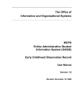
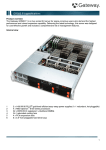
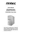
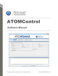
DVAA Series Disk Array
for DVR1 Series
Digital Video Recorder
Installation Instructions
Eng
Philips
Communication,
Security & Imaging
Warning!
To prevent fire and electronic shock, do not expose this product to rain or moisture.
The lightning flash with the arrowhead
symbol, within an equilateral triangle, is
intended to alert th e user to the presence of
uninsulated “dangerous voltage” within the
products enclosure that may be of sufficient
magnitude to constitute a risk of electric
shock to persons.
The exclamation point, within an equilateral
triangle, is intended to alert the user to the
presence of important operating and
maintenance (servicing) instructions in the
literature accompanying the product.
!
Caution!
To prevent electric shock, do not remove cover. No user
serviceable components inside. Refer servicing to qualified
service personnel.
Caution! Lithium Battery
Danger of explosion if battery is incorrectly
replaced. Replace only with the same or
equivalent type recommended by the
manufacturer.
!
Attention
This product contains a recyclable lithium battery.
It may be illegal to dispose of this battery
improperly under local, state, or federal laws.
Check with your local waste management officials
for disposal and recycling options.
Caution! Electrostatic-Sensitive Device!
Use proper CMOS and MOSFET handing precautions, including approved
grounded wrists straps, etc., to avoid damage to this unit or its internal
components, from electric discharge.
Warning!
This equipment generates, uses and can radiate radio frequency energy, and if not
installed and used in accordance with the instructions in this manual, may cause
interference to radio communications. It has been tested and found to comply with the
limits for a Class A computing device pursuant to subpart J of part 15 of FCC rules which
are designed to provide reasonable protection against such interference when operated in
a commercial environment. This equipment has also been tested and found to comply with
the requirements for a CE Class A device and TUV safety standards.
Operation of this equipment in a residential area may cause interference, in which case the
user is required to take all measures that are necessary, at the user's expense, to correct
the interference.
1
1
1.1
1.2
1.3
1.4
1.5
1.6
1.7
2
2.1
2.2
2.3
3
3.1
3.2
3.3
3.4
3.5
3.6
3.7
4
5
Installation....................................................................... 3
Product Description........................................................................................3
Unpacking........................................................................................................3
Installation Environment................................................................................3
Rear Panel Diagram.......................................................................................4
Connections.....................................................................................................4
Power-Up .........................................................................................................5
Front Panel Indicators ....................................................................................5
DVAA/DVR1 Installation ................................................ 7
Connecting to the DVR1................................................................................7
Configuring the DVR1....................................................................................7
DVR1 Archiving Limitations:.........................................................................7
Adding Hard Drives ........................................................ 8
Opening The DVAA........................................................................................8
Identifying The Components .........................................................................8
Mounting The Hard Drives ............................................................................9
Configuring Master/Slave ..............................................................................9
Connecting Hard Drives...............................................................................10
Powering Hard Drives..................................................................................10
Compatible Hard Drives...............................................................................11
Warranty.........................................................................12
Factory Service.............................................................12
2
1
Installation
1.1 Product Description
The DVAA is a large, economical, hard drive based storage/archive device. It is
available with 4 hard disk drives (model DVAA0412) or 8 hard disk drives (model
DVAA0812). The DVAA0412 unit can later be repopulated with additional hard
drives.
1.2 Unpacking
Check the package and contents for visible damage. If any components are
damaged or missing, do not attempt to use the unit. Contact the supplier
immediately. If the unit must be returned, it must be shipped in the original
packaging.
Package Contents
•
The DVAA unit.
•
US & EU Power Cables.
•
•
SCSI cable (Part No. CDW138264)
This Installation Guide
•
IDE Hard Drive Power Cables (Not provided with the DVAA0812)
•
IDE Hard Drive Ribbon cables (Not provided with the DVAA0812)
•
Hard Drive Fastening Screws. (Not provided with the DVAA0812)
1.3 Installation Environment
Power: Ensure that the site’s AC power is stable and within the rated voltage of
the disk array. If the site’s AC power is likely to have spikes or dips, use power
line conditioning or an Uninterruptable Power Supply.
Ventilation: Ensure that the location is well ventilated. Do not obstruct the
cooling vents or fans.
Temperature: Insure the ambient temperature is within 0 to 40o Centigrade (32 o
to 104 o Fahrenheit).
Do not install this unit on top of other hot equipment.
Moisture: Do not expose the unit to rain or moisture.
3
1.4 Rear Panel Diagram
1
2
3
4
5
6
7
8
Rear Panel Elements
1.
2.
Cooling Fan: Do not obstruct.
Power Connector, Voltage Selector and On/Off Switch
3.
4.
5.
6.
7.
IEEE-1394 Firewire Ports 1 and 2*
10/100 Ethernet Port*
SCSI Ports 1 and 2
Dip Switches*
RS-232 Port
8.
Alarm Out Relay Connection*
1.5 Connections
NOTE:
* The Ethernet, Aux dip switch, Alarm output and IEEE-1394 Firewire ports are
reserved for future upgrade.
SCSI Ports 1 and 2
Connect to either SCSI port. Using
the dip switches on the rear of the
unit, set SCSI Termination and
SCSI Power to On.
Connector: 50 pin, high density SCSI-2.
Gender (on unit): Female.
SCSI ID: 0.
The unit does not currently support multiple SCSI device connections.
RS-232 Port
The RS-232 port is used for flash
upgrading the DVAA operating
system software.
Connector Type: DB-9.
Gender (on unit): Male.
Cable Required: Null Modem.
4
DB-9 Pin Configuration For RS-232 Port
Pin
Use
Pin
Use
1
DCD
6
Not Connected
2
RX
7
RTS
3
TX
8
CTS
4
Not Connected
9
Not Connected
5
Ground
1.6 Power-Up
Select the correct voltage before supplying power to
the unit.
Use the voltage selector switch located on the rear panel
of the unit, between the power connector and the On/Off
Switch.
Caution: Applying incorrect voltage could damage unit.
Once the correct voltage has been selected and all
connections have been made, apply power to the unit.
1.7 Front Panel Indicators
Disk Array
HARDDRIVESTATUS
POWER
1
2
3
4
5
ACTIVITY
6
7
8
LINK
READ
WRITE
100
ETHERNET
Hard Drive Status Indicators (Green Lights)
Light On: Drive present and operating.
Light Flashing: Drive present, error detected.
Light Off: No drive present, or drive damaged beyond recognition.
5
Hard Drive Activity Indicators (Red Lights)
The light blinks when the drive is being accessed (read or write).
Ethernet Indicators
Reserved for future use.
LCD Display
Once power-up is complete, the LCD will display the total disk storage capacity
of the unit.
Key Pad
Reserved for future use.
6
2
DVAA/DVR1 Installation
The Philips DVAA Disk Array is only compatible with the DVR1 series
digital video recorder.
2.1 Connecting to the DVR1
1) Connect the SCSI cable from the DVR1 to the DVAA series
disk array.
2) Apply Power to the DVAA and wait 20 seconds
3) Apply Power to the DVR1
2.2 Configuring the DVR1
1) Configure the DVR1 Background Archive to ON (ARCHIVE
SETUP > BACKGROUND ARCHIVE > ON)
2) Configure the DVR1 Archiving Overwrite mode for
Continuous Overwrite (ARCHIVE SETUP > ARCHIVE
OVERWRITE MODE > CONTINUOUS OVERWRITE)
•
Note: The Disk Array does not support the other Overwrite
Modes.
Optional:
3) Configure the Archive status to ON (DISPLAY SETTINGS >
ARCHIVE STATUS > ON). This will display “Archive Not
Connected” if the Archive Device is not communicating or
working properly.
2.3 DVR1 Archiving Limitations:
1.
The DVR1 cannot Background archive images greater than
20 ips (NTSC) 17 ips (PAL). The DVR1 can selectively
archive video recorded at any speed.
2.
The DVR1 cannot properly playback video at speeds greater
than 20 IPS (NTSC), 17 IPS (PAL). It is recommended to first
restore the video to the DVR1’s hard drive (ARCHIVE SETUP
> RESTORE FROM ARCHIVE).
7
3.
3
Before restoring archive data from the disk array (searching
the disk array’s indexes), the DVR1 must stop recording.
Adding Hard Drives
This section is required if your unit was shipped without hard drives installed, or if
the user needs to replace a faulty drive.
Caution: Do not allow any metal object to contact the motherboard. Do not
allow loose screws to become lost inside the DVAA chassis. Wear an Electro
Static Discharge protection device any time work is being performed inside the
unit.
3.1 Opening The DVAA
Before removing the cover, turn off the unit and unplug it. Using a Phillips -head
screwdriver, carefully remove the twelve screws fastening the lid to the chassis.
Save the screws and use them to refasten the lid when finished.
3.2 Identifying The Components
Complete Internal Overview
Power
Supply
Mother
Board
Disk
Array
8
Motherboard Overview
Power
Supply
Load
Resistors
Jumpers
IDE
Connectors
IDE Power
Connectors
3.3 Mounting The Hard Drives
First remove the hard drive support bracket. Orient the hard drive so that the IDE
Power Connector is near the bottom of the chassis and facing the motherboard.
Populate the drive array in order, starting from the left.
Fasten the drive in place using the supplied screws. Fasten each drive using two
screws through the bottom of the chassis. Attach the Hard Drive Support
Bracket then fasten the hard drives to the bracket using the screws.
3.4 Configuring Master/Slave
IDE Connector #3
IDE Connector #4
Disk 4
Slave
Disk 3
Master
Disk 2
Slave
IDE Connector #2
Disk 5
Master
IDE Connector #1
Disk 1
Master
Hard drives are connected in pairs to
each of the four IDE connectors. Each
pair of hard drives must have a Master
and a Slave. Configure the
Master/Slave setting on each hard
drive individually using the jumpers
provided with the drive. Use the
diagram located on the hard drive to
determine the proper jumper
configuration.
If a single drive is connected to an IDE
connector, it must be configured as a
Master.
When configuring the jumpers on the hard drive, select 16 Heads, Master or
Slave.
9
3.5 Connecting Hard Drives
Use an IDE cable to connect drives as shown in the previous diagram. When
attaching the IDE connector, make sure the connectors are oriented properly.
Connecting To The Motherboard
The red stripe on the connection ribbon
should connect nearest the Pin 1 indicator
on the motherboard.
Pin 1
Indicator
Connecting To The Hard Drive
The red stripe on the connection ribbon
should connect near the jumpers on the hard
drive.
Pin 1 Near
Jumpers
3.6 Powering Hard Drives
Connect the hard
drives as shown in
the diagram.
Mother Board
10
Disk 8
Disk 7
Disk 6
Disk 5
Disk 4
Disk 3
Disk 2
Disk 1
Power Supply
3.7 Compatible Hard Drives
The following is a list of hard drives that are compatible with the DVAA series
disk array.
Maxtor Drives
Model
Part Number
Size
Vulcan
4W030H2
30GB
Vulcan
4W100H2
100GB
Romulus
4D120J6
120 GB
Galaxy
4K040H2
40GB
Galaxy
4K080H2
80GB
Model
Part Number
Size
IBM
07N3925
30GB
IBM
07N3935
75GB
IBM Drives
11
4
Warranty
This product offers a 3year warranty. The warranty does not cover hard
drives not installed by the factory and does not cover damages that may
occur due to improper hard drive installation.
5
Factory Service
Refer all Service to qualified personnel.
Contact the local Philips representative for service.
Service Centers:
USA: Ph: 800-366-2283
Central & S. America: 805-967-7917 (fax: 800-366-1329)
(e-mail: [email protected])
Canada: 514-738-2434 (fax: 514-738-8480)
Europe and Asia: 011-32-1-440-0711 (fax: 011-32-1-442-7054)
12
3935 890 41711 02-19
© 2002 by Bosch Security Systems, Inc.
All Rights Reserved. Philips ® is a registered trademark of
Philips Electronics N. A. Corp.
Data subject to change without notice