1
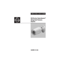
INSTALLATION/OPERATION
400 Series Flat Panel
LCD Monitors
C2927M-C (12/06)
Contents
Important Safety Instructions . . . . . . . . . . . . . . . . . . . . . . . . . . . . . . . . . . . . . . . . . . . . . . . . . . . . . . . . . . . . . . . . . . . . . . . . . . . . . . . . . . . . . . . . . . . . 4
Regulatory Notices . . . . . . . . . . . . . . . . . . . . . . . . . . . . . . . . . . . . . . . . . . . . . . . . . . . . . . . . . . . . . . . . . . . . . . . . . . . . . . . . . . . . . . . . . . . . . . . . . . . . 5
Description . . . . . . . . . . . . . . . . . . . . . . . . . . . . . . . . . . . . . . . . . . . . . . . . . . . . . . . . . . . . . . . . . . . . . . . . . . . . . . . . . . . . . . . . . . . . . . . . . . . . . . . . . . 6
Models . . . . . . . . . . . . . . . . . . . . . . . . . . . . . . . . . . . . . . . . . . . . . . . . . . . . . . . . . . . . . . . . . . . . . . . . . . . . . . . . . . . . . . . . . . . . . . . . . . . . . . . . . 6
Package Contents . . . . . . . . . . . . . . . . . . . . . . . . . . . . . . . . . . . . . . . . . . . . . . . . . . . . . . . . . . . . . . . . . . . . . . . . . . . . . . . . . . . . . . . . . . . . . . . . 7
Installation . . . . . . . . . . . . . . . . . . . . . . . . . . . . . . . . . . . . . . . . . . . . . . . . . . . . . . . . . . . . . . . . . . . . . . . . . . . . . . . . . . . . . . . . . . . . . . . . . . . . . . . . . . 8
Desktop Stand . . . . . . . . . . . . . . . . . . . . . . . . . . . . . . . . . . . . . . . . . . . . . . . . . . . . . . . . . . . . . . . . . . . . . . . . . . . . . . . . . . . . . . . . . . . . . . . . . . . 8
Rear Panel Connectors . . . . . . . . . . . . . . . . . . . . . . . . . . . . . . . . . . . . . . . . . . . . . . . . . . . . . . . . . . . . . . . . . . . . . . . . . . . . . . . . . . . . . . . . . . . . . 8
Video and Power Connections . . . . . . . . . . . . . . . . . . . . . . . . . . . . . . . . . . . . . . . . . . . . . . . . . . . . . . . . . . . . . . . . . . . . . . . . . . . . . . . . . . . . . . 10
Operation . . . . . . . . . . . . . . . . . . . . . . . . . . . . . . . . . . . . . . . . . . . . . . . . . . . . . . . . . . . . . . . . . . . . . . . . . . . . . . . . . . . . . . . . . . . . . . . . . . . . . . . . . . 12
Installing Remote Control Batteries . . . . . . . . . . . . . . . . . . . . . . . . . . . . . . . . . . . . . . . . . . . . . . . . . . . . . . . . . . . . . . . . . . . . . . . . . . . . . . . . . 12
Front Panel Controls . . . . . . . . . . . . . . . . . . . . . . . . . . . . . . . . . . . . . . . . . . . . . . . . . . . . . . . . . . . . . . . . . . . . . . . . . . . . . . . . . . . . . . . . . . . . . . 13
Remote Control Functions . . . . . . . . . . . . . . . . . . . . . . . . . . . . . . . . . . . . . . . . . . . . . . . . . . . . . . . . . . . . . . . . . . . . . . . . . . . . . . . . . . . . . . . . . 14
OSD Control Menus . . . . . . . . . . . . . . . . . . . . . . . . . . . . . . . . . . . . . . . . . . . . . . . . . . . . . . . . . . . . . . . . . . . . . . . . . . . . . . . . . . . . . . . . . . . . . . 15
Video Menu (Video Mode) . . . . . . . . . . . . . . . . . . . . . . . . . . . . . . . . . . . . . . . . . . . . . . . . . . . . . . . . . . . . . . . . . . . . . . . . . . . . . . . . . . . . 15
Video Menu (VGA Mode) . . . . . . . . . . . . . . . . . . . . . . . . . . . . . . . . . . . . . . . . . . . . . . . . . . . . . . . . . . . . . . . . . . . . . . . . . . . . . . . . . . . . . 16
Audio Menu . . . . . . . . . . . . . . . . . . . . . . . . . . . . . . . . . . . . . . . . . . . . . . . . . . . . . . . . . . . . . . . . . . . . . . . . . . . . . . . . . . . . . . . . . . . . . . . 16
Screen Menu (Video Mode) . . . . . . . . . . . . . . . . . . . . . . . . . . . . . . . . . . . . . . . . . . . . . . . . . . . . . . . . . . . . . . . . . . . . . . . . . . . . . . . . . . . 16
Screen Menu (VGA Mode) . . . . . . . . . . . . . . . . . . . . . . . . . . . . . . . . . . . . . . . . . . . . . . . . . . . . . . . . . . . . . . . . . . . . . . . . . . . . . . . . . . . . 17
Source Menu (Video Mode) . . . . . . . . . . . . . . . . . . . . . . . . . . . . . . . . . . . . . . . . . . . . . . . . . . . . . . . . . . . . . . . . . . . . . . . . . . . . . . . . . . . 17
Source Menu (VGA Mode) . . . . . . . . . . . . . . . . . . . . . . . . . . . . . . . . . . . . . . . . . . . . . . . . . . . . . . . . . . . . . . . . . . . . . . . . . . . . . . . . . . . . 18
Option Menu . . . . . . . . . . . . . . . . . . . . . . . . . . . . . . . . . . . . . . . . . . . . . . . . . . . . . . . . . . . . . . . . . . . . . . . . . . . . . . . . . . . . . . . . . . . . . . . 18
Menu Default Values . . . . . . . . . . . . . . . . . . . . . . . . . . . . . . . . . . . . . . . . . . . . . . . . . . . . . . . . . . . . . . . . . . . . . . . . . . . . . . . . . . . . . . . . . . . . . 19
Cleaning . . . . . . . . . . . . . . . . . . . . . . . . . . . . . . . . . . . . . . . . . . . . . . . . . . . . . . . . . . . . . . . . . . . . . . . . . . . . . . . . . . . . . . . . . . . . . . . . . . . . . . . 19
Supported Input Modes . . . . . . . . . . . . . . . . . . . . . . . . . . . . . . . . . . . . . . . . . . . . . . . . . . . . . . . . . . . . . . . . . . . . . . . . . . . . . . . . . . . . . . . . . . . . . . . 20
Specifications . . . . . . . . . . . . . . . . . . . . . . . . . . . . . . . . . . . . . . . . . . . . . . . . . . . . . . . . . . . . . . . . . . . . . . . . . . . . . . . . . . . . . . . . . . . . . . . . . . . . . . . 21
List of Illustrations
1
2
3
4
5
6
7
Rear Panel Connectors . . . . . . . . . . . . . . . . . . . . . . . . . . . . . . . . . . . . . . . . . . . . . . . . . . . . . . . . . . . . . . . . . . . . . . . . . . . . . . . . . . . . . . . . . . . . . 7
Front Panel Controls . . . . . . . . . . . . . . . . . . . . . . . . . . . . . . . . . . . . . . . . . . . . . . . . . . . . . . . . . . . . . . . . . . . . . . . . . . . . . . . . . . . . . . . . . . . . . . . 8
Main Menu . . . . . . . . . . . . . . . . . . . . . . . . . . . . . . . . . . . . . . . . . . . . . . . . . . . . . . . . . . . . . . . . . . . . . . . . . . . . . . . . . . . . . . . . . . . . . . . . . . . . . . 9
Display Adjust Menu . . . . . . . . . . . . . . . . . . . . . . . . . . . . . . . . . . . . . . . . . . . . . . . . . . . . . . . . . . . . . . . . . . . . . . . . . . . . . . . . . . . . . . . . . . . . . 10
Color Temperature Menu . . . . . . . . . . . . . . . . . . . . . . . . . . . . . . . . . . . . . . . . . . . . . . . . . . . . . . . . . . . . . . . . . . . . . . . . . . . . . . . . . . . . . . . . . . 10
OSD Adjust Menu . . . . . . . . . . . . . . . . . . . . . . . . . . . . . . . . . . . . . . . . . . . . . . . . . . . . . . . . . . . . . . . . . . . . . . . . . . . . . . . . . . . . . . . . . . . . . . . . 11
Audio Control Menu . . . . . . . . . . . . . . . . . . . . . . . . . . . . . . . . . . . . . . . . . . . . . . . . . . . . . . . . . . . . . . . . . . . . . . . . . . . . . . . . . . . . . . . . . . . . . . 11
List of Tables
A Video Coaxial Cable Requirements . . . . . . . . . . . . . . . . . . . . . . . . . . . . . . . . . . . . . . . . . . . . . . . . . . . . . . . . . . . . . . . . . . . . . . . . . . . . . . . . . . 10
C2927M-C (12/06)
3
Important Safety Instructions
1. Read these instructions.
2. Keep these instructions.
3. Heed all warnings.
4. Follow all instructions.
5. Do not use this apparatus near water.
6. Clean only with dry cloth.
7. Do not block any ventilation openings. Install in accordance with the manufacturer’s instructions.
8. Do not install near any heat sources such as radiators, heat registers, stoves, or other apparatus (including amplifiers) that produce heat.
9. Do not defeat the safety purpose of the polarized or grounding-type plug. A polarized plug has two blades with one blade wider than the
other. A grounding plug has two blades and a third grounding prong. The wide blade or the third prong are provided for your safety. If the
provided plug does not fit into your outlet, consult an electrician for replacement of the obsolete outlet.
10. Protect the power cord from being walked on or pinched particularly at plugs, convenience receptacles, and the points where they exit from
the apparatus.
11. Only use attachments/accessories specified by the manufacturer.
12. Use only with the cart, stand, tripod, bracket, or table specified by the manufacturer, or sold with the apparatus. When a cart is used, use
caution when moving the cart/apparatus combination to avoid injury from tip-over.
13. Refer all servicing to qualified service personnel. Servicing is required when the apparatus has been damaged in any way, such as powersupply cord or plus is damaged, liquid has been spilled or objects have fallen into the apparatus, the apparatus has been exposed to rain or
moisture, does not operate normally, or has been dropped.
14. Apparatus shall not be exposed to dripping or splashing and that no objects filled with liquids, such as vases shall be placed on the
apparatus.
15. WARNING: To reduce the risk of fire or electric shock, do not expose this apparatus to rain or moisture.
16. Installation should be done only by qualified personnel and conform to all local codes.
17. Unless this unit is specifically marked as NEMA Type 3, 3R, 3S, 4, 4X, 6, or 6P enclosure, it is designed for indoor use only and it must not
be installed where exposed to rain and moisture.
18. Use only installation methods and materials capable of supporting four times the maximum specified load.
19. Only use replacement parts recommended by Pelco.
20. Avoid touching the screen directly with your fingers as the oils from your skin may be difficult to remove from the LCD.
21. Do not apply direct pressure on the screen.
22. Keep the monitor in a dust-free environment and away from strong electromagnetic fields.
23. Do not use attachments, such as mounts, that are not recommended by Pelco. They may be hazardous.
24. Do not place the monitor on an unstable stand, bracket, or mount. The unit may fall, causing serious damage to the unit or injury to a
person. Only use mounts recommended by Pelco.
25. A CCC-approved power cord must be used to power this equipment when used in China.
The product and/or manual may bear the following marks:
This symbol indicates that dangerous voltage constituting a risk of electric shock is present
within this unit.
This symbol indicates that there are important operating and maintenance instructions in
the literature accompanying this unit
4
CAUTION:
RISK OF ELECTRIC SHOCK.
DO NOT OPEN.
C2927M-C (12/06)
Regulatory Notices
This device complies with Part 15 of the FCC Rules. Operation is subject to the following two conditions: (1) this device may not cause harmful
interference, and (2) this device must accept any interference received, including interference that may cause undesired operation.
RADIO AND TELEVISION INTERFERENCE
This equipment has been tested and found to comply with the limits of a Class B digital device, pursuant to Part 15 of the FCC Rules. These limits
are designed to provide reasonable protection against harmful interference in a residential installation. This equipment generates, uses, and can
radiate radio frequency energy and, if not installed and used in accordance with the instructions, may cause harmful interference to radio
communications. However there is no guarantee that the interference will not occur in a particular installation. If this equipment does cause
harmful interference to radio or television reception, which can be determined by turning the equipment off and on, the user is encouraged to try
to correct the interference by one or more of the following measures:
•
Reorient or relocate the receiving antenna.
•
Increase the separation between the equipment and the receiver.
•
Connect the equipment into an outlet on a circuit different from that to which the receiver is connected.
•
Consult the dealer or an experienced radio/TV technician for help.
You may also find helpful the following booklet, prepared by the FCC: “How to Identify and Resolve Radio-TV Interference Problems.” This
booklet is available from the U.S. Government Printing Office, Washington D.C. 20402.
Changes and Modifications not expressly approved by the manufacturer or registrant of this equipment can void your authority to operate this
equipment under Federal Communications Commission’s rules.
This Class B digital apparatus complies with Canadian ICES-003.
Cet appareil numérique de la classe B est conforme à la norme NMB-003 du Canada.
C2927M-C (12/06)
5
Description
The 400 Series high performance LCD monitors are designed specifically for the security industry and provide high quality display of video or
computer signals using multiple inputs. These 15-, 17-, and 19-inch monitors use a color, thin film transfer (TFT) active matrix LCD panel that
automatically adapts to the appropriate input resolution.
The 400 Series is distinguished by many performance-enhancing features such as a 3-D digital comb filter, DVI (digital visual interface) input,
picture-in-picture (PIP), and USB hub. The 3-D digital comb filter with deinterlacing provides the most accurate processing of composite video
signals for a sharper, cleaner picture. DVI ensures that digital signals remain uncompressed (in their true digital form) without the distortion that
may occur through analog-to-digital conversion. The PIP feature allows for simultaneous viewing of surveillance camera images and PC screens.
A USB hub provides a single input with three outputs adding to the overall flexibility of the high performance 400 Series.
The 400 Series provides two looping composite (BNC) inputs and outputs and one S-Video input and output. Additionally, these models provide
an analog VGA input to support the use of DVRs (digital video recorders) and PC applications. This multimode functionality—combined with the
high performance features, quick panel response time to minimize ghosting in motion video, ergonomic design, autoranging internal power
supply, and low power consumption—makes the 400 Series the optimal replacement for conventional CRT monitors.
The 400 Series features a folding picture frame-style desktop stand, optional rack mount kits, and VESA®-compliant mounting holes to easily
adapt to any VESA-compliant wall mount.
These monitors automatically detect and display the correct video format (NTSC or PAL) and are powered by an internal autoranging power
supply.
The 400 Series uses four long-life CCFT (cold cathode florescent tube) backlights to maintain the brightness level over time, eliminating the
brightness degradation common in aging CRT monitors.
Adjustments of standard monitor display parameters are made using user-friendly, on-screen menus and front panel controls.
MODELS
PMCL415
PMCL417
PMCL419
6
15-inch (381 mm) active TFT LCD monitor
17-inch (432 mm) active TFT LCD monitor
19-inch (483 mm) active TFT LCD monitor
C2927M-C (12/06)
PACKAGE CONTENTS
1
1
1
1
1
1
1
2
1
15-, 17-, or 19-inch TFT LCD monitor
VGA cable with 15-pin, D-sub connector
US standard power cable
EU standard power cable
DVI cable
USB cable (Type A to B)
Remote control unit
AA batteries
Installation/Operation manual
VGA CABLE WITH 15-PIN,
D-SUB CONNECTOR
TFT LCD MONITOR
INSTALLATION
OPERATION MANUAL
REMOTE CONTROL UNIT
2 AA BATTERIES
US STANDARD
POWER CABLE
DVI CABLE
EU STANDARD
POWER CABLE
USB CABLE (TYPE A TO B)
Figure 1. Parts List Illustration
C2927M-C (12/06)
7
Installation
The monitor can be placed on any flat surface (desk or table), or it can be rack mounted or wall mounted.
NOTE: Only use a recommended rack mount or wall mount kit, such as the PMCL-RM15, PMCL-RM17, PMCL-RM19, or PMCL-WM. To rackmount or wall-mount the monitor, follow the instructions supplied with the mount kit. Refer to manual C2220M for the rack mount kit instructions
or C2219M for the wall mount kit instructions.
DESKTOP STAND
You can manually adjust the 400 Series monitor to the viewing angle you want by repositioning the foot stand on the back of the monitor.
REAR PANEL CONNECTORS
�
2.0
�
�
S-VIDEO
OUT
IN
AUDIO-IN
L
R
L
R
AUDIO-OUT
VIDEO 1
OUT
IN
OUT
IN
VIDEO 2
AC IN
��
�
DC OUT
DC IN
��
VGA
�
�
��
��
��
��
��
DVI
�
��
Figure 2. Rear Panel Connectors
8
C2927M-C (12/06)
1. AC IN: Can be connected to a 100-240 VAC, 50/60 Hz source.
2. DC OUT: Can output 12 VDC, 0.5 A (continuous), 50/60 Hz.
3. DC IN: Can be connected to an external 12 VDC, 5 A source.
4. VGA IN: Can be connected to the VGA cable (supplied).
5. DVI IN: Can be connected to the DVI cable (supplied).
6. USB: The USB-A 2.0 downstream port. It can be used to connect to such peripherals as a USB camera or USB key.
7. USB: The USB-A 2.0 downstream dual port. It can be used to connect to such peripherals as a USB camera or USB key.
8. USB: The USB-B 2.0 upstream port. It can be used to connect to a PC using the USB cable (supplied).
9. S-VIDEO IN: Can input an S-video signal by DIN socket.
10. S-VIDEO OUT: Can output an S-video signal by DIN socket. This socket is the loop-through output (maximum of one looping operation only
is recommended).
11. AUDIO IN: These RCA sockets can be connected to audio outputs (White terminal, Reed terminal).
12. AUDIO OUT: These RCA sockets can output sound to other speakers. This socket is the loop-through output.
13. VIDEO 1 IN/OUT: The IN BNC socket can be connected to a composite video output. The OUT BNC socket is the loop-through output.
The input is automatically terminated if the loop-through output is not used.
14. VIDEO 2 IN/OUT: The IN BNC socket can be connected to a composite video output. The OUT BNC socket is the loop-through output.
The input is automatically terminated if the loop-through output is not used.
15. Speakers: The unit has two built-in speakers.
C2927M-C (12/06)
9
VIDEO AND POWER CONNECTIONS
Refer to Figure 2 for video, audio, power, and other connections.
1. Connect the video cable (refer to Table A for video coaxial requirements.)
a.
Connect video cables as follows, depending on the input source.
•
•
•
•
b.
For composite, connect to the BNC video input labeled VIDEO 1 IN on the back panel of the monitor. If the installation requires a
second video input, connect a video cable to the BNC video input labeled VIDEO 2 IN. (Inputs are auto-terminating. If the
correlating output is not used, the input will be terminated.)
For S-Video, connect to the input labeled S-VIDEO IN on the back panel of the monitor. (Inputs are auto-terminating. If the
correlating output is not used, the input will be terminated.)
For VGA, connect to the input labeled VGA IN on the back panel of the monitor.
For DVI, connect to the input labeled DVI IN on the back panel of the monitor.
If you intend on using the PIP feature, you can connect video inputs in any of the following combinations:
•
•
One VGA input and one composite input.
One VGA input and one S-Video input.
Note the following when using PIP mode:
•
•
•
c.
If PIP is enabled when you connect a video input, auto detect will not function and the signal may not be synchronized.
If PIP is enabled in VGA or composite video mode, video menu adjustments affect the PIP and not the main screen.
DVI mode does not support PIP.
Looping operation only. Connect a video cable to the BNC video connector labeled VIDEO 1 OUT for composite video or connect the
video cable to the connector labeled S-VIDEO OUT for S-Video. If the installation requires a second composite video output, connect a
video cable to the BNC video output labeled VIDEO 2 OUT (refer to Figure 3 and Figure 4.)
NOTE: A maximum of three Lacs can be looped (except for S-Video, where only one loop is advised).
2. Connect peripherals, as desired. Connect USB cables to the downstream USB ports on the back of the monitor (refer to callout numbers 6
and 7 in Figure 2.)
3. Connect to a PC, as desired. Connect a USB cable (supplied) to the upstream USB port on the back of the monitor (refer to callout number 8
in Figure 2.)
4. Connect audio, as desired. The monitor has built-in speakers but can also loop out to an external speaker. Connect the audio input cables to
the connections labeled AUDIO IN on the back panel of the monitor. Connect one end of the audio output cables to the connections labeled
AUDIO OUT on the back panel of the monitor and the other end to a speaker (refer to Figure 3 and Figure 4 for looping connections.)
5. Connect power. Do one of the following:
•
•
Plug the provided power cord into the AC IN connection on the back panel. Plug the other end of the cord into a power receptacle.
If using an external power supply (not included), plug one end of the power supply into the DC IN connector on the back panel of the
monitor. Plug the other end of the power supply into a power receptacle.
Table A. Video Coaxial Cable Requirements
Cable Type*
Maximum Distance
RG59/U
750 ft (229 m)
RG6/U
1,000 ft (305 m)
RG11/U
1,500 ft (457 m)
*Minimum cable requirements:
75 ohms impedance. All-copper center conductor.
95% braided copper shield.
10
C2927M-C (12/06)
PMCL400
2.0
DVR
CAMERA
S-VIDEO
IN
OUT
AUDIO IN
AUDIO
L
R
L
R
AUDIO SOURCE
AUDIO OUT
DVR
OUT
CAMERA
VIDEO 1
IN
IN
OUT
DVR
VIDEO 2
CAMERA
Figure 3. Looping Operation: One Monitor with External Video Equipment
PMCL400
PMCL400
PMCL400
2.0
2.0
2.0
DVR
S-VIDEO
S-VIDEO
IN
OUT
AUDIO IN
AUDIO
IN
OUT
AUDIO IN
AUDIO IN
L
R
L
R
L
R
L
R
L
R
L
R
AUDIO SOURCE
AUDIO OUT
DVR
CAMERA
S-VIDEO
IN
OUT
OUT
VIDEO 1
OUT
VIDEO 2
AUDIO OUT
IN
OUT
IN
OUT
VIDEO 1
AUDIO OUT
IN
OUT
IN
OUT
VIDEO 2
VIDEO 1
CAMERA
IN
IN
VIDEO 2
Figure 4. Looping Operation: Maximum of Three Monitors with External Video Equipment
NOTE: Looping more than three 400 Series monitors is not recommended.
C2927M-C (12/06)
11
Operation
INSTALLING REMOTE CONTROL BATTERIES
PRESS AND SLIDE TO REMOVE
Figure 5. Battery Installation
Refer to Figure 5 for the following procedure.
1. Open and remove the battery cover on the back of the remote control.
2. Install two AA size batteries (supplied). Match the + and – signs on the batteries to the signs on the battery compartment.
3. Close the battery cover. Make sure the lock snaps closed.
WARNING:
12
•
Dispose of batteries in a designated disposal area. Do not throw batteries into a fire.
•
Do not mix battery types.
•
Remove dead batteries immediately to prevent battery acid from leaking into the battery compartment.
•
Remove the batteries if you do not intend to use the remote control for a long period of time.
C2927M-C (12/06)
FRONT PANEL CONTROLS
CH
���
���
�
�
Figure 6. Front Panel Controls
1. Selects the input signal and swaps the main and PIP displays when PIP is active.
2. Decreases the value of a selected menu item and accesses the brightness control when no PIP or menu is active. It can reposition PIP when
PIP is active.
3. Increases the value of a selected menu item, and it enables or disables PIP when no menu is active.
4. Moves the highlighter downward through a menu.
5. Moves the highlighter upward through a menu.
6. Opens the main menu when no menu is active, and it selects a highlighted menu item when a menu is active.
NOTE: This button has a two-second delay in opening the menu when pressed. It also functions as a lock/unlock button. When pressed for
five seconds, a red box containing the words KEY LOCKED or KEY UNLOCK appears. When KEY LOCKED is active, all front panel
controls (including the power button and controls on the remote control) are disabled. Activate KEY UNLOCK by pressing the button for five
seconds to regain control.
7. Turns on or off power to the monitor.
8. Receives the remote control signal. This is the infrared sensor for the remote control unit.
C2927M-C (12/06)
13
REMOTE CONTROL FUNCTIONS
�
�
�
�
�
��
��
��
��
PIP
SWAP LOCATE
CH
VOL
�
�
�
�
Figure 7. Remote Control Functions
1. Turns on or off power to the monitor.
2. Selects the previous channel.
3. Selects the next channel.
4. Increases the audio volume.
5. Decreases the audio volume.
6. Moves the PIP location to the next location (upper left, upper right, lower right, lower left, middle).
7. Swaps the PIP image with the main image or the main image with the PIP image.
8. Selects the PIP function.
9. Moves the highlighter upward through a menu.
10. Decreases the value of a selected menu item.
11. Enters the OSD menu and submenus, and it selects items.
12. Moves the highlighter downward through a menu.
13. Increases the value of a selected menu item.
14
C2927M-C (12/06)
OSD CONTROL MENUS
Unless otherwise noted, the menus are the same for the PMCL415, PMCL417, and PMCL419. Since different options are available for
different input types, some menus have a video mode and a VGA mode. Some options may be unavailable and are grayed out.
NOTE: There is no reset feature to return the monitor to factory defaults.
To use the menus:
1. Press the menu button to access the Main menu.
2. Use the up and down arrow buttons to highlight a selection.
3. Press the menu button to select an item.
4. Use the left and right arrow buttons to adjust the setting on a selected item.
VIDEO MENU (VIDEO MODE)
50
VIDEO MENU
Contrast
50
AUDIO MENU
Brightness
50
SCREEN MENU
Color
50
SOURCE MENU
Tint
10
OPTION MENU
Sharpness
03
EXIT MENU
Noise Reduction weak
50
50
Contrast
Brightness
Color
Tint
10
Return Menu
Sharpness
03
Off
Weak
Medium
Strong
Auto
Figure 8. Video Menu (Video Mode)
If PIP is active in video mode, these controls affect PIP and not the Main Display.
Video Menu (Video Mode) Field Definitions
Contrast: Adjusts the white level of the video screen image.
Brightness: Adjusts the black level of the video screen image.
Color: Adjusts the color saturation of the video signal.
Tint: Adjusts the range of color: green to red.
Sharpness: Adjusts the picture softer or sharper.
Noise Reduction: Adjusts the background noise of the video signal.
C2927M-C (12/06)
15
VIDEO MENU (VGA MODE)
VIDEO MENU
Contrast
AUDIO MENU
Brightness
SCREEN MENU
Color
SOURCE MENU
Tint
OPTION MENU
Sharpness
EXIT MENU
Noise Reduction weak
50
50
Contrast
Brightness
Return Menu
Figure 9. Video Menu (VGA Mode)
If PIP is active in VGA mode, these controls affect PIP and not the Main Display.
Video Menu (VGA Mode) Field Definitions
Contrast: Adjusts the white level of the video screen image.
Brightness: Adjusts the black level of the video screen image.
AUDIO MENU
VIDEO MENU
Volume
AUDIO MENU
Return Menu
20
Volume
SCREEN MENU
SOURCE MENU
OPTION MENU
EXIT MENU
Figure 10. Audio Menu
Audio Menu Field Definitions
Volume: Adjusts the volume level.
SCREEN MENU (VIDEO MODE)
VIDEO MENU
AUDIO MENU
SCREEN MENU
SOURCE MENU
OPTION MENU
EXIT MENU
Display Mode
Aspect
Clock
H Position
V Position
Phase
Smoothing
Auto Sync
Color Temperature DEFAULT
Return Menu
Aspect
Overscan
Figure 11. Screen Menu (Video Mode)
Screen Menu (Video Mode) Field Definitions
Display Mode: Select Aspect or Overscan mode.
Aspect mode on the 17- and 19-inch monitors gives a slightly elongated picture. In overscan mode some of the picture’s sides are lost but the vertical geometry is correct. These accommodations occur as the incoming 4:3 aspect ratio composite video [1024 x 768] is converted to the panel’s
native 5:4 ratio (1280 x 1024).
16
C2927M-C (12/06)
SCREEN MENU (VGA MODE)
VIDEO MENU
AUDIO MENU
SCREEN MENU
SOURCE MENU
OPTION MENU
EXIT MENU
Clock
50
Display Mode
Aspect
Clock
H Position
V Position
Phase
Smoothing
Auto Sync
Color Temperature DEFAULT
Return Menu
H Position
7
V Position
49
Phase
10
Smoothing
2
Auto Position
9300K
7500K
6500K
Default
Figure 12. Screen Menu (VGA Mode)
Screen Menu (VGA Mode) Field Definitions
Clock: Adjusts the horizontal size of the screen image.
H Position: Moves the screen image left or right.
V Position: Moves the screen image up or down.
Phase: Adjusts image distortion appearing as horizontal noise on the screen.
Smoothing: Enhances picture quality.
Auto Sync: Adjusts the screen image automatically for the best result.
Color Temperature: Adjusts the color temperature to 9300K, 7500K, 6500K or Default.
SOURCE MENU (VIDEO MODE)
VIDEO MENU
AUDIO MENU
Main Display Source: S-VIDEO
PIP Display Source: OFF
Return Menu
VGA
DVI
VIDEO-1
VIDEO-2
SVIDEO
SCREEN MENU
SOURCE MENU
VGA
OPTION MENU
EXIT MENU
OFF
Figure 13. Source Menu (Video Mode)
Source Menu (Video Mode) Field Definitions
Main Display Source: Select one: VGA, DVI, VIDEO-1, VIDEO-2, SVIDEO.
PIP Display Source: Select one: VGA or OFF. (Some choices will be shaded depending on your Main Display Source selection.) If PIP is active in
video mode, these controls affect PIP and not the Main Display.
C2927M-C (12/06)
17
SOURCE MENU (VGA MODE)
VIDEO MENU
AUDIO MENU
Main Display Source: VGA
PIP Display source: OFF
Return Menu
VGA
DVI
VIDEO-1
VIDEO-2
SVIDEO
SCREEN MENU
SOURCE MENU
OPTION MENU
VIDEO-1
VIDEO-2
SVIDEO
OFF
EXIT MENU
Figure 14. Source Menu (VGA Mode)
Source Menu (VGA Mode) Field Definitions
Main Display Source: Select one: VGA, DVI, VIDEO-1, VIDEO-2, SVIDEO.
PIP Display source: Select one: VIDEO-1, VIDEO-2, SVIDEO, OFF. (Some choices will be shaded depending on your Main Display Source selection.) If PIP is active in VGA mode, these controls affect PIP and not the Main Display.
OPTION MENU
VIDEO MENU
AUDIO MENU
SCREEN MENU
Menu Language
Menu Timeout 15 second
Menu Background opaque
Return Menu
SOURCE MENU
English
Simp-Chinese
Spanish
French
German
Return
15 second
20 second
25 second
30 second
40 second
OPTION MENU
EXIT MENU
Opaque
Transparent
Figure 15. Option Menu
Option Menu Field Definitions
Menu Language: Select a language for the OSD menu display: English, Chinese, Spanish, French, or German.
Menu Timeout: Select one for the OSD menu display: 15 second, 20 second, 25 second, 30 second, 40 second. Every “x” seconds, submenus
will exit until the menus are fully exited.
Menu Background: Select one for the OSD menu display: Opaque or Transparent.
18
C2927M-C (12/06)
MENU DEFAULT VALUES
Refer to the following default values if you need to manually return the monitor to the factory settings.
Video Menu
Contrast
Brightness
Color
Tint
Sharpness
Noise Reduction
50
50
50
0
2
Strong
Audio Menu
Volume
8
Screen Menu
Display Mode
Clock
H Position
V Position
Phase
Smoothing
Auto Sync
Color Temperature
Aspect
50
50
50
0
0
(no default setting)
9300K
Source Menu
Main Display Source
PIP Display Source
VGA
OFF
Option Menu
Menu Language
Menu Timeout
Menu Background
English
15
Opaque
Maintenance
If the quality of the picture is poor and cannot be improved by making adjustments on the front control panel, inspect all system connections and
cable runs.
WARNING: To reduce the risk of electrical shock, do not remove the cover or back of the monitor. No user-serviceable parts are inside.
Refer servicing to qualified personnel, or contact the Pelco Customer Service Department for assistance, 1-800-289-9100. Refer to the
Product Warranty and Return Information located on the inside back cover of this manual.
CLEANING
•
Gently wipe your screen with a clean camel hair brush or a soft, clean, lint-free cloth.
•
Gently apply pressure to the screen surface to clean the display.
•
Do not spray any liquid directly on the screen or the LCD monitor casing.
•
Chemical cleaners can damage the screen or the LCD monitor casing.
C2927M-C (12/06)
19
Supported Input Modes
20
Mode
Resolution
H Freq (kHz)
V Freq (Hz)
0
720 x 350
31.469
70.087
1
640 x 480
31.469
59.940
2
640 x 480
35.000
66.667
3
640 x 480
37.861
72.809
4
640 x 480
37.500
75.000
5
720 x 400
31.469
70.087
6
800 x 600
35.156
56.250
7
800 x 600
37.879
60.317
8
800 x 600
48.077
72.188
9
800 x 600
46.875
75.000
10
1024 x 768
48.363
60.004
11
1024 x 768
60.023
75.029
C2927M-C (12/06)
Specifications
MODELS
PMCL415
PMCL417
PMCL419
15-inch (381 mm) active TFT LCD monitor
17-inch (432 mm) active TFT LCD monitor
19-inch (483 mm) active TFT LCD monitor
GENERAL
LCD Panel Pixel Array
PMCL415
PMCL417, PMCL419
Panel Aspect Ratio
PMCL415
PMCL417, PMCL419
Viewing Area
PMCL415
PMCL417
PMCL419
Pixel Pitch
PMCL415
PMCL417
PMCL419
Brightness
PMCL415
PMCL417
PMCL419
Contrast Ratio
Backlight Type
Panel Lamp Life
Viewing Angle (H/V)
PMCL415
PMCL417
PMCL419
Tilt
Display Colors
PMCL415, PMCL417
PMCL419
Response Time
PMCL415
PMCL417
PMCL419
Speakers
Front Panel Controls
Indicators
1024 X 768, 75 Hz
1280 x 1024, 75 Hz (maximum VGA and DVI resolution is 1024 x 768)
4.3
4.3 composite, 5.4 VGA
304 x 228 mm
338 x 270 mm
376 x 301 mm
0.297 x 0.297
0.264 x 0.264
0.294 x 0.294
350 cd/m2
430 cd/m2
450 cd/m2
500:1
4 CCFL
40,000 hours
140°/125°
140°/130°
150°/130°
<10° to >45°
16.2 million
16.7 million
16 ms
8 ms
8 ms
2, integrated, 1 W each
Video input, menu (access and navigation), power
LED (power on/off), on-screen (“no signal”)
ELECTRICAL
Input Voltage
Power Consumption
PMCL415
PMCL417, PMCL419
Input Interfaces
Video*
Audio
Horizontal Frequency
Vertical Frequency
Sync Format
100-240 VAC, 50/60 Hz, internal power supply or 12 VDC external power supply (not included)
<50 W (on)
<60 W (on)
2 BNC, looping; 1 S-Video, looping; 1 VGA; 1 DVI; 1 PIP
1 (L/R), RCA, looping
30 kHz to 60 kHz
56 Hz to 75 Hz
NTSC/PAL autosensing
*Maximum VGA and DVI resolution is 1024 x 768 on PMCL417 and PMCL419.
C2927M-C (12/06)
21
PHYSICAL
Dimensions
PMCL415
PMCL417
PMCL419
Unit Weight
PMCL415
PMCL417
PMCL419
Shipping Weight
PMCL415
PMCL417
PMCL419
3.0" D x 13.7" W x 11.7" H (7.5 x 34.70 x 29.8 cm)
3.2" D x 15.0" W x 13.4" H (8.0 x 38.1 x 34.1 cm)
3.3" D x 16.6" W x 14.7" H (8.3 x 42.1 x 37.4 cm)
10.1 lb (4.6 kg)
13.1 lb (5.9 kg)
15.1 lb (6.9 kg)
14.0 lb (6.4 kg)
18.0 lb (8.2 kg)
20.0 lb (9.1 kg)
ENVIRONMENTAL
Operating Temperature
Storage Temperature
Operating Humidity
Storage Humidity
22
32° to 104°F (0° to 40°C)
-4° to 140°F (-20° to 60°C)
20% to 85%, noncondensing
5% to 90%, noncondensing
C2927M-C (12/06)
PRODUCT WARRANTY AND RETURN INFORMATION
WARRANTY
Pelco will repair or replace, without charge, any merchandise proved defective in material or
workmanship for a period of one year after the date of shipment.
Exceptions to this warranty are as noted below:
• Five years on FR/FT/FS Series fiber optic products and TW3000 Series unshielded twisted
pair transmission products.
• Three years on Spectra® IV products.
• Three years on Genex® Series products (multiplexers, server, and keyboard).
• Three years on Camclosure® and fixed camera models, except the CC3701H-2,
CC3701H-2X, CC3751H-2, CC3651H-2X, MC3651H-2, and MC3651H-2X camera models,
which have a five-year warranty.
• Three years on PMCL200/300/400 Series LCD monitors.
• Two years on standard motorized or fixed focal length lenses.
• Two years on Legacy®, CM6700/CM6800/CM9700 Series matrix, and DF5/DF8 Series fixed
dome products.
• Two years on Spectra III™, Esprit®, ExSite™, and PS20 scanners, including when used in
continuous motion applications.
• Two years on Esprit and WW5700 Series window wiper (excluding wiper blades).
• Two years (except lamp and color wheel) on Digital Light Processing (DLP®) displays.
The lamp and color wheel will be covered for a period of 90 days. The air filter is not
covered under warranty.
• Eighteen months on DX Series digital video recorders, NVR300 Series network video
recorders, and Endura™ Series distributed network-based video products.
• One year (except video heads) on video cassette recorders (VCRs). Video heads will be
covered for a period of six months.
• Six months on all pan and tilts, scanners or preset lenses used in continuous motion
applications (that is, preset scan, tour and auto scan modes).
Pelco will warrant all replacement parts and repairs for 90 days from the date of Pelco
shipment. All goods requiring warranty repair shall be sent freight prepaid to Pelco, Clovis,
California. Repairs made necessary by reason of misuse, alteration, normal wear, or accident
are not covered under this warranty.
Pelco assumes no risk and shall be subject to no liability for damages or loss resulting from
the specific use or application made of the Products. Pelco’s liability for any claim, whether
based on breach of contract, negligence, infringement of any rights of any party or product liability, relating to the Products shall not exceed the price paid by the Dealer to Pelco for such
Products. In no event will Pelco be liable for any special, incidental or consequential damages
(including loss of use, loss of profit and claims of third parties) however caused, whether by
the negligence of Pelco or otherwise.
The above warranty provides the Dealer with specific legal rights. The Dealer may also have
additional rights, which are subject to variation from state to state.
If a warranty repair is required, the Dealer must contact Pelco at (800) 289-9100 or
(559) 292-1981 to obtain a Repair Authorization number (RA), and provide the following
information:
1. Model and serial number
2. Date of shipment, P.O. number, Sales Order number, or Pelco invoice number
3. Details of the defect or problem
If there is a dispute regarding the warranty of a product which does not fall under the
warranty conditions stated above, please include a written explanation with the product when
returned.
Method of return shipment shall be the same or equal to the method by which the item was
received by Pelco.
RETURNS
In order to expedite parts returned to the factory for repair or credit, please call the factory at
(800) 289-9100 or (559) 292-1981 to obtain an authorization number (CA number if returned for
credit, and RA number if returned for repair).
All merchandise returned for credit may be subject to a 20% restocking and refurbishing
charge.
Goods returned for repair or credit should be clearly identified with the assigned CA or RA
number and freight should be prepaid. Ship to the appropriate address below.
If you are located within the continental U.S., Alaska, Hawaii or Puerto Rico, send goods to:
Service Department
Pelco
3500 Pelco Way
Clovis, CA 93612-5699
If you are located outside the continental U.S., Alaska, Hawaii or Puerto Rico and are instructed
to return goods to the USA, you may do one of the following:
If the goods are to be sent by a COURIER SERVICE, send the goods to:
Pelco
3500 Pelco Way
Clovis, CA 93612-5699 USA
If the goods are to be sent by a FREIGHT FORWARDER, send the goods to:
Pelco c/o Expeditors
473 Eccles Avenue
South San Francisco, CA 94080 USA
Phone: 650-737-1700
Fax: 650-737-0933
The materials used in the manufacture of this document and its components are compliant to the requirements of Directive 2002/95/EC.
This equipment contains electrical or electronic components that must be recycled properly to comply with Directive 2002/96/EC of the European Union
regarding the disposal of waste electrical and electronic equipment (WEEE). Contact your local dealer for procedures for recycling this equipment.
REVISION HISTORY
Manual #
C2927M
C2927M-A
Date
01/06
01/06
C2927M-B
C2927M-C
8/06
12/06
Comments
Original version.
Changed diagonal screen size to 381 mm for the PMCL415 and to 432 mm for the PMCL417. Changed the backlight type to 4 CCFL for the PMCL419. Changed the
power consumption to <60W for the PMCL417 and PMCL419. Removed the standby mode specification. Also, removed the second occurrence of the tilt angle
specification.
In the Specifications section, changed the PMCL419 response time to 8 ms.
Changed PMCL417 response time to 8 ms.
Pelco, the Pelco logo, Camclosure, Esprit, Genex, Legacy, and Spectra are registered trademarks of Pelco.
Endura and ExSite are trademarks of Pelco.
DLP is a registered trademark of Texas Instruments, Inc.
VESA is a registered trademark of the Video Electronics Standards Association.
© Copyright 2006, Pelco. All rights reserved.
Worldwide Headquarters
3500 Pelco Way
Clovis, California 93612 USA
USA & Canada
Tel: 800/289-9100
Fax: 800/289-9150
International
Tel: 1-559/292-1981
Fax: 1-559/348-1120
www.pelco.com
ISO9001
Australia
| Canada | Finland | France | Italy | Russia | Singapore | Spain | Sweden | The Netherlands | United Arab Emirates | United Kingdom | United States