1
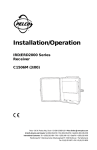
®
ON
0
0
-90
-35
00
TILT
+35 0
1800
+9
00
0
0
PAN
360 0
OFF
AZL–Azmith and Elevation
Read-Out Meter
Installation/Operation Manual
C521M (6/95)
Pelco • 300 W. Pontiac Way, Clovis, CA 93612-5699 • USA • (800) 289-9100 or (1-559) 292-1981
FAX (800) 289-9150 or (1-559) 292-3827 • DataFAX (800) 289-9108 or (1-559) 292-0435
International customers call (1-559) 292-1981 or FAX (1-559) 348-1120
TABLE OF CONTENTS
Section
Page
1.0
WARNINGS ........................................................................................................................................1
2.0
SCOPE ...............................................................................................................................................2
3.0
DESCRIPTION ................................................................................................................................... 2
4.0
INSTALLATION ................................................................................................................................... 2
4.1 CONNECTOR INSTALLATION ................................................................................................. 2
4.2 AZL METER ADJUSTMENT .................................................................................................... 4
4.2.1 Preliminary Remarks ................................................................................................... 4
4.2.2 Pan Meter Adjustment ................................................................................................. 5
4.2.3 Tilt Meter Adjustment ................................................................................................... 6
5.0
OPERATION ....................................................................................................................................... 6
6.0
SPECIFICATIONS .............................................................................................................................. 6
7.0
WARRANTY AND RETURN INFORMATION ..................................................................................... 7
®Pelco and the Pelco logo are registered trademarks of Pelco.
©Copyright 1995, Pelco. All rights reserved.
ii
Pelco Manual C521M (6/95)
LIST OF ILLUSTRATIONS
Figure
Page
1
Installation/Block Diagram ...............................................................................................................2
2
AZL Wiring Diagram ........................................................................................................................3
3
AZL Front and Rear Views .............................................................................................................. 4
4
AZL Wiring Interface to P/T .............................................................................................................4
5
Meter Adjustment ............................................................................................................................ 5
REVISION HISTORY
Manual #
C521M
Date
6/95
Pelco Manual C521M (6/95)
Comments
Original version.
iii
(This page intentionally left blank.)
iv
Pelco Manual C521M (6/95)
INSTALLATION/OPERATION MANUAL
AZL–AZMITH AND ELEVATION
READ-OUT METER
1.0 WARNINGS
Prior to installation and use of this product, the following
WARNINGS should be observed.
1.
2.
Installation and servicing should only be done by
Qualified Service Personnel and conform to all
Local codes.
Unless the unit is specifically marked as a NEMA
Type 3, 3R, 3S, 4, 4X, 6, or 6P enclosure, it is
designed for indoor use only and it must not be
installed where exposed to rain and moisture.
3.
Only use replacement parts recommended by Pelco.
4.
After replacement/repair of this unit’s electrical
components, conduct a resistance measurement
between line and exposed parts to verify the exposed
parts have not been connected to line circuitry.
Theproduct may bear the following marks:
This symbol indicates that dangerous voltage
constituting a risk of electric shock is present
within this unit.
This symbol indicates that there are important
operating and maintenance instructions in the
literature accompanying this unit.
CAUTION:
TO REDUCE THE RISK OF ELECTRICAL
SHOCK, DO NOT REMOVE COVER. NO
USER-SERVICEABLE PARTS INSIDE.
REFER SERVICING TO QUALIFIED
SERVICE PERSONNEL.
CAUTION:
RISK OF ELECTRIC SHOCK.
DO NOT OPEN.
Please thoroughly familiarize yourself with the information in this manual
prior to installation and operation.
Pelco Manual C521M (6/95)
1
2.0 SCOPE
4.1 CONNECTOR INSTALLATION
The information contained within this manual covers
the AZL (Azmith and Elevation Read-Out Meter).
Reference Figure 2 and Figure 3. Before connecting
the wiring, set the meter module “full scale” adjustment pots (these are the 5K pots) on the back of the
AZL unit at the full CW (clockwise) position and set
the “center scale” adjustment potentiometers (these are
the 1K pots) on the back of the AZL unit at approximately center.
3.0 DESCRIPTION
The AZL is used to provide a visual read-out (in degrees) of the mechanical position of DC based pan/tilts
such as Pelco's P/T1250DC/PP equipped with position
feedback pots.
The AZL consists of two easily read Simpson meters
mounted on the front panel of the unit along with the
power switch and power on indicator.
The fourteen pin CPC connector on the back panel of
the unit provides the necessary wiring interface for the
unit. This wiring interface is usually integrated with
controller wiring at the point where the cabling connection is made to the P/T (reference Figure 1's simplified diagram). The rest of the back panel consists of
installation set-up pots for initial meter calibration. A
power input cord, input line fuse and a convenient power
outlet plug round out the back-panel connections.
Now, reference the AZL wiring diagram in Figure 2.
The wiring for connector pins 2 and 9 go to the “pan
feedback” and “tilt feedback lines”, respectively, on the
P/T, which, in the case of a PT1250DC/PP, share corresponding numbered pinouts. For the rest of the AZL
wiring, we have pin 10 - which is AZL common - that
is wired to feedback common (pin 10) on the P/T and
pin 11 (AZL B+, +5VDC) that is wired to “feedback
B+” on the P/T. We assume, of course, that any other
additional wiring needed for the system in question has
already been done or is also being done at this time
(controller wiring, for example). Once the wiring interface is in place, the next thing to consider is AZL meter
adjustment.
4.0 INSTALLATION
Installation consists of installing the interconnecting
cable between the AZL and the P/T in use and initial
adjustment of the meters for operation.
P/T
AZL
CONTROLLER
Figure 1. Installation/Block Diagram
2
Pelco Manual C521M (6/95)
Figure 2. AZL Wiring Diagram
Pelco Manual C521M (6/95)
3
ON
00
0
0
-35
-90
+35 0
1800
+9
00
TILT
0
0
PAN
360 0
OFF
PAN
5K
POT
OUTPUT
1K
POT
LOCKING
NUT
TILT
5K
1K
POT
POT
AC
OUTLET
AC
INPUT
F1
POT
ADJ
SCREW
Figure 3. AZL Front and Rear Views
AZL
5K
+
–
11
PT1250DC/PP
11 FEEDBACK B+
9
9
2
2
10
10
TILT FEEDBACK
TILT
1K
PAN FEEDBACK
5K
+
PAN
–
1K
FEEDBACK
COMMON
Figure 4. AZL Wiring Interface to P/T
4.2 AZL METER ADJUSTMENT
4.2.1 Preliminary Remarks
Figure 3 is a diagram of the internal wiring (minus power
supplies, etc.) of that part of the AZL unit related to
meter adjustment. Shown there are the full and center
scale pots for pan and tilt on the AZL as they would be
wired to the respective position feedback pots on a Pelco
P/T1250DC/PP. Interconnections between the two units
4
are shown as circled numbers. As shipped, the pan/tilt
unit is mechanically configured to be resting at horizontal in the tilt position and at approximately 180° in
the pan position.
The meter adjustment procedure for both the pan and
tilt meters follows the same method. Assuming you have
already performed the connector and pot adjustments
indicated in Section 4.1, the step-by-step procedure for
meter adjustment is as follows:
Pelco Manual C521M (6/95)
4.2.2 Pan Meter Adjustment
In our example:
1.
Turn on the power switch. There should be a slight
noticeable change in the meter reading.
360° - 270°/ 2 = 90°/ 2 = 45°
2.
Activate the PAN LEFT switch and observe the
pan meter reading. The AZL pan meter readout
should approach “0” as the unit rotates. The unit
will stop at the extreme left position. Note the meter
reading. For our example, let's assume the reading
is 60° (see Fig. 5a).
3.
Note the meter reading and activate the PAN
RIGHT switch until the unit reaches the extreme
right position. Note the meter reading. For our example, lets assume the reading is 330° (see Fig.
5b).
4.
These two meter readings define the “deflection
range” of the meter (in our case 330° - 60° = 270°,
see Fig. 5c) and mirrors mechanical pan movement
of the P/T between its extremes. This “range” must
now be shifted (in our case, to the left) by adjusting the “center scale potentiometer” (PAN 1K pot,
see Fig. 3) on the AZL back-panel to obtain a balanced meter deflection at both ends. The simplest
method of calculating what the balanced meter
deflection should be at both ends is to subtract the
“deflection range” from the total meter range and
divide by 2.
In other words, the entire range should be shifted
to the left enough so that the difference between
the deflection range reading made at the PAN LEFT
operation and 0° and the difference between the
PAN RIGHT operation and 360° are equal and have
a value of 45°. In our example, then, we require
the PAN RIGHT meter reading to be (360°- 45°),
or 315°. The current meter reading is at 330°, so
you must now adjust the “center scale pot” (PAN
1K pot, see Fig. 3) until you obtain a meter reading of 315°. This shifts or “rotates” the entire deflection range for a balanced meter deflection at
both ends as indicated in Figure 5d.
5.
Now adjust the “full scale potentiometer” (PAN
5K Pot, see Fig. 3) on the back of the AZL unit to
obtain a reading of 360°.
6.
Finally, activate the PAN LEFT switch until the
unit reaches the extreme left position. Verify the
meter reading to be “0” degrees. Make minor adjustments as necessary.
PAN LEFT
Deflection Range = 270
0
(a)
0
60
0
360
0
0
(c)
0
360
0
0
315
15
(d)
0
0
15
330
0
0
PAN RIGHT
(b)
0
330
0
0
0
360
0
0
360
0
45
0
Center scale potentiometer adjustment for
shifting deflection range for balanced reading.
Figure 5. Meter Adjustment
Pelco Manual C521M (6/95)
5
4.2.3 Tilt Meter Adjustment
6.0 SPECIFICATIONS
Use the same methods for the tilt adjustment as those
just employed for the pan meter adjustment.
ELECTRICAL
Once the procedure is complete, the extreme electrical
rotation limits can be reset down from the factory maximum settings.
5.0 OPERATION
Input Voltage:
120 VAC, 50/60 Hz
Power Cord:
3-wire grounded #18 Awg
Fuse Protection: F1--3A
F2--2/10ASB
When power is applied to the unit the power LED on
the front panel lights.
Connectors:
The pan and tilt meters on the front of the AZL unit
will give a direct, visual, real-time readout, in degrees,
of the physical orientation of the pan/tilt to which it has
been electrically connected.
GENERAL
6
Construction
Cover:
14-pin AMP CPC connector
120 VAC convenience outlet
Steel, powder-coated, black
Chassis:
Metal sheet, galvanized
Panel
Front:
Rear:
Aluminum, black, white silk screen
Alodine aluminum plate
Dimensions:
3.0"H x 15.55"W x 10.19"D
(7.62 cm x 39.50 cm x 25.88 cm)
Weight:
12 lbs (5.4 kg)
Pelco Manual C521M (6/95)
NOTES
Pelco Manual C521M (6/95)
7
7.0 WARRANTY AND RETURN
INFORMATION
WARRANTY
Pelco will repair or replace, without charge, any
merchandise proved defective in material or
workmanship for a period of one (1) year after the date
of shipment. Exceptions to this warranty are as noted
below:
If a warranty repair is required, the Dealer must contact
Pelco at (800) 289-9100 or (559) 292-1981 to obtain a
Repair Authorization number (RA), and provide the
following information:
1.
2.
3.
Model and serial number
Date of shipment, P.O. number, Sales Order
number, or Pelco invoice number
Details of the defect or problem
•
Two (2) years on all standard motorized and fixed
focal length lenses.
If there is a dispute regarding the warranty of a product
which does not fall under the warranty conditions
stated above, please include a written explanation with
the product when returned.
•
Two (2) years on Legacy®, Intercept®, CM8500/
CM9500/CM9750 Matrix and DF8 Fixed Dome
products.
Ship freight prepaid to:
•
Two (2) years on WW5700 series window wiper
(excluding wiper blades).
•
Two (2) years on cameras.
•
Six (6) months on all pan and tilts, scanners or
preset lenses used in continuous motion
applications (e.g., preset scan, tour and auto scan
modes).
Pelco
300 West Pontiac Way
Clovis, CA 93612-5699
Method of return shipment shall be the same or equal
to the method by which the item was received by Pelco.
RETURNS
Pelco will warranty all replacement parts and repairs
for 90 days from the date of Pelco shipment. All goods
requiring warranty repair shall be sent freight prepaid
to Pelco, Clovis, California. Repairs made necessary
by reason of misuse, alteration, normal wear, or accident
are not covered under this warranty.
In order to expedite parts returned to the factory for
repair or credit, please call the factory at (800) 2899100 or (559) 292-1981 to obtain an authorization
number (CA number if returned for credit, and RA
number if returned for repair). Goods returned for
repair or credit should be clearly identified with the
assigned CA/RA number and freight should be prepaid.
All merchandise returned for credit may be subject to
a 20% restocking and refurbishing charge.
Ship freight prepaid to:
Pelco assumes no risk and shall be subject to no liability
for damages or loss resulting from the specific use or
application made of the Products. Pelco’s liability for
any claim, whether based on breach of contract,
negligence, infringement of any rights of any party or
product liability, relating to the Products shall not
exceed the price paid by the Dealer to Pelco for such
Products. In no event will Pelco be liable for any
special, incidental or consequential damages (including
loss of use, loss of profit and claims of third parties)
however caused, whether by the negligence of Pelco or
otherwise.
Pelco
300 West Pontiac Way
Clovis, CA 93612-5699
The above warranty provides the Dealer with specific
legal rights. The Dealer may also have additional
rights, which are subject to variation from state to state.
8
Pelco Manual C521M (6/95)