1
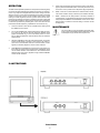
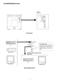
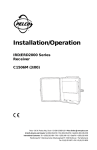
®
PMC09A Series
9" Color Monitor
Installation/Operation Manual
C989M (1/96)
PELCO • 300 W. Pontiac Way, Clovis, CA 93612-5699 • USA • (800) 289-9100 or (1-209) 292-1981
FAX (800) 289-9150 or (1-209) 292-3827 • DataFAX (800) 289-9108 or (1-209) 292-0435
IMPORTANT SAFEGUARDS
1.
Read Instructions - All the safety and operating instructions should
be read before the unit is operated.
2.
Retain Instructions - The safety and operating instructions should
be retained for future reference.
3.
Heed Warnings - All warnings on the unit and in the operating instructions should be adhered to.
4.
Follow Instructions - All operating and use instructions should be
followed.
5.
Cleaning - Unplug the unit from the outlet before cleaning. Do not
use liquid cleaners or aerosol cleaners. Use a damp cloth for cleaning.
6.
Attachments - Do not use attachments not recommended by the
product manufacturer as they may cause hazards.
7.
Water and Moisture - Do not use this unit near water - for example,
near a bath tub, wash bowl, kitchen sink, or laundry tub, in a wet
basement, near a swimming pool, in an unprotected outdoor installation, or any area which is classified as a wet location.
8.
Accessories - Do not place this unit on an unstable stand, tripod
bracket, or mount. The unit may fall, causing serious injury to a person and serious damage to the unit. Use only with a stand, tripod,
bracket, or mount recommended by the manufacturer, or sold with
the product. Any mounting of the unit should follow the manufacturer’s
instructions, and should use a mounting accessory recommended
by the manufacturer.
An appliance and cart combination should be moved with
care. Quick stops, excessive force, and uneven surfaces
may cause the appliance and cart combination to overturn.
9.
Ventilation - Openings in the enclosure, if any, are provided for ventilation and to ensure reliable operation of the unit and to protect it
from overheating. These openings must not be blocked or covered.
This unit should not be placed in a built-in installation unless proper
ventilation is provided or the manufacturer’s instructions have been
adhered to.
10. Power Sources - This unit should be operated only from the type of
power source indicated on the marking label. If you are not sure of
the type of power supply you plan to use, consult your appliance
dealer or local power company. For units intended to operate from
battery power, or other sources, refer to the operating instructions.
11. Grounding or Polarization - This unit may be equipped with a polarized alternating-current line plug (a plug having one blade wider
than the other). This plug will fit into the power outlet only one way.
This is a safety feature. If you are unable to insert the plug fully into
the outlet, try reversing the plug. If the plug should still fail to fit,
contact your electrician to replace your obsolete outlet. Do not defeat the safety purpose of the polarized plug.
14. Overloading - Do not overload outlets and extension cords as this
can result in a risk of fire or electric shock.
15. Object and Liquid Entry - Never push objects of any kind into this
unit through openings as they may touch dangerous voltage points
or short-out parts that could result in a fire or electric shock. Never
spill liquid of any kind on the unit.
16. Servicing - Do not attempt to service this unit yourself as opening or
removing covers may expose you to dangerous voltage or other
hazards. Refer all servicing to qualified service personnel.
17. Damage Requiring Service - Unplug the unit from the outlet and
refer servicing to qualified service personnel under the following
conditions:
a.
b.
c.
d.
e.
f
When the power-supply cord or plug is damaged.
If liquid has been spilled, or objects have fallen into the unit.
If the unit has been exposed to rain or water.
If the unit does not operate normally by following the
operating instructions. Adjust only those controls that are
covered by the operating instructions, as an improper
adjustment of other controls may result in damage and will
often require extensive work by a qualified technician to
restore the unit to its normal operation.
If the unit has been dropped or the cabinet has been
damaged.
When the unit exhibits a distinct change in performance—this
indicates a need for service.
18. Replacement Parts - When replacement parts are required, be sure
the service technician has used replacement parts specified by the
manufacturer or have the same characteristics as the original part.
Unauthorized substitutions may result in fire, electric shock or other
hazards.
19. Safety Check - Upon completion of any service or repairs to this
unit, ask the service technician to perform safety checks to determine that the unit is in proper operating condition.
20. Coax Grounding - If an outside cable system is connected to the
unit, be sure the cable system is grounded. U.S.A. models onlySection 810 of the National Electrical Code, ANSI/NFPA No.70-1981,
provides information with respect to proper grounding of the mount
and supporting structure, grounding of the coax to a discharge unit,
size of grounding conductors, location of discharge unit, connection
to grounding electrodes, and requirements for the grounding electrode.
21. Lightning - For added protection of this unit during a lightning storm,
or when it is left unattended and unused for long periods of time,
unplug it from the wall outlet and disconnect the cable system. This
will prevent damage to the unit due to lightning and power-line surges.
Alternately, this unit may be equipped with a 3-wire grounding type
plug, a plug having a third (grounding) pin. This plug will only fit into
a grounding-type power outlet. This is a safety feature. If you are
unable to insert the plug into the outlet, contact your electrician to
replace your obsolete outlet. Do not defeat the safety purpose of
the grounding-type plug.
12. Power-Cord Protection - Power-supply cords should be routed so
that they are not likely to be walked on or pinched by items placed
upon or against them, paying particular attention to cords and plugs,
convenience receptacles, and the point where they exit from the
appliance.
13. Power Lines - An outdoor system should not be located in the vicinity of overhead power lines or other electric light or power circuits, or
where it can fall into such power lines or circuits. When installing an
outdoor system, extreme care should be taken to keep from touching such power lines or circuits as contact with them might be fatal.
U.S.A. models only - refer to the National Electrical Code Article
820 regarding installation of CATV systems.
2
FCC & ICES INFORMATION
Safety Precautions
(U.S.A. and Canadian Models Only)
WARNING - This equipment has been tested and found to comply with
the limits for a Class B digital device, pursuant to Part 15 of the FCC
Rules and ICES-003 of Industry Canada. These limits are designed to
provide reasonable protection against harmful interference when the
equipment is operated in a residential installation. This equipment generates uses and can radiate radio frequency energy and, if not installed
and used in accordance with the instructions, may cause harmful interference to radio communications. However, there is no guarantee that
interference will not occur in a particular installation. If this equipment
does cause harmful interference to radio or television reception, which
can be determined by turning the equipment off and on, the user is encouraged to try to correct the interference by one or more of the following
measures:
-
Reorient or relocate the receiving antenna.
Increase the separation between the equipment and receiver.
Connect the equipment into an outlet on a circuit different from that
to which the receiver is connected.
Consult the dealer or an experienced radio/TV technician for help.
Intentional or unintentional changes or modifications not expressly approved by the party responsible for compliance shall not be made. Any
such changes or modifications could void the user’s authority to operate
the equipment.
The user may find the following booklet prepared by the Federal Communications Commission helpful: “How to Identify and Resolve Radio-TV Interference Problems”. This booklet is available from the U.S. Government
Printing Office, Washington, DC 20402, Stock No.004-000-00345-4.
CAUTION
RISK OF ELECTRIC SHOCK.
DO NOT OPEN!
CAUTION: TO REDUCE THE RISK OF ELECTRICAL SHOCK, DO NOT OPEN COVERS. NO USER
SERVICEABLE PARTS INSIDE. REFER SERVICING TO QUALIFIED SERVICE PERSONNEL.
This label may appear on the bottom of the unit due to space limitations.
The lightning flash with an arrowhead symbol, within an
equilateral triangle, is intended to alert the user to the
presence of uninsulated “dangerous voltage” within the
product’s enclosure that may be of sufficient magnitude
to constitute a risk of electric shock to persons.
The exclamation point within an equilateral triangle is intended to alert the user to presence of important operating and maintenance (servicing) instructions in the literature accompanying the appliance.
Warning
To prevent fire or shock hazard, do not expose units not specifically designed for outdoor use to rain or moisture.
Attention: Installation should be performed by qualified
service personnel only in accordance with the National
Electrical Code or applicable local codes.
Power Disconnect. Units with or without ON-OFF switches
have power supplied to the unit whenever the power cord
is inserted into the power source; however, the unit is
operational only when the ON-OFF switch is in the ON
position. The power cord is the main power disconnect
for all units.
Improper Operation. Alteration of the high voltage circuit
or changing the display tube type may result in an increase
in the x-ray emission of this unit. A unit altered in such a
way no longer meets the standards of certification and
must no longer be operated.
WARNING: Electrostatic-sensitive device. Use
proper CMOS/MOSFET handling precautions to
avoid electrostatic discharge.
NOTE: Grounded wrist straps must be worn and
proper ESD safety precautions observed when
handling the electrostatic-sensitive printed circuit boards.
3
CONTENTS
INSTALLATION
DESCRIPTION ............................................................... 4
INSTALLATION .............................................................. 4
OPERATION .................................................................. 5
MAINTENANCE ............................................................. 5
ILLUSTRATIONS ........................................................... 5
Location — The monitor should be located in a position such that the
flow of air around the unit is not restricted. Avoid heat vents or other heat
sources. Component life is greatly enhanced with moderate temperatures.
UNPACKING
Unpack carefully. This is electronic equipment and should be handled
with care.
Power
Model
No.1
PMC09A
PMC09A-X
The PMC09A Series are 23-cm (9-inch) color video monitors for specialized surveillance and industrial CCTV applications. These color monitors
provide excellent picture quality and convenient control of functions. They
are ideal for time lapse and event alarm VCR systems, or color video
multiplexers.
Voltage
Range
108 to 132
198 to 264
Nominal
Power 2
0.63 A
0.31 A
Color
System
NTSC
CCIR PAL
1.
These units may be supplied with grounded power cords; grounding should not be defeated.
2.
At rated voltage.
The shipping carton is the safest container in which the unit may be transported. Save it for possible future use.
DESCRIPTION
Rated
Voltage
120 VAC, 60 Hz
230 VAC.50Hz
Video Cabling — To assure good picture quality, use 75 ohm coaxial
cable and be sure the unit is terminated correctly. Cable attenuation should
also be considered on long cable runs and adequate video signal levels
provided.
When the monitor is located at the end of the cable run, use the VIDEO IN
connector on the rear of the chassis and set the termination switch to the
“75 Ω” position. Use the VIDEO OUT connector when the video cable is
“looped through” the monitor to other video equipment and set the termination switch on to the last piece of equipment on the line to the “75 Ω”
position.
4
OPERATION
To obtain the best possible operation from this product, the following setup
procedure should be followed when installing the monitor. The setup process is very simple and straightforward and involves nothing more than
attaching a source of color video and adjusting the controls to the detent
position. This provides a factory preset condition which allows normal
viewing. If contrast, brightness, chrome or phase need to be fine tuned,
please use the following procedures to obtain the best picture. Note that
the center detent position on all front panel controls is the normal setting;
a subcontrol is provided for presetting each control. The subcontrol adjustments should be adjusted by a qualified service technician only.
1.
Connect a camera or other source of standard color video signal to
the VIDEO IN of the monitor.
2.
Turn on the POWER switch; LED indicator will light. Allow the monitor to warm up for about 30 seconds. Adjust the PHASE control
(applies to PMC09A only), to the center detent position. If necessary, for best tint adjustment, rotate the Phase control to obtain the
desired picture.
3.
Adjust the CHROMA control to the center detent position. The monitor
screen should appear to provide a color image. If the image requires more color saturation rotate the control clockwise. If colors
appear too saturated, adjust the control counter-clockwise.
4.
Adjust BRIGHT and CONTRAST controls to the center detent position. If dark scene areas require enhancement, the BRIGHT control
can be rotated clockwise. If the “black level”, which determines the
darkest portion of the picture, appears too light, rotate the BRIGHT
control counter-clockwise.
5.
When video is looping through the monitor to another video device,
properly switch the termination switch on the rear panel of the monitor from the 75 ohm position to the HiZ position (High Impedance).
6.
NOTE - There are no external Vertical or Horizontal Hold controls .
The monitor contains circuitry to lock the synchronization internally.
7.
NOTE - Overdrive of the white portions of the video, sufficient to
cause blooming, can significantly shorten the service life of the CRT.
Always adjust the BRIGHT and CONTRAST controls to the center
detent position or towards a minimum setting to enhance monitor
life expectancy.
MAINTENANCE
ILLUSTRATIONS
Front Panels
5
This unit contains no user-serviceable components. Maintenance, beyond the adjustments described herein, should
be attempted only by trained technical personnel.
ILLUSTRATIONS (Cont’d)
Rear Panel
Typical Applications
6
WARRANTY AND RETURN
INFORMATION
WARRANTY
RETURNS
Pelco will repair or replace, without charge, any merchandise
proved defective in material or workmanship for a period of
one (1) year after the date of shipment. Exceptions to this
warranty are as noted below:
In order to expedite parts returned to the factory for repair or
credit, please call the factory at (800) 289-9100 or (209)
292-1981 to obtain an authorization number (CA number if
returned for credit, and RA number if returned for repair).
Goods returned for repair or credit should be clearly identified
with the assigned CA/RA number and freight should be
prepaid. All merchandise returned for credit may be subject to
a 20% restocking and refurbishing charge.
•
Six (6) months on all pan and tilts, scanners or preset
lenses used in continuous motion applications (e.g.,
preset scan, tour and auto scan modes).
•
Two (2) years on Legacy®, Intercept® and CM8500/
CM9500/CM9750 Matrix products.
•
Two (2) years on WW5700 series window wiper (excluding
wiper blades).
Ship freight prepaid to:
Pelco will warranty all replacement parts and repairs for 90
days from the date of shipment. All goods for warranty work
shall be sent freight prepaid to our Clovis, California facility.
Repairs made necessary by reason of misuse, alteration,
normal wear, or accident are not covered under this warranty.
Pelco is not liable for any incidental or consequential expenses
or liability incurred by the customer as a result of field repair,
installation, or any other reason.
The above warranty is in lieu of any other expressed or implied
warranty, condition, or guarantee by Pelco of the equipment
listed herein. Pelco makes no warranties except for intended
use and will not be liable for any loss, damage, or costs arising,
whether consequential or incidental, from the use of said
merchandise.
This warranty gives you specific legal rights. You may also
have additional rights, which are subject to variation from
state to state.
If a warranty repair is required, contact Pelco at (800) 2899100 or (209) 292-1981 for a Repair Authorization number
(RA), and provide the following information:
1.
2.
3.
Model and serial number
Date of shipment, P.O. number, Sales Order number,
or Pelco invoice number
Details of the defect or problem
If there is a dispute regarding the warranty of a product which
does not fall under the warranty conditions stated above,
please include a written explanation with the product when
returned.
Ship freight prepaid to:
Pelco
300 West Pontiac Way
Clovis, CA 93612-5699
Method of return shipment shall be the same as method by
which the repair item is received by Pelco.
7
Pelco
300 West Pontiac Way
Clovis, CA 93612-5699
®
Pelco
300 West Pontiac Way, Clovis, CA 93612-5699 (209) 292-1981 • (800) 289-9100
FAX (800) 289-9150 or (209) 292-3827 • DataFAX (800) 289-9108 or (209) 292-0435
International customers call 1-209-292-1981 or FAX 1-209-348-1120
(Product specifications subject to change without notice.)
C989M
8