1
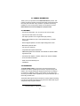
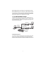
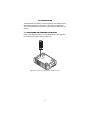
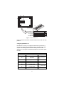
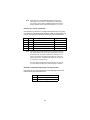
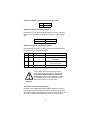
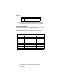
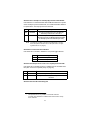
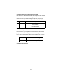
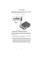
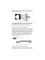
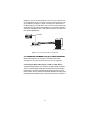
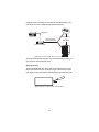
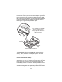
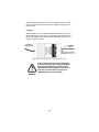
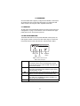
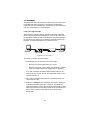
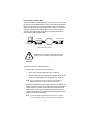
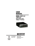
USER
MANUAL
MODEL 1082 and
1082/144
iDSL Modem with
V.34 or X.21 Interface
Part# 07M1082/C-B
Doc# 033151UB
Revised 2/19/03
CERTIFIED
An ISO-9001
Certified
Company
SALES OFFICE
(301) 975-1000
TECHNICAL SUPPORT
(301) 975-1007
TABLE OF CONTENTS
1.0
1.1
1.2
1.3
Warranty Information .................................................................
FCC Information ...........................................................................
CE Notice......................................................................................
Service..........................................................................................
4
4
4
5
2.0
2.1
2.2
2.3
General Information....................................................................
Features........................................................................................
Description....................................................................................
1082 SNMP Management Solutions.............................................
HTTP/HTML Management ...........................................................
6
6
6
7
7
3.0
3.1
Configuration .............................................................................. 8
Configuring the Hardware DIP Switches ...................................... 8
Configuring DIP Switch S1 ........................................................... 9
Switches S1-1 and S1-2: Data Rate........................................... 10
Switch S1-3: Data Set Ready during Line Loopback Test.......... 10
Switch S1-4: Must be set to the ON position (Reserved). .......... 11
Switch S1-5: Asynchronous/Sync Operation.............................. 11
Switches S1-6 and S1-7: System Clock Mode ........................... 11
Switch S1-8: Response to RDL Request.................................... 11
Configuring DIP switch S2.......................................................... 12
Switches S2-1: 19.2 kbps or 144 kbps Synchronous
Rate Enable................................................................................ 13
Switch S2-2: Front Panel Switch Disable ................................... 13
Switches S2-3: Response to Local Line Loop
Requests from DTE .................................................................... 13
Switches S2-4 and S2-5: Not Assigned...................................... 13
Switch S2-6: Response to RDL Request from DTE ................... 14
Switch S2-7: Compatability Mode............................................... 14
Switch S2-8: Not Assigned ......................................................... 14
4.0
4.1
4.2
Installation.................................................................................
Connecting the Twisted Pair Interface........................................
Connecting the Model 1082 (V.35) Serial Interface....................
Connecting the Model 1082 (V.35) to a DTE Device..................
Connecting the Model 1082 (V.35) to a DCE Device .................
Connecting the Model 1082 (X.21) Serial Interface....................
Connecting the Model 1082 (X.21) to a “DCE” or
“DTE” Device ..............................................................................
Opening the Case.......................................................................
Connecting Power ......................................................................
Universal AC Power (100–240VAC)...........................................
DC Power ...................................................................................
15
15
16
16
16
17
Operation...................................................................................
Power-up ....................................................................................
LED Status Monitors...................................................................
Test Modes .................................................................................
21
21
21
22
4.3
4.4
5.0
5.1
5.2
5.3
2
17
18
19
19
20
Local Line Loopback (LLB)......................................................... 22
Remote Digital Loopback (RDL)................................................. 23
Using the V.52 (BER) test pattern generator.............................. 24
A
A.1
A.2
A.3
A.4
A.5
A.6
A.7
A.8
A.9
A.10
A.11
A.12
A.13
A.14
A.15
Model 1082 Specifications ....................................................... 25
Transmission Format ................................................................... 25
Transmission Line ....................................................................... 25
Clocking ...................................................................................... 25
Distance ...................................................................................... 25
Data Rates .................................................................................. 25
Diagnostics ................................................................................. 25
LED Status Indicators ................................................................. 25
Connectors ................................................................................. 26
Power .......................................................................................... 26
Temperature Range .................................................................... 26
Altitude ........................................................................................ 26
Humidity ...................................................................................... 26
Dimensions ................................................................................. 26
Weight ......................................................................................... 26
Line Interface .............................................................................. 26
B
Model 1082C and 1082D Factory Replacement Parts and
Accessories............................................................................... 27
C
Model 1082C and 1082D Interface Pin Assignments............. 28
D
Model 1082C and 1082D Interface Pin Assignments............. 29
E
Model 1082C and 1082D Interface Pin Assignment............... 30
3
1.0 WARRANTY INFORMATION
Patton Electronics warrants all Model 1082 and Model 1082/144 components to be free from defects, and will—at our option—repair or
replace the product should it fail within one year from the first date of
shipment.
This warranty is limited to defects in workmanship or materials, and does
not cover customer damage, abuse or unauthorized modification. If this
product fails or does not perform as warranted, your sole recourse shall
be repair or replacement as described above. Under no condition shall
Patton Electronics be liable for any damages incurred by the use of this
product. These damages include, but are not limited to, the following: lost
profits, lost savings and incidental or consequential damages arising
from the use of or inability to use this product. Patton Electronics specifically disclaims all other warranties, expressed or implied, and the
installation or use of this product shall be deemed an acceptance of
these terms by the user.
1.1 FCC INFORMATION
This equipment has been tested and found to comply with the limits for a
Class A digital device, pursuant to Part 15 of the FCC Rules. These limits
are designed to provide reasonable protection against harmful interference when the equipment is operated in a commercial environment. This
equipment generates, uses, and can radiate radio frequency energy and,
if not installed and used in accordance with the instruction manual, may
cause harmful interference to radio communications. Operation of this
equipment in a residential area is likely to cause harmful interference in
which case the user will be required to correct the interference at his own
expense. If this equipment does cause harmful interference to radio or
television reception, which can be determined by turning the equipment
off and on, the user is encouraged to try to correct the interference by
one or more of the following measures:
• Reorient or relocate the receiving antenna
• Increase the separation between the equipment and receiver
• Connect the equipment into an outlet on a circuit different from that to
which the receiver is connected
1.2 CE NOTICE
The CE symbol on your Patton Electronics equipment indicates that it is in
compliance with the Electromagnetic Compatibility (EMC) directive and
the Low Voltage Directive (LVD) of the Union European (EU). A Certificate
of Compliance is available by contacting Patton Technical Support.
4
1.3 SERVICE
All warranty and non-warranty repairs must be returned freight prepaid
and insured to Patton Electronics. All returns must have a Return Materials Authorization number on the outside of the shipping container. This
number may be obtained from Patton Electronics Technical Service at:
Tel: (301) 975-1007
E-mail: [email protected]
URL: www.patton.com
Note
Packages received without an RMA number will not be
accepted.
Patton Electronics’ technical staff is also available to answer any questions that might arise concerning the installation or use of your
Model 1082 or Model 1082/144. Technical Service hours: 8AM to 5PM
EST, Monday through Friday.
5
2.0 GENERAL INFORMATION
Thank you for your purchase of this Patton Electronics product. This
product has been thoroughly inspected and tested and is warranted for
One Year parts and labor. If any questions or problems arise during
installation or use of this product, please do not hesitate to contact
Patton Electronics Technical Support at (301) 975-1007.
2.1 FEATURES
• Synchronous data rates: 19.2, 32, 56, 64, 128, and 144* kbps
• Asynchronous data rates: 0–38.4 kbps
• Full duplex operation over a single twisted pair (2-wires)
• Point-to-point distances up to 5 miles (all data rates) on 24 AWG
twisted pair
• Remote digital loopback, local line loopback diagnostic modes
• Multi-Rate Symmetric DSL
• V.35 and X.21 Interfaces
• Compatible with Popular Model 1092
• SNMP Manageable with 1092ARC and 1001MC as 1001MC SNMP
Agent Rack Card
• Universal Power Options, 120VAC, 230VAC and -48VDC Available
• Front Panel Status Indicators
• Small, Convienent Desktop Unit
• CE Marked
2.2 DESCRIPTION
The Patton Model 1082 is a high speed, AC powered short range
modem that is able to operate synchronously or asynchronously—full
duplex—over a single twisted pair. Supporting data rates to 128 kbps—
or 144 kbps on 1082/144 models—(synchronous) or 38.4 kbps (asynchronous), the Model 1082 is capable of point-to-point distances up to 5
miles using 24 AWG wire.
The Model 1082 supports internal, external or receive loopback clocking
in synchronous mode. Data rates and asynchronous data format may be
configured locally using DIP switches.
*
144 kbps available on 1082/144 models only.
6
Model 1082/C provides a V.35 interface on an M/34 female connector.
Model 1082/D provides an X.21 interface on a DB-15 female connector.
Line connection is made by an RJ-45 jack. Standard versions of Model
1082 are powered by a 100-240VAC (Universal) supply. The DC power
supply option supports any DC input between 36–72VDC.
2.3 1082 SNMP MANAGEMENT SOLUTIONS
The Model 1082 and Model 1082/144 are SNMP manageable when connected to a rack-mounted Model 1092ARC (see Figure 1). SNMP management is enabled through a 1001MC rack management card located in the
Patton Electronics Rack System.
Model 1082
10Base-T
connection
to 1001MC
2B1Q
connections to
remote 1082s
Management
Station
Model 1082
Rack-mounted
1092ARCs
Figure 1. Typical application
HTTP/HTML Management
The 1001MC maintains HTML pages that can be viewed through a Web
browser. You can display remote statistics and configure Model 1082
parameters simply by entering the 1001MC’s IP address into the browser.
7
3.0 CONFIGURATION
The Model 1082 and 1082/144 each are equipped with 16 DIP switches
that enable configuration of the unit for a wide variety of applications.
This section describes switch locations and explains the different configurations
3.1 CONFIGURING THE HARDWARE DIP SWITCHES
Using a small flat-tip screwdriver, remove the protective cover located on
the underside of the Model 1092 (see Figure 2).
DS
Mo
/G
l1
03
G.7s NS
tu
Link
Sta
BT
L 10
de
19
4E
Sin
gle
od
tM
es M
4T T
.70 ER
Mo
de
51
1E
es
Fib
5
D
N
1/R
51
em
od
4L M
.7S0
/GiD
a0s3tT
0B.7
BL
d1G
/R
uak
1E
Qin
- tL
51 al
eNr e
11 orm L
Figure 2. Removing the cover to access DIP switches S1 and S2
8
S1
S2
S2
ON
ON
1 2 3 4 5 6 7 8
1 2 3 4 5 6 7 8
S1
N
1
2
3
4
O
Switch toggle
5
6
7
8
S1
Push toggle up ON
for ON position
1 2 3 4 5 6 7 8
1 2
S1
Push toggle
down for
OFF position
ON
Figure 3. DIP switches S2 and S2
Figure 3 shows the orientation of the DIP switches in the “ON” and “OFF”
positions.
Configuring DIP Switch S1
DIP switch S1 is where you configure the data rate, asynchronous or
synchronous data format, transmit clock source, and response to RDL
request. The following table summarizes default positions of DIP
switches S1-1 through S1-8. Detailed descriptions of each switch follow
the table.
Position
S1 Summary Table
Function
S1-1
Data Rate
On
S1-2
Data Rate
Off
S1-3
Factory Default
}
DSR during Local Line Loop On
S1-4
Reserved
On
S1-5
Async/Sync Data Format
Off
S1-6
Tx Clock Source
On
S1-7
Tx Clock Source
On
S1-8
Response to RDL Request
On
9
64K Sync
DSR On
}
Internal Clock
Enable
Note
When setting the 1082 for SNMP Management, the DTE rate
switches (S1-1,S1-2, and S2-1) must be also set to the ON position. Therefore, to set a 1082 unit SNMP Mangagement mode, the
following switches have to be at the ON position, S1-1, S1-2, S2-1.
Switches S1-1 and S1-2: Data Rate
Use switches S1-1 and S1-2 to configure the asynchronous or synchronous data rate of the Model 1082 and Model 1082/144. Each setting represents one synchronous data rate and one asynchronous data rate.
S1-1
S1-2
Sync Data Rate
Async. Data Rate
On
Off
On
Off
Off
On
On
Off
Off
Off
32 kbps
56 kbps
64 kbps
128 kbps (see note)
144 kbps or 19.2 kbps (see note)
Reserved
Reserved
Reserved
0–38.4 kbps
Reserved
Note
The Model 1082 can also operate at the 19.2 kbps synchronous
rate, and the Model 1092/144 can also operate at the 144 kbps
synchronous rate. To operate at these rates, set switches S1-1
and S1-2 both to the OFF position and Switch S2-1 to the ON
position (see section , “Configuring DIP switch S2” on page 122
for a description of Switch S2-1).
If the S2-1 switch is positioned in the OFF position, the 128 kbps
sync data rate/0–38.4 kbps async data rate option is selected.
Switch S1-3: Data Set Ready during Line Loopback Test
Use Switch S1-3 to control the behavior of the DSR signal at the EIA
interface during the line loopback test.
S1-3
Setting
On
Off
DSR is on during local line loop
DSR is off during local line loop
10
Switch S1-4: Must be set to the ON position (Reserved).
S1-4
Setting
On
Reserved
Switch S1-5: Asynchronous/Sync Operation
Use switch S1-5 to configure the Model 1082 for async/sync operation.
Switch S1-5 must be set in the Off position. There is no other valid setting.
S1-5
Setting
Off
Async/Sync
Switches S1-6 and S1-7: System Clock Mode
Use Switches S1-6 and S1-7 to configure the 1082 or Model 1082/144
for internal, or receive recover clock mode.
S1-6
S1-7
Clock Mode
Description
On
Off
On
On
Internal
External (DTE)
On
Off
Receive Recover
System clock generated internally
System clock derived from terminal interface
System clock derived from the
received line signal
Off
Off
Hardware Reset
A pair of Model 1082s communicate synchronously
across the twisted pair line connection. Therefore, you
must set these switches whether your application is
async or sync. For X.21 or Async applications, configure
one Model 1082 for internal clock mode and the other
Model 1082 for receive recover clock mode.
Important
Switch S1-8: Response to RDL Request
Use Switch S1-8 to allow Model 1082 and Model 1082/144 to enter the
Remote Digital Loopback diagnostic test when requested to do so by the
far end Model 1082 or Model 1082/144. For example, when switch S1-8 is
set to “ON”, it will enter RDL mode (See section 5.3, “Test Modes” on
11
page 22) when requested to do so by the remote Model 1082 and Model
1082/144.
Note
S1-8
Setting
On
Off
Response to RDL Request Enabled
Response to RDL Request Disabled
The Remote Digital Loopback (RDL) will not work for 144 kbps.
You must first set the units to 128 kbps or slower to use the RDL.
Configuring DIP switch S2
Use the eight DIP switches in S2 to enable 19.2 kbps or 144* kbps synchronous operation and set the loopback modes. The following table
summarizes default positions of DIP switches S2-1 through S2-8.
Detailed descriptions of each switch follow the table.
*
Position
S2 Summary Table
Function
S2-1
19.2 or 14 4* kbps Enable
Off
S2-2
Front Panel Switch Disable
Off
S2-3
Response to LAL from DTE
Off
S2-4
Not Assigned
Off
S2-5
Not Assigned
Off
S2-6
Response to RDL from DTE
On
S2-7
Compatibility Mode
Off
S2-8
Not Assigned
Off
Factory Default
Disabled
Enabled
144 kbps data rate is only available on the Model 1082/144.
19.2 kbps rate is available on all Model 1082 series modems except
for the 1082/144.
12
Switches S2-1: 19.2 kbps or 144* kbps Synchronous Rate Enable
Use switch S2-1 to allow the Model 1082 and Model 1082/144 to operate
at the 19.2 kbps synchronous data rate, or to enable the Model 1082/144
to operate at the 144* kbps synchronous data rate.
S2-1
Activation
Description
Off
Disabled
On
Enabled
Synchronous data rate is 32–128 kbps as
defined by switches S1-1 and S1-2
Model 1082 operates at synchronous 19.2 kbps
data rate (see note). The Model 1082/144 operates
at 144 kbps synchronous data rate (see note)
Note
To operate at 19.2 kbps or 144 kbps, set switches S1-1 and S1-2
to the OFF position and switch S2-1 to ON (see section “Configuring DIP Switch S1” on page 9).
Switch S2-2: Front Panel Switch Disable
Use switch S2-2 to enable or disable the front panel toggle switches.
S2-2
Setting
On
Off
Disable the front panel switches
Enable the front panel switches
Switches S2-3: Response to Local Line Loop Requests from DTE
Use switch S2-3 to enable Local Line Loopback from the local DTE interface (See “Local Line Loopback (LLB)” on page 22).
S2-3
Activation
Description
Off
ON
Disabled
Enabled
Ignore Line Loop Back request from DTE interface
Respond to Line Loop Back request from DTE
interface
Switches S2-4 and S2-5: Not Assigned
*
144 kbps data rate is only available on the Model 1082/144.
19.2 kbps rate is available on all Model 1082 series modems except
for the 1082/144.
13
Switch S2-6: Response to RDL Request from DTE
Use switch S2-6 to determine the Model 1082 response to RDL requests
from the local DTE. In the enabled setting, the 1082 responds to RDL
requests from the local DTE by sending an RDL loop request to the
remote Model 1082 (See “Remote Digital Loopback (RDL)” on page 23).
S2-3
Activation
Description
Off
Disabled
On
Enabled
Ignore Remote Digital Loopback request from
DTE interface
Respond to Remote Digital Loopback request
from DTE interface
Switch S2-7: Compatability Mode
In some instances, you may need to connect a Model 1082 to a third
party IDSL modem. By enabling S2-7 the 1082 will negotiate and link up
to a non-Patton IDSL Modem. When using two Patton units, set 2-7 to
the default position.
S2-7
Activation
Setting
Off
On
Disabled
Enabled
Default position
Compatibility Mode
Switch S2-8: Not Assigned
14
4.0 INSTALLATION
Once the Model 1082 has been configured, it is ready to connect to the
twisted pair interface, to the serial port, and to the power source. This
section tells you how to make these connections.
V.35 connector
ON
Made in the USA
|
Power
OFF O
Line interface
Interface
Line
Power input
connector
Mo
G.7
Po de
wel 11
r 9
03
/G
4E
Sin
gle
.70
5M1
4T
es
a1dE
e in
tM
Mo
de
od
es
DSFib
L er -
the
US
A
Qu
ad
G.7
03
/G.7
04
M
Linode
e m
Figure 4. Model 1082 or Model 1082/144 rear view
4.1 CONNECTING THE TWISTED PAIR INTERFACE
The Model 1082 supports communication between two DTE devices at
distances to 5 miles (8 km) over 24 AWG (.5mm) twisted pair wire. Two
things are essential:
1. These units work in pairs. Both units at the end of the twisted pair
DSL span must be set for the same DTE rate.
2. To function properly, the Model 1082 needs one twisted pair of
metallic wire. This twisted pair must be unconditioned, dry, metallic
wire, between 19 (.9mm) and 26 AWG (.4mm) (the higher number
gauges will limit distance). Standard dial-up telephone circuits, or
leased circuits that run through signal equalization equipment, or
standard, flat modular telephone type cable, are not acceptable.
15
The RJ-45 connector on the Model 1082’s twisted pair interface is polarity insensitive and is wired for a two-wire interface. The signal/pin relationships are shown in Figure 5.
Figure 5. Model 1082 RJ-45 twisted pair line interface
4.2 CONNECTING THE MODEL 1082 (V.35) SERIAL INTERFACE
Model 1082 supports V.35 serial port connections. This section
describes how to connect the serial ports to your V.35 equipment.
Connecting the Model 1082 (V.35) to a DTE Device
The Model 1082 provides a V.35 DCE (Data Circuit Terminating Equipment) interface on an M/34 female connector. As a DCE, this interface is
designed to connect to DTE equipment, such as a router. When connecting the V.35 interface of the Model 1082 to your DTE device, use a V.35
straight-through cable (see Figure 6). Appendix C, “Model 1082C and
1082D Interface Pin Assignments” on page 28 describes pin assignments and signal sources for the Model 1082 V.35 interface. When purchasing or constructing an interface cable, please refer to the pin
diagrams in Appendix C as a guide.
DSL Span
Model 1082
Straight-through M/34 cable
Model 1082 (DCE)
V.35 Router (DTE)
Figure 6. Connecting the Model 1082 to a V.35 serial DTE
Connecting the Model 1082 (V.35) to a DCE Device
The Model 1082 provides a V.35 DCE (Data Circuit Terminating Equipment) interface on an M/34 female connector. As a DCE, this interface is
16
designed to connect to DTE equipment, such as a router. However, tailcircuit applications require connection to another DCE equipment, such
as a multiplexer (see Figure 7). When connecting the V.35 interface of
the Model 1082 to your DCE device, use a V.35 null modem cable. Some
applications may also require the installation of a V.35 tail-circuit buffer to
account for small differences in clock frequency between the 1082 and
the V.35 DCE (Multiplexer).
DSL Span
Model 1082
Model 1082 (DCE)
V.35 Multiplexer (DCE)
Figure 7. Connecting the Model 1082 to V.35 serial DCE
4.3 CONNECTING THE MODEL 1082 (X.21) SERIAL INTERFACE
Model 1082 supports X.21 serial port connections. This section
describes how to connect the serial ports to your X.21 equipment.
Connecting the Model 1082 (X.21) to a “DCE” or “DTE” Device
The Model 1082 provides an X.21 interface on a DB-15 female connector.
The X.21 interface default configuration is DCE (Data Circuit Terminating
Equipment) for connection to DTE (Data Terminal Equipment) such as a
router. However, the X.21 interface on the Model 1082 may be configured as
DTE (Data Terminal Equipment) for connection to DCE such as a modem or
17
multiplexer. When connecting the X.21 interface of the Model 1082 to your
DTE device, use a X.21 straight through cable (see Figure 8).
DSL Span
Model 1082
Straight-through
15-pin D-Sub cable
Router (DTE)
or
Mux (DCE)
Model 1082 (DCE)
Figure 8. Connecting the Model 1082 to X.21 DTE or DCE
To change the DCE/DTE orientation from the default position (DCE), you
must open the case Model 1082 case.
Opening the Case
To open the Model 1082 case, insert a flat head screw driver into an open
slot on both sides of the case, as shown in Figure 9. Twist the screw driver
head slightly and the top half of the case will separate from rest of the case.
Figure 9. Opening the 1082 case with a small screwdriver
18
The DCE/DTE strap is located on the top side of the 1082 PC board (see
Figure 10). The arrows on the top of the strap indicate the configuration
of the X.21 port (for example, if the DTE arrows are pointing toward the
DB-15 connector, the X.21 port is wired as a DTE). Change the DCE/
DTE orientation by pulling the strap out of its socket, rotating it 180º, then
plugging the strap back into the socket. To close the case, fit the two
halves together snugly and snap them back in place.
l
G.
In this example, the DCE/DTE
strap is configured for DTE
because the DTE label on the
strap is pointed toward the
DB-15 connector
70
er 119
4E
3/G
.70
Sin
gle
5M1
4T
es
a1dE
ei
tM
Mo
d
nt
od
es
he
e
Int Fib
er er
fac - Q
e ua
US
A
dG
.70
3/G
.70
4M
Linode
e m
DB-15 (X.21)
connector
Mo
G.7
Po de
wel 11
r 9
03
/G
4E
Sin
gle
.70
5M1
4T
es
Mo
a1dE
e in
tM
od
es
de
Inte
F
rfaiber
ce - Q
the
US
A
ua
dG
DCE/DTE
strap
.70
3/G
.70
4M
Linode
e m
Figure 10. Setting the DCE/DTE strap
4.4 CONNECTING POWER
The Model 1082 (all versions) are available with Universal AC (100–
240VAC), 120VAC, 230VAC or -48VDC power options. This section
describes these options.
Universal AC Power (100–240VAC)
The Model 1082 uses a 5VDC, 2A universal input 100-240VAC, power
supply (center pin is +5V). The universal input power supply has a male
IEC-320 power entry connector. This power supply connects to the
Model 1082 by means of a barrel jack on the rear panel. Many international power cords are available for the universal power supply (Refer to
Appendix B, “Model 1082C and 1082D Factory Replacement Parts and
Accessories” on page 27 for country-specific power cords.
19
The Model 1082 powers up as soon as it is plugged into an AC outlet-there is no power switch.The Universal AC supply is equipped with a
male IEC-320
DC Power
The 36-60 VDC DC to DC adapter supplied with the DC version of the
Model 1082 plugs in a DC source (nominal 48VDC) and plugs into the
barrel power supply jack on the rear of the 1082. Refer to Figure 11 to
make the proper connection.
To Power
Supply Jack
-Vin
To -48VDC
Source
+Vin
Figure 11. Connecting DC power to the 48V-PSM DC power supply
z
There are no user-serviceable parts in the power supply
section of the Model 1082. Fuse replacement should only
be performed by qualified service personnel. Contact
Patton Electronics Technical support at +1 (301) 975-1007,
via our web site at www.patton.com, or by E-mail at
[email protected], for more information.
WARNING
20
5.0 OPERATION
Once the Model 1082 is properly configured and installed, it should operate transparently. This sections describes power-up, reading the LED
status monitors, and using the built-in loopback test modes.
5.1 POWER-UP
To apply power to the Model 1082, first be sure that you have read “Connecting Power” on page 19, and that the unit is connected to the appropriate power source. Then power-up the unit.
5.2 LED STATUS MONITORS
The Model 1082 features six front panel LEDs that monitor power, the
DTE signals, network connection and test modes. Figure 12 shows the
front panel location of each LED. See also, LED description Table 1.
NetLink™ 10Base-T iDSL Model
Link
DSL
10BT
DSL
NS
ER
NS
10BT
ER
TM
511E/RDL
Normal
511/RDL
TM Loopback
switch
Figure 12. Model 1082 front panel
Table 1: LED descriptions
DSL Link
TD & RD
NS
ER
TM
(Active Green) Solid green (On) indicates that the end
to end DSL Framer Link is up, signifying that the link
across the DSL span is active. The DSL Link LED is Off
when the link is down.
Glows yellow to indicate an idle condition of Binary “1”
data on the respective terminal interface signals. Green
indicates Binary “0” data
(No Signal) glows red to indicate that the local Model
1082 is not connected with the remote Model 1082.
Blinks ON/OFF after a 511/511E test has timed out.
See “Using the V.52 (BER) test pattern generator” on
page 24 for more information.
Glows yellow to indicate TM
21
5.3 TEST MODES
The Model 1082 offers two proprietary loopback test modes, plus a builtin V.52 BER test pattern generator, to evaluate the condition of the
modems and the communication link. These tests can be activated physically from the front panel, or via the interface.
Local Line Loopback (LLB)
The Local Line Loopback (LLB) test checks the operation of the local
Model 1082, and is performed separately on each unit. Any data sent to
the local Model 1082 in this test mode will be echoed (returned) back to
the user device (see Figure 13). For example, characters typed on the
keyboard of a terminal will appear on the terminal screen.
LLB initiated
Figure 13. Local Line Loopback
To perform an LLB test, follow these steps:
1. Activate LLB. This may be done in one of three ways:
—
Move the front panel toggle switch up to “Local”.
—
Raise the LLB signal on the interface (see Appendix C, “Model
1082C and 1082D Interface Pin Assignments” on page 28).
Once LLB is activated, the Model 1082 transmitter output is connected to its own receiver. Data is also looped back to the line. The
TM LED should be lit.
2. Verify that the data terminal equipment is operating properly and
can be used for a test.
3. Perform a V.52 BER (bit error rate) test as described in “Using the
V.52 (BER) test pattern generator” on page 24. If the BER test
equipment indicates no faults, but the data terminal indicates a fault,
follow the manufacturer’s checkout procedures for the data terminal.
Also, check the interface cable between the terminal and the
Model 1082.
22
Remote Digital Loopback (RDL)
The Remote Digital Loopback (RDL) test checks the performance of both
the local and remote Model 1082s, and the communication link between
them. Any characters sent to the remote Model 1082 in this test mode
will be returned back to the originating device (see Figure 14, below). For
example, characters typed on the keyboard of the local terminal will
appear on the local terminal screen after having been passed to the
remote Model 1082 and looped back.
Local 1082
Remote 1082
RDL initiated
Figure 14. Remote Digital Loop
Do not send a 511 test pattern from the test equipment
when you connect external test equipment to the 1082.
Important
To perform an RDL test, follow these steps:
1. Activate RDL. This may be done in three ways:
—
Move the front panel toggle switch down to Remote.
—
Raise the RDL signal on the interface (see Appendix C, “Model
1082C and 1082D Interface Pin Assignments” on page 28).
Note
Remote loopback cannot be activated until approximately 45
seconds after the two modems have linked to each other.
2. Perform a V.52 BER test as described in “Using the V.52 (BER) test
pattern generator” on page 24. If the BER test equipment indicates
a fault, and the Local Line Loopback test was successful for both
Model 1082s, you may have a problem with the twisted pair line
between the modems. You should then check the twisted pair line for
proper connections and continuity.
Note
The Remote Digital Loopback (RDL) will not work for 144 kbps.
You must first set the units to 128 kbps or slower to use the RDL.
23
Using the V.52 (BER) test pattern generator
To use the V.52 BER tests in conjunction with the Remote Digital Loopback tests (or with Local Line Loopback tests), do the following:
1. Locate the 511/511E toggle switch on the front panel of the
Model 1082 and set the toggle to the down position. This activates
the V.52 BER test mode and transmits a 511 test pattern into the
loop. If any errors are present, the local modem’s red ER LED will
blink continuously.
2. If the above test indicates that no errors are present, move the V.52
toggle switch to the up position, activating the 511/E test with errors
present. If the test is working properly, the local modem’s red ER
LED will blink. A successful 511/E test will confirm that the link is in
place, and that the Model 1082’s built-in 511 generator and detector
are working properly.
24
APPENDIX A
MODEL 1082 SPECIFICATIONS
A.1 TRANSMISSION FORMAT
Synchronous or asynchronous
A.2 TRANSMISSION LINE
Single unconditioned twisted pair
A.3 CLOCKING
Internal, external or receive loopback
A.4 DISTANCE
Distance, max, all data rates:
• 10.1 miles (16.4km) on 19 AWG (0.9mm) wire
• 7.2 miles (11.5 km) on 22 AWG (0.64mm) wire
• 5.0 (8 km) on 24 AWG (0.5mm) wire
• 3.4 (5.5 km) on 26 AWG (0.4mm) wire
A.5 DATA RATES
• Synchronous 19.2, 32, 56, 64,128, and 144* kbps
• Asynchronous 0–38.4 kbps
A.6 DIAGNOSTICS
V.52 compliant bit error rate pattern (511/511E pattern) generator and
detector with error injection mode; Local Line Loopback and Remote
Digital Loopback, activated by front panel switch or via serial interface
A.7 LED STATUS INDICATORS
TD, RD, DSL Link, NS (no signal), ER (error) and TM (test mode)
*
144 kbps data rate is only available on the Model 1082/144.
19.2 kbps rate is available on all Model 1082 series modems except
for the 1082/144.
25
A.8 CONNECTORS
RJ-45 on line side; DB-25 female, M/34 female or DB-15 female on serial
interface side.
A.9 POWER
100–253 VAC, 50–60 Hz (universal input option); 48 VDC (option).
5 watts.
A.10 TEMPERATURE RANGE
32–122°F (0–50°C)
A.11 ALTITUDE
0–15,000 feet (0–4,572 meters)
A.12 HUMIDITY
5 to 95%, non-condensing
A.13 DIMENSIONS
4.125W x 1.625H x 6.0D in. (10.5W x 4.1W x 15.2D cm)
A.14 WEIGHT
2.01 lbs. (1.0kg)
A.15 LINE INTERFACE
Transformer coupled 1500 VAC isolation
26
APPENDIX B
MODEL 1082C AND 1082D FACTORY REPLACEMENT PARTS AND
ACCESSORIES
Model #
Description
1082/C
1082/D
1082/144/C
1082/144/D
V.35 iDSL Modem
X.21 iDSL Modem
V.35 iDSL Modem with maximum data rate of 144 kbps
X.21 iDSL Modem with maximum data rate of 144 kbps
48V-PSM
08055DCUI
DC Power Supply Module
100-240VAC (+5V ±5% reg. DC/2A) Universal Input Adapter
0805EUR
0805UK
0805US
0805AUS
0805DEN
0805FR
0805IN
0805IS
0805JAP
0805SW
European Power Cord CEE 7 (“A”)
United Kingdom Power Cord (“D”)
American Power Cord (“K”)
Australia/New Zealand Power Cord (“C”)
Denmark Power Cord (“E”)
France/Belgium Power Cord (“F”)
India Power Cord (“G”)
Israel Power Cord (“H”)
Japan Power Cord (“J”)
Switzerland Power Cord (“L”)
07M1082
User Manual
27
APPENDIX C
MODEL 1082C AND 1082D INTERFACE PIN ASSIGNMENTS
V.35 INTERFACE
(M/34 Female Connector)
(DCE Orientation)
Pin #
Signal
B
C
D
E
F
H
L
M
N
P
R
S
T
U
V
W
X
Y
AA
SGND (Signal Ground)
RTS (Request to Send) (DTE Source)
CTS (Clear to Send) (DCE Source)
DSR (Data Set Ready) (DCE Source)
CD (Carrier Detect) (DCE Source)
DTR (Data Terminal Ready) (DTE Source)
LLB (Local Line Loop) (DTE Source)
TM (Test Mode) (DTE Source)
RDL (Remote Digital Loop) (DTE Source)
TD (Transmit Data) (DTE Source)
RD (Receive Data) (DCE Source)
TD/ (Transmit Data-B) (DTE Source)
RD/ (Receive Data-B) (DCE Source)
XTC (External Transmit Clock) (DTE
RC(Receiver Clock) (DCE Source)
XTC/ (External Transmit Clock) (DTE source)
RC/ (Receiver Clock) (DCE Source)
TC (Transmitter Clock-A) (DCE Source)
TC/ (Transmit Clock-B) (DCE Source)
28
APPENDIX D
MODEL 1082C AND 1082D INTERFACE PIN ASSIGNMENTS
X.21 Interface
(D-Sub-15 Female Connector)
(DTE /DCE Orientation)
Pin #
Signal
1
2
3
4
5
6
7
8
9
10
11
12
13
14
Frame Ground
T (Transmit Data-A) (DTE Source)
C (Control-A) (DTE Source)
R (Receive Data-A) (DCE Source)
I (Indication-A) (DCE Source)
S (Signal Element Timing-A) (DCE Source)
BT (Byte Timing-A) (DCE Source)
SGND (Signal Ground)
T/ (Transmit Data-B) (DTE Source)
C/ (Control-B) (DTE Source)
R/ (Receive Data-B) (DCE Source)
I/ (Indication-B) (DCE Source)
S/ (Signal Element Timing-B) (DCE Source)
BT/ (Byte Timing-B) (DCE Source)
29
APPENDIX E
MODEL 1082C AND 1082D INTERFACE PIN ASSIGNMENT
X.21 Interface
(DB-15 Female Connector)
(DTE /DCE Configuration)
Pin #
Signal
1
2
3
4
5
6
7
8
9
10
11
12.
13
14
Frame Ground
T (Transmit Data-A)
C (Control-A)
R (Receive Data-A)
I (Indication-A)
S (Signal Element Timing-A)
BT (Byte Timing-A)
SGND (Signal Ground)
T/ (Transmit Data-B)
C/ (Control-B)
R/ (Receive Data-B)
I/ (Indication-B)
S/ (Signal Element Timing-B)
BT/ (Byte Timing-B)
30
Notes
_________________________________________________________
_________________________________________________________
_________________________________________________________
_________________________________________________________
_________________________________________________________
_________________________________________________________
_________________________________________________________
_________________________________________________________
_________________________________________________________
_________________________________________________________
_________________________________________________________
_________________________________________________________
_________________________________________________________
_________________________________________________________
_________________________________________________________
_________________________________________________________
_________________________________________________________
_________________________________________________________
_________________________________________________________
_________________________________________________________
_________________________________________________________
31
Notes
_________________________________________________________
_________________________________________________________
_________________________________________________________
_________________________________________________________
_________________________________________________________
_________________________________________________________
_________________________________________________________
_________________________________________________________
_________________________________________________________
_________________________________________________________
_________________________________________________________
_________________________________________________________
_________________________________________________________
_________________________________________________________
_________________________________________________________
_________________________________________________________
_________________________________________________________
_________________________________________________________
_________________________________________________________
_________________________________________________________
_________________________________________________________
Copyright © 2000, 2001
Patton Electronics Company
All Rights Reserved
32