1
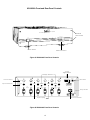
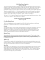
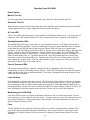
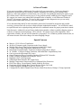
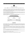
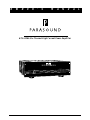
O
W
N
E
R
'
S
M
A
N
U
HCA-80 6A Si x Channel High Current Power Ampl if ier
i Amplifier
HCA-806A High Current Mult
Current Overload
Power
1
-1-
2
3
4
5
6
AC Line
Standby
Normal
A
L
Table of Contents
Important Safety Instructions ........................................................................................ 3
Figure #1 and #2 HCA-806A Front and Rear Panel Drawings ..................................... 4
Introduction ..................................................................................................................... 5
Installing and Rack Mounting Your Amplifier ................................................................ 5
Ventilation Requirements for Your Amplifier ................................................................. 5
Input Connections and Switch Settings for the HCA-806A ......................................... 6
Multi Zone Stereo Operation .......................................................................................... 7
Speaker Connections ...................................................................................................... 7
Mono Bridging ................................................................................................................. 8
AC Power Connections and AC Grounding .................................................................. 8
DC Trigger Connection .................................................................................................... 8
Operating Your HCA-806A .............................................................................................. 9
Maintaining Your Parasound Amplifier .......................................................................... 9
Fuse .................................................................................................................................. 9
In Case of Trouble ............................................................................................................ 10
Special Features .............................................................................................................. 10
Specifications .................................................................................................................. 11
Parasound Limited Warranty (USA only) ...................................................................... 13
-2-
IMPORTANT SAFETY INSTRUCTIONS
The lightning flash with the arrowhead symbol within an equilateral triangle is intended to alert the
user to the presence of “dangerous voltage” inside the product that may constitute a risk of electric
shock.
The exclamation point within an equilateral triangle is intended to alert the user to the presence of
important operating and maintenance instructions in the literature accompanying the product.
TO REDUCE THE RISK OF ELECTRIC SHOCK, DO NOT REMOVE COVER. NO USER-SERVICEABLE
PARTS INSIDE. REFER SERVICING TO QUALIFIED SERVICE PERSONNEL
1.
2.
3.
4.
5.
6.
7.
8.
9.
10.
11.
12.
13.
14.
15.
16.
17.
19.
20.
21.
Read Instructions — Read all the safety and operating instructions before operating this product.
Retain Instructions — Retain safety and operating instructions for future reference.
Heed Warnings — Adhere to all warnings on the product and in the operating instructions.
Follow Instructions — Follow all operating and use instructions.
Cleaning — Unplug this product from the wall outlet before cleaning. Use a damp cloth for cleaning. Clean the
outside of the product only.
Attachments — Do not use attachments that are not recommended by the product manufacturer; they may be
hazardous.
Water and Moisture — Do not use this product near water.
Accessories — Do not place this product on an unstable cart or stand. The product may fall causing bodily injury
and damage to the product. A product and cart combination should be moved with care. Quick stops, excessive
force, and uneven surfaces may cause the product and cart to overturn.
Ventilation — Slots and openings in the cabinet are provided for ventilation to ensure reliable operation of the
product and to protect it from overheating. These openings must not be blocked or covered. This product should not
be placed in a built-in installation such as a bookcase or rack unless proper ventilation is provided.
Power Sources — Operate this product only from the type of power source indicated on the label. If you
are not sure of the type of power supply to your home, consult your dealer or local power company. This product is
equipped with a three-prong grounding plug. This plug will only fit into a grounding power outlet. If you
are unable to insert the plug into the outlet, contact your electrician to replace your obsolete outlet. Do not defeat the
safety purpose of the grounding plug.
Power Cord Protection — Power supply cords should be routed so that they are not likely to be walked on or
pinched by items placed upon or against them.
Lightning— Unplug the unit from the wall outlet for added protection during a lightning storm and when it is left
unattended and unused for long periods of time. This will prevent damage to the product due to lightning and power
line surges.
Overloading — Do not overload wall outlets or extension cords. This can result in a fire or electric shock.
Inserting Objects into Unit - Never push objects of any kind into this product through any openings; they may
touch dangerous voltage points or short out parts that could result in fire or electric shock.
Servicing — Do not attempt to repair or service this product yourself. Opening or removing covers may expose you
to dangerous voltage and other hazards. Refer all servicing to qualified service personnel.
Damage Requiring Service — Unplug this product from the wall outlet and refer servicing to qualified service
personnel under the following conditions: a) If the power-supply cord or plug is damaged. b) If liquid has been
spilled into the product. c) If the product has been exposed to rain or water. d) If the product does not operate
normally by following the operating instructions. e) If the product has been dropped or damaged in
any way. f) If the product exhibits a distinct change in performance.
Replacement Parts — When replacement parts are required, be sure the service technician has used replacement
parts specified by the manufacturer. Unauthorized substitutions may result in fire, electric shock, and other hazards.
Safety Check — Upon completion of any service or repairs to this product, ask the service technician to perform
safety checks to determine that the product is in proper operating condition.
Wall or Ceiling Mounting — Mount the product to a wall or ceiling only as recommended.
Heat — The product should be situated away from heat sources such as radiators, heat registers, stoves, and other
products (including amplifiers) that produce heat.
-3-
HCA-806A Front and Rear Panel Controls
i Amplifier
HCA-806A High Current Mult
EIA Rack
Mount Holes
Current Overload
Power
1
2
Power Switch
4
5
6
AC Line
Standby
Normal
3
Status Indicators
Figure #1 HCA-806A Front Panel Controls
+ 12 Vdc
Trigger Connector
Bridge Switches
CH 1
Level Controls
CH 2
CH 3
CH 4
CH 6
DC Trigger
+12 V
Fuse 10 A
GND
Main Fuse
Levels
Off
Input Connectors
CH 5
Loop 1/2-3/4
On
Inputs
Off
Loop 1/2-3/4
On
CH 3+ Ch 4
Mono Bridging
Independant
NonBridgeable
Mono
Bridging
8 Ω Min
CH 3+ Ch 4
Mono Bridging
HCA - 806A
High Current Multi-Amplifier
Parasound Products, Inc
San Francisco, CA U.S.A.
Independant
+
Mono
Bridging
8 Ω Min
+
Power
AC 120V
60Hz
Carry Handle
Power Consumption: 1000 W
CAUTION
RISK OF ELECTRIC SHOCK
DO NOT OPEN
Input Looping
Figure #2 HCA-806A Front Panel Controls
-4-
AC Cord Connector
Introduction
Congratulations on your purchase of this precision audio component and thank you for your selection of
Parasound. Please take a few moments to read these instructions so that you may fully understand the
capabilities of your new Parasound power amplifier.
Unpacking Your Amplifier
Carefully unpack your amplifier and remove all the enclosed accessories. Be sure to inspect the unit for
any possible shipping damage. If you see any, contact your Parasound Dealer immediately. Save all the
packing material in case you need to ship the amplifier for repair. Before you proceed, find the serial
number located on the rear panel of your amplifier and record it here for reference:
Serial #____________________
Date of Purchase____________________
Installing and Rack Mounting Your Amplifier
Place your amplifier away from heat sources such as air ducts and radiators. Always mount the amplifier
horizontally and make sure that your cabinet or shelf can support its weight. It is best to provide a
separate shelf for your amplifier rather that stacking it directly above or below your other components.
Both the HCA-806A occupies three rack spaces (5 1/4") in a standard 19 inch equipment rack. Be sure
to use heavy duty mounting bolts to and nylon shoulder washers on both sides of the faceplate to avoid
scratching the amplifier’s front panel and to help prevent ground loops.
Contact Middle Atlantic Products at (201) 839-1011 to obtain any rack mounting hardware you may
need. When rack mounting equipment, have someone help support the unit while you bolt the
component to the rack rails.
Ventilation Requirements for Your Amplifier
To insure safe and reliable operation, it is very important that the amplifier has plenty of ventilation to
prevent overheating and automatic shut down from its thermal protection circuitry. Please observe the
following ventilation guidelines when installing your amplifier in a cabinet or other enclosed area:
1) If you are not using a fan, allow at least six inches on each side and above the amplifier, and do not
close off the front with a cabinet door or panel.
2) If you are enclosing the amplifier within an equipment cabinet, use a fan to draw in cool air and
exhaust warm air. Two vent holes are required: one for intake and one for exhaust.
3) Do not place the amplifier on carpeting that will obstruct the air flow into the bottom of the amplifier
chassis and heatsinks.
4) Avoid stacking components. If you do stack components, you must use a fan to circulate the warm air
that will quickly become trapped between them when they are powered on.
-5-
Input Connections and Switch Settings for the HCA-806A
Refer to Figure #2
Six Channel Operation
The six channel mode of your HCA-806A can power the six speakers required for a complete home
theater: Front left and right, surround left and right, center channel, and subwoofer. Connect each output
from your surround processor to the corresponding input connector of your HCA-806A.
If you are using your HCA-806A in the six channel mode, we suggest the following progression of
channel priorities. This is an easy way to remember what you connected to each channel for setting levels
or troubleshooting:
Recommended Input Connections for Six Channel Operation
Use INPUTS 1 and 2 for your front left and right channels
Use INPUTS 3 and 4 for your left and surround right channels
Use INPUTS 5 for your center channel
Use INPUTS 6 for your passive subwoofer
Switch Settings for Six Channel Operation:
Leave LOOP 1/2 > 3/4 and LOOP 1/2 > 5/6 switches in their OFF positions and both MONO BRIDGE
switches in their SEPARATE positions.
Four and Five Channel Operation
In addition to six channel operation, you can use your HCA-806A in a variety of other configurations
depending upon your needs. Below are examples of four and five channel operation.
Input Connections for Four Channel Operation
Use INPUTS 1 and 2 for your front left and right channels
Use INPUTS 3 and 4 bridged mono for your center channel
(Connect the center output of your processor to INPUT 4 only)
Use INPUTS 5 and 6 bridged mono for your subwoofer
(Connect the subwoofer output of your processor to INPUT 6 only.)
Use an additional amplifier for your surround channels
Switch Settings for Four Channel Operation:
Leave LOOP 1/2 > 3/4 and LOOP 1/2 > 5/6 switches in their OFF positions
Set the MONO BRIDGE switch for channel 3/4 in the MONO BRIDGING position
Set the MONO BRIDGE switch for channel 5/6 in the MONO BRIDGING position
Input Connections for Five Channel Operation
Use INPUTS 1 and 2 for your Front left and right channels
Use INPUTS 3 and 4 for your left and right surround channels
Use INPUTS 5 and 6 bridged mono for your center channel
(Connect the center output of your processor to INPUT 6 only)
Settings for Five Channel Operation:
Leave LOOP 1/2 > 3/4 and LOOP 1/2 > 5/6 switches in their OFF positions
Select the MONO BRIDGE switch for channel 3/4 in the SEPARATE position
Select the MONO BRIDGE switch for channel 5/6 in the MONO BRIDGING position
Use a powered subwoofer or an additional amplifier for a passive subwoofer
-6-
Multi-Zone Stereo Operation
Refer to Figure #2
You can switch your HCA-806A to reproduce a single stereo source through up to three pairs of stereo
channels via input cables connected to channels 1 and 2 input jacks only. This permits a neater and less
confusing hookup. It eliminates the requirement for two or four “Y” adapters in order to split your
preamplifier’s single pair of stereo outputs to feed the 3 pairs of HCA-806A power amplifier input jacks.
When you switch the LOOP 1/2 > 3/4 Switch for channels 3 and 4 to its ON position, these channels
receive the internally paralleled looped input signals from the same cables connected to the inputs of
channels 1 and 2. Input 1 loops over to channel 3. Input 2 loops over to channel 4.
The Loop 1/2 > 5/6 Switch for Channels 5 and 6 offers the same internal paralleling convenience. Input
1 loops over to Channel 5. Input 2 loops over to Channel 6.
Speaker Connections to the HCA-806A
Refer to Figure #2
Five-Way Binding Posts
The five-way binding posts on the rear panel of your HCA-806A will accept banana or dual banana
plugs, most 1/4" spade lugs, or up to AWG 12 bare solid or stranded wire.
Polarity
It is important to observe correct speaker connection polarity to prevent phase cancellation. One side of
the speaker wire will have some sort of mark, either printing, a raised ridge on the insulation or a
different color of conductor. This permits you to know which wire you had connected to the + and
which to the — speaker terminals so you can do exactly the same at the power amplifier terminals.
Polarity is marked separately for both stereo and bridged connections.
Banana Plugs
Banana plugs offer the most convenient connection to the speaker terminals. They also have a large
amount of surface contact into the speaker terminal. For these reasons, we recommend the use of
banana plugs in most applications. However, you may want to use the “gas tight” connection provided
by spade lugs or bare wire.
Spade Lugs
If you prefer to use speaker cable with spade lugs, make sure you do not permit the lug to rotate as the
terminal is tightened. Do not overtighten the speaker terminal onto the spade lug. The limited warranty
does not cover terminals that are sheared off as a result of overtightening.
Bare Wire
If you use bare wire without plugs, be sure to strip off only enough insulation so the bared wire fits into
the hole that runs sideways through the terminal’s metal shaft. Before inserting the wire, twist all its
strands tightly to prevent strays that could cause a short circuit between + and — terminals or adjacent
channel terminals. If you have a soldering iron, it is a good idea to “tin” the bare wire with solder to
keep it from unraveling and to prevent oxidation.
-7-
Mono Bridging — Channels 3+4 and 5+6
When you bridge channels 3+4 and/or 5+6, your speakers are connected to the bridged channels
differently. You bridge by using the red + terminals of the adjacent channel pairs only. Note that
bridged connections are made horizontally rather than vertically and that the upper red + terminals have
separate markings for bridging. In the bridged mode, channel 4 (and/or 6) output is positive and channel
3 (and/or 5) output is negative.
Unbridged speaker connections can be made with standard 3/4" (19 mm) dual banana plugs. However
internal space required by the high current protection relays prevent the bridged terminal pair spacing to
be close enough to accept 3/4" (19 mm) dual banana plugs. Single banana plugs, spade lugs, or bare
wire termination are required.
Select MONO BRIDGING (up) or SEPARATE (down) as marked on the rear panel. Switch the power
off before moving either of these switches. If you accidentally leave either switch in the mono bridge
position, the stereo output will be very weak and distorted.
For bridged operation of channels 3+4, use only the input jack and level control for channel 4.
For bridged operation of channels 5+6, use only the input jack and level control for channel 6.
Minimum Impedance Precautions
You may connect loudspeakers with a 4 Ω or 8 Ω nominal impedance for unbridged operation. Your
HCA-806A is capable of driving speakers with occasional impedance dips well below 2 Ω. However,
Lower nominal impedance loads are not recommended and may cause overheating.
The HCA-806A is designed for a minimum 8 Ω nominal impedance for each speaker connected to
bridged channels 3+4 or 5+6. Use of lower impedance at high listening levels may cause overheating or
trigger one of the amplifier's protection circuits.
These restrictions result from the mathematics of the bridging circuitry. In the bridge mode each
channel of the amplifier functions for only the + or — half of the musical waveform. Thus, each
channel "sees" only half of the speaker’s impedance. Use of an 8 Ω speaker means that the load for
each channel is 4 Ω. For a 4 Ω speaker, the resulting load is only 2 Ω.
Use Good Speaker Wire
For best results, you should never use speaker wire thinner than 16 AWG and keep the length of speaker
wire as short as possible to maintain a high damping factor and avoid deteriorating bass response.
AC Power Connections and Audiophile-Grade AC Cord
Before you attach the AC cord, make sure the HCA-806A power switch is in its off position. Your
HCA-806A includes a detachable audiophile-grade AC cord. We recommend that you use only this
cord and make a direct connection to the AC wall outlet.
Do not connect the amplifier to the accessory AC outlet on your preamplifier. The current draw exceeds
the ratings of most preamplifier’s power switches and power cords and could cause premature failure of
the switch.
DC Trigger Connection
This connector provides a way to trigger your amplifier on with an external DC voltage source ranging
from + 9 Vdc to +12 Vdc. With the main power switch on the off (down) position, the amplifier can be
turned on with voltage from any external DC source such as the +12 Vdc trigger from the Parasound
P/SP-1500. Since it is optically coupled, the DC trigger only requires 15 mA of current to activate the
circuitry and turn on the amplifier.
-8-
Operating Your HCA-806A
Power Switch
Manual Turn On
Press the upper side to turn the unit on manually; press the lower side to turn the unit off.
Automatic Turn On
When the power switch is in the off position, the power amplifier can be turned on with an external DC
voltage applied at the DC trigger connector on the rear panel. (See above)
AC Line LED
The AC line LED on the front panel of your amplifier will illuminate whenever AC is present at the AC
connector. This LED indicates that the AC cord is connected and power is applied to the amplifier.
Standby/Operation LEDs
The Standby LED will come on red whenever you first turn the unit on. It will light for about four to
five seconds while the amplifier circuits are stabilizing before the six protection relays start to energize.
At this time the red LED will turn off and the green Operate LED will come on to signal normal
operation. It will also light up red whenever there is a short circuit or fault which triggers the protection
circuits. Whenever the red LED illuminates, the unit will not pass a signal. If the red Standby LED
lights up during operation it could indicate: 1.) that more DC is present than its servos can handle, 2.) a
short circuited speaker line, or 3.) possible internal fault. Once the problem has been corrected, the
protection circuits will automatically reset. Turn the unit off for at least 10 minutes while you check
your connections, then try again. If the red LED continues to glow, contact your Dealer, Installer or
Parasound Technical Service for further advice.
Current Overload LEDs
The current overload LEDs for channels 1 through 6 will only illuminate if the unit is driven
continuously at or past its maximum current capacity. These LEDs will indicate overload of the power
supply just before the onset of audible distortion. In virtually all imaginable listening situations, these
LEDs will rarely illuminate.
Level Controls
Each channel has a separate input level control. The HCA-806A will sound best with its level controls
set to maximum, where they are effectively out of the audio signal path. However, if your preamplifier
has very high gain, and its volume control cannot track properly for left-right channel balance near its
minimum position, it may be necessary to reduce the input level control settings on the HCA-806A. We
have deliberately located the controls on the rear panel, so they can be set once and forgotten.
Maintaining your HCA-806A
Your HCA-806A requires no periodic maintenance and has no user serviceable parts inside. Do not
remove the top cover to avoid risk of electric shock. To keep it clean use only a soft cloth and never use
any solvents or abrasives. Fingerprints may be removed with a soft cloth moistened only with a few
drops of window cleaner or water.
Fuse
The HCA-806A has an external fuse which may blow as a result of an internal fault condition. This
protects the unit from possible damage to internal parts. Never replace this fuse with a larger value.
Substitution of a larger fuse may create serious stress or damage to internal parts and will void your
warranty.
-9-
In Case of Trouble
If you suspect a problem with this unit, first recheck all your connections. If only one channel is
inoperative, the trouble may be caused by another component or even a defective hookup cable.
However, if the same channel is at fault when you reverse the Left and Right channel pair cables to your
HCA-806A (turn it off before moving wires), it may indicate trouble within the power amplifier itself.
We suggest you contact your authorized Parasound Dealer or Installer, or call Parasound Technical
Service if you suspect a problem. We may be able to suggest other diagnostic tests you can easily
perform yourself and which will save you a lot of trouble.
If it is determined that the HCA-806A should be returned to Parasound for inspection and possible
servicing, you must first call or write to obtain a Return Authorization number. You will also be asked
to repack the unit in its original packing and both of its cardboard cartons for proper protection in transit.
Units that arrive without the correct Return Authorization number, without a suitable shipping carton or
evidence of improper internal packing will be refused. We cannot accept collect shipments. After
repair under warranty, the unit will be returned to you prepaid. If we found no problem with the unit, we
will return the unit with collect charges for return shipping charges.
Special Features
l
l
l
l
l
l
l
l
l
l
l
l
l
l
l
l
Massive 1.2 kVA Power Transformer
90,000 uF Computer-grade Capacitors in the Power Supply
Multiple Polystyrene Film Bypass Capacitors in the Power Supply
Cascode Class A Input Stages with Matched J-FET Pairs
Hand Picked Complementary Transistors in High Voltage Driver Stages
24 50 MHz, 15 Ampere Output Transistors, Beta-Matched Complementary Pairs
Can be powered with external DC source
Output Transistors Direct-Coupled to Speakers Without LRC Networks
Linear Tracking, Instantaneous Acting DC Servos
High-Bias Class A/AB Operation
Gold-Plated Metal Structure RCA Input Jacks
Multiple Temperature Sensors and Silver-Cadmium Relay Protection
FR-4 Glass Epoxy Circuit Boards, Double-Sided for Precision
Proprietary Quick-Settling Bias Circuits Obviates Warm-Up Period
Custom Designed Audiophile-Grade AC Power Cord
Configurable for Multi-Channel Home Theater, Multi-Zone Stereo, Biamp or Triamp Operation
-10-
Parasound HCA-806A Specifications
Continuous Power Output
> 80 watts RMS x 6, 20 Hz - 20 kHz, 8 Ω , all channels driven
> 120 watts RMS x 6, 20 Hz - 20 kHz, 4 Ω , all channels driven
Continuous Power Output - Bridged
> 180 watts RMS, 20 Hz - 20 kHz, 8 , each bridged channel, 3+4, 5+6
Current Capacity
30 amperes peak, per channel
Slew Rate
> 130 V/µsecond
Frequency Response
20 Hz - 120 kHz, +0/-3 dB
Total Harmonic Distortion
< 0.05% at full power
< 0.02% typical levels
IM Distortion
< 0.03%
TIM
Unmeasureable
Dynamic Headroom
> 2 dB
Interchannel Crosstalk
> 76 dB at 1 kHz
> 55 dB at 20 kHz
Input Impedances
50 kΩ per channel, without looping inputs 1/2 to Ch. 3/4 or Ch. 5/6
25 kΩ per channel, if looping inputs 1/2 to either Ch. 3/4 or Ch. 5/6
17 kΩ per channel, if looping inputs 1/2 to both Ch. 3/4 and Ch. 5/6
Input Sensitivity
1.0 V
S/N Ratio
> 110 dB, input shorted, IHF A-weighted
Damping Factor
> 800 at 20 Hz
Dimensions
19" wide x 5 1/4" high x 19" deep (6 1/8" high with feet)
Weight
50 lbs. net
-11-
Parasound Limited Warranty (USA only)
Your Parasound HCA-806 amplifier is covered by a limited warranty against defects in materials and
workmanship for a period of two years from date of purchase. This warranty is provided by the
Parasound dealer where the unit was purchased. Warranty repair will be performed only when your
purchase receipt is presented to validate your ownership, date of purchase. and authorized status of the
selling dealer. Defective parts will be repaired or replaced without charge by your authorized dealer’s
store or the location designated by your dealer that is authorized to service Parasound equipment.
Additional information is available by calling or writing to the Service Manager, Parasound Products,
Inc. at the address below. Charges for unauthorized service and transportation costs are not
reimbursable under this warranty.
This warranty becomes void if the product has been damaged by alteration, misuse, accident or neglect.
Alteration includes any removal, obscuration or defacement of its serial number. This warranty
becomes void if unit has been connected or operated contrary to printed instructions. The warrantor
assumes no liability for property damage or any other incidental or consequential damage whatsoever
which may result from the failure of this product. Any and all warranties of merchantability and fitness
implied by law are limited to the duration of this expressed warranty.
Some states do not allow limitations on how long an implied warranty lasts, so the above limitations
may not apply. Some states do not allow the exclusion or limitation of incidental or consequential
damages, so the above limitation or exclusion may not apply.
This warranty gives you specific legal rights and you may also have other rights which vary state by
state.
affordable audio for the critical listener
Parasound Products, Inc. 950 Battery Street, San Francisco, CA 94111
415-397-7100 / FAX 415-397-0144
© 1997 Parasound Products, Inc.
-12-