1
297-8103-903
Nortel Networks
BroadBand STP
Centillion 1200N ATM Switch
User Manual
SSR3.0 Standard 1.01
September 2000
© 2000 Nortel
All rights reserved
Published in Canada
NORTEL NETWORKS CONFIDENTIAL: The information contained in this document is the property of Nortel
Networks. Except as specifically authorized in writing by Nortel Networks, the holder of this document shall keep the information
contained herein confidential, shall disclose the information only to its employees with a need to know, and shall protect the
information, in whole or in part, from disclosure and dissemination to third parties with the same degree of care it uses to protect
its own confidential information, but with no less than reasonable care. Except as expressly authorized in writing by Nortel
Networks, the holder is granted no rights to use the information contained herein.
Information subject to change without notice
Nortel Networks, the Nortel Networks logo, the Globemark, How the World Shares Ideas, and Unified Networks are trademarks
of Nortel Networks.
REGULATORY INFORMATION
Network Equiipment Building Systems (NEBS)
This product has been tested and found to comply with the criteria of NEBS level
1, 2, and 3.
FCC Part 15 Requirements
In compliance with FCC Part 15 Rules, the following statement is provided:
WARNING
This equipment generates, uses, and can radiate radio frequency energy and
if not installed and used in accordance with the instruction manual, may
cause interference to radio communications. It has been tested and found to
comply with the limits for a Class A computing device pursuant to Subpart J
of Part 15 of FCC Rules, which are designed to provide reasonable protection against such interference when operated in a commercial environment.
Operation of this equipment in a residential area is likely to cause interference in which case the user at their expense will be required to take whatever
measures may be required to correct the interference.
FCC Part 68 Registration
Company Notification
If this product is provided with either a CE-DS1 or an ATM-DS1 interface then the
following applies:
Before installing the Centillion 1200N ATM Switch to the telephone network, the
telephone company must be provided with the following:
•
Your telephone number
•
The FCC registration number: AY5JPN-32775-XD-N
•
The required USOC jack is RJ45
Service Requirements
In the event of equipment malfunction, Nortel Networks or an authorized
distributor of Nortel Networks will perform all repairs. It is the responsibility of
users requiring service to report the need for service to Nortel Networks or to one
of their authorized distributors.
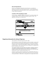
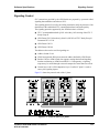
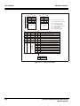
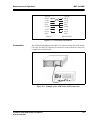
Location of FCC Compliance Labels
Labels stating the Centillion 1200N ATM Switch FCC registration number and
compliance with FCC Part 15 and 68 are attached to the Base Chassis. The
appearance of the labels is as shown below:
Regulatory Information for Analog Telephone
The equipment uses the following USOC jacks: RJ45.
If the equipment causes harm to the telephone network, the telephone company will
notify you in advance that temporary discontinuance of service may be required.
If advance notice is not practical, the telephone company will notify the customer
as soon as possible. Also, you will be advised of your right to file a complaint with
the FCC if you believe it is necessary.
The telephone company may make changes in its facilities, equipment, operations,
or procedures that affect the operation of the equipment. If this happens, the
telephone company will provide advance notice in order for you to make necessary
modifications in order to maintain uninterrupted service.
If trouble is experienced with this equipment, please contact NEC America, Inc.’s
National Technical And Support Center (NTAC) at 800-538-8166 for repair and/or
warranty information. If the trouble is causing harm to the telephone network, the
telephone company may request that you remove the equipment form the network
until the problem is resolved.
NO REPAIRS CAN BE DONE BY THE CUSTOMER.
IC CS03 Certification (Canada)
Certification number: 140 8642
Load Number of the equipment: N/A
NOTICE: The Industry Canada label identifies certified equipment. The
certification means that the equipment meets certain telecommunications network
protective operational and safety requirements. The department does not guarantee
the equipment will operate to the user’s satisfaction.
Before installing the equipment, users should ensure that it is permissible to be
connected to the facilities of the local telecommunications company. The
equipment must also be installed using an acceptable method of connection. In
some cases, the companies inside wiring associated with a single line individual
service may be extended by means of a certified connector assembly (telephone
extension cord). The customer should be aware that compliance with the above
conditions may not prevent degradation of service in some situation.
Repairs to certified equipment should b made by an authorized Canadian
maintenance facility designated by the supplier. Any repairs or installations made
by the user to this equipment, or equipment malfunctions, may give the
telecommunications company cause to request that the user disconnect the
equipment.
Users should ensure for their own protection that the electrical ground connections
of the power utility, telephone lines, and internal metallic water pipe system, if
present, are connected together. This protection may be particularly important in
rural areas.
CAUTION: Users should not attempt to make such connections themselves, but
should contact the appropriate electric inspection authority, or electrician, as
appropriate.
CAUTION: The act of monitoring or recording telephone conversations under
certain circumstances may violate federal or state statutes. Consultation with your
legal counsel prior to engaging in such practices would be advisable.
Safety Certifications
This equipment has been listed by Underwriters Laboratories and found to comply
with all the applicable requirements of the standard for Information Technology
equipment UL 1950 3rd edition. This equipment complies with CSA standard
C22.2 No 950 3rd edition.
Table of Contents
Table of Contents . . . . . . . . . . . . . . . . . . . . . . . . . . . . . . . . . . . . . . . . . . . i
Precautions on Handling the Product. . . . . . . . . . . . . . . . . . . . . . . . 1-1
Precautionary Messages . . . . . . . . . . . . . . . . . . . . . . . . . . . . . . . . . . . . . 1-1
Safety Measures . . . . . . . . . . . . . . . . . . . . . . . . . . . . . . . . . . . . . . . . . . . 1-2
Power Supply . . . . . . . . . . . . . . . . . . . . . . . . . . . . . . . . . . . . . . . . . . 1-2
Installation . . . . . . . . . . . . . . . . . . . . . . . . . . . . . . . . . . . . . . . . . . . . 1-2
Operating the Equipment . . . . . . . . . . . . . . . . . . . . . . . . . . . . . . . . . 1-3
User Responsibilities . . . . . . . . . . . . . . . . . . . . . . . . . . . . . . . . . . . . 1-3
Equipment Environment . . . . . . . . . . . . . . . . . . . . . . . . . . . . . . . . . . 1-3
Handling of Main Unit and Cables . . . . . . . . . . . . . . . . . . . . . . . . . . 1-4
PCMCIA Cards. . . . . . . . . . . . . . . . . . . . . . . . . . . . . . . . . . . . . . . . . 1-4
What is the Centillion 1200N Switch?. . . . . . . . . . . . . . . . . . . . . . . . 2-1
Features . . . . . . . . . . . . . . . . . . . . . . . . . . . . . . . . . . . . . . . . . . . . . . . . . . 2-1
Outside View of the ATM Switch . . . . . . . . . . . . . . . . . . . . . . . . . . . . . 2-3
Centillion 1200NSample System Configuration . . . . . . . . . . . . . . . . . . 2-4
What is ATM? . . . . . . . . . . . . . . . . . . . . . . . . . . . . . . . . . . . . . . . . . . . . 2-5
What is a Server Card? . . . . . . . . . . . . . . . . . . . . . . . . . . . . . . . . . . . . . . 2-7
LAN Emulation. . . . . . . . . . . . . . . . . . . . . . . . . . . . . . . . . . . . . . . . . . . . 2-8
ARP. . . . . . . . . . . . . . . . . . . . . . . . . . . . . . . . . . . . . . . . . . . . . . . . . . . . 2-10
Nomenclature and Functions . . . . . . . . . . . . . . . . . . . . . . . . . . . . . . . 3-1
Nomenclature of the ATM Switch . . . . . . . . . . . . . . . . . . . . . . . . . . . . . 3-1
Front View . . . . . . . . . . . . . . . . . . . . . . . . . . . . . . . . . . . . . . . . . . . . 3-1
Back View. . . . . . . . . . . . . . . . . . . . . . . . . . . . . . . . . . . . . . . . . . . . . 3-4
Description and Function of Components . . . . . . . . . . . . . . . . . . . . . . . 3-5
Switch/CPU Card . . . . . . . . . . . . . . . . . . . . . . . . . . . . . . . . . . . . . . . 3-5
Line Cards. . . . . . . . . . . . . . . . . . . . . . . . . . . . . . . . . . . . . . . . . . . . . 3-7
155 Mbps UTP5 Line Card. . . . . . . . . . . . . . . . . . . . . . . . . . . . . . . . 3-8
6.3 Mbps-J2 Line Card . . . . . . . . . . . . . . . . . . . . . . . . . . . . . . . . . . . 3-9
DS3 Line Card and E3 Line Card. . . . . . . . . . . . . . . . . . . . . . . . . . 3-10
Power Unit . . . . . . . . . . . . . . . . . . . . . . . . . . . . . . . . . . . . . . . . . . . 3-11
Fan Unit . . . . . . . . . . . . . . . . . . . . . . . . . . . . . . . . . . . . . . . . . . . . . 3-12
Slot Numbers . . . . . . . . . . . . . . . . . . . . . . . . . . . . . . . . . . . . . . . . . . . . 3-13
Line Numbers . . . . . . . . . . . . . . . . . . . . . . . . . . . . . . . . . . . . . . . . . . . . 3-14
Centillion 1200N ATM Switch User Manual
NTP 297-8103-903
i
Table of Contents
Hardware Specifications . . . . . . . . . . . . . . . . . . . . . . . . . . . . . . . . . . 4-1
Principal Functions of the ATM Switch . . . . . . . . . . . . . . . . . . . . . . . . . 4-1
Flow of ATM Cells. . . . . . . . . . . . . . . . . . . . . . . . . . . . . . . . . . . . . . . . . 4-2
Hardware Configuration and Overview of Functions. . . . . . . . . . . . . . . 4-3
Line Cards. . . . . . . . . . . . . . . . . . . . . . . . . . . . . . . . . . . . . . . . . . . . . 4-5
Interworking Cards . . . . . . . . . . . . . . . . . . . . . . . . . . . . . . . . . . . . . . 4-8
Server Cards . . . . . . . . . . . . . . . . . . . . . . . . . . . . . . . . . . . . . . . . . . . 4-9
Software Specifications. . . . . . . . . . . . . . . . . . . . . . . . . . . . . . . . . . . . 5-1
Connection Management . . . . . . . . . . . . . . . . . . . . . . . . . . . . . . . . . . . . 5-1
Signaling Control . . . . . . . . . . . . . . . . . . . . . . . . . . . . . . . . . . . . . . . . . . 5-3
Routing . . . . . . . . . . . . . . . . . . . . . . . . . . . . . . . . . . . . . . . . . . . . . . . . . . 5-4
ILMI Functions . . . . . . . . . . . . . . . . . . . . . . . . . . . . . . . . . . . . . . . . . 5-4
PNNI Functions . . . . . . . . . . . . . . . . . . . . . . . . . . . . . . . . . . . . . . . . 5-5
Traffic Management . . . . . . . . . . . . . . . . . . . . . . . . . . . . . . . . . . . . . . . . 5-6
Call Admission Control (CAC) . . . . . . . . . . . . . . . . . . . . . . . . . . . . 5-6
Usage Parameter Control (UPC). . . . . . . . . . . . . . . . . . . . . . . . . . . . 5-6
Congestion Control . . . . . . . . . . . . . . . . . . . . . . . . . . . . . . . . . . . . . . 5-7
Priority Control . . . . . . . . . . . . . . . . . . . . . . . . . . . . . . . . . . . . . . . . . 5-7
Shaping . . . . . . . . . . . . . . . . . . . . . . . . . . . . . . . . . . . . . . . . . . . . . . . 5-7
Monitoring . . . . . . . . . . . . . . . . . . . . . . . . . . . . . . . . . . . . . . . . . . . . 5-8
Hardware Management. . . . . . . . . . . . . . . . . . . . . . . . . . . . . . . . . . . . . . 5-8
Hardware Interface . . . . . . . . . . . . . . . . . . . . . . . . . . . . . . . . . . . . . . 6-1
UNI and NNI . . . . . . . . . . . . . . . . . . . . . . . . . . . . . . . . . . . . . . . . . . . . . 6-1
Line Interface . . . . . . . . . . . . . . . . . . . . . . . . . . . . . . . . . . . . . . . . . . . . . 6-2
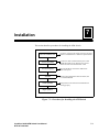
Installation . . . . . . . . . . . . . . . . . . . . . . . . . . . . . . . . . . . . . . . . . . . . . . 7-1
Installation Conditions . . . . . . . . . . . . . . . . . . . . . . . . . . . . . . . . . . . . . . 7-2
Environmental Conditions . . . . . . . . . . . . . . . . . . . . . . . . . . . . . . . . 7-2
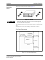
Installation Space . . . . . . . . . . . . . . . . . . . . . . . . . . . . . . . . . . . . . . . 7-3
Areas Suitable for Installation . . . . . . . . . . . . . . . . . . . . . . . . . . . . . 7-5
Checking the Package Contents and Preparation for Setting . . . . . . . . . 7-6
Packages . . . . . . . . . . . . . . . . . . . . . . . . . . . . . . . . . . . . . . . . . . . . . . 7-6
Packing List . . . . . . . . . . . . . . . . . . . . . . . . . . . . . . . . . . . . . . . . . . . 7-6
Tools and Equipment Necessary for Installation . . . . . . . . . . . . . . . 7-7
Transfer . . . . . . . . . . . . . . . . . . . . . . . . . . . . . . . . . . . . . . . . . . . . . . . 7-8
Mounting of Switch on Chassis . . . . . . . . . . . . . . . . . . . . . . . . . . . . . . . 7-9
Recommended Chassis . . . . . . . . . . . . . . . . . . . . . . . . . . . . . . . . . . . 7-9
Installing the Chassis Brackets . . . . . . . . . . . . . . . . . . . . . . . . . . . . 7-10
Installing the Shelf . . . . . . . . . . . . . . . . . . . . . . . . . . . . . . . . . . . . . 7-10
ATM Switch Installation . . . . . . . . . . . . . . . . . . . . . . . . . . . . . . . . 7-11
Connecting Communication Cables . . . . . . . . . . . . . . . . . . . . . . . . . . . 7-12
Types of Communication Cables . . . . . . . . . . . . . . . . . . . . . . . . . . 7-12
Connection . . . . . . . . . . . . . . . . . . . . . . . . . . . . . . . . . . . . . . . . . . . 7-13
MAT Connection . . . . . . . . . . . . . . . . . . . . . . . . . . . . . . . . . . . . . . 7-14
ii
Centillion 1200N ATM Switch User Manual
NTP 297-8103-903
Table of Contents
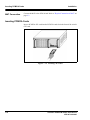
Inserting PCMCIA Cards . . . . . . . . . . . . . . . . . . . . . . . . . . . . . . . . . . . 7-14
Turning Power On and Off . . . . . . . . . . . . . . . . . . . . . . . . . . . . . . . . . . 7-15
Connecting the Power Cable. . . . . . . . . . . . . . . . . . . . . . . . . . . . . . 7-15
Turning the Power On. . . . . . . . . . . . . . . . . . . . . . . . . . . . . . . . . . . 7-16
Turning the Power Off . . . . . . . . . . . . . . . . . . . . . . . . . . . . . . . . . . 7-17
Power Source and Power Consumption . . . . . . . . . . . . . . . . . . . . . 7-17
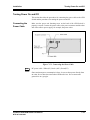
Setting System Configuration Data . . . . . . . . . . . . . . . . . . . . . . . . . . . 7-18
Operation Check . . . . . . . . . . . . . . . . . . . . . . . . . . . . . . . . . . . . . . . 7-18
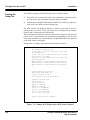
Line Interface Test . . . . . . . . . . . . . . . . . . . . . . . . . . . . . . . . . . . . . 7-19
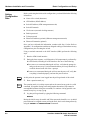
Basic Configuration and Setup . . . . . . . . . . . . . . . . . . . . . . . . . . . . . 8-1
Hardware Installation and Connection . . . . . . . . . . . . . . . . . . . . . . . . . . 8-1
Setting Configuration Data . . . . . . . . . . . . . . . . . . . . . . . . . . . . . . . . 8-2
Software Upgrading . . . . . . . . . . . . . . . . . . . . . . . . . . . . . . . . . . . . . . . . 8-4
Ongoing Configuration . . . . . . . . . . . . . . . . . . . . . . . . . . . . . . . . . . . . . . 8-5
Interface, ILMI, and SVC Signaling. . . . . . . . . . . . . . . . . . . . . . . . . 8-5
PVC Setup and Installation. . . . . . . . . . . . . . . . . . . . . . . . . . . . . . . . 8-8
Setting up LAN Emulation . . . . . . . . . . . . . . . . . . . . . . . . . . . . . . . . . . 8-10
SVC Tunneling . . . . . . . . . . . . . . . . . . . . . . . . . . . . . . . . . . . . . . . . . . . 8-14
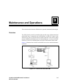
Maintenance and Operations. . . . . . . . . . . . . . . . . . . . . . . . . . . . . . . 9-1
Overview. . . . . . . . . . . . . . . . . . . . . . . . . . . . . . . . . . . . . . . . . . . . . . . . . 9-1
MAT and NMS . . . . . . . . . . . . . . . . . . . . . . . . . . . . . . . . . . . . . . . . . . . . 9-2
MAT . . . . . . . . . . . . . . . . . . . . . . . . . . . . . . . . . . . . . . . . . . . . . . . . . 9-2
Physical Connection of MAT . . . . . . . . . . . . . . . . . . . . . . . . . . . . . . 9-3
Connection . . . . . . . . . . . . . . . . . . . . . . . . . . . . . . . . . . . . . . . . . . . . 9-5
Communications Software . . . . . . . . . . . . . . . . . . . . . . . . . . . . . . . . 9-6
NMS . . . . . . . . . . . . . . . . . . . . . . . . . . . . . . . . . . . . . . . . . . . . . . . . . . . . 9-7
NMS Interface (via ATM) . . . . . . . . . . . . . . . . . . . . . . . . . . . . . . . . 9-8
NMS Interface (via Ethernet) . . . . . . . . . . . . . . . . . . . . . . . . . . . . . . 9-8
Periodic Maintenance . . . . . . . . . . . . . . . . . . . . . . . . . . . . . . . . . . . . . . . 9-9
Backing up Configuration Data . . . . . . . . . . . . . . . . . . . . . . . . . . . 9-10
Cosmetic Check . . . . . . . . . . . . . . . . . . . . . . . . . . . . . . . . . . . . . . . 9-11
Checking Cables and Connectors . . . . . . . . . . . . . . . . . . . . . . . . . . 9-11
Checking with MAT . . . . . . . . . . . . . . . . . . . . . . . . . . . . . . . . . . . . 9-11
Cleaning . . . . . . . . . . . . . . . . . . . . . . . . . . . . . . . . . . . . . . . . . . . . . 9-12
Modifications . . . . . . . . . . . . . . . . . . . . . . . . . . . . . . . . . . . . . . . . . . . 10-1
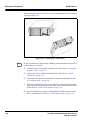
Moving the Equipment . . . . . . . . . . . . . . . . . . . . . . . . . . . . . . . . . . . . . 10-1
General Precautions on Handling Packages . . . . . . . . . . . . . . . . . . . . . 10-3
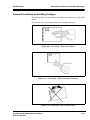
Power Unit Installation . . . . . . . . . . . . . . . . . . . . . . . . . . . . . . . . . . . . . 10-4
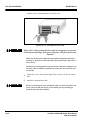
Inserting the Power Unit . . . . . . . . . . . . . . . . . . . . . . . . . . . . . . . . . 10-4
Removing the Power Unit. . . . . . . . . . . . . . . . . . . . . . . . . . . . . . . . 10-6
Switch/CPU Card Installation. . . . . . . . . . . . . . . . . . . . . . . . . . . . . . . . 10-7
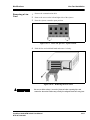
Inserting the Switch/CPU Card. . . . . . . . . . . . . . . . . . . . . . . . . . . . 10-7
Removing the Switch/CPU Card . . . . . . . . . . . . . . . . . . . . . . . . . . 10-8
Centillion 1200N ATM Switch User Manual
NTP 297-8103-903
iii
Table of Contents
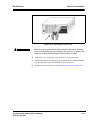
Line Card Installation . . . . . . . . . . . . . . . . . . . . . . . . . . . . . . . . . . . . . . 10-9
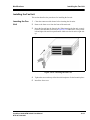
Inserting a Line Card . . . . . . . . . . . . . . . . . . . . . . . . . . . . . . . . . . . 10-9
Removing a Line Card . . . . . . . . . . . . . . . . . . . . . . . . . . . . . . . . . 10-11
Installing the Front Plate. . . . . . . . . . . . . . . . . . . . . . . . . . . . . . . . 10-12
Removing the Front Plate . . . . . . . . . . . . . . . . . . . . . . . . . . . . . . . 10-12
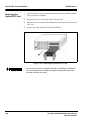
Installing the Fan Unit . . . . . . . . . . . . . . . . . . . . . . . . . . . . . . . . . . . . 10-13
Inserting the Fan Unit . . . . . . . . . . . . . . . . . . . . . . . . . . . . . . . . . . 10-13
Removing the Fan Unit. . . . . . . . . . . . . . . . . . . . . . . . . . . . . . . . . 10-14
Installing the Front Cover . . . . . . . . . . . . . . . . . . . . . . . . . . . . . . . . . . 10-15
Installing the Front Cover . . . . . . . . . . . . . . . . . . . . . . . . . . . . . . . 10-15
Removing the Front Cover . . . . . . . . . . . . . . . . . . . . . . . . . . . . . . 10-15
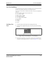
Upgrading Software . . . . . . . . . . . . . . . . . . . . . . . . . . . . . . . . . . . . . . 10-16
Inserting PCMCIA Cards . . . . . . . . . . . . . . . . . . . . . . . . . . . . . . . 10-16
Upgrading . . . . . . . . . . . . . . . . . . . . . . . . . . . . . . . . . . . . . . . . . . . 10-18
Adding Line Cards . . . . . . . . . . . . . . . . . . . . . . . . . . . . . . . . . . . . . . . 10-25
Preparation . . . . . . . . . . . . . . . . . . . . . . . . . . . . . . . . . . . . . . . . . . 10-25
Hardware Work. . . . . . . . . . . . . . . . . . . . . . . . . . . . . . . . . . . . . . . 10-25
Setting the ATM Switch and MAT. . . . . . . . . . . . . . . . . . . . . . . . 10-25
Hardware Check of the Additional Line Card . . . . . . . . . . . . . . . 10-25
Setting System Configuration Data . . . . . . . . . . . . . . . . . . . . . . . 10-25
Adding Hardware . . . . . . . . . . . . . . . . . . . . . . . . . . . . . . . . . . . . . . . . 10-26
Preparation . . . . . . . . . . . . . . . . . . . . . . . . . . . . . . . . . . . . . . . . . . 10-26
Setting the New ATM Switch. . . . . . . . . . . . . . . . . . . . . . . . . . . . 10-26
Hardware Work. . . . . . . . . . . . . . . . . . . . . . . . . . . . . . . . . . . . . . . 10-27
Troubleshooting . . . . . . . . . . . . . . . . . . . . . . . . . . . . . . . . . . . . . . . . 11-1
Error Detection . . . . . . . . . . . . . . . . . . . . . . . . . . . . . . . . . . . . . . . . . . . 11-1
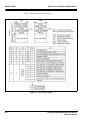
Detection by LED . . . . . . . . . . . . . . . . . . . . . . . . . . . . . . . . . . . . . . 11-2
Detection by Diagnosis . . . . . . . . . . . . . . . . . . . . . . . . . . . . . . . . . . 11-4
Troubleshooting Procedures . . . . . . . . . . . . . . . . . . . . . . . . . . . . . . . . . 11-5
When ALARM LED is Lighted (Hardware Error). . . . . . . . . . . . . 11-5
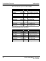
Alarm Error Numbers . . . . . . . . . . . . . . . . . . . . . . . . . . . . . . . . . . . 11-6
When RCV/INS is Lighted (Line Error). . . . . . . . . . . . . . . . . . . . 11-10
Error Messages . . . . . . . . . . . . . . . . . . . . . . . . . . . . . . . . . . . . . . . 11-11
Line Error Definition . . . . . . . . . . . . . . . . . . . . . . . . . . . . . . . . . . 11-12
Specifications and Standards . . . . . . . . . . . . . . . . . . . . . . . . . . . . . . . A-1
Glossary . . . . . . . . . . . . . . . . . . . . . . . . . . . . . . . . . . . . . . . . . . . . . . . . B-1
Worksheets . . . . . . . . . . . . . . . . . . . . . . . . . . . . . . . . . . . . . . . . . . . . . . . 1
iv
Centillion 1200N ATM Switch User Manual
NTP 297-8103-903
Table of Contents
This page is for your notes.
Centillion 1200N ATM Switch User Manual
NTP 297-8103-903
v
Table of Contents
vi
Centillion 1200N ATM Switch User Manual
NTP 297-8103-903
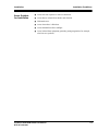
Precautions on Handling the Product
1
Precautionary Messages
This document uses the following symbols to alert you to safety issues that you
should observe to protect yourself and others from physical injury or property
damage.
The precautionary messages used in this manual have the following meanings. Be
sure to understand them before using the product.
When this sign is ignored and the product is used incorrectly, there is an
imminent danger that the user will suffer either death or serious injury.
When this sign is ignored and the product is used incorrectly, there is a possibility that the user will suffer either death or a serious injury.
When this sign is ignored and the product is used incorrectly, there is a possibility that the user will suffer an injury or cause property damage.
The symbols and signals used on the labels supplied with the product have the
following meanings. Be sure to understand them before using the product.
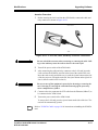
Class 1: Uses (safe) laser.
Keep the power cable disconnected when equipment is not in use.
Centillion 1200N ATM Switch User Manual
NTP 297-8103-903
1-1
Safety Measures
Precautions on Handling the Product
Safety Measures
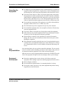
Power Supply
Installation
■
For safety, be sure to use a three-pin outlet for power supply with a grounding
receptacle. Lack of grounding may cause electric shock.
■
To prevent electric shock, do not touch the equipment with wet hands when it
is connected to a power supply.
■
Do not plug the power cable of this equipment into an outlet with excess load.
Putting excess load on one outlet may cause the outlet to overheat and start a fire.
■
Do not place a heater near the power cable, place a heavy object on the power
cable, or forcefully pull the power cable. Doing so may cause damage to the
power cable and cause electric shock or fire.
■
Place the equipment indoors.
■
Place the equipment where the temperature is 41 to 104°F (5 to 40°C) and
humidity is 10 to 80% (without condensation).
❑
1-2
Condensation happens when moisture in the air attaches to the surface of
metallic panels, etc., and turn into water drops. Condensation may occur
inside the equipment when the temperature inside the equipment is low and
the room temperature is high. Note that condensation may cause the
equipment to fail.
■
To prevent electric shock or a failure, do not place the equipment where it is
susceptible to such liquids as water and oil, steam, or where the humidity is high.
■
Place the equipment where the floor is flat and has adequate strength.
■
To prevent a failure or deformation, do not place the equipment where it is
exposed to direct sunlight or near fire or such heaters as stoves.
■
To prevent a failure, do not place the equipment in a dusty area.
■
Do not block the vents in the bottom, back, or top (rack mount) of the equipment.
Blocking the vents will cause the temperature in the equipment to rise and may
cause a failure or fire.
Centillion 1200N ATM Switch User Manual
NTP 297-8103-903
Precautions on Handling the Product
Operating the
Equipment
User
Responsibilities
Safety Measures
■
It is dangerous to use the equipment when it is malfunctioning. If you detect an
irregular condition (irregular noise, irregular odor, or smoke), immediately turn
off the main power, remove the power plug from the outlet, and call for service.
■
To prevent electric shock or a failure, do not pour liquid such as water inside
the equipment or touch the equipment with a wet hand. If liquid is accidentally
spilled inside the equipment, turn off the main power, remove the power plug
from the outlet, and call for service. Even if the equipment appears to be dry,
if there is liquid left inside the equipment, electric shock or a failure may result.
■
Do not touch any internal part of the equipment, or modify or disassemble the
equipment. Electric shock, fire, or a failure may result.
■
The ATM Switch is precision equipment. Keep it away from vibration.
■
Do not install the equipment where it is susceptible to vibration. Vibration may
cause the equipment to fail.
■
To prevent a failure, do not place any foreign objects inside the equipment.
■
Static electricity may cause the equipment to fail. To prevent damage from static
electricity, be sure the equipment is adequately grounded.
■
When touching a connector of the equipment, be careful of electrostatic
damage. Be sure to use an electrostatic prevention kit and wear gloves when
handling the equipment.
■
This equipment is normally used with its power on. No one other than the person
in charge of the system should touch the power switch. When power is turned
off, communications will be severed. In addition, all unsaved data settings will
be lost.
Once operation begins, the user need not control the equipment. The user merely
needs to carefully read the handling precautions in this chapter and provide an
environment around the equipment so the switch can function properly.
When an error occurs to the equipment during operation, the ALARM LED on the
front of the equipment will light. In this case, promptly call the system manager.
Equipment
Environment
■
Protect the equipment from excessive heat or cold. (Do not expose the
equipment to direct sunlight or place heat-radiating equipment near the switch.)
■
Ensure adequate ventilation.
■
Do not install the equipment where it is constantly humid or it is dusty.
■
Do not place a radio, television, or any other equipment that produces strong
magnetism near the ATM Switch.
Centillion 1200N ATM Switch User Manual
NTP 297-8103-903
1-3
Safety Measures
Handling of Main
Unit and Cables
PCMCIA Cards
1-4
Precautions on Handling the Product
■
Do not open the equipment or disassemble it.
■
Do not block ventilation holes or air-cooling fans.
■
Do not expose the equipment to strong shock or vibration.
■
Do not place heavy objects on the equipment.
■
Keep water, chemicals, etc., from coming in contact the equipment.
■
Keep foreign objects from entering the inside of the equipment.
■
Do not touch the reset switch or cable connections during operation.
■
Keep the cables from being at sharp angles.
The following precautions apply to PCMIA cards (if supplied):
■
Do not touch the card's terminal. Poor contact or failure may result.
■
Do not bend the card or subject it to external shock. Destruction of saved data
or a failure may result.
■
Store the card away from heat, moisture, or direct sunlight. These elements may
cause the card to deform or fail.
Centillion 1200N ATM Switch User Manual
NTP 297-8103-903
What is the Centillion 1200N Switch?
2
The Centillion 1200N is a compact desktop 2.5 Gbps ATM Switch.
At the core is an input/output buffer switch that realizes a 2.5 Gbps nonblocking
throughput. The ATM Switch can accommodate up to four lines of 622 Mbps
interface conforming to the ATM Forum and ITU-T recommendations and up to 16
lines of 155 Mbps interface.
XATOM (eXpandable ATM Output Modular Switch), the core of the ATM Switch,
is equipped with a large-capacity buffer to ensure the smooth flow of multimedia
traffic and provide a powerful support to multimedia communications.
The ATM Switch supports both fixed path, or permanent virtual connections
(PVC), and variable path, or switched virtual connections (SVC), and features such
functions as ATM cell priority control, congestion control, and traffic monitoring.
In addition, by using the SNMP protocol, the ATM Switch can interface with a
network management system (NMS).
Features
The ATM Switch is a desktop ATM switch used for such applications as LAN-toLAN connection. The ATM Switch serves as the core of an ATM users' network.
The features of the ATM Switch are described below.
■
Realizes 2.5 Gbps throughput
As the ATM Switch employs an output buffer type ATM switch with a
random access input-output buffer, it realizes high-capacity switching at a
high-speed total throughput of 2.5 Gbps of maximum switching capacity (at
155 Mbps × 16 lines maximum). Consequently, the ATM Switch can be used
to build a high-speed multimedia network.
■
Has redundant configuration
Redundant configuration of power unit ensures high reliability.
Centillion 1200N ATM Switch User Manual
NTP 297-8103-903
2-1
Features
What is the Centillion 1200N Switch?
■
Accommodates various ATM lines
The ATM Switch can interface various ATM lines by accommodating both
optical lines and metallic lines, different throughputs, and different protocols.
Because the ATM Switch is equipped with interfaces for various ATM lines, it
can be used for a wide range of multimedia applications depending on the
need.
■
Structure of the ATM Switch
With its compact dimensions, the ATM Switch can be placed on a desktop or
on a standard 19-inch rack. To facilitate on-site maintenance after the
operation begins, the ATM Switch is designed to allow service access from
the front of each unit.
■
Supports various connection functions
As the ATM Switch supports both fixed connections (PVCs) and switch
connections (SVCs), it provides various connection formats.
■
Connections may be set to one of five levels of control priority
❑
Total management of network
Because the ATM Switch is equipped with a network management agent
function based on SNMP, it can be managed along with such LAN products
as routers and hubs.
2-2
■
Traffic control
When competition occurs in sending out cells, this traffic control function
prevents the cell with a higher priority from being delayed or discarded.
Each connection may be set to one of five levels of control priority.
■
Supports PNNI Ver.1.0
The ATM Switch is the world's first ATM switch to support PNNI Ver.1.0 that
conforms to the ATM Forum. This ensures that network construction is made
simple.
■
Provides server function
By installing a server card (option) in the line card slot, the ATM Switch can
be used as a LAN emulation server or an ARP server.
■
Total management of network
As the ATM Switch is equipped with a network management agent function
based on SNMP, it can be managed along with such LAN products as routers
and hubs.
■
Interworking with other types of networks
Interworking between ATM network and other types of networks can be
realized by installing an interworking line card (Frame Relay card FR-DS1)
and a Circuit Emulation card (CE-DS1) in the ATM Switch.
Centillion 1200N ATM Switch User Manual
NTP 297-8103-903
What is the Centillion 1200N Switch?
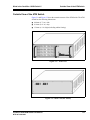
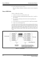
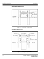
Outside View of the ATM Switch
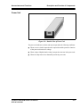
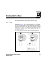
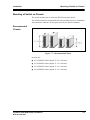
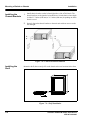
Outside View of the ATM Switch
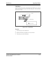
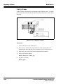
Figure 2-1 and Figure 2-2 show the external structure of the ATM Switch. The ATM
Switch has the following dimensions:
■
440 mm (17.3 in.) wide
■
410 mm (16.1 in.) deep
■
154 mm (6.1 in.) high (including rubber footing)
Figure 2-1: Front View
Figure 2-2: Back View (DC Power)
Centillion 1200N ATM Switch User Manual
NTP 297-8103-903
2-3
Centillion 1200NSample System Configuration
What is the Centillion 1200N Switch?
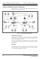
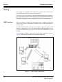
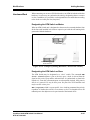
Centillion 1200NSample System Configuration
Explained in Figure 2-3 are LAN-to-LAN connection and ATM-LAN, which are
principal systems using the ATM Switch.
Centillion
Centillion
Centillion
Centillion
Figure 2-3: Sample System Configuration
LAN-to-LAN Connection
ATM Switch is used as the backbone network of a router (IP45) or a switching hub
(ATM Switch 3) for interworking such LANs as Ethernet, Token Ring, and FDDI.
In this case, the throughout is 2.5 Gbps.
A router or a switching hub with an ATM interface may be connected directly to
ATM Switch. Those without an ATM interface may be connected to the ATM
Switch via DSU.
ATM-LAN
By installing ATM-NIC on a PC (Personal Computer)/WS (Work Station) and
using ATM Switch, the LAN built with Ethernet, etc., can be used as an ATMLAN with maximum throughput of 2.5 Gbps.
2-4
Centillion 1200N ATM Switch User Manual
NTP 297-8103-903
What is the Centillion 1200N Switch?
What is ATM?
Method of Expansion
The number of lines accommodated can be increased by connecting a number of
ATM Switch units. Line interface can be used to connect the ATM Switch units. An
interface dedicated to connections between units is not necessary. When a number
of the ATM Switch units are connected to increase the number of lines, the actual
number of lines accommodated is the total number of lines less the number of lines
between the units.
What is ATM?
ATM, or Asynchronous Transfer Mode, is a communication method that will serve
as the basis for tomorrow's communication network, B-ISDN.
In ATM, all data in the network are exchanged in fixed-length, 53-byte blocks
called "cells." This allows much faster and broader communications compared to
the conventional STM or packet switching method.
The communication channels for cells are such virtual connections as VP (Virtual
Path) and VC (Virtual Channel). These are identified by the VPI (Virtual Path
Identifier) and VCI (Virtual Channel Identifier) stored in the 5-byte header of each
cell.
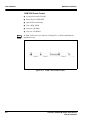
Figure 2-4 is a conceptual diagram of VP and VC in an ATM network, and the
format of ATM cells.
Figure 2-4: Virtual Path (VP) and Virtual Channel (VC)
Centillion 1200N ATM Switch User Manual
NTP 297-8103-903
2-5
What is ATM?
What is the Centillion 1200N Switch?
Figure 2-5 illustrates the ATM cell format.
Figure 2-5: ATM Cell Format
2-6
Centillion 1200N ATM Switch User Manual
NTP 297-8103-903
What is the Centillion 1200N Switch?
What is a Server Card?
What is a Server Card?
The Server Card is a CPU built-in card for realizing seamless connection with
existing LAN in an ATM network environment.
The card is mounted on ATM Switches, which serves as the core of an ATM
network, to provide LANE server, ARP server, and NHRP server functions.
Following are features of the server card:
■
Provides server functions conforming to various specifications
The software that provides the LAN emulation server functions is installed in
the card with a built-in CPU to facilitate the construction of LAN emulation.
By installing software with ARP server and NHRP server functions, it is
possible to eliminate bandwidth waste caused by conventional broadcast
address solution and improve the capacity of the network as a whole.
■
Hot-Swappable
The server card can be inserted into or removed from the ATM switching
system without affecting its switching functions.
■
Processor-to-processor communication function
Reciprocal communication is realized between the CPU in the server card and
the CPU in the switching system. This function allows the switching system
to control the server card and also to control in an integrated fashion the
switching system, along with other network equipment, with an NMS
(Network Management System).
■
Allows the installation of several server cards
A number of server cards can be installed on a single ATM Switch.
Consequently, this facilitates the scalable expansion of the server according to
network size and enables the server to be operated in a redundant
configuration. In addition, this feature makes it possible to distribute the
traffic that had concentrated in the server with conventional networks.
Centillion 1200N ATM Switch User Manual
NTP 297-8103-903
2-7
LAN Emulation
What is the Centillion 1200N Switch?
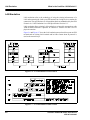
LAN Emulation
LAN emulation refers to the technology of using the existing infrastructure of a
LAN and connecting the LAN to an ATM network on a bridge level to emulate the
connection. The specification of LAN emulation has been standardized by the ATM
Forum in its “LAN Emulation Over ATM Specification Version 1.0.”
LAN emulation allows existing LAN terminals to reciprocally communicate with
ATM terminals and make it possible to construct a virtual LAN that is free of
physical restraints.
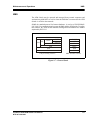
Figure 2-6 and Figure 2-7 show the LAN emulation protocol stack between an ATM
terminal and an existing LAN terminal and its frame format when IP protocol is
used as the network layer.
Figure 2-6: LAN Emulation Protocol Stack
Figure 2-7: LAN Emulation Frame Format
2-8
Centillion 1200N ATM Switch User Manual
NTP 297-8103-903
What is the Centillion 1200N Switch?
LAN Emulation
The server card provides the three server functions below to realize LAN
emulation.
■
LES (LAN Emulation Server)
LES provides the ARP (Address Resolution Protocol) function for solving an
ATM address from a MAC address. There is one LES for each ELAN
(Emulated LAN).
■
LECS (LAN Emulation Configuration Server)
LECS manages LAN emulation configuration and provides LES addresses. It
assigns a LEC (LAN Emulation Client; client that is a member of LAN
emulation) to a certain ELAN. There is one LECS for each management
domain.
■
BUS (Broadcast and Unknown Server)
BUS provides broadcast and multicast functions and solves unknown
destination addresses. There is one BUS for each ELAN (Emulated LAN).
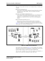
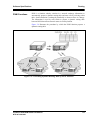
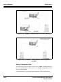
Figure 2-8 is a sample system configuration using the ATM Switch series switching
system and the server card (LAN Emulation Server).
Centillion
Centillion
Centillion
Centillion
Figure 2-8: Sample System Configuration
In the sample system configuration (Figure 2-8), such existing LANs as Ethernet,
and FDDI are connected to the ATM network by an ATM bridge. Here, the ATM
bridge and ATM terminal are equivalent to the LAN emulation client.
The server card is installed on one of the ATM switches in the illustration. A
number of server cards can be installed on a single ATM Switch.
Centillion 1200N ATM Switch User Manual
NTP 297-8103-903
2-9
ARP
What is the Centillion 1200N Switch?
ARP
Address Resolution Protocol (ARP) is an address conversion protocol used to
resolve the MAC address (or ATM address) of a terminal from its IP address in a
subnet. ARP provides IPOA function which conforms to RFC 1577.
The ARP function provided by the Server Card is to resolve the ATM addresses of
terminals in ATM-LAN. This function, in particular, is referred to as ATM ARP.
At least one ARP server is placed in a logical IP subnet (LIS). Having an ARP table
(IP address-ATM address chart) that is periodically updated, the ARP server
resolves addresses of terminals in that LIS.
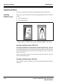
Shown in Figure 2-9 is the address resolution procedure using an ARP server. (The
numbers correspond with the procedures that follow.)
Figure 2-9: Address Resolution Procedure Using an ARP Server
1. Each terminal, when connected to ATM-LAN, registers its own IP address and
ATM address with the ARP server. The ARP server uses the registered
addresses to prepare an ARP table.
2. When the transmission terminal has no connection with the destination
terminal and has not cached the ATM address of the destination terminal, it
sends to the ARP server an address resolution request with the destination
terminal's IP address.
3. The ARP server, after receiving the address resolution request, checks the ARP
table to see if there is an entry corresponding to the IP address. If there is, the
ARP server notifies the terminal of the ATM address corresponding to the
received IP address.
2-10
Centillion 1200N ATM Switch User Manual
NTP 297-8103-903
What is the Centillion 1200N Switch?
ARP
4. The transmission terminal, after receiving the ATM address of the destination
terminal from the ARP server, uses the ATM address to establish a direct SVC
connection to the destination terminal. This SVC connection is used until the
data communication to the destination terminal is completed. When the
communication is completed, this SVC is released. (The ATM address of the
destination terminal obtained from the ARP server is cached in the
transmission terminal and retained for a certain duration.)
Centillion 1200N ATM Switch User Manual
NTP 297-8103-903
2-11
ARP
What is the Centillion 1200N Switch?
This page is for your notes.
2-12
Centillion 1200N ATM Switch User Manual
NTP 297-8103-903
Nomenclature and Functions
3
This chapter describes the names and functions of each part of the ATM Switch.
■
Nomenclature
■
Description and function of components
■
Slot number of each package
■
Line number
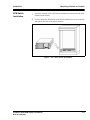
Nomenclature of the ATM Switch
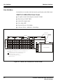
Front View
Power Unit
The power unit supplies power to the components of the ATM Switch. It draws DC
-40 to -58V as the power input. The power unit is installed on the top right-hand
side of the front of the ATM Switch. The power unit may be redundant.
Switch/CPU Card
This is the basic component of the ATM Switch. It is capable of switching ATM
cells at a maximum speed of 2.5 Gbps. It also controls the entire switch. The switch/
CPU card is installed on the bottom right-hand side of the front of the ATM Switch.
Front Plate
The Front Plate is installed in empty line card slots.
Fan Unit
The fan units force internal heat outside. The air flows from the right to left.
RS-232C Port
This is a 9-pin D-SUB connector used by service personnel to connect a
Maintenance and Administration Terminal (MAT).
Centillion 1200N ATM Switch User Manual
NTP 297-8103-903
3-1
Nomenclature of the ATM Switch
Nomenclature and Functions
Line Cards
Depending on the type of lines accommodated, line cards are available in variations
such as:
OC-12c
■
OC-3c/STM-4 (single mode)
■
OC-3c/STM1 (single mode/ multi-mode/UTP-5/COAX)
■
TAXI
■
6.3M-J2
■
45M-DS3
■
34M-E3
■
1.5M-DS1
■
2M-E1
■
FR-DS1
■
CE-DS1
■
CE-E1
■
The line cards provide line interfaces conforming to the ITU-T/ATM Forum. The
line cards terminate physical and ATM layers. The line cards are installed in the
line card slots in the front of the ATM Switch.
LANE server and IPOA ARP server functions can be used by installing a server
card in the line slot. LANE conforms to ATM Forum and IPOA to RFC1577.
Figure 3-1: Front View of the ATM Switch (front mask removed)
3-2
Centillion 1200N ATM Switch User Manual
NTP 297-8103-903
Nomenclature and Functions
Nomenclature of the ATM Switch
RESET Button
This is used to reset the switch/CPU card.
ALARM OUT
An external device for notifying the user of a problem with the ATM Switch (e.g.,
speaker or alarm lamp) is connected to this connector.
Power LED
The POWER LED lights green when power is on and turns off when power is off.
Ready LED
The READY LED turns on when the equipment is operating properly and turns off
when an error occurs. It also flashes during diagnosis.
Alarm LED
The ALARM LED lights red when an error occurs in the equipment.
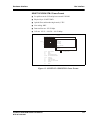
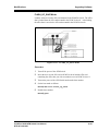
PCMCIA Card Slot
This slot is used to install an ATA (flash disk) card for storing software or system
configuration data or a LAN card (optional) for connecting the hardware to
Ethernet.
Centillion 1200N ATM Switch User Manual
NTP 297-8103-903
3-3
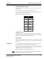
Nomenclature of the ATM Switch
Back View
Nomenclature and Functions
Power Switch
This switch is used to turn the ATM Switch on and off.
DC Power Connector
This connector is used to connect the power cable.
Power Unit Fastening Screw
This screw is used to fasten the power unit to the main unit and ground the ground
wire inside the main unit for safety.
Figure 3-2: Back View of the ATM Switch
3-4
Centillion 1200N ATM Switch User Manual
NTP 297-8103-903
Nomenclature and Functions
Description and Function of Components
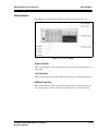
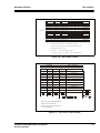
Description and Function of Components
Switch/CPU Card
Figure 3-3: Front View of the Switch/CPU Card
Power/Ready/Alarm Indicator Lights
These lamps indicate the status of the switch/CPU card.
POWER
READY
ALARM
Lighted
Power on
Off
Power off
Lighted
Operating properly
Flashing
Undergoing diagnosis
Off
Error occurred
Lighted
Error occurred
Off
Operating properly
RESET Button
This button is used to reset the switch/CPU card.
RS-232C Connector
This is a 9-pin D-SUB connector used by service personnel to connect a
Maintenance Administration Terminal (MAT).
ALARM Out
This connector is used to connect an external device for notifying the occurrence
of an irregular condition in the hardware (e.g., speaker or alarm notification lamp).
Centillion 1200N ATM Switch User Manual
NTP 297-8103-903
3-5
Description and Function of Components
Nomenclature and Functions
PCMCIA Card Slot
This slot is used to install a PCMCIA (ATA, LAN) card.
■
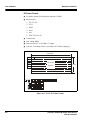
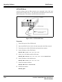
622 Mbps single mode line card
■
155 Mbps single mode (long) line card
Figure 3-4: Front View of 622 Mbps Single Mode and 155 Mbps Single
Mode (Long) Line Card
RCV/INS
Available for each line, these lamps indicate the status of that particular line.
RCV (red)
INS (green)
Status
Off
Lighted
Line status normal
Lighted
Off
Line error (reception error)
Off
Flashing
Line error (transmission error)
Off
Off
Hardware error
Rx/Tx
These codes indicate the reception side and transmission side of the SC connectors.
3-6
Rx
Reception side connector
Tx
Transmission side connector
Centillion 1200N ATM Switch User Manual
NTP 297-8103-903
Nomenclature and Functions
Line Cards
Description and Function of Components
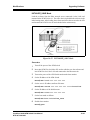
■
155 Mbps Multi-mode Line Card
■
155 Mbps Single Mode (short) Line Card
■
100 Mbps TAXI Line Card
Figure 3-5: Front View of 155 Mbps Multi-Mode, 155 Mbps Single Mode
(Short), and 100 Mbps TAXI Line Card
RCV/INS
Available for each line, these lamps indicate the status of that particular line.
RCV (red)
INS (green)
Status
Off
Lighted
Line status normal
Lighted
Off
Line error (reception error)
Off
Flashing
Line error (transmission error)
Off
Off
Hardware error
Rx/Tx
These codes indicate the reception side and transmission side of the SC connectors.
Centillion 1200N ATM Switch User Manual
NTP 297-8103-903
Rx
Reception side connector
Tx
Transmission side connector
3-7
Description and Function of Components
Nomenclature and Functions
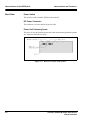
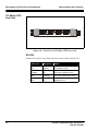
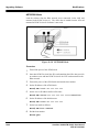
155 Mbps UTP5
Line Card
Figure 3-6: Front View of 155 Mbps UTP5 Line Card
RCV/INS
Available for each line, these lamps indicate the status of that particular line.
3-8
RCV (red)
INS (green)
Status
Off
Lighted
Line status normal
Lighted
Off
Line error (reception error)
Off
Flashing
Line error (transmission error)
Off
Off
Hardware error
Centillion 1200N ATM Switch User Manual
NTP 297-8103-903
Nomenclature and Functions
Description and Function of Components
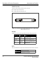
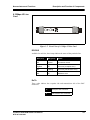
6.3 Mbps-J2 Line
Card
Figure 3-7: Front View of 6.3 Mbps-J2 Line Card
RCV/INS
Available for each line, these lamps indicate the status of that particular line.
RCV (red)
INS (green)
Status
Off
Lighted
Line status normal
Lighted
Off
Line error (reception error)
Off
Flashing
Line error (transmission error)
Off
Off
Hardware error
Rx/Tx
These codes indicate the reception side and transmission side of the BNC
connectors.
Centillion 1200N ATM Switch User Manual
NTP 297-8103-903
Rx
Reception side connector
Tx
Transmission side connector
3-9
Description and Function of Components
Nomenclature and Functions
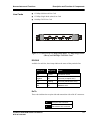
DS3 Line Card
and E3 Line Card
Figure 3-8: Front View of DS3 and E3 Line Card
RCV/INS
Available for each line, these lamps indicate the status of that particular line.
RCV (red)
INS (green)
Status
Off
Lighted
Line status normal
Lighted
Off
Line error (reception error)
Off
Flashing
Line error (transmission error)
Off
Off
Hardware error
Rx/Tx
These codes indicate the reception side and transmission side of the BNC
connectors.
3-10
Rx
Reception side connector
Tx
Transmission side connector
Centillion 1200N ATM Switch User Manual
NTP 297-8103-903
Nomenclature and Functions
Description and Function of Components
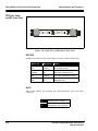
Power Unit
Figure 3-9: Outside View of Power Unit
The power unit indicates an alarm and stops output under the following conditions:
■
When excessive load is imposed on the output side and the protective function
of the power unit lowers the voltage.
■
When voltage of higher than the rating is output due to an error in the power unit.
■
When the temperature rises abnormally inside the power unit.
Centillion 1200N ATM Switch User Manual
NTP 297-8103-903
3-11
Description and Function of Components
Nomenclature and Functions
Fan Unit
Figure 3-10: Outside View of Fan Unit
Finger Guard
Protects users from injury.
Fastening Screws
These screws are used to fasten the fan unit to the shell.
3-12
Centillion 1200N ATM Switch User Manual
NTP 297-8103-903
Nomenclature and Functions
Slot Numbers
Slot Numbers
Slot numbers for each package of the ATM Switch are shown in Figure 3-11:
Figure 3-11: Slot Numbers
Power Unit Slot
When viewed from the front of the ATM Switch, slot #0 is to the left and slot #1 is
to the right.
Line Card Slot
When viewed from the front of the ATM Switch, slot #0 - 3 are from bottom to top.
PCMCIA Card Slot
When viewed from the front of the ATM Switch, slot #0 is at bottom and slot #1 is
at top. In principle, slot #0 is for the ATA card and slot #1 is for the LAN card.
Centillion 1200N ATM Switch User Manual
NTP 297-8103-903
3-13
Line Numbers
Nomenclature and Functions
Line Numbers
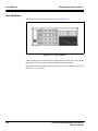
Line numbers of the ATM Switch are as shown in Figure 3-12.
Figure 3-12: Line Numbers
Each line number of the ATM Switch is composed of two digits. The left-most digit
indicates the line slot number and the last digit the position number.
Regardless of how many line ports are on a line card, the position numbers are, from
the left, #0, #1, #2, and #3.
3-14
Centillion 1200N ATM Switch User Manual
NTP 297-8103-903
Hardware Specifications
4
This section describes overview of the flow of ATM cell and each functional block
of the ATM Switch.
Principal Functions of the ATM Switch
„
Accommodates various ATM lines
The ATM Switch can interface various ATM lines by accommodating both
optical lines and metallic lines, different throughputs, and different protocols.
The ATM Switch is equipped with interfaces for various ATM lines.
„
Cell Switching
The ATM Switch identifies the destination ATM line using the cell header
information in the ATM cell sent over the ATM line, then sends the cell. The
ATM Switch has a switching capacity of 4 lines at 622 Mbps or, in throughput,
2.5 Gbps.
„
Fixed path setting
The path is normally set according to the connection information stored in the
PCMCIA ATA card. Path setting is changed by changing the connection
information from an external MAT. When the ATM Switch is reset, the path is
set according to the PVC connection information stored in the PCMCIA card
or the PVC connection information downloaded from an external source.
„
Variable path setting
The ATM Switch has a network address - line table to realize this function.
This table is automatically generated by ILMI function (dynamic routing table)
and/or set from a MAT (static routing table).
„
Traffic control
When competition occurs in sending out cells, this traffic control function
prevents the cell with a higher priority from being delayed or discarded.
Centillion 1200N ATM Switch User Manual
NTP 297-8103-903
4-1
Flow of ATM Cells
Hardware Specifications
„
Network management system interface
This unit exchanges maintenance information with the network management
system.
Flow of ATM Cells
The flow of ATM cells is as follows:
1. Cells sent over lines are received by the line cards.
2. The line cards generate switching information from the VPI, VCI, and PT in
the cell header.
3. The switch/CPU card outputs cells to the line cards corresponding to the
destination lines.
4. A line card that receives a cell converts the VPI, VCI, and PT in the cell header.
5. Cells are sent to the destination lines.
As an ATM switch, the switch/CPU card time-division multiplexes ATM cells from
the four line cards, uses AFs (address filters) to sort the input ATM cells according
to the destinations in their headers, then sends the ATM cells to the line cards. In
addition, the switch/CPU card is equipped with a CPU and has an interface with
MAT or NMS to perform hardware control, path connection control, and protocol
control.
Figure 4-1: ATM Switch
4-2
Centillion 1200N ATM Switch User Manual
NTP 297-8103-903
Hardware Specifications
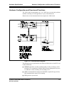
Hardware Configuration and Overview of Functions
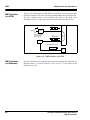
Hardware Configuration and Overview of Functions
The ATM switch accommodates up to 16 ATM lines per unit and performs
nonblock switching of fixed-length data (53 bytes) called ATM cells.
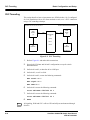
Shown below are the functional blocks that comprise the ATM Switch.
Figure 4-2: Functional Block Diagram
The principal processes performed in each functional block in the switch/CPU card
are described below.
■
GWPAD controls the assembly and disassembly of cells according to AAL5
when the CPU communicates with the NMS (Network Management System)
via ATM line or when switching cells according to SVC.
■
ASW is a functional block composed of ATOMSW (output buffer type switch).
This functional block controls cell switching.
■
CLK generates system clock.
Centillion 1200N ATM Switch User Manual
NTP 297-8103-903
4-3
Hardware Configuration and Overview of Functions
■
CPU is a card whose software operates to control the entire ATM Switch, and
is composed of a 64-bit RISC processor, main memory, flash memory, etc.
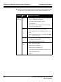
Hardware
Block
Switch/
CPU card
ASW
CLK
GWPAD
CPU
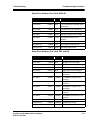
4-4
Hardware Specifications
Description of Functions
■
Cell switching control (point-to-point connection,
point-to-multipoint connection)
■
Five-class cell delay priority control
■
Cell alignment
■
Back Pressure (BP) sampling control/generation
control/multiplexing control
■
System clock generation and distribution
■
Self-running mode (self-running precision: +/- 4.6
ppm)
■
Slave mode (pull-in range: +/- 9.2 ppm, only lines
00 - 13 can be enslaved)
■
Cell assembly/disassembly control (transmission/
reception 512 connection)
■
DMA transfer control (burst access)
■
RISC processor installed
■
Main memory 32 Mbytes
■
Flash memory (PCMCIA card)
■
LAN interface control (Ethernet) (PCMCIA card)
■
SIO interface (RS-232C)
■
Clock
Centillion 1200N ATM Switch User Manual
NTP 297-8103-903
Hardware Specifications
Line Cards
Hardware Configuration and Overview of Functions
A line card is composed of a line interface unit and a line buffer.
Basically, the line interface unit physically terminates the lines. The line interface
unit takes ATM cells from the ATM line signals and sends the cells to the line buffer.
In addition, the line interface unit inserts the ATM cells from the line buffer into the
ATM line signals and sends the cells to the opposing hardware. In addition, the line
interface unit multiplexes and demultiplexes the ATM cells from a number of lines.
The principal functions performed by the line interface unit are as follows:
■
Conversion of electric signals and optical signals and detection of optical
reception signal disconnection.
■
Serial/parallel conversion.
■
Encode/decode or termination of each line frame.
■
Cell alignment and clock change (adjusts cell speed to line speed).
The line buffer converts into address number the data housed in the header of the
ATM cell received from the line interface unit and sends the cell to the ATM switch.
At the same time, the line buffer unit is equipped with an input buffer (IXB) that
stores ATM cells according to the BP (back pressure) from the switch engine.
Furthermore, the line buffer converts the address number in the header of the ATM
cell received from the ATM switch into data used by the opposing hardware and
sends the cell to the line terminating block. The line buffer is also equipped with an
output buffer (OXB) that stores ATM cells that are input in excess of the line speed.
The principal functions performed by the line buffer are as follows:
■
Valid VP bit count: 14 bits
■
Input-output buffers, each 32,000 cells in size
■
Congestion control (BP and EFCI functions)
■
Priority control (QoS 5 class, loss 2 class)
■
UPC control (GCRA)
■
OAM control (loop-back, F4/F5 error control)
■
Shaping (PCR & SCR guarantee type)
■
Frame discard (EPD)
Centillion 1200N ATM Switch User Manual
NTP 297-8103-903
4-5
Hardware Configuration and Overview of Functions
Hardware Specifications
Types of Line Cards
The line cards are available in several types, to suit the various lines accommodated.
While the line cards differ in a number of ways, such as the shape of connectors,
they basically function in the same way.
OC-12c
■
OC-3c/STM-4 (single mode)
■
OC-3c/STM1 (single mode/ multi-mode/UTP-5/COAX)
■
TAXI
■
6.3M-J2
■
45M-DS3
■
34M-E3
■
1.5M-DS1
■
2M-E1
■
FR-DS1
■
CE-DS1
■
CE-E1
■
4-6
Centillion 1200N ATM Switch User Manual
NTP 297-8103-903
Hardware Specifications
Hardware Configuration and Overview of Functions
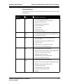
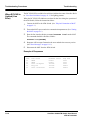
Functional Blocks
A functional description of each functional block in the line card is shown in the
following table.
Hardware
Block
Line card
PHY
MUX
ALT
IXB
OXB
Centillion 1200N ATM Switch User Manual
NTP 297-8103-903
Description of Functions
■
Conversion of physical media
(e.g., E/O conversion, O/E conversion)
■
Reception clock recovery
■
Transmission clock generation
■
Frame termination
■
Cell alignment
■
Speed conversion
■
Line loop-back control
■
Cell multiplexing/demultiplexing of multiple PHY
■
Cell loop-back control
■
SSO (Switch Specific Overhead) generation
(reception side)
■
Cell header conversion (transmission side)
■
Policing control
■
Flow monitor (e.g., passing cell count)
■
OAM function (Fault Management)
■
Cell storage buffer (32K cell buffer)
■
QoS five-class (CBR, rt-VBR, nrt-VBR, ABR, UBR)
■
Two-class cell loss priority control
■
EPD (Early Packet Discard)
■
BP (Back Pressure) reception control
■
Congestion notification control
■
Cell storage buffer (32K cell buffer)
■
QoS five-class (CBR, rt-VBR, nrt-VBR, ABR, UBR)
■
BP (Back Pressure) generation control
■
Broadcast cell control
■
ABR (ER control, binary mode)
■
Congestion notification control
■
Shaping
4-7
Hardware Configuration and Overview of Functions
Interworking
Cards
Hardware Specifications
The FR card and the CE card installed in the ATM Switch are equipped with a
function for interworking between ATM network and other types of networks.
The CE cards provide structured service and unstructured service in circuit
emulation. There are four types of CE cards:
CE-DS1
■
CE-J2
■
CE-DS3
■
CE-E1
■
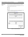
With CE-DS1, 8-bit channels are stored in DS1 frames and the DS1 frames can be
switched over to ATM cells depending on the type of service provided.
The frame format of CE-DS1 in shown in Figure 4-3.
Figure 4-3: CE-DS1 Frame Format
4-8
Centillion 1200N ATM Switch User Manual
NTP 297-8103-903
Hardware Specifications
Hardware Configuration and Overview of Functions
The CE-DS1 card conforms to the following recommendations and specifications:
Server Cards
■
ITU-T
G356, G362, G702, G703, G704, G709, G823, G824
■
ANSI
T1.102, T1.107A, T1.403, T1.408, T1.630, T1.627
■
Bellcore
TR-NWT-000170
■
ATM Forum
Circuit Emulation Service Interoperability Spec,
UNI Spec 3.1
A server card is composed of a server unit and an FR buffer.
The server unit is a basic component of the Server Card. Featuring a CPU with a
R4650 processor and flash memory, the server unit provides server functions and
controls the Server Card.
The FR buffer realizes a communication function between the Server Card's CPU
and the switching system's CPU. Inter-processor communication is realized by
FRCTL-LSI, via the inter-processor message communication table on the
SDRAM.
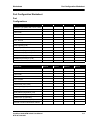
Shown below are the specifications of the server card:
CPU R4650
CLK 100MHz
Cache Memory 8KB+8KB
DRAM 16MB
Flash Memory (ROM) 2MB
Flash Memory (FILE) 8MB
Interface
PCI BUS 33MHz
RS232C
Ethernet 10BaseT
Redundancy configuration Redundant
Centillion 1200N ATM Switch User Manual
NTP 297-8103-903
4-9
Hardware Configuration and Overview of Functions
Hardware Specifications
This page is for your notes.
4-10
Centillion 1200N ATM Switch User Manual
NTP 297-8103-903
Software Specifications
5
This section briefly describes the functions of the ATM Switch.
As a core entity in an ATM network, the ATM Switch provides a variety of
functions to sustain and operate the network most efficiently and at high quality.
Here, the following functions of the ATM Switch are explained.
■
■
■
■
■
Connection Management
Signaling Control
Routing
Traffic Management
Hardware Management
Connection Management
The ATM Switch supports both fixed connections (PVCs) and variable connections
(SVCs).
PVC is a fixed connection that is manually established on the ATM Switch.
Normally, the connection is established according to the connection information
stored in the PCMCIA ATA card. The connection establishment can be changed by
changing the connection information from an external MAT. When the ATM
Switch is reset, the connection is established according to the PVC connection
information stored in the PCMCIA ATA card or PVC connection information
downloaded from an external source.
SVC is a variable connection that is prepared by a protocol called signaling that
establishes and releases SVCs. The ATM Switch maintains a network address - line
correspondence table to realize the best suited SVC routing for the given network
condition. This table is generated and changed manually (static routing table), or
automatically generated by the ILMI function and the PNNI function (dynamic
routing table).
Both types of connection can be set to either point-to-point connection or point-tomultipoint connection.
Centillion 1200N ATM Switch User Manual
NTP 297-8103-903
5-1
Connection Management
Software Specifications
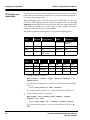
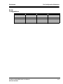
The number of connections per system is as follows:
■
Point-to-point (PVC):
8,000 connections
■
Point-to-multipoint (PVC): 1,000 connections
■
Point-to-point (SVC):
■
Point-to-multipoint (SVC): 1,000 end points
4,000 connections
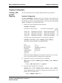
The ATM Switch also supports two connections, Soft PVC and tunneling, that take
advantage of the characteristics of PVC and SVC mentioned above.
Soft PVC is a PVPC (Permanent Virtual Path Connection) or a PVCC (Permanent
Virtual Circuit Connection) that is established by SVC procedure over several
switches.
The ATM Switch allows the user to register up to 64 Soft PVCs. To use the Soft
PVC service, the remote side switch must be a NETNEX ATM Switch.
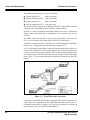
Tunneling is a connection that is established over a PVP (Permanent Virtual Path)
network (e.g., existing public network that does not support SVC).
A VP (Virtual Path) is established in a physical link that connects the switches in a
PVP network, and the VP is used as a tunneling path. The switch (edge switch) that
is adjacent to the PVP network establishes PVCs in the tunneling path and sends
SVC setup messages. The ATM Switch allows the user to register up to 64 tunneling
paths. Figure 5-1 is a conceptual diagram of the connections supported by the ATM
Switch.
Figure 5-1: The ATM Switch Connections
Connections are established by inputting commands from a MAT connected to the
ATM Switch. The information on the established connection can be read by a
command from the MAT or sending a GET request from an NMS. (For details on
the commands, refer to the ATM Command Manual.)
5-2
Centillion 1200N ATM Switch User Manual
NTP 297-8103-903
Software Specifications
Signaling Control
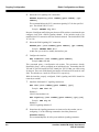
Signaling Control
SVC connections provided by the ATM Switch are prepared by a protocol called
signaling that establishes and releases SVCs.
The signaling protocol is used by the calling terminal to notify the network of the
destination of the established SVC, communication band, and traffic quality.
The signaling protocols supported by the ATM Switch are as follows:
■
ITU-T recommendation draft Q.2931 at the May 1993 meeting of the ITU-T
Study Group II.
■
ATM Forum UNI 3.0 based on Q.SAAL1 (SSCOP) of ITU-T Study Group 11
Document DT/11/3-28.
■
ATM Forum UNI 3.1
■
ATM Forum UNI 4.0
The addresses that can be used for signaling are:
■
Address format E.164.
■
NSAP incorporated ATM private network address defined by ATM Forum.
■
Besides UNI, the ATM Switch also supports routing function and signaling
function conforming to ATM Forum PNNI 1.0. Consequently, a signaling
request may be routed through a network composed of more than one switch.
■
Control layer AAL5 (ATM Adaptation Layer 5) called "C plane" is used to
convey the signaling request.
Figure 5-2 shows the protocol stack of the C plane.
Figure 5-2: Protocol Stack of C plane
Centillion 1200N ATM Switch User Manual
NTP 297-8103-903
5-3
Routing
Software Specifications
Routing
The signaling for establishing SVC connections is transferred by referring to the
routing table maintained by each switch in the network.
There are two types of routing table: static routing table and dynamic routing table.
the ATM Switch provides the ILMI (Integrated Local Management Interface) and
PNNI (Private Network-Network Interface) functions for preparing and revising
the dynamic routing tables. Static routing tables can also be revised manually.
ILMI Functions
ILMI is a function for learning the configuration data of neighboring equipment
when an end system is connected to a switch or when a switch is connected to
another switch.
The ILMI function includes a switch-terminal address registration function. This
function is triggered by a trap. The switch adds the inherent address of each
terminal to its network prefix and registers the result as the ATM address of each
terminal.
A switch prepares dynamic routing tables by this address registration function.
Figure 5-3 illustrates the procedure of ILMI address registration.
Figure 5-3: ILMI Address Registration
5-4
Centillion 1200N ATM Switch User Manual
NTP 297-8103-903
Software Specifications
PNNI Functions
Routing
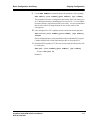
PNNI is a function whereby switches in a network exchange information to
automatically prepare a dynamic routing table and route cells by referring to that
table. Such information is exchanged periodically or whenever there is a change.
The information is used by each switch to prepare a dynamic routing table
between PNNIs that reflects network status in a timely fashion.
Figure 5-4 illustrates the procedure by which the PNNI function prepares a
dynamic routing table.
Centillion
Centillion
Figure 5-4: Generating Dynamic Routing Table by PNNI Function
Centillion 1200N ATM Switch User Manual
NTP 297-8103-903
5-5
Traffic Management
Software Specifications
Traffic Management
The ATM Switch provides the following traffic management functions.
■
Call Admission Control
■
Usage Parameter Control
■
Congestion Control
■
Priority Control
■
Shaping
■
Monitoring
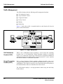
Figure 5-5 shows how traffic is controlled and how each function fits into the
process in the ATM Switch.
Figure 5-5: Traffic Management
Call Admission
Control (CAC)
When a SVC establishment request signaling is received from the originating
terminal, CAC, or Call Admission Control, determines whether to accept that
request. CAC checks the current usage of the network to determine whether the
communication band and traffic quality requested by that SVC can be satisfied,
then decides whether to establish the connection.
Usage Parameter
Control (UPC)
UPC, or Usage Parameter Control, monitors whether the traffic of the user’s
communication in progress has exceeded the band declared in the request for SVC
establishment. This control is necessary to prevent deterioration to the quality of
the communications of the user and other users in the network.
The ATM Switch employs a six-stage parameter control using the dual leaky
bucket method.
5-6
Centillion 1200N ATM Switch User Manual
NTP 297-8103-903
Software Specifications
Congestion
Control
Traffic Management
In the ATM Switch, congestion is controlled by applying a back pressure in the
direction of line output unit » switch » line input unit and restricting the number of
incoming cells. The ATM Switch also supports congestion control using Explicit
Forward Congestion Indicator (EFCI) and RM (Resource Management) cell.
Furthermore, the ATM Switch controls congestion from ABR/UBR class traffic
by using EPD (Early Packet Discard), or a function that discards cells in frame
increments when the input buffer is congested.
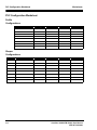
Priority Control
The ATM Switch performs the five classes of controls below on traffic delay:
■
CBR (Constant Bit Rate service)
■
rt-VBR (Variable Bit Rate service (real time))
■
nrt-VBR (Variable Bit Rate service (non real time))
■
ABR (Available Bit Rate service)
■
UBR (Unspecified Bit Rate service)
In this list, the higher the control, the better the delay characteristics. Priority is
given to CBR and rt-VBR traffic as they are transmitted ahead of other classes of
traffic.
These delay priorities can be selected for each connection when establishing the
connection.
In the switch, a cell delay of no less than 40 µsec occurs depending on the degree
of passing cell congestion and the degree of priority.
The ATM Switch performs two classes of controls on cell loss. Cell loss priority
control is performed in cell increments based on the CLP bit value in the header of
each cell. The definition of CLP bit value is as follows:
■
CLP bit "0" (high priority)
■
CLP bit "1" (low priority)
In the ATM Switch, to ensure traffic quality, every line card shares one input
buffer (32,000 cell capacity) and one output buffer (32,000 cell capacity).
Shaping
Shaping is a function that schedules cell transfer so it complies with the
communication rate and traffic parameters declared by each connection. This
function ensures that even bursty data are transferred at a consistent rate without
being discarded and that the network bands are used efficiently.
The ATM Switch allows one of eight stages of shaping to be set for each port.
Centillion 1200N ATM Switch User Manual
NTP 297-8103-903
5-7
Hardware Management
Monitoring
Software Specifications
Monitoring is a function that reads the cell counter of the hardware. It checks the
total number of cells exchanged in the ATM Switch, the number of error cells, and
the number of discarded cells, etc.
NOTE
When an overflow occurs (at 4 billion+ cells), the cell counter stops counting
cells.
The information on the ATM Switch traffic and performance can be checked for
each line, connection, or line physical level by inputting the command
DISPLAY traffic from a MAT. For details on the DISPLAY traffic
command, refer to the appropriate Command Manual.
Hardware Management
The hardware management unit controls the following:
■
Static hardware configuration
■
Dynamic hardware configuration (operation status management)
■
Hardware revision
■
Software revision
■
Own IP address
■
NMS address
■
Connection-related parameter control (e.g., the number of VPIs of the line)
These pieces of information are stored in a database called a Management
Information Base (MIB). Information stored in the MIB can be set and read from
a MAT.
The NMS uses Simple Network Management Protocol (SNMP) to access the MIB
of each device in the network and centrally manage faults and configuration data
of the devices.
5-8
Centillion 1200N ATM Switch User Manual
NTP 297-8103-903
6
Hardware Interface
This chapter describes the line interfaces that the ATM Switch supports.
UNI and NNI
As illustrated in Figure 6-1, there are two types of interfaces in an ATM network.
One is the User Network Interface (UNI) that connects an end system (a router, for
example) to an ATM switch. The other is the Network Node Interface (NNI) that
connects two ATM switches. These interfaces are further classified into public
network interface and private network interface, depending on the type of the
network they are connected to.
The ATM Switch provides various line cards to accommodate these interfaces.
Centillion
Centillion
Centillion
Centillion
Figure 6-1: ATM Network Interface
Centillion 1200N ATM Switch User Manual
NTP 297-8103-903
6-1
Line Interface
Hardware Interface
Line Interface
Provided below is an outline of the line interface specifications of the ATM Switch:
SONET OC-12/SDH STM-4 Frame Format
■
For public network UNI and private network UNI/NNI
■
Physical layer: SONET PMD
■
Optical fiber (single mode)
■
Line coding: NRZ
■
Data rate/line rate: 622.08 Mbps
■
Cell rate: 622.08 × 1040/1080 = 599.04 Mbps
S T M -4 fra m e
V C -4-4C
MSOH
9R O W S
AU
PO IN TE R
RSOH
1 2B ytes
A1
B1
D1
H1
B2
D4
D7
D 10
Z1
1 08 0B ytes
1 2B ytes
4 B yte s
1 2B ytes
A1
A1
H 1*
B2
H 1*
B2
Z1
Z1
A2
E1
D2
H2
K1
D5
D8
D 11
Z2
A2
A2
H 2*
H 2*
Z2
Z2
C1
F1
D3
H3
K2
D6
D9
D 12
E2
1 04 4B ytes
8 B yte s
C1
C1
C1
C 1*
C 1*
H3
H3
H3
H3
H3
4 B yte s
H 1 * :1 0 0 1 S S 11 (S S b it,in c lu d in g H 1 , is set 1 /O O C 1 2 = "0 0 " S T M -4 = "1 0 ")
H 2 * :11111111
C 1 * :U n assig n e d b y te(1 0 1 0 1 0 1 0 = N T T sp ecific atio n (S T M -4 ) fix ed )
:U n a ssig n ed b y te(A L L "0 ") < O C 1 2 sp ec ificatio n fix ed >
J1
B3
C2
G1
F2
H4
Z3
Z4
Z6
F IX E D
S TU F F
1 04 4B ytes
V C -4-4C PAY L O A D
A fte r 2 b y te s o f E 1 ,E 2 ,D 1 -D 1 2 ,an d Z 1
Z 2 # 1 ,Z 2 # 2 ,Z 2 # 4 -Z 2 # 1 2 ,J1 ,F 2 ,Z 3 -Z 5 :A L L "1 "
F IX E D S T U F F :A L L "1 "
Figure 6-2: SONET OC-12/SDH STM-4 Frame Format
6-2
Centillion 1200N ATM Switch User Manual
NTP 297-8103-903
Hardware Interface
Line Interface
SONET OC3/SDH STM-1 Frame Format
■
For public network UNI and private network UNI/NNI
■
Physical layer: SONET PMD
■
Optical fiber (multi mode/single mode), UTP5
■
Line coding: NRZ
■
Data rate/line rate: 155.52 Mbps
■
Cell rate: 155.52 × 260/270 = 149.76 Mbps
27 0 B ytes
9 B ytes
A1 A1 A1 A2 A2 A2 C1 C1 C1
E1
F1
B1
D1
D2
D3
A U -4 po inter
B2 B2 B2 K1
K2
D4
D5
D6
D7
D8
D9
D 10
D 11
D 12
Z1 Z1 Z1 Z2 Z2 Z2 E2
A 1,A 2
B1
B2
C1
D 1-D 1 2
E 1 ,E 2
F1
K1
K2
Z1
Z2
J1 P ath Trace
B 3 B IP -8
C 2 P ath Iden tifier
G 1 E rror R epo rt
F 2 U ser C hann el
H 4 H eader C ell In dicato r
Z 3 R eserv ed
Z 4 R eserv ed
Z 5 R eserv ed
:F ram e alignm en t
:B IP -8
:B IP -24
:S T M fram e identification
:D ata co m m u nicatio n ch an nel
:O rd er w ire
:U ser ch annel
:C hang e-ov er co ntro l
:C hang e-ov er co ntro l,A IS /R D I
:R eserv ed
:F E B E
A1
:B its activ e in U N I
Figure 6-3: SONET OC-3/SDH STM-1 Frame Format
Centillion 1200N ATM Switch User Manual
NTP 297-8103-903
6-3
Line Interface
Hardware Interface
100M TAXI Frame Format
NOTE
■
For private network UNI/NNI
■
Physical layer: FDDI PMD
■
Optical fiber: multi mode
■
Line coding: 4B/5B
■
Data rate: 100 Mbps
■
Line rate: 125 Mbaud
In 100M TAXI, there is no frame for existing STM. A field is established for
aligning the cells.
Figure 6-4: 100M TAXI Frame Format
6-4
Centillion 1200N ATM Switch User Manual
NTP 297-8103-903
Hardware Interface
Line Interface
6.3M-J2 Frame Format
■
For public network UNI
■
Physical layer: TTC standard JT-G703-a
■
Coaxial cable
■
Line coding: NRZ
■
Data rate/line rate: 6.312 Mbps
■
Cell rate: 6.144 Mbps
■
Cell alignment: HEC is used
Figure 6-5: Secondary Speed Interface (6.3M) Frame Format
Centillion 1200N ATM Switch User Manual
NTP 297-8103-903
6-5
Line Interface
Hardware Interface
DS3 Frame Format
■
For public network UNI and private network UNI/NNI
■
Physical layer:
❑
ITU-T G703
❑
G804
❑
I432
❑
ANSI T1.102-1933
❑
T1.107a-1990
❑
T1.404-1994
❑
T1.646-1995
❑
Bellcore TR-NWT-001112
❑
TR-NWT-000499
■
Coaxial cable
■
Line coding: B3ZS
■
Data rate/line rate: 44.736 Mbps
■
Cell rate: 44.21 Mbps (Direct Mapping), 40.70 Mbps (PLCP)
Figure 6-6 and Figure 6-7 illustrate DS3 frame format and DS3 PLACP frame
format.
6-6
Centillion 1200N ATM Switch User Manual
NTP 297-8103-903
Hardware Interface
Line Interface
16-bit 84-bit
S ubfram e
680-bit
X IN F O .P Y LD . F 1 IN F O .P Y LD . C IN F O .P Y LD . F 0
C
F0
C
IN F O .P Y LD .
X IN F O .P Y LD . F 1 IN F O .P Y LD . C IN F O .P Y LD . F 0
C
F0
C
IN F O .P Y LD .
P IN F O .P Y LD . F 1 IN F O .P Y LD . C IN F O .P Y LD . F 0
C
F0
C
IN F O .P Y LD .
P IN F O .P Y LD . F 1 IN F O .P Y LD . C IN F O .P Y LD . F 0
C
F0
C
IN F O .P Y LD .
M 0 IN F O .P Y LD . F 1 IN F O .P Y LD . C IN F O .P Y LD . F 0
C
F0
C
IN F O .P Y LD .
M 1 IN F O .P Y LD . F 1 IN F O .P Y LD . C IN F O .P Y LD . F 0
C
F0
C
IN F O .P Y LD .
M 0 IN F O .P Y LD . F 1 IN F O .P Y LD . C IN F O .P Y LD . F 0
C
F0
C
IN F O .P Y LD .
7 S ubfram e, each w ith 680 bits = 1 M -F ram e w ith 4760 bytes
IN F O .P Y LD .(Inform ation P ayload)= 4704 bytes available for the P LC P
E ach IN FO .P Y LD .block = 84 bits
T he sym bol . . . represents an IN FO .P Y LD .block
...
X , F n (w here n = 1001 ), C , P, M n (w here n = 010) = D S 3 O verhead B it
Figure 6-6: DS3 Frame Format
P L C P F ram in g
0 µ sec
A1
A2
A1
A2
A1
A2
A1
A2
A1
A2
A1
A2
A1
A2
A1
A2
A1
A2
A1
A2
A1
A2
A1
A2
PO I
PO H
P L C P P ay lo ad
P 11
P10
P9
P8
P7
P6
P5
P4
P3
P2
P1
P0
Z6
Z5
Z4
Z3
Z2
Z1
X
B1
G1
X
X
C1
F irst AT M C ell
AT M C ell
AT M C ell
AT M C ell
AT M C ell
AT M C ell
AT M C ell
AT M C ell
AT M C ell
AT M C ell
AT M C ell
Tw elfth AT M C ell
5 3 o ctets
P O I : P ath O v erh ead In d icato r
P O H : P ath O v erh ead
B IP 8 : B it In terleav ed P arity - 8
X : U n assig n ed
Figure 6-7: DS3 PLCP Frame Format
Centillion 1200N ATM Switch User Manual
NTP 297-8103-903
6-7
Line Interface
Hardware Interface
E3 Frame Format
■
For public network UNI and private network UNI/NNI
■
Physical layer
❑
ITU-T G703
❑
G751
❑
G804
❑
G832
❑
I432
❑
ETSI T/NA (91)18
■
Coaxial cable
■
Line coding: HDB3
■
Data rate/line rate: 34.368 Mbps +/-20ppm
■
Cell rate: 33.92 Mbps (G832), 34.01 Mbps (G751 Direct Mapping)
59 octets
FA 1 FA 2
EM
TR
MA
NR
GC
53 0 octe ts
pa yload
9 ro w s
Figure 6-8: G.832 E3 Frame Format
6-8
Centillion 1200N ATM Switch User Manual
NTP 297-8103-903
Hardware Interface
Line Interface
J
FA S : F ram e align m e nt sig nal
R A I : A la rm indica tio n to the rem o te d igita l m ultiplex eq uipm e nt
N .U : B it reserved for na tio nal use
JS B : Justification se rvice bits
B TA J : B its from trib utaire a va ilable fo r justification
Figure 6-9: G.751 E3 Frame Format
1
A1
A1
A1
A1
A1
A1
A1
A1
A1
1
A2
A2
A2
A2
A2
A2
A2
A2
A2
A 1,A 2
P 0-P 8
C1
M 1,M 2
G1
B1
F1
Z 1-Z 3
1
P8
P7
P6
P5
P4
P3
P2
P1
P0
:
:
:
:
:
:
:
:
1
Z3
Z2
Z1
F1
B1
G1
M 2(1)
M 1(2)
C1
53 octets
F irst ATM C ell
ATM C ell
ATM C ell
ATM C ell
ATM C ell
ATM C ell
ATM C ell
ATM C ell
Last ATM C ell
18(17) to 20(21) octets
Trailer
125 s
fram ing octets.
path overhead idenfier octet.
cycle stuff c ounter.
D Q D B layer m anagem ent inform ation oc tets.
P LC P path status.
B it Interleaved P arity-8 (B IP -8) .
P LC P path user channel.
grow th octets.
Figure 6-10: G.832 (G.751) E3 PLCP Frame Format
Centillion 1200N ATM Switch User Manual
NTP 297-8103-903
6-9
Hardware Interface
p aylo ad 4 8 B yte
ce ll 5 3 B yte
he ad e r 5 B yte
Line Interface
G FC
0
0
0
0
0
0
0
0
NNI
UNI
MSB
LS B
MSB
LS B
V P I(8)
G F C (4) V P I(4)
V P I(4) V C I(4)
V P I(4) V C I(4)
V C I(8)
V C I(8)
CLP
V C I(4) P T (3) (1)
V C I(4) P T (3) (1)
H E C (8)
H E C (8)
U se r Inform a tion
VPI
0
x
x
x
x
x
x
x
VCI
0
1
2
3
4
5
16
an y
value
othe r
than
0
U se r Inform a tion
PT
x
0,2
0-3
0,2
0,2
0-3
0
1
2
3
4
5
6
7
CLP
0
*
*
*
*
*
*
*
*
*
*
*
*
*
*
0
1
CLP
U N I: U ser-N e tw ork In te rface
N N I: N etw ork-N etw ork Interface
G FC :
V P I:
V C I:
P T:
CLP:
HEC:
G ene ric F low C o ntrol
V irtu al P ath Ide ntifier
V irtual C han ne l Id entifie r
P ayloa d Type
C ell Lo ss P rio rity
H e ade r E rro r C on trol
use
un assig ned cell
m eta sig nallin g (de fa ult V P I= 0 )
ge nera l bro adcas t sig nallin g (defau lt V P I= 0 )
seg m ent O A M F 4
en d-to-en d O A M F 4
po int-to-p oint sig nallin g (defau lt V P I= 0)
ILM I (Inte rim L oca l M a nag em e nt Inte rfac e)
use r d ata cell, n o cong estion , S D U -typ e= 0
use r d ata cell, co nge stion, S D U -type = 1
use r d ata cell, co nge stion, S D U -type = 0
use r d ata cell, n o cong estion , S D U -typ e= 1
seg m ent O A M F 5
en d-to-en d O A M F 5
rese rved for tra ffic con t. an d resou rce m an.
rese rved
no rm al priority
lo w er priority
Figure 6-11: ATM Cell Format
6-10
Centillion 1200N ATM Switch User Manual
NTP 297-8103-903
7
Installation
This section describes procedures for installing the ATM Switch.
Move to installation site
Check the contents of the package and move the ATM
Switch to installation site or mount on optional chassis.
Connect the cables
Connect the cables (communications power cable
and RS 2320 cable) to the ATM Switch. Connect
MAT to the other end of the RS-232C cable.
Turn on the power
Insert the PCMCIA card into the ATM Switch.
Turn on the power.
Set data
Set the system configuration data. For details, refer
to Command Manual.
Check operation
Run operation test to make sure the ATM Switch is
running properly.
Begin operation
Figure 7-1: Procedures for Installing the ATM Switch
Centillion 1200N ATM Switch User Manual
NTP 297-8103-903
7-1
Installation Conditions
Installation
Installation Conditions
This section provides precautions on the installation area of the ATM Switch. Be
sure to install the ATM Switch in an environment that meets the conditions
described in this chapter. For more information, refer to "Precautionary Messages"
on Page 1-1.
Environmental
Conditions
7-2
Environmental conditions under which Nortel Networks guarantees the ATM
Switch will function:
■
Temperature: 41~104°F (5~40°C)
■
Humidity: 10~80% (must be free of condensation)
■
Storage temperature: 23~113°F (-5~45°C)
Centillion 1200N ATM Switch User Manual
NTP 297-8103-903
Installation
Installation
Space
Installation Conditions
The air flows from the right to left as shown in Figure 7-2.
Figure 7-2: Air Flow
To allow the ATM Switch to radiate heat, be sure to install it sufficiently
away from walls and other equipment.
Allow adequate distance away from areas prone to heavy foot traffic and from
doors.
Installation area necessary when installing the ATM Switch is as follows.
Floor Space Requirements
Centillion
Centillion
Figure 7-3: Floor Space Requirements
Centillion 1200N ATM Switch User Manual
NTP 297-8103-903
7-3
Installation Conditions
Installation
Chassis Space Requirements
Centillion
Figure 7-4: Chassis Space Requirements
Cable Space Requirements
Centillion
Figure 7-5: Cable Space Requirements
7-4
Centillion 1200N ATM Switch User Manual
NTP 297-8103-903
Installation
Areas Suitable
for Installation
Installation Conditions
■
Areas safe from exposure to water or chemicals.
■
Areas that are isolated from shocks and vibration.
■
Horizontal areas.
■
Areas where there is little dust.
■
Areas shielded from direct sunlight.
■
Areas isolated from equipment generating strong magnetism (for example,
television set, speakers).
Centillion 1200N ATM Switch User Manual
NTP 297-8103-903
7-5
Checking the Package Contents and Preparation for Setting
Installation
Checking the Package Contents and Preparation for Setting
This section describes the contents of the package and preparation for setting.
Packages
Make sure that the box holding the ATM Switch contains two packages (three
packages with an optional item) shown below:
Packing List
■
The ATM Switch main unit package
■
PCMCIA ATA (flash disk) card package
■
PCMCIA LAN card package (optional)
Make sure all the products are contained in the packages. Product lists are provided
below.
■
NOTE
The ATM Switch main unit package
❑
The ATM Switch main unit
❑
Power cable
The following parts are installed on the ATM Switch main unit. Types and quantities differ depending on the system configuration.
■
Switch/CPU card
■
Line cards
■
Fan unit
■
Power unit
■
PCMCIA ATA (flash disk) card package
❑
■
7-6
PCMCIA ATA (flash disk) card
PCMCIA LAN card package (optional)
❑
PCMCIA LAN card
❑
Cable
❑
Relay connector
Centillion 1200N ATM Switch User Manual
NTP 297-8103-903
Installation
Checking the Package Contents and Preparation for Setting
Tools and
Equipment
Necessary for
Installation
■
Tools
Use Phillips screwdrivers.
■
MAT
MAT is a terminal for setting the configuration data of the ATM Switch and
performing routine management of the equipment. Some of the terminals that
may be used as a MAT are a personal computer (PC), workstation (WS), or
dumb terminal with an RS-232C port and communications capability. The
MAT and the ATM Switch are connected via an RS-232C cross cable.
■
Electrostatic kit and clean gloves
Static electricity may cause the ATM Switch to fail. Be sure to use the
electrostatic kit and clean gloves.
■
RS-232C cross cable
This cable is used to interconnect the ATM Switch to a PC or workstation that
supports serial communication software and can act as a VT100 terminal or a
MAT. The null-modem cable has a D-SUB 9-pin male connector connected to
the 8550 and the other end varies from a D-SUB 9-pin female connector (for
connection to a PC) or a 25-pin male connector (for connection to a
workstation). Connector gender changers may be used to acquire the correct
connector type.
■
Communications software
When using a PC or WS as the MAT, install the proper communications
software for the model and establish an interface that facilitates automatic
controls.
NOTE
No communications software is required when the PC or WS is used in terminal
mode. The installation of a communications software is recommended, however,
to facilitate operations.
Centillion 1200N ATM Switch User Manual
NTP 297-8103-903
7-7
Checking the Package Contents and Preparation for Setting
Transfer
Installation
Once you have checked the contents of the packages, move the ATM Switch to the
new installation site. Before moving the ATM Switch, though, make sure the
installation area meets the conditions of the installation environment described
above. In addition, when carrying the ATM Switch, be sure to support the bottom
of the ATM Switch with both hands.
Figure 7-6: Main Unit Transfer
When carrying the main unit, be sure to hold the specified positions. Holding positions other than the specified positions may not only cause a failure
but may cause the ATM Switch to fall and result in bodily injury.
7-8
Centillion 1200N ATM Switch User Manual
NTP 297-8103-903
Installation
Mounting of Switch on Chassis
Mounting of Switch on Chassis
This section explains how to mount the ATM Switch on the chassis.
The ATM Switch chassis is optional. Refer to the preceding section on “Installation
Environmental Conditions” for the space necessary for chassis installation.
Recommended
Chassis
Figure 7-7: Recommended Chassis
From the left:
■
E176 JEB SPL Chassis (depth: 23.7 in. / 600 mm)
■
E178 JEB SPL Chassis (depth: 31.5 in. / 800 mm)
■
E116 JEB SPL Chassis (depth: 23.7 in. / 600 mm)
■
E118 JEB SPL Chassis (depth: 31.5 in. / 800 mm)
Centillion 1200N ATM Switch User Manual
NTP 297-8103-903
7-9
Mounting of Switch on Chassis
Installing the
Chassis Brackets
Installation
1. Install chassis brackets on the left and right sides of the ATM Switch. The
chassis brackets are designed to be installed on a 19-inch chassis whose depth
is either 23.7 inches (600 mm) or 31.5 inches (800 mm), depending on which
chassis is used.
2. Securely fasten the chassis brackets to the main unit with two screws on the
left and right.
Figure 7-8: Chassis Bracket Installation
Installing the
Shelf
Mount the shelf, then securely affix to the chassis at the two locations in the front.
Figure 7-9: Shelf Installation
7-10
Centillion 1200N ATM Switch User Manual
NTP 297-8103-903
Installation
ATM Switch
Installation
Mounting of Switch on Chassis
1. Install the assembly of the ATM Switch and chassis brackets above the shelf
installed on the chassis.
2. Securely fasten the ATM Switch to the chassis with the two screws to the left
and right on the front of the chassis brackets.
Figure 7-10: ATM Switch Installation
Centillion 1200N ATM Switch User Manual
NTP 297-8103-903
7-11
Connecting Communication Cables
Installation
Connecting Communication Cables
This section describes the various communication cables connected to the line
cards installed in the ATM Switch and how to connect them.
Types of
Communication
Cables
The following types of communication cables are available for the ATM Switch:
Physical Layer
Throughput
Transmission Medium
Connector
OC-12/STM-4
622 Mbps
Single mode optical fiber SC
OC-3/STM-1
155 Mbps
Multi mode optical fiber
OC-3/STM-1
155 Mbps
Single mode optical fiber SC
TAXI
100 Mbps
Multi mode fiber
SC
OC-3/STM-1
155 Mbps
UTP-5
RJ-45 modular
jack
J2
6.3 Mbps
Coaxial cable
BNC
DS3
45 Mbps
Coaxial cable
BNC
E3
34 Mbps
Coaxial cable
BNC
SC
Optical Cables
There are two types of optical cables: single-mode optical fiber cables and multimode optical fiber cables. The single-mode optical fiber cables are used for OC12c and OC-3c/STM1-SMF and the multi-mode optical fiber cables for OC-3c/
STM-1-MMF and TAXI.
The single-mode optical fiber cables used for the ATM Switch have core/clad
diameters of 9.5/125 µm and the multi-mode optical fiber cables of 50/125 µm or
62.5/125 µm.
The optical cables are connected with SC connectors. When connecting the cables,
be careful of the transmission-reception direction. Be sure to connect one end to the
transmission side and the other to the reception side.
Optical fiber cable can transmit cells over a distance so as long as the optical
reception level shown in the following table is satisfied.
7-12
Cable Type
Optical Reception Level [dBm]
SMF-Long
-34~-8
SMF-Short
-28~-8
MMF
-30~-14
Centillion 1200N ATM Switch User Manual
NTP 297-8103-903
Installation
Connecting Communication Cables
Unshielded Twisted Pair Cables
The ATM Switch uses UTP (Unshielded Twisted Pair) category 5 cables for OC3c/STM1-UTP-5.
The UTP-5 cables are connected with RJ-45 modular connectors.
The pin assignment of the RJ-45 modular jacks conform to that of ATM Network
Equipment of ATM Forum UNI standard Ver 3.1.
Maximum transmission distance is 328 ft. (100 m).
Pin No.
Signal
1
Receive+
2
Receive-
3
NC
4
NC
5
NC
6
NC
7
Transmit+
8
Transmit-
Twisted Pair Cables
Twisted pair cables are connected with RJ-45 connectors. Twisted pair cables are
used for Primary, DS1, and E1. When equipment is installed in a Central Office
environment, shielded cables and connectors must be used.
Coaxial Cables
Coaxial cables are connected with BNC connectors. Coaxial cables are used for
6.3M-J2, 45M-DS3 and 34M-E3. 6.3M uses a 3C-2V coaxial cable to transmit cells
up to 200 m.
Connection
The type and quantity of cables differ from one line card to another. Prepare the
necessary cables in necessary quantities and connect the line cards.
Be careful of the cable type (single-mode or multi-mode) and the transmissionreception direction when connecting optical fiber cable and the transmissionreception direction when connecting coaxial cable.
Whatever the cable type, be sure to connect them securely.
NOTE
Always hold the connector when connecting or disconnecting cable. Holding the
cable or pulling on the cable may cause disconnection.
Centillion 1200N ATM Switch User Manual
NTP 297-8103-903
7-13
Inserting PCMCIA Cards
MAT Connection
Installation
Connect the MAT to the ATM Switch. Refer to "Physical Connection of MAT" on
page 9-3.
Inserting PCMCIA Cards
Insert a PCMCIA ATA card into the PCMCIA card slot in the front of the switch/
CPU card.
Figure 7-11: Inserting ATA Card
7-14
Centillion 1200N ATM Switch User Manual
NTP 297-8103-903
Installation
Turning Power On and Off
Turning Power On and Off
This section describes the procedures for connecting the power cable to the ATM
Switch and the procedures for turning the power on and off.
Connecting the
Power Cable
Make sure the power unit fastening screw on the back of the ATM Switch is
properly screwed. Connect the power cable to the power connector and the other
end of the cable to power supply, for example, the power outlet.
Figure 7-12: Connecting the Power Cable
NOTE
DC power cable : White (0V), Brack (-48V), Green(FG)
Since maximum power consumption is large, be sure to draw power directly from
an outlet. Never share the same outlet with other devices. Never connect the
ground wire to a gas pipe.
Centillion 1200N ATM Switch User Manual
NTP 297-8103-903
7-15
Turning Power On and Off
Turning the
Power On
Installation
Procedures for turning on the ATM Switch's power are shown below.
1. Turn on the power switch on the back of the equipment by raising the switch
up. If the power unit is redundant, turn on both power switches.
2. Confirm that the POWER LED and the READY LED in the lower right area
of the front of the ATM Switch are lighted green.
The ATM Switch's self-diagnosis function is activated every time its power is
turned on and every time it is reset. The results of the self-diagnosis are output to
the MAT that is connected to the ATM Switch.
When self-diagnosis function is executed, make sure the output message does not
contain “NG” or “Not Installed” for slot numbers corresponding to slots in which
a line card is installed. Also confirm that the ALARM LED in the lower right area
of the ATM Switch is not lighted.
Shown below is a sample output when the ATM Switch is started.
The system is coming up now.
If you want to enter boot program, push [ESC]
key immediately.
If the [ESC] key is detected within 3 seconds,
boot program is loaded.
Otherwise, online program will be loaded from
the flash memory.
ATA0=00000000--->dram=a0020000:size=00000200
ATA0=00001000--->dram=a0030000:size=00007000
ATA0=00008000--->dram=a0038000:size=00008000
:
:
Nortel Networks Corporation
ATM Service Node Model 5E
Software Version X.X(X)
Boot Program Version X.XX DD MM YY
Hardware Configuration:
CPU Board: OK;
Switch Board: OK;
PCMCIA 00: ATA OK;
PCMCIA 01: LAN OK;
Slot 00: OC-3C(MMF)OK;
Slot 01: OC-3C(MMF)OK;
Slot 02: Not Installed;
Slot 03: Not Installed;
System Initialization Complete
Figure 7-13: Sample MAT Display when ATM Switch is Started
7-16
Centillion 1200N ATM Switch User Manual
NTP 297-8103-903
Installation
Turning the
Power Off
Turning Power On and Off
Procedures for turning off the ATM Switch's power are shown below.
1. Turn off the power switch on the back of the equipment. If the power unit is
redundant, turn off both power switches.
2. Confirm that the POWER LED and the READY LED in the lower right area
of the front of the ATM Switch are off.
All communications will be severed when the power is turned off. All
unsaved setting data will also be lost. In principle, do not allow anyone
other than the system manager and service personnel to touch the power
switch.
To replace one of the power units during operation, only turn off the power of the
power unit you wish to replace.
Power Source
and Power
Consumption
Shown below is the power supply and power consumption of the ATM Switch.
■
■
Input
❑
DC -48V
❑
Input voltage: -40V to -58V DC
Maximum power consumption
❑
6.0 A
Centillion 1200N ATM Switch User Manual
NTP 297-8103-903
7-17
Setting System Configuration Data
Installation
Setting System Configuration Data
Set system configuration data of the newly installed ATM Switch from the MAT
connected to it.
Refer to the Command Manual for the commands from the MAT.
Operation Check
Before performing an operation test, make sure that no error response has been
output after setting configuration data (see above).
This section describes the procedures for performing an operation test after the
ATM Switch is installed.
ATM Switch Alarms
Check for the ATM Switch hardware errors by entering a command from the MAT.
The following hardware operation tests should be performed:
■
Switch/CPU card
■
Line cards
■
Fan unit
■
Power unit
1. Enter the command for performing the hardware operation test. The command
should be entered as follows:
DISPLAY alarm[RETURN]
2. After entering the command, make sure only the prompt is displayed on the
MAT screen. A response is displayed only when an error has been detected.
7-18
Centillion 1200N ATM Switch User Manual
NTP 297-8103-903
Installation
Setting System Configuration Data
Line Interface
Test
Test the line interface of the line cards installed in the ATM Switch by entering a
command from the MAT.
1. Enter the command for performing the line operation test. The command
should be entered as follows:
DISPLAY line[RETURN]
2. After entering the command, response of the lines for which line cards are
installed is displayed.
3. Make sure that “GOOD” is the response for all lines for which line cards are
installed. No response is displayed for a line for which no line card is installed.
This completes the operation test. The ATM Switch can now be used properly.
NOTE
Follow the instructions below when using the equipment in a country or region
where it must conform to EMI VCCI Type 1, FCC Class A, or EN55022 Class A.
■
Coaxial cable
As shown in the illustration below, install a ferrite core near the connector so
the cable makes a loop.
Figure 7-14: Ferrite Core Installation
■
RS-232C cable
❑
Use a metal connector
❑
Use a shielded cable
❑
Securely fasten the metal connector to the main unit
Centillion 1200N ATM Switch User Manual
NTP 297-8103-903
7-19
Setting System Configuration Data
NOTE
Installation
Follow the instructions below when using the equipment in a country or region
where it must conform to EMI EN55022 Class B.
■
Coaxial cable
Install near the connector a ferrite core so the cable makes a loop. (See Figure
number 7-14.)
■
UTP cable
Install near the connector a ferrite core so the cable makes a loop. (See Figure
number 7-14.)
■
AC power cable
Install near the connector a ferrite core so the cable makes a loop. (See Figure
number 7-14.).
■
■
7-20
RS-232C cable
❑
Use a metal connector.
❑
Use a shielded cable.
❑
Securely fasten the metal connector to the main unit.
Do not use DS3, 6.3M interface cards.
Centillion 1200N ATM Switch User Manual
NTP 297-8103-903
Basic Configuration and Setup
8
This chapter explains the software setup and configuration of the ATM Switch.
Hardware Installation and Connection
Install and connect the hardware for the ATM Switch in the following order:
1. Install line interface cards.
2. Install blank line interface panels (if necessary).
3. Install power supply(ies).
4. Connect the MAT terminal cable.
5. Install the Ethernet PCMCIA card (optional).
6. Connect the Ethernet cable (optional).
7. At this point, you may want to connect a terminal to the MAT interface, so that
you can observe and monitor the entire boot cycle. (See "MAT Connection"
on page 7-14.)
8. Connect the power cables to the rear of the ATM Switch.
9. Turn on the ATM Switch power switch(es).
If you have performed these steps properly, the ATM Switch should be fully
operational. If the software does not load properly during the initial startup or is not
the correct version, verify the PCMCIA software card is installed correctly, and
follow the procedures outlined for installing new software versions. (See
"Upgrading Software" on page 10-16.)
Centillion 1200N ATM Switch User Manual
NTP 297-8103-903
8-1
Hardware Installation and Connection
Setting
Configuration
Data
Basic Configuration and Setup
Before performing the initial switch configuration, you should obtain the following
information:
„
Name of the switch (hostname)
„
ATM address (NSAP address)
„
Switch IP address (ATM management network)
„
Switch IP netmask
„
Clock source (network clocking structure)
„
Enable password
„
Telnet password
„
Ethernet IP address (optional) (Ethernet management network)
„
Ethernet IP netmask (optional)
Once you have collected this information, continue with Step 1 below. Refer to
Appendix C for configuration worksheets designed to help you obtain the necessary
configurations prior to setting the switch.
Using a terminal connected to the MAT interface (DB9) perform the following
steps.
1. Boot the ATM Switch interface.
2. During the boot sequence, a self diagnosis of all components is performed by
the ATM Switch, including all of the interfaces. Do one of the following:
„If
no errors were encountered during the self test, verify that the prompt is >
and go to the next step. If a switch name had been previously identified, it
would be located to the left of the > prompt.
„If errors were encountered during the self test, turn the power off, verify that
everything is installed properly, and turn the power back on.
NOTE
At this point, the operator is not logged into the privileged mode of the switch.
3. Enter a question mark (?).
NOTE
The question mark (?) is a help request and can be entered at any point in a valid
command. (Exception: during some configuration subroutines, help cannot be
accomplished without exiting the command.) To continue viewing possible commands, hit any key; to stop, type q.
4. Log into privileged mode by typing the following command.
ENABLE
During the initial setup, the enable and Telnet passwords should be set. An initial
password must be assigned to enter privileged mode, but it can be changed later by
using the PASSWD and TELNETPASSWD commands.
8-2
Centillion 1200N ATM Switch User Manual
NTP 297-8103-903
Basic Configuration and Setup
Hardware Installation and Connection
5. Enter a new enable password and press [RETURN]. Enter the password again
to verify.
6. Enter Telnet password and press [RETURN]. Enter the password again to
verify.
NOTE
Do not lose these passwords.
Once in privileged mode, the prompt changes from > to #. All commands are
available in privileged mode. The next steps set the basic configuration parameters
for the switch.
7. Set the clock source.
SET clock master
8. Set the time and date of the switch.
SET time [yy-mm-dd][hh:mm:ss]
9. Set the local switch host name, ATM IP network address and netmask, and
ATM network address.
SET local [host name] [ATM IP network address]
[ATM IP network netmask] [ATM address]
NOTE
The ATM network IP address must be on a different IP network from the Ethernet
port. Please take caution in configuring both IP addresses to ensure that they are
on different networks.
If an Ethernet PCMCIA card is installed, continue with step 10 to configure the
Ethernet interface to allow Telnet sessions to the MAT interface. Otherwise,
continue with step 11.
10. Set the Ethernet interface configuration.
SET ether [Ethernet IP address[x.x.x.x]] [Ethernet
IP mask [x.x.x.x]]
11. Save the configuration.
SAVE
12. Reboot the switch by turning the power supply(s) off and then on.
After modifying items such as clock source and switch addressing information
and saving the configuration, reboot the switch to ensure that the new
information is updated properly. (Refer to the RESET ? command in the
Command Manual.)
This completes the basic configuration and setup of the ATM Switch.
Centillion 1200N ATM Switch User Manual
NTP 297-8103-903
8-3
Software Upgrading
Basic Configuration and Setup
Optional Commands
SET iproute - Configures an IP route within the switch, usually for remote hosts
for network management, etc. Use this command when the network that you want
to connect to is either connected to an ATM port or an Ethernet port. For more
information, see the “SET iproute (Privileged Command)” section of the ATM
Switch Command Manual.
SET nms - If an NMS system is installed, this command allows up to 4 remote
NMS systems to be installed. Options for this command allow you to set
community name access and read/write privileges.
DIAGNOSIS all - Performs a self test on all the components within the switch.
This command takes a few minutes to execute and displays the results after
completion.
DISPLAY configuration all - Displays the current configuration defined
within the switch. There are a number of default settings predefined within the
switch. You may save time during configuration and setup by looking at the default
configuration and determining what items are already configured to the desired
setting.
Software Upgrading
See "Upgrading Software" on page 10-16.
8-4
Centillion 1200N ATM Switch User Manual
NTP 297-8103-903
Basic Configuration and Setup
Ongoing Configuration
Ongoing Configuration
Interface, ILMI,
and SVC
Signaling
This section describes how to configure different interface types and PVCs.
Interface Configuration
The SET INTERFACE command sets the type of interface, such as Private UNI,
Private NNI, or Public UNI. Each interface complies with ATM Forum
specifications and has its own unique applications. If you want to keep the default
interface configuration, you can skip this section.
1. Display the current configuration of the interfaces.
DISPLAY interface
Line Interface Physical layer
00 pri_UNI
01 pri_UNI
02 pri_UNI
03 pri_UNI
Forum/ITU Unassigned/Idle
<dependent on card type>
<dependent on card type>
<dependent on card type>
<dependent on card type>
Valid
VPI/VCI
ATM Forum Unassigned
6/8
ATM Forum Unassigned
6/8
ATM Forum Unassigned
6/8
ATM Forum Unassigned
6/8
To display only a particular interface, use the following command:
DISPLAY interface [slot number][port number]
The default response should look something like this:
Line:
Interface type
Physical layer:
Forum/ITU:
Unassigned/Idle:
Valid VPI:
Valid VCI:
00
pri_UNI
<dependent on card type>
ATM Forum
Unassigned
6
8
Because the default configuration is already active and in service, you must
remove all connections before changing a port configuration.
2. Suspend SVC activity for the port that you are modifying.
SET svcline [slot number][port number] [vpi number]
suspend
Example: SET SVCline 23 0 suspend
3. Delete the ILMI signaling PVC connection.
DELETE ilmi [slot number][port number] [vpi number]
This command deletes the ILMI PVC connection for the specified port. The
default VPI/VCI of ILMI is 0/16.
Example: DELETE ILMI 23 0
Centillion 1200N ATM Switch User Manual
NTP 297-8103-903
8-5
Ongoing Configuration
Basic Configuration and Setup
4. Delete the SVC signaling PVC connection.
DELETE signaling [slot number][port number] [vpi
number]
This command deletes the PVC connection signaling VCI for the specified
port. The default VPI/VCI is 0/5.
Example: DELETE sig 23 0
Because of intelligent traffic being sent between ATM switches, sometimes the port
configures itself with a PNNI signaling channel. If the interface needs to be
modified, this PVC connection will also need to be deleted. The default PNNI VPI/
VCI is 0/18.
5. Delete the PNNI signaling PVC connection.
DELETE pnni [slot number][port number] [vpi number]
Example: DELETE PNNI 23 0
At this time you are able to modify the interface port.
6. Configure the interface.
SET interface [slot number][port number]
Example: SET int 23
This command opens a configuration sub-routine. The parameters already
identified in Step 1 will be prompted on an individual basis. Remember that the
VPI and VCI bit field entries DO NOT identify the VPI/VCI that you will be using
for the port. These two fields identify the number of bits that will be used for each
field. The defaults are 6 and 8 for VPI and VCI, respectively.
With the interface properly configured, ILMI signaling and PNNI should be
restored (as needed).
7. Install the ILMI and SVC signaling connections.
SET ilmi [slot number][port number] [vpi]
Example: SET ilmi 23
Default=0
VPI/VCI ilmi default=0/16
SET signaling [slot number][port number] [vpi][vci]
Example: SET sig 23
Default=0
VPI/VCI signaling default=0/5
8. Sometimes the signaling parameters are incorrect for the port that you are
configuring. Use the following command to check the parameters:
DISPLAY atmsig
This command displays all of the ports and their signaling parameters.
8-6
Centillion 1200N ATM Switch User Manual
NTP 297-8103-903
Basic Configuration and Setup
Ongoing Configuration
9. Use the SET ATMSIG command to change the parameters of the signaling.
SET atmsig [slot number][port number] [vpi number]
This command will enter a configuration sub-routine which will prompt you
for 12 different parameters, including the UNI version (3.0, 3.1 or 4.0) and the
location of the port (logical network side or user side). It is not recommended
that the timer values be changed unless the user is fully aware of the
consequences.
10. Once configured, the SVC signaling must be returned to normal operation.
SET svcline [slot number][port number] [vpi number]
resume
If all is configured properly, the port should be ready to respond to SVC requests.
Continue with the next section which describes how to set up the PVCs.
11. Install the PNNI signaling VCI. (This step is only required if the interface will
be a NNI port.)
SET pnni [slot number][port number] [vpi number]
Example: SET pnni 23
Default=0
Centillion 1200N ATM Switch User Manual
NTP 297-8103-903
8-7
Ongoing Configuration
PVC Setup and
Installation
Basic Configuration and Setup
The first part of any PVC setup is the definition of a profile. There are 16 available
profiles that can be defined and configured. These profiles determine characteristics
for shaping and managing traffic.
When establishing a PVC, the traffic class (such as CBR, UBR, etc.), the QoS
parameters, traffic shaping parameters, and UPC parameters can be set. The SET
PROFILE command allows the user to specify the traffic type, unique name, PCR,
SCR, MBS, and whether to use EPD. There are also 8 shapers that can be
configured, with values for PCR, SCR, and MBS.
The ATM Forum has the following table to assist with configuring profiles:
Traffic
Class
PCR Flow Tagging Option
Traffic
Parameters
PCR/CDPTp SCR/MBS/
CDVTs
CBR.1
0+1
N/A
Specified
N/A
UBR.1
0+1
N/A
Specified
N/A
UBR.2
0+1
Tagging against all
CLP=0 cells
Specified
N/A
Traffic
Class
UPC
Mode
Profile
(Note1)
Traffic
Shaping
(Note2)
PCR
EPD
PCR
SCR
MBS
Specified
N/A
N/A
CBR.1
1
Specified
Off
UBR.1
1
Specified
On
Off
UBR.2
5
Specified
On
Off
1. Configure a profile for the PVC.
SET profile [traffic type] [profile name[up to 10
characters]]
You may also be prompted to set the PCR at 1412830 (maximum) and EPD
to on (1).
Example: SET profile 4 PVC1 1412830 1
The example defines a profile PVC1 with maximum PCR and EPD is on.
2. Define a shaper for the PVC (optional).
SET shaper [slot number][port number] [shaper
number[1-8]] [PCR]
Example: SET shaper 02 1 1412830 1412830 1412830
The example defines shaper #1 for port 02 with maximum PCR, SCR, and
MBS.
8-8
Centillion 1200N ATM Switch User Manual
NTP 297-8103-903
Basic Configuration and Setup
Ongoing Configuration
3. Define a PVC.
PVC establish [traffic direction] [traffic type]
[originating slot number][originating port
number][vpi][vci][destination slot
number][destination port number] [vpi][vci] [origdest UPC mode] [orig-dest shaper number] [profile
name] [dest-orig UPC mode] [dest-orig shaper number]
[profile name]
Example: PVC ESTABLISH 0 4 02 0 70 03 0 70 1 0 PVC1 1
0 PVC1
The example is a bi-directional UBR PVC, from port 02 to port 03, with UPC
mode of 1 and no shaper assigned. It is using the profile PVC1.
Once defined the PVC becomes operational.
To examine the PVC, perform the command DISPLAY pvc [slot
number][port number].
(Refer to the DISPLAY pvc command in the Command Manual.)
4. Save the configuration. (optional)
SAVE
NOTE
When changing the configuration, it is always a good idea to save the configuration.
Centillion 1200N ATM Switch User Manual
NTP 297-8103-903
8-9
Setting up LAN Emulation
Basic Configuration and Setup
Setting up LAN Emulation
The following shows an example of LAN emulation with two ATM switches
interconnected and a LAN emulation client attached to each switch.
LAN emulation, as its name suggests, emulates an Ethernet LAN environment and
is also known as MAC over ATM. Various protocols such as TCP/IP, Netware IPX,
and Appletalk can be transported over the Ethernet. In this section we will assume
that a successful LAN emulation environment is built by confirming a TCP/IP
connection with a ping command between clients.
LAN emulation requires a LAN Emulation Service within an emulated LAN to
provide services for features of a shared media network which have to be specially
emulated in a switched network, such as address resolution or broadcast message.
An example is a broadcast message. An example is a broadcast message. A LAN
emulation service consists of three servers: LAN Emulation Configuration Server
(LECS), LAN Emulation Server (LES), and Broadcast/Unknown Server (BUS).
All of these three servers are implemented in software within an 8550 switch
interface card/or module which is not currently available for a product release.
IP address:
133.205.8.39
Network Prefix:
LECS ATM address:
LES ATM address:
BUS ATM address:
IP address:
470079-00000000000000000000
470079-00000000000000000000-777777777777-00
470079-00000000000000000000-888888888888-00
470079-00000000000000000000-999999999999-00
133.205.8.10
Network Prefix:
IP address:
470079-11111111111111111111
133.205.8.1
IP address:
133.205.8.xx
PC
LEC
Port 01, network
UNI 3.0
NETNEX 8550-LES
#1
Clock: MASTER
Port 00, network
PNNI 0.5
Port 00, user
NETNEX 8550
#2
Port 03, network
UNI 3.0
PC
LEC/MAT
8-10
Centillion 1200N ATM Switch User Manual
NTP 297-8103-903
Basic Configuration and Setup
Setting up LAN Emulation
Use the following steps to set up shaded area of the diagram. All data in this section,
including addresses, are examples:
1. Connect cables as in the diagram above and power on all the equipment.
2. Adjust the clock mode of the switch (#2) to SLAVE. The LES is set to provide
a MASTER clock.
3. Check the switch’s local information.
DISPLAY network
4. Set the line interface card parameters, ILMI parameters and ATM signaling
parameters. (For both PNNI interface port 00 and UNI interface port 03.)
If connections such as an ILMI signaling or PNNI exist for that port, those
must be deleted before line interface parameters can be changed.
DEL
DEL
DEL
DEL
signaling 00
ilmi 00 0
signaling 03
ilmi 03 0
0
0
5. Set the line interface parameters for PNNI interface port 00.
SET interface 00
Interface (pri_uni|0 pri_nni|1 pub_uni|2)? 1
Forum/ITU (forum|0 itu|1)? 0
IDLE Cell (unassigned|0 idle|1)? 0
Valid VPI (0-8[bit])? 6 (based on interface type)
Valid VCI (0-8[bit])? 8 (based on interface type)
Line Interface 00 has been registered.
6. Set the line interface parameters for UNI interface port 03.
SET interface 03
Interface (pri_uni|0 pri_nni|1 pub_uni|2)?
Forum/ITU (forum|0 itu|1)? 0
IDLE Cell (unassigned|0 idle|1)? 0
Valid VPI (0-8[bit])? 0
Valid VCI (0-8[bit])? 10
Line Interface 03 has been registered.
0
If a line interface port is connected to an ATM-NIC, verify that the Valid VPI
and Valid VCI values are 0 and 10 respectively. The ATM-NIC in this example
only supports VPI=0 and VCI up to 1023.
If the NIC attached to the line interface port carries Management Information
Base (MIB) information, ILMI can automatically obtain these valid VPI and
VCI parameters, otherwise they must be set manually.
7. For UNI interface port 03 connected to the ATM-NIC, set ILMI timing
parameters. ILMI uses VPI/VCI=0/16.
SET ilmi 03 0 16 5 60 20
Centillion 1200N ATM Switch User Manual
NTP 297-8103-903
8-11
Setting up LAN Emulation
Basic Configuration and Setup
Adjust ILMI timing parameters. This is specific to a connection to an ATMNIC. Use the following values: Timer value = 5, Times of retry = 60 (default)
and Keepalive = 20.
8. Before svcline can be turned on, you must:
SET
signaling
00
0
5
Re-set the signaling connection deleted
previously. A signaling connection is set
with VPI/VCI=0/5
SET
signaling
03
0
5
9. When connecting two switches together, one has to be set to Network side and
another set to User side. (In this example, 8550-LES is set to Network side;
therefore, 8550 must be set to User side.)
For PNNI interface port 00:
SET atmsig 00 0
Interface (network|0 user|1)? 1
T303 (1-255,default=4)? 4
T308 (1-511,default=30)? 30
T309 (1-511,default=90)? 90
T310 (1-255,default=10)? 10
T313 (1-255,default=4)? 4
T316 (1-511,default=120)? 120
T317 (1-255,default=60)? 60
T322 (1-255,default=4)? 4
T398 (1-255,default=4)? 4
T399 (1-511,default=14)? 4
UNI Version (UNI3.0|0 UNI3.1|1,default=3.0)? 3.0
10. For UNI interface port 03:
SET atmsig 03 0
Interface (network|0 user|1)? 0
T303 (1-255,default=4)? 4
T308 (1-511,default=30)? 30
T309 (1-511,default=90)? 90
T310 (1-255,default=10)? 10
T313 (1-255,default=4)? 4
T316 (1-511,default=120)? 120
T317 (1-255,default=60)? 60
T322 (1-255,default=4)? 4
T398 (1-255,default=4)? 4
T399 (1-511,default=14)? 4
UNI Version (UNI3.0|0 UNI3.1|1,default=3.0)? 3.0
Set UNI 3.0
SET
SET
8-12
svcline
svcline
00
03
resume
resume
Centillion 1200N ATM Switch User Manual
NTP 297-8103-903
Basic Configuration and Setup
Setting up LAN Emulation
11. For the PNNI interface port 00, set a PNNI connection. Use values, VPI=0 and
VCI=18.
SET
pnni
00
0
18
12. Manually register an address of LECS to the switch. Upon an ILMI query of
the LECS address from a prospective LE client, the switch will inform the
LECS address registered with this command.
SET configserver 0 4700790000000000000000000077777777777700
LECS ATM address
LECS index (Up to 4 LECS can be registered.)
13. Save the configuration data you have just entered.
SAVE
14. Confirm that SVCLINE mode for connected line interface ports are enabled.
DISPLAY svcline [slot number][port number]
15. Confirm that dynamic SVC connections are established for connected line
interface ports.
DISPLAY dynamicroute [slot number][port number]
16. Confirm that SVC connections for each connected line interface ports.
DISPLAY svc [slot number][port number]
Centillion 1200N ATM Switch User Manual
NTP 297-8103-903
8-13
SVC Tunneling
Basic Configuration and Setup
SVC Tunneling
This section describes how to interconnect two ATM Switches (1 & 2) configured
for LAN Emulation with an LE client attached to each, over a PVC connection
using a SVC tunneling technique.
470079-11111111111111111111
ATM
Switch
(1)
00.n
470079-22222222222222222222
001
000
00.u
ATM Switch
(3)
ATM
Switch
(2)
(PVC)
VPI = 1
Clock:
PC
LES/LEC
PC
LES/MAT
133.205.8.54
133.205.8.39
Figure 8-1: SVC Tunneling
1. Refer to Figure 8-1 and make cable connections.
2. Set up both LE clients and Switch 3 configurations except for switch
interconnections.
3. On Switch 1 and 2, set interface 00 to a NNI port.
4. On Switch 2, set to User Side.
5. On Switch 1 and 2, execute the following commands:
SET tunnel 00 1
SET signal 00 1
SET ILMI 00 1
6. On Switch 1 execute the following command:
route add NSAP 47007922 00 1
7. On Switch 2 execute the following command:
route add NSAP 47007911 00 1
8. SAVE
NOTE
8-14
All signaling, ILMI and SVCs will use VPI and will pass unobstructed through
Switch 3.
Centillion 1200N ATM Switch User Manual
NTP 297-8103-903
Maintenance and Operations
9
This section describes how the ATM Switch is operated, maintained, and managed.
Overview
The ATM Switch is primarily maintained and operated using a dedicated terminal
called MAT that is connected to the ATM Switch via RS-232C. Some of the
functions may also be performed from an NMS connected via the ATM or Ether
network. SNMP, the standard protocol for Internet hardware, is used over UDP/IP/
SNAP/LLC/AAL5 for communications between the NMS and the ATM Switch.
Figure 9-1 illustrates how the MAT and the NMS are used to control maintenance
operations.
Centillion
Figure 9-1: Control with MAT and NMS
Centillion 1200N ATM Switch User Manual
NTP 297-8103-903
9-1
MAT and NMS
Maintenance and Operations
MAT and NMS
The primary functions that can be used from a MAT and NMS are as listed below.
MAT
■
Initialize the system
■
Input system configuration data
■
Set, delete, or display PVC (including connection with NMS)
■
Set, delete, or display SVC routing table
■
Display system alarm and line alarm
■
Display the operation status of a line card
■
Display the types of line cards mounted
NMS
MAT
■
Display/set PVC
■
Display system alarm and line alarm
■
Display the operation status of a line card
■
Display the types of line cards mounted
■
Display SVC (number of connections only)
■
Monitor traffic
■
Display trap
The ATM Switch is mainly controlled by commands sent from an external MAT
connected via RS-232C interface.
Any terminal equipped with an RS-232C port and communications capability may
be used as the MAT.
MAT may be connected when necessary or left connected to the ATM Switch.
However, note that the ATM Switch will not automatically display messages on
MAT other than when power is turned on or the ATM Switch is reset.
Also note that RS-232C cross cable for connecting the MAT and communication
software is not supplied with the ATM Switch.
9-2
Centillion 1200N ATM Switch User Manual
NTP 297-8103-903
Maintenance and Operations
Physical
Connection of
MAT
MAT and NMS
In connecting the ATM Switch and MAT, use a RS-232C cross cable fitted on one
end with a D-SUB 9 pin (male) connector for the ATM Switch and on the other end
with a connector meeting the shape of the MAT side connector.
There are two types of RS-232C cables used, straight cable and cross cable,
depending on the difference in the connection conditions of signal lines. Use the
RS-232C cross cable for connecting the ATM Switch and MAT.
The RS-232C connector of the MAT differs in shape depending on the model of the
MAT. Use an RS-232C cross cable that has on one end a connector that can be
connected to the MAT and on the other end a D-SUB 9-pin male connector for the
ATM Switch.
This section describes how to set PC9801 or IBM-PC as the MAT.
Figure 9-2 and Figure 9-3 show the RS-232C connector. Figure 9-4 and
Figure 9-5 show the connection method with a PC9801 and an IBM-PC,
respectively.
The shape of the RS-232C connector on the 98 side is a D-SUB 25-pin (male)
connector.
The shape of the RS-232C connector on the IBM-PC side is a D-SUB 9-pin (male)
connector.
Centillion 1200N ATM Switch User Manual
NTP 297-8103-903
9-3
MAT and NMS
Maintenance and Operations
Specifications of the ATM Switch RS-232C connector are shown below.
Figure 9-2: PC98-ATM Switch RS-232C Connector
Figure 9-3: IBM-PC-ATM Switch Interface RS-232C Connector
2 T xD
1 (D C D )
2 R xD
3
4
5
6
7
3
4
5
6
7
R xD
RST
C TS
DSR
SG
8 DCD
20 D T R
P C -9 8
T xD
D TR
SG
DSR
RTS
8 C TS
9 (R I)
N E T N E X 85 50
Figure 9-4: Connection with PC98
9-4
Centillion 1200N ATM Switch User Manual
NTP 297-8103-903
Maintenance and Operations
MAT and NMS
1 (D C D )
2 R xD
1 (D C D )
2 R xD
3
4
5
6
7
3
4
5
6
7
T xD
DTR
SG
DSR
RTS
8 CTS
9 (R I)
IB M -P C
T xD
DTR
SG
DSR
RTS
8 CTS
9 (R I)
N E T N E X 85 50
Figure 9-5: Connection with IBM-PC
Connection
The ATM Switch is equipped with a RS-232C connector on the front of the switch/
CPU card. The RS-232C cable may be inserted or removed whether or not power
is supplied to the ATM Switch.
Figure 9-6: Example of the ATM Switch MAT Connection
Centillion 1200N ATM Switch User Manual
NTP 297-8103-903
9-5
MAT and NMS
Communications
Software
Maintenance and Operations
A dumb terminal may be used as MAT, but when using a personal computer or
workstation as MAT, it is recommended that you use communication software
compatible to the hardware model you are using.
Setting the MAT
Turn on the power switch of the MAT. Set the communications parameters of the
MAT as follows. For instructions on setting the parameters, refer to the manual on
the installed communications software.
■
Line rate:
9600 Bps
■
Character bit length: 8 bits
■
Stop bit length:
1 bit
■
Parity:
None
■
Flow control:
Yes
MAT Screen Display
MAT's standard screen size is a text screen of 80 × 24 lines.
All the commands entered by the user and the responses to the commands are
scroll-displayed on the same screen.
In the event the screen size of the commands and responses combined exceeds 24
lines, the screen will stop to scroll. Scroll can be resumed by pressing any key
except “Q”.
The number of lines displayed on the screen can be changed by using the
SET scroll command.
9-6
Centillion 1200N ATM Switch User Manual
NTP 297-8103-903
Maintenance and Operations
NMS
NMS
The ATM Switch may be operated and managed from personal computers and
workstations called MATs as well as from the NMS that is connected to the ATM
Switch via ATM or ether network.
SNMP, the standard protocol for Internet hardware, is used over UDP/IP/SNAP/
LLC/AAL5 for communications between the NMS and the ATM Switch. To realize
this function, the ATM Switch maintains Management information base MIB-II
stipulated by RFC1213.
Q .29 31
SAAL
CS
SSCS
SSCF
SNMP
UDP
IP
AAL5
AT M
PHY
SSCOP
CPCS
SAR
AT M
PHY
C all processing fun ction
N M S inte rface fun ction
Figure 9-7: Protocol Stack
Centillion 1200N ATM Switch User Manual
NTP 297-8103-903
9-7
NMS
NMS Interface
(via ATM)
Maintenance and Operations
The CPU can exchange data with the NMS via ATM lines. To realize this function
GWPAD assembles ATM cells into data and disassembles data into ATM cells.
The CPU monitors errors in the hardware and sends to the NMS error
information. Figure 9-8 shows how data is transferred from the NMS to CPU.
ATM cell
NMS
LINF
Data in ATM header
is converted into
address number
ATM cell
AT M
S w itch
G W PAD
Data addressed to CPU
CPU
Figure 9-8: NMS Interface (via ATM)
NMS Interface
(via Ethernet)
9-8
By using a PCMCIA LAN card, the CPU can directly exchange data with NMS via
Ethernet. Refer to "Inserting PCMCIA Cards" on Page 7-14 for details on the
PCMCIA LAN card.
Centillion 1200N ATM Switch User Manual
NTP 297-8103-903
Maintenance and Operations
Periodic Maintenance
Periodic Maintenance
This section describes the periodic maintenance that must be performed after the
ATM Switch is put into operation.
In general, the following two tasks are required for the operation, maintenance, and
management of the ATM Switch:
■
Check to make sure that the ATM Switch is operating properly.
■
Take action when a fault is found.
The system manager of the ATM Switch should perform the following periodic
inspection to make sure that the ATM Switch is operating properly:
■
Check visually
■
Check with commands
■
Diagnose the equipment
In addition, when a fault is detected in the ATM Switch, take appropriate action.
The user does not need to control the equipment once operation begins. The user
merely needs to carefully read the Precautions on Handling the Product and the
Handling Precautions in the following sections and provide an environment around
the equipment so that the ATM Switch can function properly.
When an error occurs to the equipment during operation, the ALARM LED on the
front of the equipment will light. In this case, promptly call the system manager.
Centillion 1200N ATM Switch User Manual
NTP 297-8103-903
9-9
Periodic Maintenance
Backing up
Configuration
Data
Maintenance and Operations
It is recommended that configuration data be backed up any time there have been
changes made to the switch configuration that are intended to be permanent.
Ethernet Interface
1. Connect the TFTP server and the switch Ethernet port to a common Ethernet
network. They may be directly connected to each other if an ethernet crossconnect cable is used.
2. Set the Ethernet IP address of the switch using the SET ether command.
3. If the two are not on the same Ether subnet, and are separated by a router, use
the SET iproute command to direct the switch to the router.
4. Backup the configuration data using the BACKUP config command.
5. To download a backed up configuration into the switch using the
INSTALL config command.
ATM Interface
1. Connect the switch and the workstation (TFTP server) with an ATM-PVC
interface.
2. Setup the ATM-PVC workstation (TFTP server) to use a PVC.
3. Set the IP routing information within the switch such that the switch can upload
the configuration data to a host within a different sub network. Use the
SET iproute command.
4. Backup the configuration data using the BACKUP config command.
5. To download a backed up configuration into the switch, use the
INSTALL config command.
9-10
Centillion 1200N ATM Switch User Manual
NTP 297-8103-903
Maintenance and Operations
Periodic Maintenance
Flash Memory Card
1. Power off the ATM Switch.
2. Insert a spare flash memory card (with an on-line program) into the PCMCIA
slot #0 (bottom slot).
3. Insert the flash memory card with configuration data into the PCMCIA slot #1
(upper slot).
4. Power up the ATM Switch while simultaneously pressing (and hold down) the
“Esc” key on the MAT console. The 8550 will enter the boot program.
5. At the BOOT# prompt, type the following:
SET boot flash_up_save
6. At the BOOT# prompt, type the following:
exit
Data from slot #1 will be copied to the card in slot #0.
Cosmetic Check
Recommended monthly.
Since alarm status is checked directly from the MAT or NMS on as “as needed”
basis, a cosmetic check of the ATM Switch is simply performed as routine, periodic
maintenance.
Checking Cables
and Connectors
Checking with
MAT
■
Is the ALARM LED lighted?
■
Is there irregular noise?
■
Is there warp, etc., in the shell?
■
Is there a missing screw?
Recommended every six months.
■
Is there a disconnected cable or a loose connector?
■
Is there an excessive bend in a cable?
■
Is a front plate installed on every open slot?
Recommended every six months.
1. Check alarm status from a MAT using the DISPLAY alarm command.
2. Perform system diagnosis from a MAT using the DIAGNOSIS ? command.
Centillion 1200N ATM Switch User Manual
NTP 297-8103-903
9-11
Periodic Maintenance
Cleaning
9-12
Maintenance and Operations
■
Wipe the main unit with dry cloth.
■
Do not allow water drops in the main unit.
■
Do not let the cleaning cloth catch on a connector while cleaning.
■
Do not use chemically-treated cloths as they may harm the paint.
■
Do not place any foreign objects in the main unit.
Centillion 1200N ATM Switch User Manual
NTP 297-8103-903
Modifications
10
This chapter describes the procedures for moving the ATM Switch to another
location, replacing mounted packages, upgrading software, and adding hardware.
Moving the Equipment
This section describes the procedures for moving the ATM Switch to another
location.
1. Turn off the power switch of the ATM Switch and remove the power cable.
NOTE
If the power unit is redundant, be sure to remove both cables.
2. Remove the communication cable connector from the ATM Switch.
3. Move the ATM Switch to the new installation site. Make sure in advance that
the installation site meets the installation environmental condition. Refer to
"Installation Conditions" on page 7-2.
Centillion 1200N ATM Switch User Manual
NTP 297-8103-903
10-1
Moving the Equipment
Modifications
When carrying the main unit, be sure to securely hold the bottom of the main unit
as shown in Figure 10-1.
Figure 10-1: Carrying the ATM Switch
NOTE
Be sure to hold the specified positions. Holding positions other than the specified
positions may cause a failure.
4. Connect the power cable and the communication cable. Refer to "Connecting
the Power Cable" on page 7-15.
5. Connect the MAT to ATM Switch with RS-232C cable. Refer to "MAT
Connection" on page 7-14.
6. Turn on the MAT's power switch and set the communication parameters. Refer
to "Setting the MAT" on page 9-6.
7. Turn on the ATM Switch's power switch. Check the messages displayed on the
MAT screen to make sure that the move did not cause a problem with the ATM
Switch. Refer to "ATM Switch Alarms" on page 7-18.
8. Enter the alarm message display command from the MAT to make sure that
there is no hardware error. Refer to "ATM Switch Alarms" on page 7-18.
10-2
Centillion 1200N ATM Switch User Manual
NTP 297-8103-903
Modifications
General Precautions on Handling Packages
General Precautions on Handling Packages
This section provides the procedures for installing units and packages on the ATM
Switch.
Pay attention to the following precautions when handling packages.
Figure 10-2: Precaution - Wear Clean Gloves
Figure 10-3: Precaution - Take Electrostatic Measures
Figure 10-4: Precaution - Do Not Bend Cards
Centillion 1200N ATM Switch User Manual
NTP 297-8103-903
10-3
Power Unit Installation
Modifications
Power Unit Installation
This section describes the procedures for installing the power unit.
Inserting the
Power Unit
1. Make sure the power switch of the power unit that is inserted is turned off.
2. Remove the front cover from the front of the main unit. Refer to "Removing
the Front Cover" on page 10-15.
Figure 10-5: Removing the Front Cover
3. Insert the power unit into the power unit slot. As the power unit can be made
redundant, there are two slots, left and right. When using only one power unit,
insert the power unit into the slot #0 that is on the left-hand side facing the
main unit. When inserting the power unit, make sure you securely hold the
power unit with both hands (as shown in Figure 10-6)and insert it all the way
in until it is secure.
10-4
Centillion 1200N ATM Switch User Manual
NTP 297-8103-903
Modifications
Power Unit Installation
Figure 10-6: Inserting the Power Unit
Make sure you use both hands and insert the power unit slowly. Inserting
the power unit quickly may cause damage to the connector or a failure. An
injury may result if you hold the power unit with only one hand.
4. Tighten the screw on the back of the main unit to fix the power unit.
5. Install power unit cover and securely fasten with the screws on both ends. Make
sure the right side is up when installing the power unit cover.
6. Install the front cover. Refer to "Installing the Front Cover" on page 10-15.
Centillion 1200N ATM Switch User Manual
NTP 297-8103-903
10-5
Power Unit Installation
Removing the
Power Unit
Modifications
1. Turn off the power switch on the back of the main unit (if redundant, only the
power switch of the power unit to be removed).
2. Remove the power cable from the connector and remove the fastening screws.
3. Remove the front cover.
4. Turn the screws on both ends of the power unit cover and remove the cover.
5. Hold the power unit securely with both hands as shown in Figure 10-7 and
remove it slowly.
Figure 10-7: Removing the Power Unit
Be sure to turn the power off before inserting or removing the power unit.
Leaving the power on while inserting or removing the power unit may cause
the unit to fail.
6. Install the power unit cover and securely fasten with the screws on both ends.
Make sure the right side is up when installing the power unit cover.
7. Install the front cover.
If the power unit is redundant and one power unit is in operation, the other power
unit can be inserted or removed without affecting the switching functions of the
main unit.
10-6
Centillion 1200N ATM Switch User Manual
NTP 297-8103-903
Modifications
Switch/CPU Card Installation
Switch/CPU Card Installation
This section describes the procedures for installing the switch/CPU card.
Inserting the
Switch/CPU Card
1. Clean the connector with cleaner before inserting the switch/CPU card.
2. Turn off the power switch on the back of the main unit. Turn off both switches
if the power unit is redundant.
3. Remove the front cover from the front of the main unit
4. Insert the switch/CPU card into the switch/CPU card slot by running the card
through the guide rails in the slot (inside the slot, there are two guide rails on
the left-hand side for the switch and CPU card and one guide rail on the righthand side for the CPU card). When inserting the switch/CPU card, securely
hold the card with both hands (as shown in Figure 10-8) and insert the card
evenly on the left and right sides. Finally, press the center of the front plate of
the switch/CPU card with the thumbs of both hands until it clicks in place.
Figure 10-8: Inserting the Switch/CPU Card
Be sure to slowly insert the switch/CPU card with both hands. The connector may become damaged or the switch/CPU card may fail if the switch/
CPU card is inserted too quickly.
Make sure the switch/CPU card is fitted into both left and right guide rails
before inserting it. If the switch/CPU card is slid outside of the guide rails,
the card may be damaged.
5. Tighten the two screws on the left and right of the front plate of the switch/
CPU card to fix the card in place.
6. Install the front cover.
Centillion 1200N ATM Switch User Manual
NTP 297-8103-903
10-7
Switch/CPU Card Installation
Removing the
Switch/CPU Card
Modifications
1. Turn off the power switch on the back of the main unit. Turn off both switches
if the power unit is redundant.
2. Remove the front coverf from the front of the main unit.
3. Remove the two screws on the left and right ends of the front plate of the switch/
CPU card.
4. Slowly remove the switch/CPU card with both hands.
Figure 10-9: Removing the Switch/CPU Card
Be sure to turn the power off before inserting or removing the switch/CPU
card. Leaving the power on while inserting or removing the switch/CPU
card may cause the unit to fail.
10-8
Centillion 1200N ATM Switch User Manual
NTP 297-8103-903
Modifications
Line Card Installation
Line Card Installation
This section describes the procedures for installing a line card. It also describes the
procedures for installing a front plate over an idle line card slot.
Several types of line cards are available (listed below). They are all installed the
same way.
OC-12c-SMF(622 Mbps) (from November 1996)
„
OC-3c/STM-1 -MMF
„
SMF, -UTP-5 (155 Mbps)
„
TAXI-MMF(100 Mbps)
„
J2 (6.3 Mbps), DS3 (45 Mbps)
„
E3 (34 Mbps)
„
FR-DS1
„
CE-DS1
„
CE-E1
„
Inserting a Line
Card
1. Clean the connector with cleaner before inserting the line card.
2. Each line card is equipped with ejectors. Close the ejectors before inserting
the card.
Figure 10-10: Line Card Ejectors - Closed Position
3. Insert the line card all the way into the line card slot slowly and positively by
running the card through the guide rails. As shown in Figure 10-11, securely
Centillion 1200N ATM Switch User Manual
NTP 297-8103-903
10-9
Line Card Installation
Modifications
hold the ejectors with both hands to insert the card.
Figure 10-11: Inserting the Line Card
Figure 10-12: When pushing the line card in, do not apply excess pressure
on the left and right edges of the front of the plate. The plate may become
deformed.
Make sure the line card is fitted into both right and left guide rails before
inserting it. If the line card is slid outside of the guide rails, it may cause a
short-circuit.
Push the line card slowly all the way into the slot. Otherwise, improper contact may result. In addition, a failure may result if you insert the line card
too quickly.
4. Tighten the screws on the left and right of the ejectors to fix the line card in
place.
5. Install the communication cable.
Be sure to install a port cap or a loopback cable over line ports that are not
in use. Unless an idle line port is covered with a port cap, dust may get
inside the port and cause a failure.
10-10
Centillion 1200N ATM Switch User Manual
NTP 297-8103-903
Modifications
Removing a Line
Card
Line Card Installation
1. Remove the communication cable.
2. Remove the screws to the left and right sides of the ejectors.
3. Draw the ejectors outward to open position.
Figure 10-13: Line Card Ejectors - Open Position
4. Hold the line card with both hands and remove it slowly.
Figure 10-14: Removing the Line Card
Be sure to allow at least 3 seconds of interval when repeating line card
removal or insertion. Failure may result if an adequate interval is not given.
Centillion 1200N ATM Switch User Manual
NTP 297-8103-903
10-11
Line Card Installation
Installing the
Front Plate
Modifications
Be sure to install a front plate in slots without a line card to improve the air-cooling
efficiency of the main unit and to suppress the radiation of noise.
1. Install the front plate into the line card slot.
2. Tighten the screws on the left and right of the front plate to fix the front plate
in place.
Figure 10-15: Inserting the Front Plate
Do not insert a hand into an idle slot to prevent injury from sharp guide rail
corners, etc.
Be sure to install a front plate over a slot not containing a line card. Without the front plate, the slot will hinder proper cooling and may cause a failure.
Removing the
Front Plate
1. Remove the screws on the left and right of the front plate that are fixing the
front plate in place.
2. Remove the front plate.
10-12
Centillion 1200N ATM Switch User Manual
NTP 297-8103-903
Modifications
Installing the Fan Unit
Installing the Fan Unit
This section describes the procedures for installing the fan unit.
Inserting the Fan
Unit
1. Clean the connector with cleaner before inserting the fan units.
2. Remove the front cover from the front of the main unit.
3. Insert the fan unit into the fan unit slot. When inserting the fan unit, securely
hold it with both hands (as shown in Figure 10-16) and insert it evenly on the
left and right sides and on top and bottom. Make sure the fan unit is right side
up.
Figure 10-16: Inserting the Fan Unit
4. Tighten the screw on the top of the fan unit front plate to fix the fan unit in place.
5. Install the front cover.
Centillion 1200N ATM Switch User Manual
NTP 297-8103-903
10-13
Installing the Fan Unit
Removing the
Fan Unit
Modifications
1. Remove the front cover from the front of the main unit.
2. Remove the screw on the top of the front plate of the fan unit.
3. Securely hold the fan unit with both hands, as shown in Figure 10-17, and
remove it straight out of the slot.
Figure 10-17: Removing the Fan Unit
The fan unit can be inserted or removed while the main unit is in operation.
However, avoid running the main unit for an extended period of time without the fan unit. This may cause malfunction or failure.
A fan unit that is removed when the main unit is in operation will continue
to rotate for a while. Be sure to keep fingers and foreign objects out of the
finger guard.
10-14
Centillion 1200N ATM Switch User Manual
NTP 297-8103-903
Modifications
Installing the Front Cover
Installing the Front Cover
This section explains the procedure for installing the front cover.
Installing the
Front Cover
1. The front cover fit on the front of the main unit.
Figure 10-18: Installing the Front Cover
2. Tighten the six screws of the front cover to securely fasten the front cover to
the main unit.
Removing the
Front Cover
1. Remove the six screws of the front cover.
2. Remove the front cover slowly.
Figure 10-19: Removing the Front Cover
Centillion 1200N ATM Switch User Manual
NTP 297-8103-903
10-15
Upgrading Software
Modifications
Upgrading Software
This section explains the procedure for upgrading the ATM Switch software.
Inserting
PCMCIA Cards
There are two types of PCMCIA cards used for upgrading the software of the ATM
Switch.
„
ATA (flash disk) card
„
LAN card (optional)
Figure 10-20: PCMCIA Card - (Left: ATA Card; Right: LAN Card)
Inserting and Removing an ATA Card
ATA cards are handled in the same manner as normal PCMCIA cards. Insert an
ATA card into the PCMCIA card slot in the front of the switch/CPU card. Insert the
card securely and all the way in, until the ejector button on the side of the slot pops
out. (Facing the main unit, the ejector button on the right is for slot #0, the one on
the left is for slot #1).
To remove the ATA card, press the ejector button on the side of the slot. The card
will be automatically ejected.
Inserting and Removing a LAN Card
The LAN card is optional. It should be used to connect the ATM Switch to Ethernet
(10BaseT).
10-16
Centillion 1200N ATM Switch User Manual
NTP 297-8103-903
Modifications
Upgrading Software
Insertion Procedure
1. Before inserting the LAN card into the ATM Switch, connect the cable and
relay connector as shown in Figure 10-21.
Figure 10-21: LAN Card, Cable, and Relay Connector Connections
Be sure to hold the connector when connecting or removing the cable. Pulling on the cable may cause the cable to break or the card to fail.
2. Turn off the power switch of the ATM Switch.
3. After connecting the cable and relay connector to the LAN card, insert the
LAN card into the PCMCIA card slot in the front of the switch/CPU card.
Insert the card securely and all the way in, until the ejector button on the side
of the slot pops out. (Facing the main unit, the ejector button on the right is for
slot #0, the one on the left is for slot #1).
Be sure to turn off the equipment's power before inserting or removing the
card. Inserting or removing the card without turning off the power may
cause a malfunction or failure.
4. Connect to the relay connector the UTP cable from the Ethernet (10BaseT) to
be connected to the ATM Switch.
5. Turn on the power switch of the ATM Switch.
To remove the LAN card, press the ejector button on the side of the slot. The
card will be automatically ejected.
NOTE
Refer to "PCMCIA Cards" on page 1-4 for instructions on handling the PCMCIA
card.
Centillion 1200N ATM Switch User Manual
NTP 297-8103-903
10-17
Upgrading Software
Upgrading
Modifications
The following software upgrade mode settings are available for the ATM Switch.
„
FLASH
„
FLASH_UP
„
FLASH_UP_SAVE
„
INITIALIZE
„
INITIALIZE_SAVE
„
NETWORK
„
NETWORK_SAVE
Use the boot monitor to set the upgrade mode. The boot monitor is started by
pressing ESC from the MAT while the booting message is displayed when the
power is turned on or the unit is reset. Once in the boot monitor, the display will
show the “BOOT” prompt.
The system is coming up now.
If you want to enter boot program, push [ESC] key immediately.
If the [ESC] key is detected within 3 seconds, boot program
is loaded.
BOOT#
Figure 10-22: Starting the Boot Monitor
10-18
Centillion 1200N ATM Switch User Manual
NTP 297-8103-903
Modifications
Upgrading Software
FLASH Mode
Load the software from the ATA card mounted in the PCMCIA slot to start the
software. The office data will return to the initial setting status. This is the default
value of the boot mode.
Figure 10-23: FLASH Mode
Procedure
1. Turn off the power of the ATM Switch.
2. Replace the old ATA card with the new version ATA card.
3. Turn on the power of the ATM Switch.
Centillion 1200N ATM Switch User Manual
NTP 297-8103-903
10-19
Upgrading Software
Modifications
FLASH_UP Mode
Load the software from the ATA card mounted in the PCMCIA slot #0. The office
data is loaded from the ATA card mounted in the PCMCIA slot #1. Office data is
not saved.
Figure 10-24: FLASH_UP Mode
Procedure
1. Turn off the power of the ATM Switch.
2. Insert the new version ATA card in PCMCIA slot #0 and the ATA card
containing the office data you wish to continue to use in PCMCIA slot #1.
3. Turn on the power of the ATM Switch and start the boot monitor.
4. Set the boot mode as follows:
BOOT# SET boot flash_up
5. End the boot monitor:
BOOT# QUIT
10-20
Centillion 1200N ATM Switch User Manual
NTP 297-8103-903
Modifications
Upgrading Software
FLASH_UP_SAVE Mode
Load the software from the ATA card mounted in the PCMCIA slot #0. The office
data is loaded from the ATA card mounted in the PCMCIA slot #1. After loading,
the office data is saved to the ATA card mounted in the PCMCIA slot #0.
Figure 10-25: FLASH_UP_SAVE Mode
Procedure
1. Turn off the power of the ATM Switch.
2. Insert the new version ATA card in PCMCIA slot #0 and the ATA card
containing the office data you wish to continue to use in PCMCIA slot #1.
3. Turn on the power of the ATM Switch and start the boot monitor.
4. Set the boot mode as follows:
BOOT# SET boot flash_up_save
5. End the boot monitor:
BOOT# QUIT
Centillion 1200N ATM Switch User Manual
NTP 297-8103-903
10-21
Upgrading Software
Modifications
INITIALIZE Mode
Load the software from the Ether network server connected via the LAN card
mounted in the PCMCIA slot #1. The office data is included in the software in the
initial setting status. The software and office data are not saved.
Figure 10-26: INITIALIZE Mode
Procedure
1. Turn off the power of the ATM Switch.
2. Insert into PCMCIA slot #1 the LAN card connected to the Ether network.
3. Turn on the power of the ATM Switch and start the boot monitor.
4. Set the IP address of the ATM Switch
BOOT# SET local ***.***.***.***
5. Set the server's IP address and boot file name.
BOOT# SET server ***.***.***.*** *****.bootfiles
6. Set the IP address of the default router.
BOOT# SET route ***.***.***.***
7. Set the boot mode as follows:
BOOT# SET boot initialize
8. End the boot monitor.
BOOT# QUIT
10-22
Centillion 1200N ATM Switch User Manual
NTP 297-8103-903
Modifications
Upgrading Software
INITIALIZE_SAVE Mode
Load the software from the Ether network server connected via the LAN card
mounted in the PCMCIA slot #1. The office data is included in the software in the
initial setting status. After loading, the software and office data are saved to the ATA
card mounted in PCMCIA slot #0 and reloaded in the main memory.
Figure 10-27: INITIALIZE_SAVE Mode
Procedure
1. Turn off the power of the ATM Switch.
2. Insert into PCMCIA slot #0 the ATA card to which to save the software and
into PCMCIA slot #1 the LAN card connected to the Ether network.
3. Turn on the power of the ATM Switch and start the boot monitor.
4. Set the IP address of the ATM Switch.
BOOT# SET local ***.***.***.***
5. Set the server's IP address and boot file name.
BOOT# SET server ***.***.***.*** *****.bootfiles
6. Set the IP address of the default router.
BOOT# SET route ***.***.***.***
7. Set the boot mode as follows:
BOOT# SET boot initialize_save
8. End the boot monitor.
BOOT# QUIT
Centillion 1200N ATM Switch User Manual
NTP 297-8103-903
10-23
Upgrading Software
Modifications
NETWORK Mode
Load the software from the Ether network server connected via the LAN card
mounted in the PCMCIA slot #1. The office data is loaded from the ATA cad
mounted in PCMCIA slot #0. Software is not saved.
Figure 10-28: NETWORK Mode
Procedure
1. Turn off the power of the ATM Switch.
2. Insert into PCMCIA slot #0 the ATA card containing the office data you wish
to continue to use and into PCMCIA slot #1 the LAN card connected to the
Ether network.
3. Turn on the power of the ATM Switch and start the boot monitor.
4. Set the IP address of the ATM Switch.
BOOT# SET local ***.***.***.***
5. Set the server's IP address and boot file name.
BOOT# SET server ***.***.***.*** *****.bootfiles
6. Set the IP address of the default router.
BOOT# SET route ***.***.***.***
7. Set the boot mode as follows:
BOOT# SET boot network
8. End the boot monitor.
BOOT# QUIT
10-24
Centillion 1200N ATM Switch User Manual
NTP 297-8103-903
Modifications
Adding Line Cards
Adding Line Cards
This section describes the procedures for adding line cards to the line slots of the
ATM Switch.
Preparation
Hardware Work
Before adding line cards, have the following equipment ready.
„
The additional line cards
„
Communication cables for the additional line cards
„
MAT (not necessary if one is already connected to the ATM Switch)
„
RS-232C cross cable for connecting the MAT to the ATM Switch (not necessary
if already connected)
„
Phillips screw driver
„
Antistatic kit and gloves
1. Remove the front plate installed in the line card slot on the front side of the
ATM Switch.
2. Insert the additional line card in the line card slot of the ATM Switch.
3. Connect the communication cable for the additional line card to the line card.
4. Connect the new communication cable to other hardware, such as router or
terminal.
5. Connect the RS-232C cross cable to the RS-232C connector on the front of
the switch/CPU card in the lower right area of the front of the ATM Switch.
6. Connect the other end of the RS-232C cross cable connected to the ATM
Switch to the MAT.
Setting the ATM
Switch and MAT
1. Turn on the MAT's power switch.
2. Set the communication parameters. (refer to section 6)
3. Check the ALARM LED or MAT monitor and make sure there is no error with
the ATM Switch.
Hardware Check
of the Additional
Line Card
Check the additional line card. For instructions on entering the commands, refer to
"Line Interface Test" on page 7-19.
Setting System
Configuration
Data
Set the system configuration data of the additional line card. For details on the
commands, refer to the ATM Switch Command Manual.
Centillion 1200N ATM Switch User Manual
NTP 297-8103-903
10-25
Adding Hardware
Modifications
Adding Hardware
This section describes the procedures for increasing the number of input-output
lines by connecting a number of ATM Switch units or an ATM Switch unit with
other hardware.
Although the number of lines accommodated can be increased by connecting a
number of ATM Switch units, since the ATM Switch is not equipped with an
interface dedicated to connections between units, the actual number of lines
accommodated is the total number of lines less the number of lines between the
units.
Preparation
Setting the New
ATM Switch
10-26
Before expanding the ATM Switch connections, have the following equipment
ready.
„
The additional hardware: the ATM Switch or other hardware
„
Line cards for connecting the hardware (not necessary if you plan to use line
cards already installed)
„
Cables for connecting the hardware: cables meeting the line cards (not
necessary if you plan to use cables already connected)
„
MAT (not necessary if one is already connected to the ATM Switch)
„
RS-232C cross cable for connecting the MAT to the ATM Switch: 1 cable (not
necessary if already connected)
„
Phillips screw driver
„
Antistatic kit and gloves
If the additional hardware is the ATM Switch, refer to this manual. If the additional
hardware is not an ATM Switch, refer to the manual on that hardware.
Centillion 1200N ATM Switch User Manual
NTP 297-8103-903
Modifications
Hardware Work
Adding Hardware
When connecting two or more ATM Switch units or an ATM Switch unit with other
hardware, it is necessary to synchronize the units by designating them as a master
or slave. In addition, it is possible to set designated lines to transmit data according
to the clock received by the line (loop time).
Designating the ATM Switch as Master
When an ATM Switch unit is designated as the master, the transmission data from
all the line cards installed in its slots are output in sync with the self-running clock
generated within the hardware.
Centillion 1200N
Centillion 1200N
Figure 10-29: Example of Adding Hardware (ATM Switch: Master)
Designating the ATM Switch as Slave
The ATM Switch may be designated as a “slave” switch. The command SET
clock slave designates a port as the slave port; a clock is derived from the
signal on this receive port and the onboard clock is synchronized or phase-lock
looped to it. From this, all transmit ports are subsequently clocked. Only ports in
slots 0 or 1 (ports 00-13) may be slave ports. No ports on a TAXI interface card
may be used as a slave port.
SET looptime, which is a port specific, slave clocking command, has priority
regardless of whether the switch is set to master or slave. Set looptime slaves the
transmit port to the adjacent receive port instead of the internal clock.
Centillion 1200N ATM Switch User Manual
NTP 297-8103-903
10-27
Adding Hardware
Modifications
Centillion 1200N
Centillion 1200N
Figure 10-30: Example of Adding Hardware (ATM Switch: Slave)
Centillion 1200N
Figure 10-31: Example of Adding Hardware (When Looptime is
Specified)
Setting Configuration Data
To set the clock mode of the ATM Switch, refer to the SET clock command in
the Command Manual. To set the loop time, refer the SET looptime command
in the Command Manual.
For other hardware, refer to the appropriate manual(s) for the other hardware.
10-28
Centillion 1200N ATM Switch User Manual
NTP 297-8103-903
Troubleshooting
11
This chapter describes error detection and troubleshooting of the ATM Switch.
Error Detection
This section describes how the ATM Switch detects errors.
When a problem occurs, it is automatically detected. Problems are automatically
detected in the blocks shown below:
„
Switch/CPU card
„
Line cards
„
Fan unit
„
Power unit
When a problem occurs in ATM Switch, error information is sent from the
hardware to software. The alarm management unit in the software compiles this
information and registers it in an alarm management table.
If an alarm for the hardware or line interface alarm is detected, the ALARM LED
on the ATM Switch will light up. If an external device is connected to the ALARM
OUT connector, the device is also activated.
The error information can be verified by entering a command (DISPLAY alarm,
DISPLAY line) from the MAT.
It is also possible to detect alarms with a diagnosis program.
NOTE
When the power unit is redundant and one of the power units is turned off,
ALARM LED will light. This is not an error. ALARM LED will turn off when
both power units are turned on.
Centillion 1200N ATM Switch User Manual
NTP 297-8103-903
11-1
Error Detection
Detection by LED
Troubleshooting
Hardware alarms and line interface alarms are indicated by the LED on the main
unit. The status of the hardware and the status of the lines are also indicated.
Each LED is described in Figure 11-1.
Figure 11-1: ATM Switch LED Locations
POWER LED
The POWER LED lights green when power is on and turns off when power is
off.
READY LED
The READY LED turns on when the equipment is operating properly and turns
off when an error occurs. It also flashes during diagnosis.
11-2
Centillion 1200N ATM Switch User Manual
NTP 297-8103-903
Troubleshooting
Error Detection
ALARM LED
The ALARM LED lights red when an error occurs in the equipment.
The ALARM lamp flashes if an error occurs when the equipment is being
booted. In this case, the cause of the fault may be determined by the number of
times the lamp flashes.
Flash Count
Error
1
ROM check sum
2
SKM G/A register check
3
Super I/O register check
4
DRAM memory check
5
Serial register check
6
Serial loopback
RCV, INS (LEDs on line cards)
Available for each line, these lamps indicate the status of that particular line.
RCV (red)
INS (green)
Status
Off
Lighted
Line status normal
Lighted
Off
Line error (reception error)
Off
Flashing
Line error (transmission error)
Off
Off
Hardware error
Centillion 1200N ATM Switch User Manual
NTP 297-8103-903
11-3
Error Detection
Detection by
Diagnosis
Troubleshooting
The diagnosis program can be started by the following processes:
„
Power on reset
„
Switch/CPU card reset
„
Diagnosis command
When the diagnosis is no good, the error information can be verified by executing
the DISPLAY status or DISPLAY alarm commands.
11-4
Centillion 1200N ATM Switch User Manual
NTP 297-8103-903
Troubleshooting
Troubleshooting Procedures
Troubleshooting Procedures
When ALARM
LED is Lighted
(Hardware Error)
When the ALARM LED lights red while operating the ATM Switch, follow the
instructions below:
1. Connect the MAT to the ATM Switch. (See "Physical Connection of MAT"
on page 9-3.)
1. Turn on the MAT's power and set its communication parameters. (See "Setting
the MAT" on page 9-6.)
2. Enter the DISPLAY alarm command from the MAT. The command should
be entered as follows:
DISPLAY alarm[RETURN]
3. Response will be output. Determine the error and take the necessary action.
(See "Error Messages" on page 11-11.)
4. Disconnect the MAT from the ATM Switch.
Example of Responses
Hardware
96.03.10
96.03.12
96.02.22
96.02.07
96.02.08
96.10.13
96.03.24
96.07.18
Alarm
20:11:48
12:33:21
08:47:38
15:56:08
12:36:15
21:02:40
05:32:20
02:03:49
Centillion 1200N ATM Switch User Manual
NTP 297-8103-903
-
Environment000001
FAN 0
FAN 1
Power Unit 0
CPUDiagnosis NG070002
SwitchClock Alarm010002
Line Board 0 Clock Alarm000001
Line Card 0 OC3c/STM-1(MMF)Path Alarm010001
11-5
Troubleshooting Procedures
Alarm Error
Numbers
Troubleshooting
Alarm Error Number (Environment)
Alarm No.
Nature of Error
-
POWER alarm
-
FAN alarm
000001
Abnormal rise in environmental temperature
Alarm Error Number (Switch/CPU Card Error)
11-6
Alarm Type, Number
Part
Nature of Error
Diagnosis NG 070002
MEMORY
Memory diagnosis NG
Diagnosis NG 050005
SAR
SAR register NG
Path Alarm
020002
SC
Cell alignment signal error
Path Alarm
020003
SC
BMT parity error
Path Alarm
030001
BF
Regression enable match error
Path Alarm
030002
BF
Regression clear match error
Path Alarm
030003
BF
BF0 parity error
Path Alarm
030103
BF
BF1 parity error
Path Alarm
040001
ES
ES0 Up side sync error
Path Alarm
040002
ES
ES0 Down side sync error
Path Alarm
040004
ES
ES0 port A FIFO overflow
Path Alarm
040006
ES
ES0 port B FIFO overflow
Path Alarm
040101
ES
ES1 Up side sync error
Path Alarm
040102
ES
ES1 Down side sync error
Path Alarm
040104
ES
ES1 port A FIFO overflow
Path Alarm
040106
ES
ES1 port B FIFO overflow
Path Alarm
060004
D/I
Header conversion table parity error
Diagnosis NG 040007
ES
ES0 diagnosis NG
Diagnosis NG 040107
ES
ES1 diagnosis NG
Diagnosis NG 020004
SC
SC diagnosis NG
Diagnosis NG 030004
BF
BF diagnosis NG
Diagnosis NG 060010
D/I
DI diagnosis NG
Centillion 1200N ATM Switch User Manual
NTP 297-8103-903
Troubleshooting
Troubleshooting Procedures
Alarm Error Number (Line Buffer)
Alarm Type, Number
Part
Nature of Error
Control Alarm
000001
BUFF
Illegal interruption
Path Alarm
040001
BUFF
Received cell parity error
Control Alarm
040007
BUFF
Illegal cell transmission error
Path Alarm
050001
BUFF
HT SGRAM test error
Path Alarm
050002
BUFF
RIRO SGRAM test error
Path Alarm
050003
BUFF
RIRO SRAM test error
Diagnosis NG
040008
IBC
IBC diagnosis NG
Diagnosis NG
040009
IBC
IBC RIRO SGRAM diagnosis NG
Diagnosis NG
040010
IBC
IBC HT SGRAM diagnosis NG
Diagnosis NG
040011
IBC
IBC RIRO SRAM diagnosis NG
Diagnosis NG
040012
OBC
OBC diagnosis NG
Diagnosis NG
040013
OBC
OBC Cell Buff diagnosis NG
Diagnosis NG
040014
OBC
OBC HTM diagnosis NG
Diagnosis NG
040015
OBC
OBC BCT/BMT diagnosis NG
Centillion 1200N ATM Switch User Manual
NTP 297-8103-903
11-7
Troubleshooting Procedures
Troubleshooting
Alarm Error Number (Line Card: OC-3c/STM-1)
Alarm Type, Number
Part
Nature of Error
Path Alarm
010001
PHY
PHY0 reception FIFO overflow
Path Alarm
010101
PHY
PHY1 reception FIFO overflow
Path Alarm
010201
PHY
PHY2 reception FIFO overflow
Path Alarm
010301
PHY
PHY3 reception FIFO overflow
Clock Alarm
020002
MUX
50 MHz clock interruption
Path Alarm
030001
MUX
UTOPIA parity error
Diagnosis NG
640000
MUX
MUX diagnosis NG
Diagnosis NG
010002
PHY
PHY0 diagnosis NG
Diagnosis NG
010102
PHY
PHY1 diagnosis NG
Diagnosis NG
010202
PHY
PHY2 diagnosis NG
Diagnosis NG
010302
PHY
PHY3 diagnosis NG
Alarm Error Number (Line Card: TAXI)
Alarm type, No.
11-8
Part
Nature of error
Path Alarm
020001
MUX
UTOPIA level 2 parity error
Clock Alarm
020002
MUX
50 MHz clock interruption
Clock Alarm
020003
MUX
12.5 MHz clock interruption
Clock Alarm
020004
MUX
Input 8 KHz clock interruption
Diagnosis NG
130001
TAC
TAC0 diagnosis NG
Diagnosis NG
130101
TAC
TAC1 diagnosis NG
Diagnosis NG
130201
TAC
TAC2 diagnosis NG
Diagnosis NG
130301
TAC
TAC3 diagnosis NG
Centillion 1200N ATM Switch User Manual
NTP 297-8103-903
Troubleshooting
Troubleshooting Procedures
Alarm Error Number (Line Card: 6.3M-J2)
Alarm Type, Number
Part
Nature of Error
Path Alarm
020001
MUX
TX UTOPIA level 2 parity error
Clock Alarm
020002
MUX
TX UTOPIA level 2 operation clock
interruption
Clock Alarm
020005
MUX
Transmission clock interruption
Clock Alarm
020006
MUX
PLO transmission clock interruption
Path Alarm
030001
CFAD
UCFAD reception FIFO overflow
Path Alarm
030002
CFAD
UCFAD transmission FIFO
overflow
Diagnosis NG
150001
LCA
LCA Common diagnosis NG
Diagnosis NG
150002
LCA
LCA Separate diagnosis NG
Diagnosis NG
160001
CFAD
UCFAD2 diagnosis NG
Alarm Error Number (Line Card: DS3 and E3)
Alarm Type, Number
Part
Nature of Error
Path Alarm
020001
MUX
UTOPIA level 2 parity error
Clock Alarm
020002
MUX
50 MHz clock interruption
Path Alarm
060007
MUX
UTOPIA level 1 parity error #0
Path Alarm
060008
MUX
UTOPIA level 1 parity error #1
Clock Alarm
060001
MUX
Input 8KHz clock interruption
Path Alarm
080001
FRAMER
FRAMER#0 reception FIFO
underflow
Path Alarm
080002
FRAMER
FRAMER#0 reception FIFO
overflow
Path Alarm
080003
FRAMER
FRAMER#0 transmission FIFO
overflow
Path Alarm
080101
FRAMER
FRAMER#1 reception FIFO
underflow
Path Alarm
080102
FRAMER
FRAMER#1 reception FIFO
overflow
Path Alarm
080103
FRAMER
FRAMER#1 transmission FIFO
overflow
Diagnosis NG
060003
PLD
PLD diagnosis NG
Diagnosis NG
080004
FRAMER
FRM0 diagnosis NG
Diagnosis NG
080104
FRAMER
FRM1 diagnosis NG
Centillion 1200N ATM Switch User Manual
NTP 297-8103-903
11-9
Troubleshooting Procedures
When RCV/INS is
Lighted (Line
Error)
Troubleshooting
The RCV/INS LED is available for each line to indicate the status of that line. Refer
to "Line Error Definition" on page 11-12 for lighting patterns.
When the RCV/INS LED indicates an alarm for that line during the operation of
the ATM Switch, follow the instructions below:
1. Connect the MAT to the ATM Switch. (See "Physical Connection of MAT"
on page 9-3.)
2. Turn on the MAT's power and set its communication parameters. (See "Setting
the MAT" on page 9-6.)
3. Enter the line interface display command, DISPLAY line from the MAT.
The command should be entered as follows:
DISPLAY line[RETURN]
4. Response will be output. Determine the error and take the necessary action.
(See "Error Messages" on page 11-11.)
5. Disconnect the MAT from the ATM Switch.
Example of Responses
Line
00
01
02
20
30
11-10
Line status
GOOD
GOOD
Loss of Signal
AIS_Path
Loss of Pointer
Hardware status
normal
normal
failure
failure
failure
Loop back
local
local
local
normal
normal
Centillion 1200N ATM Switch User Manual
NTP 297-8103-903
Troubleshooting
Troubleshooting Procedures
Error Messages
Message
Meaning
GOOD
Functioning properly
Loss of Signal
Signal interruption occurred
Loss of Frame
Frame is out of sync
Out of Frame
Frame end can not be detected
AIS_Section
Section layer AIS received
AIS_Path
Path layer AIS received
Yellow_Section
Section layer remote alarm received
Yellow_Path
Path layer remote alarm received
Loss of Cell Delineation
Cell is out of sync
Loss of Pointer
STS frame pointer error
Alarm Indication Signal
AIS received
Remote Alarm Indication
Remote alarm received
Payload All One
Payload in transmission frame is all “1” (main
signal all “1”)
IDLE
IDLE signal is being received
Yellow Alarm
Yellow alarm signal is being received
PLCP_Yellow
PLCP layer yellow signal is being received
PLCP_LOF
PLCP layer frame is out of sync
PLCP_OOF
PLCP layer frame end can not be detected
Admin down
This port has been put out of service by "set line
status" command
Centillion 1200N ATM Switch User Manual
NTP 297-8103-903
11-11
Troubleshooting Procedures
Line Error
Definition
11-12
Troubleshooting
Line
Type
Nature of Error
LED Pattern
OC3
Loss of Signal
INS off, RCV on
OC3
Loss of Frame
INS off, RCV on
OC3
Section AIS
INS off, RCV on
OC3
Path AIS
INS off, RCV on
OC3
Loss of Pointer
INS off, RCV on
OC3
Loss of Cell Delineation
INS off, RCV on
OC3
Yellow Section
INS flashing, RCV off
OC3
Yellow Path
INS flashing, RCV off
TAXI
Loss of Signal
INS off, RCV on
TAXI
Loss of Cell Delineation
INS off, RCV on
6.3M
Loss of Signal
INS off, RCV on
6.3M
Alarm Indication Signal
INS off, RCV on
6.3M
Loss of Frame
INS off, RCV on
6.3M
Payload All One
INS off, RCV on
6.3M
Loss of Cell Delineation
INS off, RCV on
6.3M
Remote Alarm Indication
INS flashing, RCV off
DS3/E3
Loss of Signal
INS off, RCV on
DS3/E3
Loss of Frame
INS off, RCV on
DS3/E3
Out of Frame
INS off, RCV on
DS3/E3
Alarm Indication Signal
INS off, RCV on
DS3/E3
IDLE
INS off, RCV on
DS3/E3
Loss of Cell Delineation
INS off, RCV on
DS3/E3
Yellow Alarm
INS flashing, RCV off
DS3/E3
PLCP_LOF
INS off, RCV on
DS3/E3
PLCP_OOF
INS off, RCV on
DS3/E3
PLCP_Yellow
INS flashing, RCV off
Centillion 1200N ATM Switch User Manual
NTP 297-8103-903
Specifications and Standards
A
Specifications
The Centillion 1200N is a 2.5 Gbps Switch.
Item
Description
Switch
Switch Configuration
„
Input-output buffer type
Switch Capacity
„
2.5 Gbps = 622 Mbps × 4 (155 Mbps × 16)
Buffer
„
Input buffer:
32K cells/line card
„
Output buffer:
32K cells/line card
Cell Delay
„
Control System
40µsec (excluding cell delay upon cell competition in the buffer)
Control Processor
„
Built-in 64-bit RISC processor (VR4300/100 MHz)
VPI/VCI Bits
„
VPI+VCI total of 14 bits/line
Centillion 1200N ATM Switch User Manual
NTP 297-8103-903
A-1
Specifications
Specifications and Standards
Simultaneously Established Channels
„
P-to-P PVC:
8K connection (including multipoint PVC)/hardware
„
Multipoint PVC:
1K endpoint/hardware
„
P-to-P SVC:
1K connection (including multipoint SVC)/hardware
„
Multipoint SVC:
1K endpoint/hardware
PVC Setting Method
„
Established according to the fixed path information in the PCMCIA ATA card
(or downloaded from external source)
SVC Signaling Method
„
ATM Forum UNI 3.0, 3.1, 4.0, Ver. 1.0
NMS Interface
„
SNMP
OAM Cell
Traffic Control
„
Loopback cell control
„
RDI/AIS cell control
Policing Control
„
Dual Leaky Bucket method UPC (1K connection/line)
Congestion Control
„
ABR
„
EPD
Priority Control
„
Cell loss priority control:
2 classes
„
Cell delay priority control: 5 classes
Traffic/Performance Monitoring
„
Counts passing/error cells for each line.
Item
Description
A-2
Centillion 1200N ATM Switch User Manual
NTP 297-8103-903
Specifications and Standards
Line
Specifications
Maximum Line Speed
„
622 Mbps/line
Number of ATM Line Slots
„
4 slots (hot-swappable; can be inserted or removed live)
Types of Lines Accommodated
„
622M OC-12c STM4 (SMF)
‰
„
SC connector
4 lines/card
BNC connector
1 line/card
BNC connector
2 lines/card
BNC connector
2 lines/card
RJ connector
1 line/card
RJ connector
4 lines/card
2M E1
‰
„
2 lines/card
1.5M DS1
‰
„
BNC connector
1.5M Primary
‰
„
4 lines/card
34M E3
‰
„
RJ connector
45M DS3
‰
„
1 line/card
6.3M J2
‰
„
SC connector
100M TAXI (MMF)
‰
„
4 lines/card
155M STS-3/STM-1 (COAX)
‰
„
SC connector
155M STS-3/STM-1 (UTP-5)
‰
„
1 line/card
155M OC-3c/STM-1 (SMF-LR)
‰
„
SC connector
155M OC-3c/STM-1 (SMF-SR)
‰
„
1 line/card
155M OC-3c/STM-1 (MMF)
‰
„
SC connector
RJ connector
4 lines/card
1.5M CE-DS1
‰
RJ connector
Centillion 1200N ATM Switch User Manual
NTP 297-8103-903
4 lines/card
A-3
Specifications
Specifications and Standards
Server
„
Mounting
External Dimensions (width × depth × height)
LANE/ARP
„
17.3 in. (440 mm) × 16.1 in. (410 mm) × 6.1 in. (154 mm, including rubber
footing
„
Can be mounted on a standard 19-inch rack
Weight
„
44.2 lb. (20 Kg)
Power Supply
„
Input:
DC -40 to -58V
Power Consumption
„
Maximum 6.0A (DC -48V)
Operating Noise
„
Less than 50dB
Cooling Method
„
Forced air cooling
Environmental Conditions
A-4
„
Operating temperature:
41~104°F (5~40°C)
„
Operating humidity:
10~80%
Centillion 1200N ATM Switch User Manual
NTP 297-8103-903
Specifications and Standards
Standards - Operational
Standards - Operational
Safety Standards
UL1950
(United States)
CSA-C22.2 No.950
(Canada)
EN60950
(Europe)
AS3260, AUSTEL TS001
(Australia)
EMI
FCC Part15, Class A
(United States)
EN55022, Class A and B
(Europe)
VCCI Type 1
(Japan)
EMS
EN61000-2, ESD up to 8kV
EN61000-3, RFI 3V/m
EN61000-4, Electrical Fast Transients, level 2
Power, Environmental Conditions
IEC555-2, Power Factor Correction
IEC555-3, AC Input Transients
Audible noise IS07779 paragraph 7, max. 50dBA
Centillion 1200N ATM Switch User Manual
NTP 297-8103-903
A-5
Standards - Functional
Specifications and Standards
Standards - Functional
The Centillion 1200N is a 2.5 Gbps Switch. It conforms to the standards and
recommendations listed below:
(ATM Forum “ATM User-Network Interface Specification” Version3.0/3.1/4.0.)
A-6
ITU-T (formerly
CCITT) Broadband
ISDN-related Recommendations
G.703a
Physical layer / electrical interface characteristics
G.707
SDH Speed
G.708
Basic Structure of SDH Frame
G.709
Detailed Structure of SDH Frame
G.782
Types and General Characteristics of SDH Multiplexing
Device
G.783
Characteristics of SDH Multiplexing Device
G.804
ATM Cell Mapping to PDH
G.803
Transmission Network Architecture
I.113
B-ISDN Terminology
I.121
Basic Principles of B-ISDN
I.150
Characteristics of B-ISDN ATM Functions
I.211
B-ISDN Services
I.311
Signaling Principles of the Network Side of B-ISDN
I.321
B-ISDN Protocol Referral Model and its Application
I.327
Functional Structure of B-ISDN
I.35B
ATM Layer Cell Transfer Function of B-ISDN
I.361
ATM Layer Specifications of B-ISDN
I.362
AAL Layer Functions of B-ISDN
I.363
AAL Layer Specifications of B-ISDN
I.364
B-ISDN Broadband Connectionless Service
I.371
Traffic Control and Congestion Control in B-ISDN
I.413
B-ISDN User-Network Interface
I.414
Concept of Recommendation on B-ISDN and on Layer
1 in User Access of B-ISDN
I.432
Specifications of User Interface Layer 1 of B-ISDN
I.610
OAM Principles of B-ISDN
Q.2931
B-ISDN Signaling Layer 3
Q.2100
(formerly Q.SAAL0)
Outline of AAL Layer for B-ISDN Signaling
Q.2110
(formerly Q.SAAL1)
AAL Layer SSCOP for B-ISDN Signaling
Q.2130
(formerly Q.SAAL2)
AAL Layer SSCF for Signaling in UNI of B-ISDN
Centillion 1200N ATM Switch User Manual
NTP 297-8103-903
B
Glossary
A
AAC
Actual Allocated Capacity
AAL
ATM Adaptation Layer: The standards layer that allows multiple applications to
have data converted to and from the ATM cell. A protocol used that translates
higher layer services into the size and format of an ATM cell.
AAL Connection
Association established by the AAL between two or more next higher layer entities.
AAL-1
ATM Adaptation Layer Type 1: AAL functions in support of constant bit rate, timedependent traffic such as voice and video.
AAL-2
ATM Adaptation Layer Type 2: This AAL is still undefined by the International
Standards bodies. It is a placeholder for variable bit rate video transmission.
AAL-3/4
ATM Adaptation Layer Type 3/4: AAL functions in support of variable bit rate,
delay-tolerant data traffic requiring some sequencing and/or error detection
support. Originally two AAL types, i.e. connection-oriented and connectionless,
which have been combined.
Centillion 1200N ATM Switch User Manual
NTP 297-8103-903
B-1
Glossary
AAL-5
ATM Adaptation Layer Type 5: AAL functions in support of variable bit rate, delaytolerant connection-oriented data traffic requiring minimal sequencing or error
detection support.
AALP
Audible Alarm Panel
ABR
Available Bit Rate: ABR is an ATM layer service category for which the limiting
ATM layer transfer characteristics provided by the network may change subsequent
to connection establishment. A flow control mechanism is specified which supports
several types of feedback to control the source rate in response to changing ATM
layer transfer characteristics. It is expected that an end-system that adapts its traffic
in accordance with the feedback will experience a low cell loss ratio and obtain a
fair share of the available bandwidth according to a network specific allocation
policy. Cell delay variation is not controlled in this service, although admitted cells
are not delayed unnecessarily.
AC
Alternating Current
ACH
Act Change
ACI
Active Cell Indication
ACK
Acknowledgmen
ACM
Address Complete Message: A BISUP call control message from the receiving
exchange to sending exchange indicating the completion of address information.
B-2
Centillion 1200N ATM Switch User Manual
NTP 297-8103-903
Glossary
ACR
Attenuation to Crosstalk Ratio: One of the factors that limits the distance a signal
may be sent through a given media. ACR is the ratio of the power of the received
signal, attenuated by the media, over the power of the NEXT crosstalk from the
local transmitter, usually expressed in decibels (db). To achieve a desired bit error
rate, the received signal power must usually be several times larger than the NEXT
power or plus several db. Increasing a marginal ACR may decrease the bit error
rate.
ACR
Allowed Cell Rate: An ABR service parameter, ACR is the current rate in cells/sec
at which a source is allowed to send.
ACSE
Association Control Service Element
ACT
Applied Computer Technologies: A Hewlett Packard’s program that is a strategy
and set of open architecture commands and interfaces for integrating voice and
database technologies. The idea is that with ACT a call will arrive at the telephone
simultaneously with the database record of the caller.
Address Filter
Address Prefix
A string of 0 or more bits up to a maximum of 152 bits that is the lead portion of
one or more ATM addresses.
Address Resolution
Address Resolution is the procedure by which a client associates a LAN destination
with the ATM address of another client or the BUS.
Adjacency
The relationship between two communicating neighboring peer nodes.
Administrative Domain
A collection of managed entities grouped for administrative reasons.
Centillion 1200N ATM Switch User Manual
NTP 297-8103-903
B-3
Glossary
ADPCM
Adaptive Differential Pulse Code Modulation: A reduced bit rate variant of PCM
audio encoding (see also PCM). This algorithm encodes the difference between an
actual audio sample amplitude and a predicted amplitude and adapts the resolution
based on recent differential values.
ADTF
ACR Decrease Time Factor: This is the time permitted between sending RM-cells
before the rate is decreased to ICR (Initial Cell Rate). The ADTF range is 0.01 to
10.23 sec. with granularity of 10 ms.
AFI
Authority and Format Identifier: This identifier is part of the network level address
header.
Agent
Acts on behalf of another person or thing, with delegated authority. The agents
goals are those of the entity that created it.
Aggregation Token
A number assigned to an outside link by the border nodes at the ends of the outside
link. The same number is associated with all uplinks and induced uplinks associated
with the outside link. In the parent and all higher-level peer group, all uplinks with
the same aggregation token are aggregated.
AHFG
ATM-attached Host Functional Group: The group of functions performed by an
ATM-attached host that is participating in the MPOA service.
AI
Artificial Intelligence: Perhaps the next phase of computing. The present form of
IA in computer software are called Expert or Knowledge Based systems.
AI
Signaling ID assigned by Exchange A.
AIM
ATM Inverse Multiplexer: A term discontinued because of conflict with an
established product. Refer to AIMUX.
B-4
Centillion 1200N ATM Switch User Manual
NTP 297-8103-903
Glossary
AIMUX
ATM Inverse Multiplexing: A device that allows multiple T1 or E1
communications facilities to be combined into a single broadband facility for the
transmission of ATM cells.
AIR
Additive Increase Rate: An ABR service parameter, AIR controls the rate at which
the cell transmission rate increases. It is signaled as AIRF, where AIRF =
AIR*Nrm/PCR.
AIRF
Additive Increase Rate Factor: Refer to AIR.
AIS
Alarm Indication Signal: An all ones signal sent down or up stream by a device
when it detects an error condition or receives an error condition or receives an error
notification from another unit in the transmission path.
Alternate Routing
A mechanism that supports the use of a new path after an attempt to set up a
connection along a previously selected path fails.
ALT
Alternative Access Providers to the local telephone network i.e., Teleport.
AMI
Alternative Mark Inversion: The line-coding format in T-1 transmission systems
whereby successive tones (marks) are alternately inverted (sent with polarity
opposite that of the preceding mark).
Ancestor Node
A logical group node that has a direct parent relationship to a given node (i.e., it is
the parent of that node, or the parent's parent...).
ANI
Automatic Number Identification: A charge number parameter that is normally
included in the Initial Address Message to the succeeding carrier for billing
purposes.
Centillion 1200N ATM Switch User Manual
NTP 297-8103-903
B-5
Glossary
ANM
Answer Message: A BISUP call control message from the receiving exchange to
the sending exchange indicating answer and that a through connection should be
completed in both directions.
ANSI
American National Standards Institute: A U.S. standards body.
API
Application Program Interface: A programming interface used for interprogram
communications or for interfacing between protocol layers.
API_connection
Native ATM Application Program Interface Connection: API_connection is a
relationship between an API_endpoint and other ATM devices that has the
following characteristics:
•
Data communication may occur between the API_endpoint and the other ATM
devices comprising the API_connection
•
Each API_connection may occur over a duration of time only once; the same
set of communicating ATM devices may form a new connection after a prior
connection is released
•
The API_connection may be presently active (able to transfer data), or merely
anticipated for the future
APPN
Advanced Peer to Peer Network: IBM network architecture for building dynamic
routing across arbitrary network topologies. Intended as an eventual replacement
for SNA, IBM's static routed, hierarchical network architecture.
ARE
All Routes Explorer: A specific frame initiated by a source which is sent on all
possible routes in Source Route Bridging.
ARP
Address Resolution Protocol: The procedures and messages in a communications
protocol which determines which physical network address (MAC) corresponds to
the IP address in the packet.
B-6
Centillion 1200N ATM Switch User Manual
NTP 297-8103-903
Glossary
ARPANet
Advanced Research Projects Agency NETwork: A Department of Defense data
network, developed by ARPA, which ties together many users and computers in
universities, government, and businesses. ARPANET has been the forerunner of
many developments in commercial data communications, including packet
switching, which was first tested on a large scale on the network. ARPANET is a
predcessor of the Internet. It was started in 1969 with funds for the Defense
Department’s Advanced Projects Research Agency.1
ASP
Abstract Service Primitive: An implementation-independent description of an
interaction between a service-user and a service-provider at a particular service
boundary, as defined by Open Systems Interconnection (OSI).
Assigned Cell
Cell that provides a service to an upper layer entity or ATM Layer Management
entity (ATMM-entity).
ASW
Cell switching control (point-to-point connection, point-to-multipoint connection)
Asynchronous
Not occurring at the same time; beginning each operation only after finishing the
preceding one.
Asynchronous Time Division Multiplexing
A multiplexing technique in which a transmission capability is organized in a prior
unassigned time slots. The time slots are assigned to cells upon request of each
application's instantaneous real need.
ATM
Asynchronous Transfer Mode: A transfer mode in which the information is
organized into cells. It is asynchronous in the sense that the recurrence of cells
containing information from an individual user is not necessarily periodic. ATM is
a high bandwidth, low-delay, connection-oriented, packet-like switching and
multiplexing technique which will form the basis for future offering of Broadband
ISDN(B-ISDN).Usable capacity is segmented into 53-byte fixed-size cells,
consisting of header and information fields, allocated to services on demand.
1.Newton’s Telecom Dictionary
Centillion 1200N ATM Switch User Manual
NTP 297-8103-903
B-7
Glossary
ATM Address
Defined in the UNI Specification as 3 formats, each having 20 bytes in length
including country, area and end-system identifiers.
ATM Layer Link
A section of an ATM Layer connection between two adjacent active ATM Layer
entities (ATM-entities).
ATM Link
A virtual path link (VPL) or a virtual channel link (VCL).
ATM-NIC
ATM Network Interface Card: Electronic circuitry connecting a workstation to a
network.Usually a card that fits into one of the expansion slots inside a personal
computer.It works with the network software and computer operating system to
transmit and receive messages on the network.
ATM Peer-to-Peer Connection
A virtual channel connection (VCC) or a virtual path connection (VPC).
ATM Switch
A generic term usually referring to an ATM switching system rather than a
switching element. ATM switches are generally hardware based, self-routing, and
high speed (up to Gbit/s).
ATM-TA
ATM Terminal Adapter: The terminal adapter is a protocol converter (little black
box) that adapts PCs, workstations and other equipment to the peculiar world of
ISDN.
ATM Traffic Descriptor
A generic list of traffic parameters that can be used to capture the intrinsic traffic
characteristics of a requested ATM connection.
ATM User-User Connection
An association established by the ATM Layer to support communication between
two or more ATM service users (i.e., between two or more next higher entities or
between two or more ATM-entities). The communications over an ATM Layer
connection may be either bidirectional or unidirectional. The same Virtual Channel
Identifier (VCI) issued for both directions of a connection at an interface.
B-8
Centillion 1200N ATM Switch User Manual
NTP 297-8103-903
Glossary
B
ATS
Abstract Test Suite: A set of abstract test cases for testing a particular protocol. An
"executable" test suite may be derived from an abstract test suite.
Attenuation
The process of the reduction of the power of a signal as it passes through most
media. Usually proportional to distance, attenuation is sometimes the factor that
limits the distance a signal may be transmitted through a media before it can no
longer be received.
AUSTEL
Australian Telecommunications Authority: This organization is responsible for
regulating telecommunications and radio communications, including promoting
industry self-regulation and managing the rediofrequency spectrum. It also has
significant consumer protection responsibilities.1
Autonomous
Not subject to the rule or authority of another.
B
BBC
Broadband Bearer Capability: A bearer class field that is part of the initial address
message.
BCD
Binary Coded Decimal: A form of coding of each octet within a cell where each bit
has one of two allowable states, 1 or 0.
BCI
Broadcast Channel Identifier.
BCOB
Broadband Connection Oriented Bearer: Information in the SETUP message that
indicates the type of service requested by the calling user.
1.ACA Home Page. 7 January 2000
http://www.aca.gov.au/authority/aca.htm
Centillion 1200N ATM Switch User Manual
NTP 297-8103-903
B-9
B
Glossary
BCOB-A
Bearer Class A: Indicated by ATM end user in SETUP message for connectionoriented, constant bit rate service. The network may perform internetworking based
on AAL information element (IE).
BCOB-C
Bearer Class C: Indicated by ATM end user in SETUP message for connectionoriented, variable bit rate service. The network may perform internetworking based
on AAL information element (IE).
BCOB-X
Bearer Class X: Indicated by ATM end user in SETUP message for ATM transport
service where AAL, traffic type and timing requirements are transparent to the
network.
BECN
Backward Explicit Congestion Notification: A Resource Management (RM) cell
type generated by the network or the destination, indicating congestion or
approaching congestion for traffic flowing in the direction opposite that of the
BECN cell.
BER
Bit Error Rate: A measure of transmission quality. It is generally shown as a
negative exponent, (e.g., 10-7 which means 1 out of 107 bits are in error or 1 out
of 10,000,000 bits are in error).
BHLI
Broadband High Layer Information: This is a Q.2931 information element that
identifies an application (or session layer protocol of an application).
Bi
Signaling ID assigned by Exchange B.
B-ICI
B-ISDN Inter-Carrier Interface: An ATM Forum defined specification for the
interface between public ATM networks to support user services across multiple
public carriers.
B-10
Centillion 1200N ATM Switch User Manual
NTP 297-8103-903
Glossary
B
B-ICI SAAL
B-ICI Signaling ATM Adaptation Layer: A signaling layer that permits the transfer
of connection control signaling and ensures reliable delivery of the protocol
message. The SAAL is divided into a Service Specific part and a Common part
(AAL5).
BIP
Bit Interleaved Parity: A method used at the PHY layer to monitor the error
performance of the link. A check bit or word is sent in the link overhead covering
the previous block or frame. Bit errors in the payload will be detected and may be
reported as maintenance information.
BIS
Border Intermediate System.
B-ISDN
Broadband ISDN: A high-speed network standard (above 1.544 Mbps) that
evolved Narrowband ISDN with existing and new services with voice, data and
video in the same network.
BISUP
Broadband ISDN User's Part: A SS7 protocol which defines the signaling messages
to control connections and services.
B-LLI
Broadband Low Layer Information: This is a Q.2931 information element that
identifies a layer 2 and a layer 3 protocol used by the application.
BMT
Basic Mode Transmission
BN
Bridge Number: A locally administered bridge ID used in Source Route Bridging
to uniquely identify a route between two LANs.
BN
BECN Cell: A Resource Management (RM) cell type indicator. A Backwards
Explicit Congestion Notification (BECN) RM-cell may be generated by the
network or the destination. To do so, BN=1 is set, to indicate the cell is not sourcegenerated, and DIR=1 to indicate the backward flow. Source generated RM-cells
are initialized with BN=0.
Centillion 1200N ATM Switch User Manual
NTP 297-8103-903
B-11
B
Glossary
BNC
Bayonet-Neill-Concelman: A bayonet-locking connector for slim coaxial cables,
like those used with Ethernet.
BOM
Beginning of Message: An indicator contained in the first cell of an ATM
segmented packet.
Border Node
A logical node that is in a specified peer group, and has at least one link that crosses
the peer group boundary.
BP
Back Pressure: Propagation effects in a communications network of hop-by-hop
flow control to upstream nodes.
BPDU
Bridge Protocol Data Unit: A message type used by bridges to exchange
management and control information.
BPP
Bridge Port Pair (Source Routing Descriptor): Frame header information
identifying a bridge/LAN pair of a Source route segment.
Broadband
A generic term referring to any network, traffic type or device providing or
requiring a large amount of bandwidth. A service or system requiring transmission
channels capable of supporting rates greater than the Integrated Services Digital
Network (ISDN) primary rate.
Broadband Access
An ISDN access capable of supporting one or more broadband services.
Broadcast
Data transmission to all addresses or functions.
BT
Burst Tolerance: BT applies to ATM connections supporting VBR services and is
the limit parameter of the GCRA.
B-12
Centillion 1200N ATM Switch User Manual
NTP 297-8103-903
Glossary
C
Btag
Beginning Tag: A one octet field of the CPCS_PDU used in conjunction with the
Etag octet to form an association between the beginning of message and end of
message.
B-TE
Broadband Terminal Equipment: An equipment category for B-ISDN which
includes terminal adapters and terminals.
BUS
Broadcast and Unknown Server: This server handles data sent by an LE Client to
the broadcast MAC address ('FFFFFFFFFFFF'), all multicast traffic, and initial
unicast frames which are sent by a LAN Emulation Client.
BW
Bandwidth: A numerical measurement of throughput of a system or network.
C
CAC
Connection Admission Control: Connection Admission Control is defined as the
set of actions taken by the network during the call set- up phase (or during call renegotiation phase) in order to determine whether a connection request can be
accepted or should be rejected (or whether a request for re-allocation can be
accommodated).
Call
A call is an association between two or more users or between a user and a network
entity that is established by the use of network capabilities. This association may
have zero or more connections.
CAS
Channel Associated Signaling: A form of circuit state signaling in which the circuit
state is indicated by one or more bits of signaling status sent repetitively and
associated with that specific circuit.
CBDS
Connectionless Broadband Data Service: A connectionless service similar to
Bellcore's SMDS defined by European Telecommunications Standards Institute
(ETSI).
Centillion 1200N ATM Switch User Manual
NTP 297-8103-903
B-13
C
Glossary
CBR
Constant Bit Rate: An ATM service category which supports a constant or
guaranteed rate to transport services such as video or voice as well as circuit
emulation which requires rigorous timing control and performance parameters.
CCITT
Comite Consutarif International Telegraphique at Telephonique: The Consultive
Committee on International Telegraph and Telephony.The CCIT is known as the
ITU-T (International Telecommunications Union Telecommunications Services
Sector), based in Geneva Switzerland.The scope of its work is now much broader
than just telegraphy and telephony.It now also includes telematics, data, new
services, systems and networks (like ISDN).
CCR
Current Cell Rate: The Current Cell Rate is an RM-cell field set by the source to
its current ACR when it generates a forward RM-cell. This field may be used to
facilitate the calculation of ER, and may not be changed by network elements. CCR
is formatted as a rate.
CCS
Common Channel Signaling: A form signaling in which a group of circuits share a
signaling channel. Refer to SS7.
CDF
Cutoff Decrease Factor: CDF controls the decrease in ACR (Allowed Cell Rate)
associated with CRM.
CD-ROM
Compact Disk-Read Only Memory: Used by a computer to store large amounts of
data. Commonly used for interactive video games.
CDV
Cell Delay Variation: CDV is a component of cell transfer delay, induced by
buffering and cell scheduling. Peak-to-peak CDV is a QoS delay parameter
associated with CBR and VBR services. The peak-to- peak CDV is the ((1-a)
quantile of the CTD) minus the fixed CTD that could be experienced by any
delivered cell on a connection during the entire connection holding time. The
parameter "a" is the probability of a cell arriving late. See CDVT.
B-14
Centillion 1200N ATM Switch User Manual
NTP 297-8103-903
Glossary
C
CDVT
Cell Delay Variation Tolerance-ATM layer functions may alter the traffic
characteristics of ATM connections by introducing Cell Delay Variation. When
cells from two or more ATM connections are multiplexed, cells of a given ATM
connection may be delayed while cells of another ATM connection are being
inserted at the output of the multiplexer. Similarly, some cells may be delayed while
physical layer overhead or OAM cells are inserted. Consequently, some
randomness may affect the inter-arrival time between consecutive cells of a
connection as monitored at the UNI. The upper bound on the "clumping" measure
is the CDVT.
CE
Connection endpoint: A terminator at one end of a layer connection within a SAP.
CEI
Connection endpoint Identifier: Identifier of a CE that can be used to identify the
connection at a SAP.
Cell
A unit of transmission in ATM. A fixed-size frame consisting of a 5-octet header
and a 48-octet payload.
Cell Header
ATM Layer protocol control information.
CER
Cell Error Ratio: The ratio of errored cells in a transmission in relation to the total
cells sent in a transmission. The measurement is taken over a time interval and is
desirable to be measured on an in-service circuit.
CES
Circuit Emulation Service: The ATM Forum circuit emulation service
interoperability specification specifies interoperability agreements for supporting
Constant Bit Rate (CBR) traffic over ATM networks that comply with the other
ATM Forum interoperability agreements. Specifically, this specification supports
emulation of existing TDM circuits over ATM networks.
CFAD
Cell Frame Assembly/Disassembly
Centillion 1200N ATM Switch User Manual
NTP 297-8103-903
B-15
C
Glossary
Child Node
A node at the next lower level of the hierarchy which is contained in the peer group
represented by the logical group node currently referenced. This could be a logical
group node, or a physical node.
Child Peer Group
A child peer group of a peer group is any one containing a child node of a logical
group node in that peer group. A child peer group of a logical group node is the one
containing the child node of that logical group node.
CI
Congestion Indicator: This is a field in a RM-cell, and is used to cause the source
to decrease its ACR. The source sets CI=0 when it sends an RM-cell. Setting CI=1
is typically how destinations indicate that EFCI has been received on a previous
data cell.
CIF
Cells In Flight: An ABR service parameter, CIF is the negotiated number of cells
that the network would like to limit the source to sending during idle startup period,
before the first RM-cell returns. Range: 0-16,777,215
CIP
Carrier Identification Parameter: A 3 or 4 digit code in the initial address message
identifying the carrier to be used for the connection.
CIR
Committed Information Rate: CIR is the information transfer rate which a network
offering Frame Relay Services (FRS) is committed to transfer under normal
conditions. The rate is averaged over a minimum increment of time.
CISPR
Comite International Special des Perturbations Radioelectriques
CL
Connectionless service: A service which allows the transfer of information among
service subscribers without the need for end-to- end establishment procedures.
CLK
Clock: Generates system clock
B-16
Centillion 1200N ATM Switch User Manual
NTP 297-8103-903
Glossary
C
CLP
Cell Loss Priority: This bit in the ATM cell header indicates two levels of priority
for ATM cells. CLP=0 cells are higher priority than CLP=1 cells. CLP=1 cells may
be discarded during periods of congestion to preserve the CLR of CLP=0 cells.
CLR
Cell Loss Ratio: CLR is a negotiated QoS parameter and acceptable values are
network specific. The objective is to minimize CLR provided the end-system
adapts the traffic to the changing ATM layer transfer characteristics. The Cell Loss
Ratio is defined for a connection as: Lost Cells/Total Transmitted Cells. The CLR
parameter is the value of CLR that the network agrees to offer as an objective over
the lifetime of the connection. It is expressed as an order of magnitude, having a
range of 10-1 to 10-15 and unspecified.
CMIP
Common Management Interface Protocol: An ITU-TSS standard for the message
formats and procedures used to exchange management information in order to
operate, administer maintain and provision a network.
CMR
Cell Misinsertion Rate: The ratio of cells received at an endpoint that were not
originally transmitted by the source end in relation to the total number of cells
properly transmitted.
CNR
Complex Node Representation: A collection of nodal state parameters that provide
detailed state information associated with a logical node.
COD
Connection Oriented Data: Data requiring sequential delivery of its component
PDUs to assure correct functioning of its supported application, (e.g., voice or
video).
COM
Continuation of Message: An indicator used by the ATM Adaptation Layer to
indicate that a particular ATM cell is a continuation of a higher layer information
packet which has been segmented.
Common Peer Group
The lowest level peer group in which a set of nodes is represented. A node is
represented in a peer group either directly or through one of its ancestors.
Centillion 1200N ATM Switch User Manual
NTP 297-8103-903
B-17
C
Glossary
Communication endpoint
An object associated with a set of attributes which are specified at the
communication creation time.
Concatenation
Joining several fibers together end-to-end.
Configuration
The phase in which the LE Client discovers the LE Service.
Connection
An ATM connection consists of concatenation of ATM Layer links in order to
provide an end-to-end information transfer capability to access points.
Connection
In switched virtual connection (SVC) environments the LAN Emulation
Management entities set up connections between each other using UNI signaling.
Connectionless
Refers to ability of existing LANs to send data without previously establishing
connections.
Control Connections
A Control VCC links the LEC to the LECS. Control VCCs also link the LEC to the
LES and carry LE_ARP traffic and control frames. The control VCCs never carry
data frames.
Corresponding Entities
Peer entities with a lower layer connection among them.
CP
Control Panel
CPAD
Character Packet Assembly/Disassembly
CPCS
Common Part Convergence Sublayer: The portion of the convergence sublayer of
an AAL that remains the same regardless of the traffic type.
B-18
Centillion 1200N ATM Switch User Manual
NTP 297-8103-903
Glossary
C
CPCS-SDU
Common Part Convergence Sublayer-Service Data Unit: Protocol data unit to be
delivered to the receiving AAL layer by the destination CP convergence sublayer.
CPE
Customer Premises Equipment: End user equipment that resides on the customer's
premise which may not be owned by the local exchange carrier.
CPN
Calling Party Number: A parameter of the initial address message that identifies
the calling number and is sent to the destination carrier.
CPU
Central Processing Center: The "brian" of the computer.It manipulates data and
processes instructions coming from software or a human operator.
Crankback
A mechanism for partially releasing a connection setup in progress which has
encountered a failure. This mechanism allows PNNI to perform alternate routing.
CRC
Cyclic Redundancy Check: A mathematical algorithm that computes a numerical
value based on the bits in a block of data. This number is transmitted with the data
and the receiver uses this information and the same algorithm to insure the accurate
delivery of data by comparing the results of algorithm and the number received. If
a mismatch occurs, an error in transmission is presumed.
CRF
Cell Relay Function: This is the basic function that an ATM network performs in
order to provide a cell relay service to ATM end-stations.
CRF
Connection Related Function: A term used by Traffic Management to reference a
point in a network or a network element where per connection functions are
occurring. This is the point where policing at the VCC or VPC level may occur.
CRM
Missing RM-cell count: CRM limits the number of forward RM-cells which may
be sent in the absence of received backward RM-cells.
Centillion 1200N ATM Switch User Manual
NTP 297-8103-903
B-19
C
Glossary
CRM
Cell Rate Margin: This is a measure of the difference between the effective
bandwidth allocation and the allocation for sustainable rate in cells per second.
CRS
Cell Relay Service: A carrier service which supports the receipt and transmission
of ATM cells between end users in compliance with ATM standards and
implementation specifications.
CS
Convergence Sublayer: The general procedures and functions that convert between
ATM and non-ATM formats. This describes the functions of the upper half of the
AAL layer. This is also used to describe the conversion functions between nonATM protocols such as frame relay or SMDS and ATM protocols above the AAL
layer.
CSA
Canadian Standard Association: A non-profit, independent organization which
operates a listing service for electrical and electronic materials and equipment.
CSU
Channel Service Unit: An interface for digital leased lines which performs
loopback testing and line conditioning.
CT
Conformance Test: Testing to determine whether an implementation complies with
the specifications of a standard and exhibits the behaviors mandated by that
standard.
CTD
Cell Transfer Delay: This is defined as the elapsed time between a cell exit event
at the measurement point 1 (e.g., at the source UNI) and the corresponding cell
entry event at measurement point 2 (e.g., the destination UNI) for a particular
connection. The cell transfer delay between two measurement points is the sum of
the total inter-ATM node transmission delay and the total ATM node processing
delay.
B-20
Centillion 1200N ATM Switch User Manual
NTP 297-8103-903
Glossary
D
D
DA
Destination Address: Information sent in the forward direction indicating the
address of the called station or customer.
DA
Destination MAC Address: A six octet value uniquely identifying an endpoint and
which is sent in IEEE LAN frame headers to indicate frame destination.
Data Connections
Data VCCs connect the LECs to each other and to the Broadcast and Unknown
Server. These carry Ethernet/IEEE 802.3 or IEEE 802.5 data frames as well as flush
messages.
DCC
Data Country Code: This specifies the country in which an address is registered.
The codes are given in ISO 3166. The length of this field is two octets. The digits
of the data country code are encoded in Binary Coded Decimal (BCD) syntax. The
codes will be left justified and padded on the right with the hexadecimal value "F"
to fill the two octets.
DCE
Data Communication Equipment: A generic definition of computing equipment
that attaches to a network via a DTE.
Default Node Representation
A single value for each nodal state parameter giving the presumed value between
any entry or exit to the logical node and the nucleus.
Demultiplexing
A function performed by a layer entity that identifies and separates SDUs from a
single connection to more than one connection.
DES
Destination End Station: An ATM termination point which is the destination for
ATM messages of a connection and is used as a reference point for ABR services.
See SES.
Centillion 1200N ATM Switch User Manual
NTP 297-8103-903
B-21
D
Glossary
Dijkstra's Algorithm
An algorithm that is sometimes used to calculate routes given a link and nodal state
topology database.
DIR
This is a field in an RM-cell which indicates the direction of the RM- cell with
respect to the data flow with which it is associated. The source sets DIR=0 and the
destination sets DIR=1.
Direct Set
A set of host interfaces which can establish direct layer two communications for
unicast (not needed in MPOA).
DLPI
UNIX International, Data Link Provider Interface (DLPI) Specification: Revision
2.0.0, OSI Work Group, August 1991.
DMA
Direct Memory Access: A fast method of moving data from a storage device or
LAN interface card directly to RAM which speeds processing.
Domain
Refer to Administrative Domain.
DS
Distributed Single Layer Test Method: An abstract test method in which the upper
tester is located within the system under test and the point of control and
observation (PCO) is located at the upper service boundary of the Implementation
Under Test (IUT) - for testing one protocol layer. Test events are specified in terms
of the abstract service primitives (ASP) at the upper tester above the IUT and ASPs
and/or protocol data units (PDU) at the lower tester PCO.
DS-0
Digital Signal, Level 0: The 64 kbps rate that is the basic building block for both
the North American and European digital hierarchies.
DS-1
Digital Signal, Level 1: The North American Digital Hierarchy signaling standard
for transmission at 1.544 Mbps. This standard supports 24 simultaneous DS-0
signals. The term is often used interchangeably with T1 carrier although DS-1
signals may be exchanged over other transmission systems.
B-22
Centillion 1200N ATM Switch User Manual
NTP 297-8103-903
Glossary
D
DS-2
Digital Signal, Level 2: The North American Digital Hierarchy signaling standard
for transmission of 6.312 Mbps that is used by T2 carrier which supports 96 calls.
DS-3
Digital Signal, Level 3: The North American Digital Hierarchy signaling standard
for transmission at 44.736 Mbps that is used by T3 carrier. DS-3 supports 28 DS1s plus overhead.
DS3 PLCP
Physical Layer Convergence Protocol: An alternate method used by older T carrier
equipment to locate ATM cell boundaries. This method has recently been moved
to an informative appendix of the ATM DS3 specification and has been replaced
by the HEC method.
DSE
Distributed Single-Layer Embedded (Test Method): An abstract test method in
which the upper tester is located within the system under test and there is a point
of control and observation at the upper service boundary of the Implementation
Under Test (IUT) for testing a protocol layer, or sublayer, which is part of a multiprotocol IUT.
DSS2 Setup
Digital Subscriber Signaling #2: ATM Broadband signaling.
DSU
Data Service Unit: Equipment used to attach users' computing equipment to a
public network. Converts RS-232-C or other terminal interface to DSX-1
interface.Also called Digital Service Unit.
DTE
Data Terminal Equipment: A generic definition of external networking interface
equipment such as a modem.
DTL
Designated Transit List: A list of nodes and optional link IDs that completely
specify a path across a single PNNI peer group.
DTL Originator
The first switching system within the entire PNNI routing domain to build the
initial DTL stack for a given connection.
Centillion 1200N ATM Switch User Manual
NTP 297-8103-903
B-23
E
Glossary
DTL
Terminator The last switching system within the entire PNNI routing domain to
process the connection and thus the connection's DTL.
DXI
Data Exchange Interface: A variable length frame-based ATM interface between a
DTE and a special ATM CSU/DSU. The ATM CSU/DSU converts between the
variable-length DXI frames and the fixed-length ATM cells.
E
E.164
A public network addressing standard utilizing up to a maximum of 15 digits. ATM
uses E.164 addressing for public network addressing.
E1
Also known as CEPT1, the 2.048 Mbps rate used by European CEPT carrier to
transmit 30 64 kbps digital channels for voice or data calls, plus a 64 kbps signaling
channel and a 64 kbps channel for framing and maintenance.
E3
Also known as CEPT3, the 34.368 Mbps rate used by European CEPT carrier to
transmit 16 CEPT1s plus overhead.
Edge Device
A physical device which is capable of forwarding packets between legacy
interworking interfaces (e.g., Ethernet, Token Ring, etc.) and ATM interfaces based
on data-link and network layer information but which does not participate in the
running of any network layer routing protocol. An Edge Device obtains forwarding
descriptions using the route distribution protocol.
EFCI
Explicit Forward Congestion Indication: EFCI is an indication in the ATM cell
header. A network element in an impending-congested state or a congested state
may set EFCI so that this indication may be examined by the destination endsystem. For example, the end- system may use this indication to implement a
protocol that adaptively lowers the cell rate of the connection during congestion or
impending congestion. A network element that is not in a congestion state or an
impending congestion state will not modify the value of this indication. Impending
congestion is the state when a network equipment is operating around its
engineered capacity level.
B-24
Centillion 1200N ATM Switch User Manual
NTP 297-8103-903
Glossary
E
EFS
Error Free Seconds: A unit used to specify the error performance of T carrier
systems, usually expressed as EFS per hour, day, or week. This method gives a
better indication of the distribution of bit errors than a simple bit error rate (BER).
Also refer to SES.
ELAN
Emulated Local Area Network: A logical network initiated by using the
mechanisms defined by LAN Emulation. This could include ATM and legacy
attached end stations.
EMA
Emergency Controller
EMI
Electromagnetic Interference: Equipment used in high speed data systems,
including ATM, that generate and transmit many signals in the radio frequency
portion of the electromagnetic spectrum. Interference to other equipment or radio
services may result if sufficient power from these signals escape the equipment
enclosures or transmission media. National and international regulatory agencies
(FCC, CISPR, etc.) set limits for these emissions. Class A is for industrial use and
Class B is for residential use.
EMI/RFI
ElectroMagnetic Interface/Radio Frequency Interface: A circuit or device
containing series inductive (load bearing) and parallel capacitive (non-load
bearing) components, which provide a low impedance path for high-frequency
noise around a protected circuit.
EML
Element Management Layer: An abstraction of the functions provided by systems
that manage each network element on an individual basis.
EMS
Element Management System: A management system that provides functions at the
element Management Layer.
EOM
End of Message: An indicator used in the AAL that identifies the last ATM cell
containing information from a data packet that has been segmented.
Centillion 1200N ATM Switch User Manual
NTP 297-8103-903
B-25
E
Glossary
EN
European Norm
End Station
These devices (e.g., hosts or PCs) enable the communication between ATM end
stations and end stations on "legacy" LAN or among ATM end stations.
Entry Border Node
The node which receives a call over an outside link. This is the first node within a
peer group to see this call.
EPD
Early Packet Discard: A congestion control technique that selectively drops all but
the last ATM cell in a Classical IP over ATM packet.When congestion occurs, EPD
discards cells at the beginning of an IP packet, leaving the rest intact.The last cell
is preserved because it alerts the switch and the destination station of the beginning
of a new packet.Because IP packets from cells have been discarded receive no
acknowledgment from the source. Most vendors expect EPD to be used in
conjunction with unspecified bit rate (UBR) service. Switches simply junk UBR
cells when congestion occurs, without regard for application traffic.By discarding
ceiling selectively. so that whole IP packets are resent, EPD makes UBR a safer
option.
ER
Explicit Rate: The Explicit Rate is an RM-cell field used to limit the source ACR
to a specific value. It is initially set by the source to a requested rate (such as PCR).
It may be subsequently reduced by any network element in the path to a value that
the element can sustain. ER is formatted as a rate.
ES
End System: A system where an ATM connection is terminated or initiated. An
originating end system initiates the ATM connection, and terminating end system
terminates the ATM connection. OAM cells may be generated and received.
ESD
Elastic Discharge
ESF
Extended Superframe: A DS1 framing format in which 24 DS0 times lots plus a
coded framing bit are organized into a frame which is repeated 24 times to form a
superframe.
B-26
Centillion 1200N ATM Switch User Manual
NTP 297-8103-903
Glossary
F
ESI
End System Identifier: This identifier distinguishes multiple nodes at the same level
in case the lower level peer group is partitioned.
ETSI
European Telecommunications Standards Institute: The primary
telecommunications standards organization.
Exception
A connectivity advertisement in a PNNI complex node representation that
represents something other than the default node representation.
Exit Border Node
The node that will progress a call over an outside link. This is the last node within
a peer group to see this call.
Exterior
Denotes that an item (e.g., link, node, or reachable address) is outside of a PNNI
routing domain.
Exterior Link
A link which crosses the boundary of the PNNI routing domain. The PNNI protocol
does not run over an exterior link.
Exterior Reachable Address
An address that can be reached through a PNNI routing domain, but which is not
located in that PNNI routing domain.
Exterior Route
A route which traverses an exterior link.
F
Fairness
As related to Generic Flow Control (GFC), fairness is defined as meeting all the
agreed quality of service (QOS) requirements, by controlling the order of service
for all active connections.
Centillion 1200N ATM Switch User Manual
NTP 297-8103-903
B-27
F
Glossary
FC
Feedback Control: Feedback controls are defined as the set of actions taken by the
network and by the end-systems to regulate the traffic submitted on ATM
connections according to the state of network elements.
FCC
Federal Communications Commission: The federal organization in Washington
D.C. set up by the Communications Act of 1934. It has the authority to regulate all
interstate (but not intrastate) communications originating in the United States. The
FCC is the U.S. federal regulatory agency responsible for the regulation of
interstate and international communications by radio, television, wire, satellite and
cable.
FCS
Frame Check Sequence: Any mathematical formula which derives a numeric value
based on the bit pattern of a transmitted block of information and uses that value at
the receiving end to determine the existence of any transmission errors.
FDDI
Fiber Distributed Data Interface: A 100 Mbps Local Area Network standard that
was developed by ANSI that is designed to work on fiber-optic cables, using
techniques similar to token-ring.
FDDI-PMD
FDDI Physical Medium Dependant: This sublayer defines the parameters at the
lowest level, such as speed of bits on the media.The half of BISDN Layer 1.
FEBE
Far End Block Error: A maintenance signal transmitted in the PHY overhead that
a bit error(s) has been detected at the PHY layer at the far end of the link. This is
used to monitor bit error performance of the link.
FEC
Forward Error Correction: A technique for detection and correction of errors in a
digital data stream.
B-28
Centillion 1200N ATM Switch User Manual
NTP 297-8103-903
Glossary
F
FECN
Forward Explicit Congestion Notification: This bit notifies the user that
congestion-avoidance procedures should be initiated were applicable for traffic in
the same direction as the received frame. This bit notifies the user that congestionavoidance procedures should be initiated were applicable for traffic in the same
direction as the received frame. It indicates that this frame, on this logical
connection, has encountered congested resources.
FERF
Far End Receive Failure
FG
Functional Group: A collection of functions related in such a way that they will be
provided by a single logical component. Examples include the Route Server
Functional Group (RSFG), the IASG (Internetwork Address Sub-Group),
Coordination Functional Group (ICFG), the Edge Device Functional Group
(EDFG) and the ATM attached host Behavior Functional Group (AHFG).
FIFO
First-in First-out: All telephone networks are a trade-off. It’s simply to expensive
to build a phone network which will be ready to give everyone dial tone and a
circuit if everyone picked up the phone simultaneously and tried to make a call.
There are basically two ways of handling calls which cannot be sent on their wayi.e. for which there’s no present available capacity. First, you can "block" the call.
This means giving the caller a busy or a "nothing" (also called "high and dry").
Second, you can put the call into a queue. Now you have people waiting in queue,
how do you handle them? The most equitable-the way most queues work-is to
handle the calls on the basis of First In, First Out.(First call to come in is handled
first.) There are other ways of handling calls in a queue-including First In, Last Out,
by priority (e.g. which line you came in on and how much it cost, or how high you
are in the corporation, etc.)
Flush Protocol
The flush protocol is provided to ensure the correct order of delivery of unicast data
frames.
Foreign Address
An address that does not match any of a given node's summary addresses.
Forwarding Description
The resolved mapping of an MPOA Target to a set of parameters used to set up an
ATM connection on which to forward packets.
Centillion 1200N ATM Switch User Manual
NTP 297-8103-903
B-29
G
Glossary
FPGA
Field Programmable Gate Array: A specialized microprocessor manufactured
without physical connections between its logic gates, but with potential
connections that can be firmed up in the field. (paraphrased from Newton)
FRS
Frame-Relay Service: A connection oriented service that is capable of carrying up
to 4096 bytes per frame.
FRTT
Fixed Round-Trip Time: This is the sum of the fixed and propagation delays from
the source to the furthest destination and back.
G
G.703
ITU-T Recommendation G.703, "Physical/Electrical Characteristics of
Hierarchical Digital Interfaces".
G.704
ITU-T Recommendation G.704, "Synchronous Frame Structures Used at Primary
and Secondary Hierarchy Levels".
G.804
ITU-T Recommendation G.804, "ATM Cell Mapping into Plesiochronous Digital
Hierarchy (PDH)".
GCAC
Generic Connection Admission Control: This is a process to determine if a link has
potentially enough resources to support a connection.
GCRA
Generic Cell Rate Algorithm: The GCRA is used to define conformance with
respect to the traffic contract of the connection. For each cell arrival the GCRA
determines whether the cell conforms to the traffic contract. The UPC function may
implement the GCRA, or one or more equivalent algorithms to enforce
conformance. The GCRA is defined with two parameters: the Increment (I) and the
Limit (L).
B-30
Centillion 1200N ATM Switch User Manual
NTP 297-8103-903
Glossary
H
GFC
Generic Flow Control: GFC is a field in the ATM header which can be used to
provide local functions (e.g., flow control). It has local significance only and the
value encoded in the field is not carried end-to-end.
GWPAD
GateWay Packet Assembler and Disassembler : A functional unit that interconnects
two computer networks with different network architectures and enables data
terminal equipment (DTE) not equipped for packet switching to access a packet
switched network.1
H
H-Channel
H-Channels are ISDN bearer services that have pre-defined speeds, starting and
stopping locations on a PRI and are contiguously transported from one PRI site
through networks to another PRI site.
H0 Channel
A 384 kbps channel that consists of six contiguous DS0s (64 kbps) of a T1 line.
H10 Channel
The North American 1472 kbps channel from a T1 or primary rate carrier. This is
equivalent to twenty-three (23) 64 kbps channels.
H11 Channel
The North American primary rate used as a single 1536 kbps channel. This channel
uses 24 contiguous DS0s or the entire T1 line except for the 8 kbps framing pattern.
H12
The European primary rate used as a single 1920 kbps channel (30 64 kbps channels
or the entire E1 line except for the 64 kbps framing and maintenance channel.
Host Apparent Address
A set of internetwork layer addresses which a host will directly resolve to lower
layer addresses.
1.IBM Dictionary of Computing
Centillion 1200N ATM Switch User Manual
NTP 297-8103-903
B-31
I
Glossary
HBFG
Host Behavior Functional Group: The group of functions performed by an ATMattached host that is participating in the MPOA service.
HDLC
High Level Data Link Control: An ITU-TSS link layer protocol standard for pointto-point and multi-point communications.
Header
Protocol control information located at the beginning of a protocol data unit.
HEC
Header Error Control: Using the fifth octet in the ATM cell header, ATM equipment
may check for an error and corrects the contents of the header. The check character
is calculated using a CRC algorithm allowing a single bit error in the header to be
corrected or multiple errors to be detected.
Hello Packet
A type of PNNI Routing packet that is exchanged between neighboring logical
nodes.
Hierarchically Complete Source Route
A stack of DTLs representing a route across a PNNI routing domain such that a
DTL is included for each hierarchical level between and including the current level
and the lowest visible level in which the source and destination are reachable.
Hop-by-Hop Route
A route that is created by having each switch along the path use its own routing
knowledge to determine the next hop of the route, with the expectation that all
switches will choose consistent hops such that the call will reach the desired
destination. PNNI does not use hop-by-hop routing.
Horizontal Link
A link between two logical nodes that belong to the same peer group.
I
IASG
Internetwork Address Sub-Group: A range of internetwork layer addresses
summarized in an internetwork layer routing protocol.
B-32
Centillion 1200N ATM Switch User Manual
NTP 297-8103-903
Glossary
I
ICD
International Code Designator: This identifies an international organization. The
registration authority for the International Code Designator is maintained by the
British Standards Institute. The length of this field is two octets.
ICR
Initial Cell Rate: An ABR service parameter, in cells/sec, that is the rate at which
a source should send initially and after an idle period.
IDU
Interface Data Unit: The unit of information transferred to/from the upper layer in
a single interaction across the SAP. Each IDU contains interface control
information and may also contain the whole or part of the SDU.
IEC
International Electrotechnical Commission: Founded in 1906, this world
organization prepares and publishes internation standards for all elictrical,
electronic, and related technologies. The IEC was founded as a result of a resolution
passed at the International Electrical Congress held in St. Louis (USA) in 1904. The
membership consists of more than 50 participating companies, including all the
world’s major trading nations and a growing number of industrializing countries.1
Inter-exchange Carrier:
A long distance telephone company.
IEEE
Institute of Electrical and Electronics Engineers: A worldwide engineering
publishing and standards-making body for the electronics industry.
IEEE 802.3
A Local Area Network protocol suite commonly known as Ethernet. Ethernet has
either a 10 Mbps or 100 Mbps throughput and uses Carrier Sense Multiple Access
bus with Collision Detection CSMA/CD. This method allows users to share the
network cable. However, only one station can use the cable at a time. A variety of
physical medium dependent protocols are supported.
1.International Electrotechnical Commission Home Page 3 January 2000
http://www/iec.ch/gnote1-e.htm
Centillion 1200N ATM Switch User Manual
NTP 297-8103-903
B-33
I
Glossary
IEEE 802.5
A Local Area Network protocol suite commonly known as Token Ring. A standard
originated by IBM for a token passing ring network that can be configured in a star
topology. Versions supported are 4 Mbps and 16 Mbps.
IEEE 802.6
A Metropolitan Area Network (MAN) standard, using DQDN (Dual Bus
Distributed Queue) technology. Provides up to 45 Mbit/s data rate on each bus
today (and may provide up to 150 Mbit/son each bus in the future), for distances
up to about 100 km. Popular in some parts of Australia and Europe.
IETF
Internet Engineering Task Force: The organization that provides the coordination
of standards and specification development for TCP/IP networking.
IISP
Interim Inter Switch Protocol: A call routing scheme used in STM networks.
Formerly known as PNNI Phase 0. IISP is an interim technology meant to be used
pending completion of ONNI Phase 1. IISP uses static routing tables established
by the network administrator to route connections around link failures. 1
ILMI
Interim Link Management Interface: An ATM Forum defined interim specification
for network management functions between an end user and a public or private
network and between a public network and a private network. This is based on a
limited subset of SNMP capabilities.
Induced Uplink
An uplink "A" that is created due to the existence of an uplink "B" in the child peer
group represented by the node that created uplink "A". Both "A" and "B" share the
same upnode, which is higher in the PNNI hierarchy than the peer group in which
uplink "A" is seen.
Inside Link
Synonymous with horizontal link.
Instance ID
A subset of an object's attributes which serve to uniquely identify a MIB instance.
1.Newton’s Telecom Dictionary
B-34
Centillion 1200N ATM Switch User Manual
NTP 297-8103-903
Glossary
I
Interior
Denotes that an item (e.g., link, node, or reachable address) is inside of a PNNI
routing domain.
Internal Reachable Address
An address of a destination that is directly attached to the logical node advertising
the address.
IOP
Interoperability: The ability of equipment from different manufacturers (or
different implementations) to operate together.
IP
Internet Protocol: Originally developed by the Department of Defense to support
interworking of dissimilar computers across a network. This protocol works in
conjunction with TCP and is usually identified as TCP/IP. A connectionless
protocol that operates at the network layer (layer 3) of the OSI model.
IPOA
IP Over ATM
IPX
Novell Internetwork Packet Exchange: A built-in networking protocol for Novell
Netware. It was derived from the Xerox Network System protocol and operates at
the network layer of the OSI protocol model.
IS
Intermediate System: A system that provides forwarding functions or relaying
functions or both for a specific ATM connection. OAM cells may be generated and
received.
ISDN
Integrated Services Digital Network: A switched network providing end-to-end
digital connections where voice, data, video and image services are provided over
the same transmission facilities. ISDN comes today in two basic flavors-BRI,
which is 144,000 bits per second and design for the desk top, and PRI which is
1,544,000 bits per second and design for telephone switches, computer telephony
and voice processing systems.Neither ISDN BRI or ISPN PRI is a standard service,
though there are several "standard" configurations.ISDN BRI is a wonderful
service in your home or office because it can give you video conferencing, and
ultrafast data communications.But it is not an easy service to get up and running.
Centillion 1200N ATM Switch User Manual
NTP 297-8103-903
B-35
I
Glossary
ISO
International Standards Organization: An international organization for
standardization, based in Geneva, Switzerland, that establishes voluntary standards
and promotes global trade of 90 member countries.
ITU-T Specifications for Traffic Measurement.
I.361
B-ISDN ATM Layer Specification.
I.362
B-ISDN ATM Layer (AAL) Functional Description.
I.363
B-ISDN ATM Layer (AAL) Specification.
I.432
ITU-T Recommendation for B-ISDN User-network Interface.
ITU-T
International Telecommunications Union Telecommunications: ITU-T is an
international body of member countries whose task is to define recommendations
and standards relating to the international telecommunications industry. The
fundamental standards for ATM have been defined and published by the ITU-T
(Previously CCITT).
ITU H.222
An ITU-T Study Group 15 standard that addresses the multiplexing of multimedia
data on an ATM network.
ITU Q.2100
B-ISDN Signaling ATM Adaptation Layer Overview.
ITU Q.2110
B-ISDN Adaptation Layer -- Service Specific Connection Oriented Protocol.
ITU Q.2130
B-ISDN Adaptation Layer -- Service Specific Connection Oriented Function for
Support of Signaling at the UNI.
B-36
Centillion 1200N ATM Switch User Manual
NTP 297-8103-903
Glossary
J,K
ITU Q.2931
The signaling standard for ATM to support Switched Virtual Connections. This is
based on the signaling standard for ISDN.
ITU Q.931
The signaling standard for ISDN to support SVCs. The basis for the signaling
standard developed for Frame Relay and ATM.
ITU Q.933
The signaling standard for Frame Relay to support SVCs. This is based on the
signaling standard for ISDN.
IUT
Implementation Under Test: The particular portion of equipment which is to be
studied for testing. The implementation may include one or more protocols.
IXB
Input eXpandable Buffer
J,K
Joining
The phase in which the LE Client establishes its control connections to the LE
Server.
JPEG
Joint Photographic Experts Group: An ISO Standards group that defines how to
compress still pictures.
L
LAN
Local Area Network: A short distance data communications network (typically
within a building or campus) used to link together computers and peripheral devices
(such as printers) under some form of standard control.
Centillion 1200N ATM Switch User Manual
NTP 297-8103-903
B-37
L
Glossary
LANE
LAN Emulation: The set of services, functional groups and protocols which
provide for the emulation of LANs utilizing ATM as a backbone to allow
connectivity among LAN and ATM attached end stations.
LAPD
Link Access Procedure D: A layer 2 protocol defined by CCITT (original name of
ITU-T). This protocol reliably transfers blocks of information across a single Layer
1 link and supports multiplexing of different connections at Layer 2.
Layer Entity
An active element within a layer.
Layer Function
A part of the activity of the layer entities.
Layer Service
A capability of a layer and the layers beneath it that is provided to the upper layer
entities at the boundary between that layer and the next higher layer.
Layer User Data
Data transferred between corresponding entities on behalf of the upper layer or
layer management entities for which they are providing services.
LB
Leaky Bucket: Leaky Bucket is the term used as an analogous description of the
algorithm used for conformance checking of cell flows from a user or network. See
GCRA, UPC and NPC. The "leaking hole in the bucket" applies to the sustained
rate at which cells can be accommodated, while the "bucket depth" applies to the
tolerance to cell bursting over a given time period.
LE
LAN Emulation. Refer to LANE.
LED
Light Emitting Diode: A semiconductor diode that emits light when a current
passes through it. LEDs are often used for alarm and power indication lights on
equipment.
B-38
Centillion 1200N ATM Switch User Manual
NTP 297-8103-903
Glossary
L
Leadership Priority
The priority with which a logical node wishes to be elected peer group leader of its
peer group. Generally, of all nodes in a peer group, the one with the highest
leadership priority will be elected as peer group leader.
Leaf Node
Any node in a tree structure that is at the farthest distance from the root (primary
node), no matter which path is followed. In any tree, a leaf is a node at the end of
the branch, one that has no descendants.1
Leaky Bucket
An informal term for the Generic Cell Rate Algorithm.
LE_ARP
LAN Emulation Address Resolution Protocol: A message issued by a LE client to
solicit the ATM address of another function.
LEC
Local Exchange Carrier: A telephone company affiliate of a Regional Bell
Operating Company or an Independent Telephone Company.
LEC
LAN Emulation Client: The entity in end systems which performs data forwarding,
address resolution, and other control functions.
LECID
LAN Emulation Client Identifier: This identifier, contained in the LAN Emulation
header, indicates the ID of the ATM host or ATM-LAN bridge. It is unique for every
ATM Client.
LECS
LAN Emulation Configuration Server: This implements the policy controlled
assignment of individual LE clients to different emulated LANs by providing the
LES ATM addresses.
LED
Light Emitting Diode: A semiconductor diode that emits light when a current
passes through it. LEDs are often used for alarm and power indication lights on
equipment.
1.Microsoft Computer Dictionary
Centillion 1200N ATM Switch User Manual
NTP 297-8103-903
B-39
L
Glossary
LES
LAN Emulation Server: This implements the control coordination function for the
Emulated LAN, examples are enabling a LEC to join an ELAN, resolving MAC to
ATM addresses.
LGN
Logical Group Node: LGN is a single node that represents the lowest level peer
groups in the respective higher level peer group.
LIJP
Leaf Initiated Joint Parameter: Root screening options and Information Element
(IE) instructions carried in SETUP message.
Line Card
A plug-in electronic printed circuit (PC) card that operates lamps, ringing, holding
and other features one or several telephone lines or telephones in a telephone
system.
LINF
Line Interface
Link
An entity that defines a topological relationship (including available transport
capacity) between two nodes in different subnetworks. Multiple links may exist
between a pair of subnetworks. Synonymous with logical link.
Link Aggregation Token
Refer to Aggregation Token.
Link Attribute
A link state parameter that is considered individually to determine whether a given
link is acceptable and/or desirable for carrying a given connection.
Link Connection
A link connection (e.g., at the VP-level) is a connection capable of transferring
information transparently across a link without adding any overhead, such as cells
for purposes for monitoring. It is delineated by connection points at the boundary
of the subnetwork.
B-40
Centillion 1200N ATM Switch User Manual
NTP 297-8103-903
Glossary
L
Link Constraint
A restriction on the use of links for path selection for a specific connection.
Link Metric
A link parameter that requires the values of the parameter for all links along a given
path to be combined to determine whether the path is acceptable and/or desirable
for carrying a given connection.
Link State Parameter
Information that captures an aspect or property of a link.
LLC
Logic Link Control: A protocol developed by the IEEE 802.2 committee for datalink level transmission control. It is the upper sublayer of the IEEE Layer 2(OSI)
protocol that compliments the MAC protocol. IEEE standard 802.2 includes endsystem addressing and error checking. It also provides a common access control
standard and governs the assembly of data packets and their exchange between data
stations independent of how the packets are transmitted on the LAN.
LNNI
LANE NNI: The standardized interface between two LAN servers (LES-LES,
BUS-BUS, LECS-LECS and LECS-LES).
LOC
Loss of Cell Delineation: A condition at the receiver or a maintenance signal
transmitted in the PHY overhead indicating that the receiving equipment has lost
cell delineation. Used to monitor the performance of the PHY layer.
LOF
Loss of Frame: A condition at the receiver or a maintenance signal transmitted in
the PHY overhead indicating that the receiving equipment has lost frame
delineation. This is used to monitor the performance of the PHY layer.
Logical Group Node
A logical node that represents a lower level peer group as a single point for purposes
of operating at one level of the PNNI routing hierarchy.
Logical Link
An abstract representation of the connectivity between two logical nodes. This
includes individual physical links, individual virtual path connections, and parallel
physical links and/or virtual path connections.
Centillion 1200N ATM Switch User Manual
NTP 297-8103-903
B-41
L
Glossary
Logical Node
An abstract representation of a peer group or a switching system as a single point.
Logical Node ID
A string of bits that unambiguously identifies a logical node within a routing
domain.
LOP
Loss of Pointer: A condition at the receiver or a maintenance signal transmitted in
the PHY overhead indicating that the receiving equipment has lost the pointer to
the start of cell in the payload. This is used to monitor the performance of the PHY
layer.
LOS
Loss of Signal: A condition at the receiver or a maintenance signal transmitted in
the PHY overhead indicating that the receiving equipment has lost the received
signal. This is used to monitor the performance of the PHY layer.
LPF
Low Pass Filter: In an MPEG-2 clock recovery circuit, it is a technique for
smoothing or averaging changes to the system clock.
LSAP
Link Service Access Point: Logical address of boundary between layer 3 and LLC
sublayer 2.
LSB
Least Significant Bit: The lowest order bit in the binary representation of a
numerical value.
LSR
Leaf Setup Request: A setup message type used when a leaf node requests
connection to existing point-to-multipoint connection or requests creation of a new
multipoint connection.
LT
Lower Tester: The representation in ISO/IEC 9646 of the means of providing,
during test execution, indirect control and observation of the lower service
boundary of the IUT using the underlying service provider.
B-42
Centillion 1200N ATM Switch User Manual
NTP 297-8103-903
Glossary
M
LTE
SONET Lite Terminating Equipment: ATM equipment terminating a
communications facility using a SONET Lite Transmission Convergence (TC)
layer. This is usually reserved for end user or LAN equipment. The SONET Lite
TC does not implement some of the maintenance functions used in long haul
networks such as termination of path, line and section overhead.
LUNI
LANE UNI: The standardized interface between a LE client and a LE Server
(LES,LECS and BUS).
M
M1
Management Interface 1: The management of ATM end devices.
M2
Management Interface 2: The management of Private ATM networks or switches.
M3
Management Interface 3: The management of links between public and private
networks.
M4
Management Interface 4: The management of public ATM networks.
M5
Management Interface 5: The management of links between two public networks.
MAC
Media Access Control: IEEE specifications for the lower half of the data link layer
(layer 2) that defines topology dependent access control protocols for IEEE LAN
specifications.
MAC Address
The address for a device as it is identified at the Media Access Control layer in the
network architecture.
Centillion 1200N ATM Switch User Manual
NTP 297-8103-903
B-43
M
Glossary
MAN
Metropolitan Area Network: A network designed to carry data over an area larger
than a campus such as an entire city and its outlying area.
Managed System
An entity that is managed by one or more management systems, which can be either
Element Management Systems, Subnetwork or Network Management Systems, or
any other management systems.
Management Domain
An entity used here to define the scope of naming.
Management System
An entity that manages a set of managed systems, which can be either NEs,
subnetworks or other management systems.
MAT
Maintenance and Administration Terminal
MaxCR
Maximum Cell Rate: This is the maximum capacity usable by connections
belonging to the specified service category.
Mbps
Mega Bits Per Second: Million bits per second
MBps
Mega Bytes Per Second: Million bytes per second
MBS
Maximum Burst Size: In the signaling message, the Burst Tolerance (BT) is
conveyed through the MBS which is coded as a number of cells. The BT together
with the SCR and the GCRA determine the MBS that may be transmitted at the
peak rate and still be in conformance with the GCRA.
MCDV
Maximum Cell Delay Variance: This is the maximum two-point CDV objective
across a link or node for the specified service category.
B-44
Centillion 1200N ATM Switch User Manual
NTP 297-8103-903
Glossary
M
MCLR
Maximum Cell Loss Ratio: This is the maximum ratio of the number of cells that
do not make it across the link or node to the total number of cells arriving at the
link or node.
MCR
Minimum Cell Rate: An ABR service traffic descriptor, in cells/sec, that is the rate
at which the source is always allowed to send.
MCTD
Maximum Cell Transfer Delay: This is the sum of the fixed delay component across
the link or node and MCDV.
Metasignaling
ATM Layer Management (LM) process that manages different types of signaling
and possibly semipermanent virtual channels (VCs), including the assignment,
removal and checking of VCs.
Metasignaling VCs
The standardized VCs that convey metasignaling information across a UserNetwork Interface (UNI).
MIB
Management Information Base: A definition of management items for some
network component that can be accessed by a network manager. A MIB includes
the names of objects it contains and the type of information retained.
MIB Attribute
A single piece of configuration, management, or statistical information which
pertains to a specific part of the PNNI protocol operation.
MIB Instance
An incarnation of a MIB object that applies to a specific part, piece, or aspect of
the PNNI protocol's operation.
MIB Object
A collection of attributes that can be used to configure, manage, or analyze an
aspect of the PNNI protocol's operation.
Centillion 1200N ATM Switch User Manual
NTP 297-8103-903
B-45
M
Glossary
MID
Message Identifier: The message identifer is used to associate ATM cells that carry
segments from the same higher layer packet.
MIR
Maximum Information Rate: Refer to PCR.
Mrm
An ABR service parameter that controls allocation of bandwidth between forward
RM-cells, backward RM-cells, and data cells.
MMF
Multimode Fiberoptic Cable: Fiberoptic cable in which the signal or light
propagates in multiple modes or paths. Since these paths may have varying lengths,
a transmitted pulse of light may be received at different times and smeared to the
point that pulses may interfere with surrounding pulses. This may cause the signal
to be difficult or impossible to receive. This pulse dispersion sometimes limits the
distance over which a MMF link can operate.
MPEG
Motion Picture Experts Group: An ISO Standards group dealing with video and
audio compression techniques and mechanisms for multiplexing and synchronizing
various media streams.
MPOA
Multiprotocol over ATM: An effort taking place in the ATM Forum to standardize
protocols for the purpose of running multiple network layer protocols over ATM.
MPOA Client
A device which implements the client side of one or more of the MPOA protocols,
(i.e., is a SCP client and/or an RDP client. An MPOA Client is either an Edge
Device Functional Group (EDFG) or a Host Behavior Functional Group (HBFG).
MPOA Server
An MPOA Server is any one of an ICFG or RSFG.
MPOA Service Area
The collection of server functions and their clients. A collection of physical devices
consisting of an MPOA server plus the set of clients served by that server.
B-46
Centillion 1200N ATM Switch User Manual
NTP 297-8103-903
Glossary
M
MPOA Target
A set of protocol address, path attributes, (e.g., internetwork layer QoS, other
information derivable from received packet) describing the intended destination
and its path attributes that MPOA devices may use as lookup keys.
MSB
Most Significant Bit: The highest order bit in the binary representation of a
numerical value.
MT
Message Type: The field containing the bit flags of a RM-cell. These flags are as
follows:
•
DIR = 0 for forward RM-cells = 1 for backward;
•
RM-cells BN = 1 for Non-Source Generated (BECN)
•
RM-cells = 0 for Source Generated RM-cells
•
Congestion Indicator (CI) = 1 to indicate congestion = 0 otherwise NI = 1 to
indicate no additive increase allowed = 0 otherwise
•
RA -- Not used for ATM Forum Available Bit Rate (ABR).
MTBF
Mean Time Between Failures: The length of time a user may reasonably expect a
device or system to work before an incapacitating fault occurs.
MTP
Message Transfer Part: Level 1 through 3 protocols of the SS7 protocol stack. MTP
3 (Level 3) is used to support BISUP.
Multicasting
The transmit operation of a single PDU by a source interface where the PDU
reaches a group of one or more destinations.
Multiplexing
A function within a layer that interleaves the information from multiple
connections into one connection.
Multipoint Access
User access in which more than one terminal equipment (TE) is supported by a
single network termination.
Centillion 1200N ATM Switch User Manual
NTP 297-8103-903
B-47
N
Glossary
Multipoint-to-Multipoint Connection
A Multipoint-to-Multipoint Connection is a collection of associated ATM VC or
VP links, and their associated nodes, with the following properties:
•
All Nodes in the connection, called endpoints, serve as a Root Node in a
Point-to-Multipoint connection to all of the (N-1) remaining endpoints.
•
Each of the endpoints on the connection can send information directly to any
other endpoint, but the receiving endpoint cannot distinguish which of the
endpoints is sending information without additional (e.g., higher layer)
information.
Multipoint-to-Point Connection
A Point-to-Multipoint Connection may have zero bandwidth from the Root node
to the Leaf Nodes, and non-zero return bandwidth from the Leaf Nodes to the Root
Node. Such a connection is also known as a Multipoint-to-Point Connection. Note
that UNI 4.0 does not support this connection type.
MUX
Multiplexer: Electronic equipment which allows two or more signals to pass over
one communications circuit. That (circuit) may be a phone line, a microwave
circuit, a through-the-air TV signal. That circuit may be analog or digital. There are
many multiplexing techniques to accommodate both.
N
Native Address
An address that matches one of a given node's summary addresses.
NC
Network Connection
NDIS
Network Driver Interface Specification: Refer to 3COM/Microsoft, LAN Manager:
Network Driver Interface Specification, October 8, 1990.
NE
Network Element: A system that supports at least NEFs and may also support
Operation System Functions/Mediation Functions. An ATM NE may be realized as
either a standalone device or a geographically distributed system. It cannot be
further decomposed into managed elements in the context of a given management
function.
B-48
Centillion 1200N ATM Switch User Manual
NTP 297-8103-903
Glossary
N
NEF
Network Element Function: A function within an ATM entity that supports the
ATM based network transport services, (e.g., multiplexing, cross-connection).
Neighbor Node
A node that is directly connected to a particular node via a logical link.
NEL
Network Element Layer: An abstraction of functions related specifically to the
technology, vendor, and the network resources or network elements that provide
basic communications services.
NEXT
Near End Crosstalk: Equipment that must concurrently receive on one wire pair and
transmit on another wire pair in the same cable bundle must accommodate NEXT
interference. NEXT is the portion of the transmitted signal that leaks into the
receive pair. Since at this point on the link the transmitted signal is at maximum and
the receive signal has been attenuated, it may be difficult to maintain an acceptable
ACR with the received signal if the cable media allows large amounts of crosstalk
leakage to occur. Foiled or shielded cables generally have less crosstalk than
unshielded varieties.
NIC
Network Interface Card: The attachment that connects a device to a network. The
NIC, usually a PC expansion board, executes the code needed by the connected
device to share a cable or some other media with other stations.
N-ISDN
Narrowband Integrated Services Digital Network: Services include basic rate
interface (2B+D or BRI) and primary rate interface (23B+D or PRI). Supports
narrowband speeds at/or below 1.5 Mbps.
NM
Network Management Entity: The body of software in a switching system that
provides the ability to manage the PNNI protocol. NM interacts with the PNNI
protocol through the MIB.
Nrm
An ABR service parameter, Nrm is the maximum number of cells a source may
send for each forward RM-cell.
Centillion 1200N ATM Switch User Manual
NTP 297-8103-903
B-49
N
Glossary
NMS
Network Management System: The system responsible for managing a portion of
a network. The NMS talks to network management agents, which reside in the
managed nodes, via a network management protocol. The NMS is the entity that
implements functions at the Network Management Layer. It may also include
Element Management Layer functions. A Network Management System may
manage one or more other Network Management Systems.
NML
Network Management Layer: An abstraction of the functions provided by systems
which manage network elements on a collective basis, so as to monitor and control
the network end-to-end.
NMS
Network Management System: An entity that implements functions at the Network
Management Layer. It may also include Element Management Layer functions. A
Network Management System may manage one or more other Network
Management Systems.
NMS Environment
A set of NMS which cooperate to manage one or more subnetworks.
NNI
Network Node Interface: An interface between ATM switches defined as the
interface between two network nodes.
Nodal Attribute
A nodal state parameter that is considered individually to determine whether a
given node is acceptable and/or desirable for carrying a given connection.
Nodal Constraint
A restriction on the use of nodes for path selection for a specific connection.
Nodal Metric
A nodal parameter that requires the values of the parameter for all nodes along a
given path to be combined to determine whether the path is acceptable and/or
desirable for carrying a given connection.
Nodal State Parameter
Information that captures an aspect or property of a node.
B-50
Centillion 1200N ATM Switch User Manual
NTP 297-8103-903
Glossary
N
Node
Synonymous with logical node.
Novell Internetwork Packet Exchange
Netware’s native LAN communications protocol, used to move data between
server and/or workstation programs, running on different network nodes. IPX
packets are encapsulated and carried by the packets used in Ethernet and the
similiar frames used in Token-Ring networks. IPX supports packet sizes up to 64
bytes.1
NPC
Network Parameter Control: Network Parameter Control is defined as the set of
actions taken by the network to monitor and control traffic from the NNI. Its main
purpose is to protect network resources from malicious as well as unintentional
misbehavior which can affect the QoS of other already established connections by
detecting violations of negotiated parameters and taking appropriate actions. Refer
to UPC.
nrt-VBR
Non-real-time VBR
NRZ
Non-Return to Zero: A binary encoding scheme in which ones and zeroes are
represented by opposite and alternating high and low voltages and where there is
no return to a zero (reference) voltage between encoded bits.NRZ is now used as
an encryption scheme for getting data onto and off hard disk fast.It eliminates the
need for clock pulses and yields up to 18.5 kilobytes per track and high read/write
speeds.
NSAP
Network Service Access Point: OSI generic standard for a network address
consisting of 20 octets. ATM has specified E.164 for public network addressing and
the NSAP address structure for private network addresses.
NSR
Non-Source Routed: Frame forwarding through a mechanism other than Source
Route Bridging.
1.Newton’s Telecom Dictionary
Centillion 1200N ATM Switch User Manual
NTP 297-8103-903
B-51
O
Glossary
NT
Network Termination: Network Termination represents the termination point of a
Virtual Channel, Virtual Path, or Virtual Path/Virtual Channel at the UNI.
NTSC
National Television System Committee: An industry group that defines how
television signals are encoded and transmitted in the US.
Nucleus
The interior reference point of a logical node in the PNNI complex node
representation.
nx64K
This refers to a circuit bandwidth or speed provided by the aggregation of nx64
kbps channels (where n= integer > 1). The 64K or DS0 channel is the basic rate
provided by the T Carrier systems.
O
OAM
Operations Administration and Maintenance: A group of network management
functions that provide network fault indication, performance information, and data
and diagnosis functions.
Octet
A term for eight (8) bits that is sometimes used interchangeably with "byte" to mean
the same thing.
ODI
Open Data-Link Interface: This refers to Novell Incorporated, Open Data-Link
Interface Developer's Guide, March 20, 1992.
One Hop Set
A set of hosts which are one hop apart in terms of internetwork protocols TTLs
(TTL=0 -on the wire+).
OOF
Out of Frame. Refer to LOF.
B-52
Centillion 1200N ATM Switch User Manual
NTP 297-8103-903
Glossary
O
OSC
Oscillator: A device for generating an analog test signal or an electronic circuit that
creates a single frequency signal.
OSI
Open Systems Interconnection: A seven (7) layer architecture model for
communications systems developed by the ISO for the interconnection of data
communications systems. Each layer uses and builds on the services provided by
those below it.
OSI Physical Layer
Usually taken to be SONET/SDH (which itself has 4 layers...) but can be other
things as well. The PHY deals with medium-related issues. 1
OSPF
Open Shortest Path First: A link-state routing algorithm that is used to calculate
routes based on the number of routers, transmission speed, delays and route cost.
OUI
Organizationally Unique Identifier: The OUI is a three-octet field in the IEEE
802.1a defined SubNetwork Attachment Point (SNAP) header, identifying an
organization which administers the meaning of the following two octet Protocol
Identifier (PID) field in the SNAP header. Together they identify a distinct routed
or bridged protocol.
Outlier
A node whose exclusion from its containing peer group would significantly
improve the accuracy and simplicity of the aggregation of the remainder of the peer
group topology.
Outside Link
A link to an outside node.
Outside Node
A node which is participating in PNNI routing, but which is not a member of a
particular peer group.
1.ICell Relay Retreat. Indiana University 25 August 1996
http://cell-relay.indiana.edu/cell-relay/
Centillion 1200N ATM Switch User Manual
NTP 297-8103-903
B-53
P
Glossary
OXB
Output eXpandable Buffer
P
Packet
A device for generating an analog test signal or an electronic circuit that creates a
single frequency signal.
Packet Switch
A device that routes and forwards structured messages (packets).
Packet Switching
A data transmission method used in a network where user information is segmented
and routed in discreet data envelopes called packets, each with its own appended
control information for routing, sequencing, and error checking. Packet switched
networks typically employ a full three-layer protocol stack (physical link, data link,
network) in every node.
PAD
Packet Assembler and Disassembler: A PAD assembles packets of asynchronous
data and emits these buffers in a burst to a packet switch network. The PAD also
disassembles packets from the network and emits the data to the non-packet device.
Parent Node
The logical group node that represents the containing peer group of a specific node
at the next higher level of the hierarchy.
Parent Peer Group
The parent peer group of a peer group is the one containing the logical group node
representing that peer group. The parent peer group of a node is the one containing
the parent node of that node.
Path Constraint
A bound on the combined value of a topology metric along a path for a specific
connection.
B-54
Centillion 1200N ATM Switch User Manual
NTP 297-8103-903
Glossary
P
PBX
Private Branch eXchange: PBX is the term given to a device which provides private
local voice switching and voice-related services within the private network. A PBX
could have an ATM API to utilize ATM services, for example Circuit Emulation
Service.
PC
Protocol Control: Protocol Control is a mechanism which a given application
protocol may employ to determine or control the performance and health of the
application. Example, protocol liveness may require that protocol control
information be sent at some minimum rate; some applications may become
intolerable to users if they are unable to send at least at some minimum rate. For
such applications, the concept of MCR is defined. Refer to MCR.
PCM
Pulse Code Modulation: An audio encoding algorithm which encodes the
amplitude of a repetitive series of audio samples. This encoding algorithm converts
analog voice samples into a digital bit stream.
PCMCIA
Personal Computer Memory Card International Association (an awful mouthful)
standardizes credit-card size packages for memory and input/output (modems,
LAN cards etc.) for computers, laptops, palmtops, etc. There are three physical
standard for PCMCIA cards-Type 1,2,3 and undefined standard called type 4,
which only Toshiba has at this moment.
PCO
Point of Control and Observation: A place (point) within a testing environment
where the occurrence of test events is to be controlled and observed as defined by
the particular abstract test method used.
PCR
Program Clock Reference: A timestamp that is inserted by the MPEG-2 encoder
into the Transport Stream to aid the decoder in the recovering and tracking the
encoder clock.
PCR
Peak Cell Rate: The Peak Cell Rate, in cells/sec, is the cell rate which the source
may never exceed.
Centillion 1200N ATM Switch User Manual
NTP 297-8103-903
B-55
P
Glossary
PDH
Plesiochronous Digital Hierarchy: PDH (plesiochronous means nearly
synchronous), was developed to carry digitized voice over twisted pair cabling
more efficiently. This evolved into the North American, European, and Japanese
Digital Hierarchies where only a discrete set of fixed rates is available, namely,
nxDS0 (DS0 is a 64 kbps rate) and then the next levels in the respective multiplex
hierarchies.
PDU
Protocol Data Unit: A PDU is a message of a given protocol comprising payload
and protocol-specific control information, typically contained in a header. PDUs
pass over the protocol interfaces which exist between the layers of protocols (per
OSI model).
Peer Entities
Entities within the same layer.
Peer Group Level
The number of significant bits in the peer group identifier of a particular peer group.
Peer Node
A node that is a member of the same peer group as a given node.
PES
Packetized Elementary Stream: In MPEG-2, after the media stream has been
digitized and compressed, it is formatted into packets before it is multiplexed into
either a Program Stream or Transport Stream.
PG
Peer Group: A set of logical nodes which are grouped for purposes of creating a
routing hierarchy. PTSEs are exchanged among all members of the group.
PGI
Peer Group Identifier: A string of bits that is used to unambiguously identify a peer
group.
PGL
Peer Group Leader: A node which has been elected to perform some of the
functions associated with a logical group node.
B-56
Centillion 1200N ATM Switch User Manual
NTP 297-8103-903
Glossary
P
PHY
OSI Physical Layer: The physical layer provides for transmission of cells over a
physical medium connecting two ATM devices. This physical layer is comprised
of two sublayers: the PMD Physical Medium Dependent sublayer, and the TC
Transmission Convergence sublayer. Refer PMD and TC.
Physical Layer (PHY) Connection
An association established by the PHY between two or more ATM entities. A PHY
connection consists of the concatenation of PHY links in order to provide an endto-end transfer capability to PHY SAPs.
Physical Link
A real link which attaches two switching systems.
PICS
Protocol Implementation Conformance Statement: A statement made by the
supplier of an implementation or system stating which capabilities have been
implemented for a given protocol.
PID
Protocol Identification. Refer to OUI.
PIXIT
Protocol Implementation eXtra Information for Testing: A statement made by a
supplier or implementer of an IUT which contains information about the IUT and
its testing environment which will enable a test laboratory to run an appropriate test
suite against the IUT.
Plastic Fiber Optics
An optical fiber where the core transmission media is plastic in contrast to glass or
silica cores. Proposed plastic fibers generally have larger attenuation and dispersion
than glass fiber but may have applications where the distance is limited. Plastic
systems may also offer lower cost connectors that may be installed with simple
tools and a limited amount of training.
PLCP
Physical Layer Convergence Protocol: The PLCP is defined by the IEEE 802.6. It
is used for DS3 transmission of ATM. ATM cells are encapsulated in a
125microsecond frame defined by the PLCP which is defined inside the DS3 Mframe.
Centillion 1200N ATM Switch User Manual
NTP 297-8103-903
B-57
P
Glossary
PLL
Phase Lock Loop: Phase Lock Loop is a mechanism whereby timing information
is transferred within a data stream and the receiver derives the signal element timing
by locking its local clock source to the received timing information.
PLO
Phase Locked Oscillator
PM
Physical Medium: Physical Medium refers to the actual physical interfaces. Several
interfaces are defined including STS-1, STS-3c, STS-12c, STM-1, STM-4, DS1,
E1, DS2, E3, DS3, E4, FDDI-based, Fiber Channel-based, and STP. These range
in speeds from 1.544Mbps through 622.08 Mbps.
PMD
Physical Media Dependent: This sublayer defines the parameters at the lowest
level, such as speed of the bits on the media.
PNI
Permit Next Increase: An ABR service parameter, PNI is a flag controlling the
increase of ACR upon reception of the next backward RM-cell. PNI=0 inhibits
increase. The range is 0 or 1.
PNNI
Private Network-Network Interface: A routing information protocol that enables
extremely scalable, full function, dynamic multi-vendor ATM switches to be
integrated in the same network.
PNNI Protocol Entity
The body of software in a switching system that executes the PNNI protocol and
provides the routing service.
PNNI Routing Control Channel
VCCs used for the exchange of PNNI routing protocol messages.
PNNI Routing Domain
A group of topologically contiguous systems which are running one instance of
PNNI routing.
B-58
Centillion 1200N ATM Switch User Manual
NTP 297-8103-903
Glossary
P
PNNI Routing Hierarchy
The hierarchy of peer groups used for PNNI routing.
PNNI Topology State Packet
A type of PNNI Routing packet that is used for flooding PTSEs among logical
nodes within a peer group.
POH
Path Overhead: A maintenance channel transmitted in the SONET overhead
following the path from the beginning multiplexer to the ending demultiplexer.
This is not implemented in SONET Lite.
Point-to-Multipoint Connection
A Point-to-Multipoint Connection is a collection of associated ATM VC or VP
links, with associated endpoint nodes, with the following properties:
•
One ATM link, called the Root Link, serves as the root in a simple tree topology.
When the Root Node sends information, all of the remaining nodes on the
connection, called Leaf Nodes, receive copies of the information.
•
Each of the Leaf Nodes on the connection can send information directly to the
Root Node. The Root Node cannot distinguish which Leaf is sending
information without additional (higher layer) information. (See note below for
User Network Interface (UNI) 4.0 support)
•
The Leaf Nodes cannot communicate directly to each other with this connection
type.
Note: UNI 4.0 does not support traffic sent from a Leaf to the Root.
Point-to-Point Connection
A connection with only two endpoints.
Port Identifier
The identifier assigned by a logical node to represent the point of attachment of a
link to that node.
Partial Packet Discard (PPD)
Partial Packet Discard (PPD) is a congestion control technique that drops all of the
ATM cells in a Classical IP over ATM packet. When congestion occurs and any
one cell of a particular frame is dropped, PPD discards the rest of the cells (since
the frame is errored and will need to be sent again anyway).
Centillion 1200N ATM Switch User Manual
NTP 297-8103-903
B-59
P
Glossary
PRI
Primary Rate Interface: An ISDN standard for provisioning of 1.544 Mbps (DS1)
ISDN services. The standard supports 23 "B" channels of 64 kbps each and one "D"
channel of 64 kbps.
Primitive
An abstract, implementation independent, interaction between a layer service user
and a layer service provider.
Private ATM Address
A twenty-byte address used to identify an ATM connection termination point.
Protocol
A set of rules and formats (semantic and syntactic) that determines the
communication behavior of layer entities in the performance of the layer functions.
Protocol Control Information
Information exchanged between corresponding entities, using a lower layer
connection, to coordinate their joint operation.
PT
Payload Type: Payload Type is a 3-bit field in the ATM cell header that
discriminates between a cell carrying management information or one which is
carrying user information.
PTI
Payload Type Indicator: Payload Type Indicator is the Payload Type field value
distinguishing the various management cells and user cells. Example: Resource
Management cell has PTI=110, end-to-end OAM F5 Flow cell has PTI=101.
PTMPT
Point-To-Multipoint: A main source to many destination connections.
PTS
Presentation Time Stamp: A timestamp that is inserted by the MPEG-2 encoder into
the packetized elementary stream to allow the decoder to synchronize different
elementary streams (i.e. lip sync).
B-60
Centillion 1200N ATM Switch User Manual
NTP 297-8103-903
Glossary
Q
PTSE
PNNI Topology State Element: A collection of PNNI information that is flooded
among all logical nodes within a peer group.
PTSP
PNNI Topology State Packet: A type of PNNI Routing packet that is used for
flooding PTSEs among logical nodes within a peer group.
PVC
Permanent Virtual Circuit: This is a link with static route defined in advance,
usually by manual setup.
PVCC
Permanent Virtual Channel Connection: A Virtual Channel Connection (VCC) is
an ATM connection where switching is performed on the VPI/VCI fields of each
cell. A Permanent VCC is one which is provisioned through some network
management function and left up indefinitely.
PVPC
Permanent Virtual Path Connection: A Virtual Path Connection (VPC) is an ATM
connection where switching is performed on the VPI field only of each cell. A
Permanent VPC is one which is provisioned through some network management
function and left up indefinitely.
Q
QD
Queuing Delay: Queuing delay refers to the delay imposed on a cell by its having
to be buffered because of unavailability of resources to pass the cell onto the next
network function or element. This buffering could be a result of oversubscription
of a physical link, or due to a connection of higher priority or tighter service
constraints getting the resource of the physical link.
QoS
Quality of Service: Quality of Service is defined on an end-to-end basis in terms of
the following attributes of the end-to-end ATM connection:
•
Cell Loss Ratio
•
Cell Transfer Delay
•
Cell Delay Variation
Centillion 1200N ATM Switch User Manual
NTP 297-8103-903
B-61
R
Glossary
R
RBOC
Regional Bell Operating Company: Seven companies formed to manage the local
exchanges originally owned by AT&T. These companies were created as a result
of an agreement between AT&T and the United States Department of Justice.
RD
Routing Domain: A group of topologically contiguous systems which are running
one instance of routing.
RDF
Rate Decrease Factor: An ABR service parameter, RDF controls the decrease in the
cell transmission rate. RDF is a power of 2 from 1/32,768 to 1.
Registration
The address registration function is the mechanism by which Clients provide
address information to the LAN Emulation Server.
Relaying
A function of a layer by means of which a layer entity receives data from a
corresponding entity and transmits it to another corresponding entity.
RFC
Request For Comment: The development of TCP/IP standards, procedures and
specifications is done via this mechanism. RFCs are documents that progress
through several development stages, under the control of IETF, until they are
finalized or discarded.
RFC1695
Definitions of Managed Objects for ATM Management or AToM MIB.
RFI
Radio Frequent Interface: All computer equipment generates radio frequency
signals. The FCC regulates the amount of RFI a computing device can leak past its
shielding. A Class A device is sufficient for office use. A Class B is a more stringent
classification for home equipment use.
RICE
RIsc Core Engine
B-62
Centillion 1200N ATM Switch User Manual
NTP 297-8103-903
Glossary
R
RIF
Rate Increase Factor: This controls the amount by which the cell transmission rate
may increase upon receipt of an RM-cell. The additive increase rate
AIR=PCR*RIF. RIF is a power of 2, ranging from 1/32768 to 1.
RISC
Reduced Instruction Set Computing: A computer processing technology in which
a microprocessor understands a few simple instructions thereby providing fast,
predictable instruction flow.
RM
Resource Management: Resource Management is the management of critical
resources in an ATM network. Two critical resources are buffer space and trunk
bandwidth. Provisioning may be used to allocate network resources in order to
separate traffic flows according to service characteristics. VPCs play a key role in
resource management. By reserving capacity on VPCs, the processing required to
establish individual VCCs is reduced. Refer to RM-cell.
RM-Cell
Resource Management Cell: Information about the state of the net work like
bandwidth availability, state of congestion, and impending congestion, is conveyed
to the source through special control cells called Resource Management Cells (RMcells).
RO
Read-Only: Attributes which are read-only can not be written by Network
Management. Only the PNNI Protocol entity may change the value of a read-only
attribute. Network Management entities are restricted to only reading such readonly attributes. Read-only attributes are typically for statistical information,
including reporting result of actions taken by auto-configuration.
ROM
Read Only Memory: Computer memory which can only be read from.New data
cannot be entered and the existing data is non-volatile.This means it stays there
even when power is turned off.
Root Node
A node of a tree stucture that has no parent nodes.1
1.IBM Dictionary of Computing
Centillion 1200N ATM Switch User Manual
NTP 297-8103-903
B-63
R
Glossary
Route Server
A physical device that runs one or more network layer routing protocols, and which
uses a route query protocol in order to provide network layer routing forwarding
descriptions to clients.
Router
A physical device that is capable of forwarding packets based on network layer
information and that also participates in running one or more network layer routing
protocols.
Routing Computation
The process of applying a mathematical algorithm to a topology database to
compute routes. There are many types of routing computations that may be used.
The Djikstra algorithm is one particular example of a possible routing computation.
Routing Constraint
A generic term that refers to either a topology constraint or a path constraint.
Routing Information Protocol
Based on distance-vector algorithms that measure the shortest path between two
points on a network, based on the addresses of the originating and destiantion
devices. The shortest path is determined by the number of “hops” between those
points. Each router maintains a routing table, or routing database, of known
addresses and routes; each router periodically broadcasts the contents of its table to
neighboring routers in order that the entire network can maintain a synchronized
database.1
Routing Protocol
A general term indicating a protocol run between routers and/or route servers in
order to exchange information used to allow computation of routes. The result of
the routing computation will be one or more forwarding descriptions.
RS
Remote single-layer (Test Method): An abstract test method in which the upper
tester is within the system under test and there is a point of control and observation
at the upper service boundary of the Implementation Under Test (IUT) for testing
one protocol layer. Test events are specified in terms of the abstract service
primitives (ASP) and/or protocol data units at the lower tester PCO.
1.Newton’s Telecom Dictionary
B-64
Centillion 1200N ATM Switch User Manual
NTP 297-8103-903
Glossary
R
RS-232C
A set of standards specifying various electrical and mechanical characteristics for
interfaces between computers, terminals and modems.The RS-232-C standard,
which was developed by the EIA (Electrical Industries Association), defines the
mechanical and electrical characteristics for connecting DTE and DCE data
communications devices. It defines what the interface does, circuit functions and
their corresponding connector pin assignments.The standard applies to both
synchronous and asynchronous binary data transmission.
RSE
Remote Single-layer Embedded (Test Method): An abstract test method in which
the upper tester is within the system under test and there is a point of control and
observation at the upper service boundary of the Implementation Under Test (IUT)
for testing a protocol layer or sublayer which is part of a multi-protocol IUT.
RSFG
Route Server Functional Group: The group of functions performed to provide
internetworking level functions in an MPOA System. This includes running
conventional interworking Routing Protocols and providing inter-IASG
destination resolution.
RTC
Runtime Control: An SCSA definition. The mechanism by which one Resource
Object can influence the behavior of another. Typically used for things such as
terminating consitions an speed/volume control. 1
rt-VBR
Real-Time VBR
RW
Read-Write: Attributes which are read-write can not be written by the PNNI
protocol entity. Only the Network Management Entity may change the value of a
read-write attribute. The PNNI Protocol Entity is restricted to only reading such
read-write attributes. Read-write attributes are typically used to provide the ability
for Network Management to configure, control, and manage a PNNI Protocol
Entity's behavior.
1.Newton’s Telecom Dictionary
Centillion 1200N ATM Switch User Manual
NTP 297-8103-903
B-65
S
Glossary
S
SA
Source Address: The address from which the message or data originated.
SA
Source MAC Address: A six octet value uniquely identifying an end point and
which is sent in an IEEE LAN frame header to indicate source of frame.
SAAL
Signaling ATM Adaptation Layer: This resides between the ATM layer and the
Q.2931 function. The SAAL provides reliable transport of Q.2931 messages
between Q.2931 entities (e.g., ATM switch and host) over the ATM layer; two
sublayers: common part and service specific part.
SAP
Service Access Point: A SAP is used for the following purposes:
•
When the application initiates an outgoing call to a remote ATM device, a
destination_SAP specifies the ATM address of the remote device, plus further
addressing that identifies the target software entity within the remote device.
•
When the application prepares to respond to incoming calls from remote ATM
devices, a local_SAP specifies the ATM address of the device housing the
application, plus further addressing that identifies the application within the
local device. There are several groups of SAPs that are specified as valid for
Native ATM Services.
SAR
Segmentation and Reassembly: Method of breaking up arbitrarily sized packets.
SC
Subscriber loop system optical fiber Connector: It’s a system that allows one pair
of wires, that would normally provide one phone line, to carry multiple
conversations. Various models are available, with capacity ranging from 2 to 96
lines. A SC or (SLCC) is used between phone company central offices and areas
where there are too many customers for the cable that is in place. It’s much less
expensive to install SLCCs than new cable, but the SLCC provides lower-thannormal line voltage, which may cause some phones to malfunction.
B-66
Centillion 1200N ATM Switch User Manual
NTP 297-8103-903
Glossary
S
SCCP
Signaling Connection and Control Part: A SS7 protocol that provides additional
functions to the Message Transfer Part (MTP). It typically supports Transaction
Capabilities Application Part (TCAP).
Scope
Defines the level of advertisement for an address. The level is a level of a peer group
in the PNNI routing hierarchy.
SCP
Service Control Point: A computer and database system which executes service
logic programs to provide customer services through a switching system. Messages
are exchanged with the SSP through the SS7 network.
SCR
Sustainable Cell Rate: An upper bound on the conforming average rate of an ATM
connection over time scales which are long relative to those for which the PCR is
defined. Enforcement of this bound by the UPC could allow the network to allocate
sufficient resources, but less than those based on the PCR, and still ensure that the
performance objectives (e.g., for Cell Loss Ratio) can be achieved.
SDH
Synchronous Digital Hierarchy: The ITU-TSS International standard for
transmitting information over optical fiber.
SDT
Structured Data Transfer: An AAL1 data transfer mode in which data is structured
into blocks which are then segmented into cells for transfer.
SDU
Service Data Unit: A unit of interface information whose identity is preserved from
one end of a layer connection to the other.
SE
Switching Element: Switching Element refers to the device or network node which
performs ATM switching functions based on the VPI or VPI/VCI pair.
SEAL
Simple and Efficient Adaptation Layer: An earlier name for AAL5.
Centillion 1200N ATM Switch User Manual
NTP 297-8103-903
B-67
S
Glossary
Segment
A single ATM link or group of interconnected ATM links of an ATM connection.
SEL
Selector: A subfield carried in SETUP message part of ATM endpoint address
Domain specific Part (DSP) defined by ISO 10589, not used for ATM network
routing, used by ATM end systems only.
Semipermanent Connection
A connection established via a service order or via network management.
SES
Severely Errored Seconds: A unit used to specify the error performance of T carrier
systems. This indicates a second containing ten or more errors, usually expressed
as SES per hour, day, or week. This method gives a better indication of the
distribution of bit errors than a simple Bit Error Rate (BER). Refer also to EFS.
SES
Source End Station: An ATM termination point, which is the source of ATM
messages of a connection, and is used as a reference point for ABR services. Refer
to DES.
SF
SuperFrame: A DS1 framing format in which 24 DS0 timeslots plus a coded
framing bit are organized into a frame which is repeated 12 times to form the
superframe.
SFIT
SDH Frame Interface Termination
Shaping Descriptor
Signal: An electrical wave used to convey information.N ordered pairs of GCRA
parameters (I,L) used to define the negotiated traffic shape of a connection.
SIO
Scientific or Industrial Organization
SIPP
SMDS Interface Protocol: Protocol where layer 2 is based on ATM, AAL and
DQDB. Layer 1 is DS1 and DS3.
B-68
Centillion 1200N ATM Switch User Manual
NTP 297-8103-903
Glossary
S
SMDS
Switched Multi-Megabit Data Services: A connectionless service used to connect
LANs, MANs and WANs to exchange data.
SMF
Single Mode Fiber: Fiber optic cable in which the signal or light propagates in a
single mode or path. Since all light follows the same path or travels the same
distance, a transmitted pulse is not dispersed and does not interfere with adjacent
pulses. SMF fibers can support longer distances and are limited mainly by the
amount of attenuation. Refer to MMF.
SN
Sequence Number: A 4 octet field in a Resource Management cell defined by the
ITU-T in recommendation I.371 to sequence such cells. It is not used for ATM
Forum ABR. An ATM switch will either preserve this field or set it in accordance
with I.371.
SN cell
Sequence Number Cell: A cell sent periodically on each link of an AIMUX to
indicate how many cells have been transmitted since the previous SN cell. These
cells are used to verify the sequence of payload cells reassembled at the receiver.
SNA
Systems Network Architecture: IBM's seven layer, vendor specific architecture for
data communications
SNAP
Standard Network Access Protocol: A version of the IEEE local area network
logical link control frame similar to the more traditional data link level transmission
frame that lets you use nonstandard higher-level protocols. The Subnet Access
Protocol is an Internet protocol that operates between a network entity in the subnet
and a network entity in the end system and specifies a standard method of
encapsulating IP datagrams and ARP messages on IEEE networks.The SNAP
entity in the end system makes use of the services of the subnet and performs three
key functions: data transfer, connection management, and quality of services
selection.
SNC
Subnetwork Connection: In the context of ATM, an entity that passes ATM cells
transparently, (i.e., without adding any overhead). A SNC may be either a standalone SNC, or a concatenation of SNCs and link connections.
Centillion 1200N ATM Switch User Manual
NTP 297-8103-903
B-69
S
Glossary
SNMP
Simple Network Management Protocol: Originally designed for the Department of
Defense network to support TCP/IP network management. It has been widely
implemented to support the management of a broad range of network products and
functions. SNMP is the IETF standard management protocol for TCP/IP networks.
Start of Header
A transmission control character used as the first character in the heading of an
information message. (from Newton's Telecom Dictionary)
SONET
Synchronous Optical Network: An ANSI standard for transmitting information
over optical fiber. This standard is used or accepted in the United States and Canada
and is a variation of the SDH International standard.
Source Route
As used in this document, a hierarchically complete source route.
Source Traffic
A set of traffic parameters belonging to the ATM Traffic Descriptor used during the
connection set-up to capture the intrinsic traffic characteristics of the connection
requested by the source.
Spanning Tree Algorithm
An algorithm, the original version of whcih was invented by Digital Equipment
Corporation, used to prevent logic loops in a bridged network by creating a
spanning tree. The algorithm is now documented in the IEEE 802.1d specifications,
although the Digital algorithm and the IEEE 802.1d algorithm are not the same, nor
are they compatible. When multiple paths exist, says PC Magazine’s Frank Derfler,
STA lets a bridge use only the most efficient one. If that path fails, STA
automatically reconfigures the network to make another path become active,
sustaining network operations. This algorithm is used mostly by local bridges; it is
not economical for use over leased telephone circuits connecting remote bridges.1
SPE
SONET Synchronous Payload Envelope. The SONET frame format is divided into
two main areas: Synchronous Payload Envelope (SPE) and Transport Overhead
(TOH). The SPE contains the information being transported by the frame.
1.Newton’s Telecom Dictionary
B-70
Centillion 1200N ATM Switch User Manual
NTP 297-8103-903
Glossary
S
Split System
A switching system which implements the functions of more than one logical node.
SPTS
Single Program Transport Stream: An MPEG-2 Transport Stream that consists of
only one program.
SR
Source Routing: A bridged method whereby the source at a data exchange
determines the route that subsequent frames will use.
SRF
Specifically Routed Frame: A Source Routing Bridging Frame which uses a
specific route between the source and destination.
SRT
Source Routing Transparent: An IETF Bridging Standard combining Transparent
Bridging and Source Route Bridging.
SRTS
Synchronous residual Time Stamp: A clock recovery technique in which difference
signals between source timing and a network reference timing signal are
transmitted to allow reconstruction of the source timing at the destination.
SSCF
Service Specific Coordination Function: SSCF is a function defined in Q.2130, BISDN Signaling ATM Adaptation Layer-Service Specific Coordination Function
for Support of Signaling at the User-to- Network Interface.
SSCOP
Service Specific Connection Oriented Protocol: An adaptation layer protocol
defined in ITU-T Specification: Q.2110.
SSCS
Service Specific Convergence Sublayer: The portion of the convergence sublayer
that is dependent upon the type of traffic that is being converted.
SSO
Switch Specific Overhead
Centillion 1200N ATM Switch User Manual
NTP 297-8103-903
B-71
S
Glossary
SS7
Signal System Number 7: A family of signaling protocols originating from
narrowband telephony. They are used to set-up, manage and tear down connections
as well as to exchange non-connection associated information. Refer to BISUP,
MTP, SCCP and TCAP.
STC
System Time Clock: The master clock in an MPEG-2 encoder or decoder system.
STE
Spanning Tree Explorer: A Source Route Bridging frame which uses the Spanning
Tree algorithm in determining a route.
STE
SONET Section Terminating Equipment: SONET equipment that terminates a
section of a link between a transmitter and repeater, repeater and repeater, or
repeater and receiver. This is usually implemented in wide area facilities and not
implemented by SONET Lite.
STM
Synchronous Transfer Module: STM is a basic building block used for a
synchronous multiplexing hierarchy defined by the CCITT/ITU-T. STM-1 operates
at a rate of 155.52 Mbps (same as STS-3).
STM-1
Synchronous Transport Module 1: SDH standard for transmission over OC-3
optical fiber at 155.52 Mbps.
STM-n
Synchronous Transport Module “n:” (where n is an integer) SDH standards for
transmission over optical fiber (OC-'n x 3) by multiplexing "n" STM-1 frames,
(e.g., STM-4 at 622.08 Mbps and STM-16 at 2.488 Gbps).
STM-nc
Synchronous Transport Module "n" concatenated: (where n is an integer) SDH
standards for transmission over optical fiber (OC-'n x 3) by multiplexing "n" STM1 frames, (e.g., STM-4 at 622.08 Mbps and STM-16 at 2.488 Gbps, but treating the
information fields as a single concatenated payload).
B-72
Centillion 1200N ATM Switch User Manual
NTP 297-8103-903
Glossary
S
STP
Signaling Transfer Point: A high speed, reliable, special purpose packet switch for
signaling messages in the SS7 network.
STP
Shielded Twisted Pair: A cable containing one or more twisted pair wires with each
pair having a shield of foil wrap.
STS
Start Synchronous
STS-1
Synchronous Transport Signal 1: SONET standard for transmission over OC-1
optical fiber at 51.84 Mbps.
STS-n
Synchronous Transport Signal “n:” (where n is an integer) SONET standards for
transmission over OC-n optical fiber by multiplexing "n" STS-1 frames, (e.g., STS3 at 155.52 Mbps STS-12 at 622.08 Mbps and STS-48 at 2.488 Gbps).
STS-nc
Synchronous Transport Signal "n" concatenated: (where n is an integer) SONET
standards for transmission over OC-n optical fiber by multiplexing "n" STS-1
frames, (e.g., STS-3 at 155.52 Mbps STS-12 at 622.08 Mbps and STS-48 at 2.488
Gbps but treating the information fields as a single concatenated payload).
Sublayer
A logical sub-division of a layer.
Subnet
The use of the term subnet to mean a LAN technology is a historical use and is not
specific enough in the MPOA work. Refer to Internetwork Address Sub-Group,
Direct Set, Host Apparent Address Sub-Group and One Hop Set for more specific
definitions.
Subnetwork
A collection of managed entities grouped together from a connectivity perspective,
according to their ability to transport ATM cells.
Centillion 1200N ATM Switch User Manual
NTP 297-8103-903
B-73
S
Glossary
subNMS
Subnetwork Management System: A Network Management System that is
managing one or more subnetworks and that is managed by one or more Network
Management Systems.
Summary Address
An address prefix that tells a node how to summarize reachability information.
SUT
System Under Test: The real open system in which the Implementation Under Test
(IUT) resides.
SVC
Switched Virtual Circuit: A connection established via signaling. The user defines
the endpoints when the call is initiated.
SVCC
Switched Virtual Channel Connection: A Switched VCC is one which is
established and taken down dynamically through control signaling. A Virtual
Channel Connection (VCC) is an ATM connection where switching is performed
on the VPI/VCI fields of each cell.
SVE
SAP Vector Element: The SAP address may be expressed as a vector, (ATM_addr,
ATM_selector, BLLI_id2, BLLI_id3, BHLI_id), where:
•
ATM_addr corresponds to the 19 most significant octets of a device's 20-octet
ATM address (private ATM address structure) or the entire E.164 address (E.164
address structure)
•
ATM_selector corresponds to the least significant octet of a device's 20-octet
ATM address (private ATM address structure only)
•
BLLI_id2 corresponds to an octet in the Q.2931 BLLI information element that
identifies a layer 2 protocol •BLLI_id3 corresponds to a set of octets in the
Q.2931 BLLI information element that identify a layer 3 protocol
•
BHLI_id corresponds to a set of octets in the Q.2931 BHLI information element
that identify an application (or session layer protocol of an application)
Each element of the SAP vector is called a SAP Vector Element, or SVE. Each SVE
consists of a tag, length, and value field.
B-74
Centillion 1200N ATM Switch User Manual
NTP 297-8103-903
Glossary
T
SVPC
Switched Virtual Path Connection: A Switched Virtual Path Connection is one
which is established and taken down dynamically through control signaling. A
Virtual Path Connection (VPC) is an ATM connection where switching is
performed on the VPI field only of each cell.
Switched Connection
A connection established via signaling.
Switching System
A set of one or more systems that act together and appear as a single switch for the
purposes of PNNI routing.
Symmetric Connection
A connection with the same bandwidth value specified for both directions.
T
TA
Terminal Adapter: Allows existing non-ISDN terminals to operate on ISDN lines.
It provides conversion between a non-ISDN terminal device and the ISDN user/
network interfaced.
TAXI
Transparent Asynchronous Transmitter/Receiver Interface 100-Mbps ATM
physical interface specification based on the FDDI PHY.
Telnet
A program that lets you connect to other computers on the Internet. The process by
which a person using one computer can sign of to a computer in another city, state
or country. Telnet is the terminal-remote host protocol developed for
ARPAnet.Using Telnet you can work from PC as if it were a terminal attached to
anther machine by a hard wired line.
T1E1
An ANSI standards sub-committee dealing with Network Interfaces.
T1M1
An ANSI standards sub-committee dealing with Inter-Network Operations,
Administration and Maintenance.
Centillion 1200N ATM Switch User Manual
NTP 297-8103-903
B-75
T
Glossary
T1Q1
An ANSI standards sub-committee dealing with performance.
T1S1
An ANSI standards sub-committee dealing with services, architecture and
signaling.
T1X1
An ANSI standards sub-committee dealing with digital hierarchy and
synchronization.
TB
Transparent Bridging: An IETF bridging standard where bridge behavior is
transparent to the data traffic. To avoid ambiguous routes or loops, a Spanning Tree
algorithm is utilized.
TBE
Transient Buffer Exposure: A negotiated number of cells that the network would
like to limit the source to sending during startup periods, before the first RM-cell
returns.
TC
Transaction Capabilities: TCAP (see below) plus supporting Presentation, Session
and Transport protocol layers.
TC
Transmission Convergence: The TC sublayer transforms the flow of cells into a
steady flow of bits and bytes for transmission over the physical medium. On
transmit, the TC sublayer maps the cells to the frame format, generates the Header
Error Check (HEC), sends idle cells when the ATM layer has none to send. On
reception, the TC sublayer delineates individual cells in the received bit stream, and
uses the HEC to detect and correct received errors.
TCAP
Transaction Capabilities Applications Part: A connectionless SS7 protocol for the
exchange of information outside the context of a call or connection. It typically runs
over SCCP and MTP 3.
B-76
Centillion 1200N ATM Switch User Manual
NTP 297-8103-903
Glossary
T
TCP
Transmission Control Protocol: Originally developed by the Department of
Defense to support interworking of dissimilar computers across a network. A
protocol which provides end-to-end, connection-oriented, reliable transport layer
(layer 4) functions over IP controlled networks. TCP performs the following
functions: flow control between two systems, acknowledgements of packets
received and end-to-end sequencing of packets.
TCP
Test Coordination Procedure: A set of rules to coordinate the test process between
the lower tester and the upper tester. The purpose is to enable the lower tester to
control the operation of the upper tester. These procedures may, or may not, be
specified in an abstract test suite.
TCR
Tagged Cell Rate: An ABR service parameter, TCR limits the rate at which a source
may send out-of-rate forward RM-cells. TCR is a constant fixed at 10 cells/second.
TCS
Transmission Convergence Sublayer: This is part of the ATM physical layer that
defines how cells will be transmitted by the actual physical layer.
TDF
An ABR service parameter, TDF controls the decrease in ACR associated with
TOF. TDF is signaled as TDFF, where TDF = TDFF/RDF times the smallest power
of 2 greater or equal to PCR. TDF is in units of 1/seconds.
TDFF
Refer to TDF. TDFF is either zero or a power of two in the range 1/64 to 1 in units
of 1/cells.
TDM
Time Division Multiplexing: A method in which a transmission facility is
multiplexed among a number of channels by allocating the facility to the channels
on the basis of time slots.
TE
Terminal Equipment: Terminal equipment represents the endpoint of ATM
connection(s) and termination of the various protocols within the connection(s).
Centillion 1200N ATM Switch User Manual
NTP 297-8103-903
B-77
T
Glossary
TFTPserver
Trivial File Transfer Protocol: A simplified version of FTP that transfers files but
does not provide password protection or user-directory capability.It is associated
with the TCP/IP family of protocols.TFTP depends on the connectionless datagram
delivery service, UDP.
TLV
Type / Length / Value: A coding methodology which provides a flexible and
extensible means of coding parameters within a frame. Type indicates parameter
type. Length indicates parameter's value length. Value indicates the actual
parameter value.
TM
Traffic Management: Traffic Management is the aspects of the traffic control and
congestion control procedures for ATM. ATM layer traffic control refers to the set
of actions taken by the network to avoid congestion conditions. ATM layer
congestion control refers to the set of actions taken by the network to minimize the
intensity, spread and duration of congestion. The following functions form a
framework for managing and controlling traffic and congestion in ATM networks
and may be used in appropriate combinations.
•
Connection Admission Control
•
Feedback Control
•
Usage Parameter Control
•
Priority Control
•
Traffic Shaping
•
Network Resource Management
•
Frame Discard
Available Bit Rate (ABR) Flow Control
TMP
Test Management Protocol: A protocol which is used in the test coordination
procedures for a particular test suite.
TNS
Transit Network Selection: A signaling element that identifies a public carrier to
which a connection setup should be routed.
B-78
Centillion 1200N ATM Switch User Manual
NTP 297-8103-903
Glossary
T
TOF
Time Out Factor: An ABR service parameter, TOF controls the maximum time
permitted between sending forward RM-cells before a rate decrease is required. It
is signaled as TOFF where TOF=TOFF+1. TOFF is a power of 2 in the range: 1/8
to 4,096.
TOFF
Time Out Factor: Refer to TOF.
Topology Aggregation
The process of summarizing and compressing topology information at a
hierarchical level to be advertised at the level above.
Topology Attribute
A generic term that refers to either a link attribute or a nodal attribute.
Topology Constraint
A topology constraint is a generic term that refers to either a link constraint or a
nodal constraint.
Topology Database
The database that describes the topology of the entire PNNI routing domain as seen
by a node.
Topology Metric
A generic term that refers to either a link metric or a nodal metric.
Topology State Parameter
A generic term that refers to either a link parameter or a nodal parameter.
TP-MIC
Twisted-Pair Media Interface Connector: This refers to the connector jack at the
end user or network equipment that receives the twisted pair plug.
TPCC
Third Party Call Control: A connection setup and management function that is
executed from a third party that is not involved in the data flow.
Centillion 1200N ATM Switch User Manual
NTP 297-8103-903
B-79
T
Glossary
Trail
An entity that transfers information provided by a client layer network between
access points in a server layer network. The transported information is monitored
at the termination points.
Trailer
Protocol control information located at the end of a PDU.
Transit Delay
The time difference between the instant at which the first bit of a PDU crosses one
designated boundary and the instant at which the last bit of the same PDU crosses
a second designated boundary.
Trap
A function performed by switch software to catch or trap errors, changes, failures,
or problems with the switch software or hardware. The trap information is sent to
a network management station.
Trm
An ABR service parameter that provides an upper bound on the time between
forward RM-cells for an active source. It is 100 times a power of two with a range
of 100*2-7 to 100*20
TS
Transport Stream: One of two types of streams produced by the MPEG-2 Systems
layer. The Transport Stream consists of 188 byte packets and can contain multiple
programs.
TS
Traffic Shaping: Traffic shaping is a mechanism that alters the traffic characteristics
of a stream of cells on a connection to achieve better network efficiency, while
meeting the QoS objectives, or to ensure conformance at a subsequent interface.
Traffic shaping must maintain cell sequence integrity on a connection. Shaping
modifies traffic characteristics of a cell flow with the consequence of increasing the
mean Cell Transfer Delay.
TS
Time Stamp: Time Stamping is used on OAM cells to compare time of entry of cell
to time of exit of cell to be used to determine the cell transfer delay of the
connection.
B-80
Centillion 1200N ATM Switch User Manual
NTP 297-8103-903
Glossary
U
TSI
Telecommunications Standards Institute: The primary telecommunications
standards organization
TTC
Telecommunications Technology Council: A Japanese standards committee.
TTCN
Tree and Tabular Combined Notation: The internationally standardized test script
notation for specifying abstract test suites. TTCN provides a notation which is
independent of test methods, layers and protocol.
TTL
Transitor transitor logic
U
UBR
Unspecified Bit Rate: An ATM service category which does not specify traffic
related service guarantees. Specifically, UBR does not include the notion of a perconnection negotiated bandwidth. No numerical commitments are made with
respect to the cell loss ratio experienced by a UBR connection, or as to the cell
transfer delay experienced by cells on the connection.
UCFAD
Universal Cell Frame Assembly/Disassembly
UDP
User Datagram Protocol: This protocol is part of the TCP/IP protocol suite and
provides a means for applications to access the connectionless features of IP. UDP
operates at layer 4 of the OSI reference model and provides for the exchange of
data grams without acknowledgements or guaranteed delivery.
UL
Underwriting Laboratory: A privately owned company that charges manufacturers
a stiff tee to make sure their products meet the safety standards which UL itself
develops. A UL label on a product has a very specific message. It says the product
conforms to the safety standards UL has developed, nothing more. It does not
affirm that the product will work.
Centillion 1200N ATM Switch User Manual
NTP 297-8103-903
B-81
U
Glossary
UME
UNI Management Entity: The software residing in the ATM devices at each end of
the UNI circuit that implements the management interface to the ATM network.
Unassigned Cells
A cell identified by a standardized virtual path identifier (VPI) and virtual channel
identifier (VCI) value, which has been generated and does not carry information
from an application using the ATM Layer service.
UNI
User-Network Interface: An interface point between ATM end users and a private
ATM switch, or between a private ATM switch and the public carrier ATM
network; defined by physical and protocol specifications per ATM Forum UNI
documents. The standard adopted by the ATM Forum to define connections
between users or end stations and a local switch.
Unicasting
The transmit operation of a single PDU by a source interface where the PDU
reaches a single destination.
UPC
Usage Parameter Control: Usage Parameter Control is defined as the set of actions
taken by the network to monitor and control traffic, in terms of traffic offered and
validity of the ATM connection, at the end-system access. Its main purpose is to
protect network resources from malicious as well as unintentional misbehavior,
which can affect the QoS of other already established connections, by detecting
violations of negotiated parameters and taking appropriate actions.
Uplink
Represents the connectivity from a border node to an up node.
Upnode
The node that represents a border node's outside neighbor in the common peer
group. The upnode must be a neighboring peer of one of the border node's
ancestors.
UT
Upper Tester: The representation in ISO/IEC 9646 of the means of providing,
during test execution, control and observation of the upper service boundary of the
IUT, as defined by the chosen Abstract Test Method.
B-82
Centillion 1200N ATM Switch User Manual
NTP 297-8103-903
Glossary
V
UTOPIA
Universal Test & Operations Interface for ATM: Refers to an electrical interface
between the TC and PMD sublayers of the PHY layer.
UTP
Unshielded Twisted Pair: A cable having one or more twisted pairs, but with no
shield per pair.
V
VBR
Variable Bit Rate: An ATM Forum defined service category which supports
variable bit rate data traffic with average and peak traffic parameters.
VC
Virtual Channel: Existing with a Virtual Tributary, in the terminology of SONET it
is equivalent to a traditional TDM channel. It’s just a fancier for a channel, but
maintaining the (virtual nomenclature of SONET).
A communications channel that provides for the sequential unidirectional transport
of ATM cells.
VCC
Virtual Channel Connection: A concatenation of VCLs that extends between the
points where the ATM service users access the ATM layer. The points at which the
ATM cell payload is passed to, or received from, the users of the ATM Layer (i.e.,
a higher layer or ATM-entity) for processing signify the endpoints of a VCC. VCCs
are unidirectional.
VCCI
Voluntary Control Council for Interference
VCI
Virtual Channel Identifier: A unique numerical tag as defined by a 16 bit field in
the ATM cell header that identifies a virtual channel, over which the cell is to travel.
VCL
Virtual Channel Link: A means of unidirectional transport of ATM cells between
the point where a VCI value is assigned and the point where that value is translated
or removed.
Centillion 1200N ATM Switch User Manual
NTP 297-8103-903
B-83
V
Glossary
VCO
Voltage Controlled Oscillator: An oscillator whose clock frequency is determined
by the magnitude of the voltage presented at its input. The frequency changes when
the voltage changes.
VD
Virtual Destination. Refer to VS/VD.
VF
Variance Factor: VF is a relative measure of cell rate margin normalized by the
variance of the aggregate cell rate on the link
Virtual Channel Switch
A network element that connects VCLs. It terminates VPCs and translates VCI
values. It is directed by Control Plane functions and relays the cells of a VC.
Virtual Path Switch
A network element that connects VPLs. It translates VPI (not VCI) values and is
directed by Control Plane functions. It relays the cell of the VP.
VLAN
Virtual Local Area Network: Work stations connected to an intelligent device
which provides the capabilities to define LAN membership.
VMEBUS
VEASA Module European Bus: A 32-bit bus developed by Motorola, Signetics,
Mostek, and Thompson CSF. Used widely in industrial, commercial, and military
applications with over 300 manufacturers of VMEbus products worldwide.1
VP
Virtual Path: A unidirectional logical association or bundle of VCs.
VPC
Virtual Path Connection: A concatenation of VPLs between Virtual Path
Terminators (VPTs). VPCs are unidirectional.
1.Newton’s Telecom Dictionary
B-84
Centillion 1200N ATM Switch User Manual
NTP 297-8103-903
Glossary
W
VPI
Virtual Path Identifier: An eight bit field in the ATM cell header which indicates
the virtual path over which the cell should be routed.
VPL
Virtual Path Link: A means of unidirectional transport of ATM cells between the
point where a VPI value is assigned and the point where that value is translated or
removed.
VPT
Virtual Path Terminator: A system that unbundles the VCS of a VP for independent
processing of each VC.
VS
Virtual Scheduling: Virtual Scheduling is a method to determine the conformance
of an arriving cell. The virtual scheduling algorithm updates a Theoretical Arrival
Time (TAT), which is the "nominal" arrival time of the cell assuming that the active
source sends equally spaced cells. If the actual arrival time of a cell is not "too"
early relative to the TAT, then the cell is conforming. Otherwise the cell is nonconforming.
VS
Virtual Source. Refer to VS/VD.
VS/VD
Virtual Source/Virtual Destination: An ABR connection may be divided into two
or more separately controlled ABR segments. Each ABR control segment, except
the first, is sourced by a virtual source. A virtual source implements the behavior
of an ABR source endpoint. Backwards RM-cells received by a virtual source are
removed from the connection. Each ABR control segment, except the last, is
terminated by a virtual destination. A virtual destination assumes the behavior of
an ABR destination endpoint. Forward RM-cells received by a virtual destination
are turned around and not forwarded to the next segment of the connection.
W
WAN
Wide Area Network: A network which spans a large geographic area relative to
office and campus environment of LAN (Local Area Network). WAN is
characterized by having much greater transfer delays due to laws of physics.
Centillion 1200N ATM Switch User Manual
NTP 297-8103-903
B-85
X, Y, Z
Glossary
X, Y, Z
XATOM
Expandable ATM Output Modular Switch
XDF
Xrm Decrease Factor: An ABR service parameter, XDF controls the decrease in
ACR associated with Xrm. It is a power of two in range: [0, 1].
Xrm
An ABR service parameter, Xrm limits the number of forward RM-cells which may
be sent in the absence of received backward RM-cells. The range is 0-255.
B-86
Centillion 1200N ATM Switch User Manual
NTP 297-8103-903
C
Worksheets
2.5 Gbps Switch Configuration Worksheet
The Centillion 1200N is a 2.5 Gbps Switch.
Each ATM switch has unique and definitive configuration requirements that must
be met prior to activation. Items such as Hostname, IP Address, and ATM address
are required for each switch.
The configuration worksheets in this section are intended to provide a template for
these switch requirements. Each configuration worksheet outlines both the switch
and individual port configurations, allowing quick look-up during installation and
configuration.
These worksheets, although optional, can provide a common source for
configuration as well as for future reference.
Switch
Configuration
Parameter
Value Setting
Host Name
NSAP Address (If using PNNI v1.0, see
PNNI Configuration.)
ATM IP Address/Subnet Mask
Ethernet IP Address/Subnet Mask (if
applicable)
Software Version
Enable Password
Telnet Password
Location
Contact and Phone Number
Clock Mode (Master/Slave, Port #s)
Switch PNNI Method
(hop-by-hop or source)
Serial #
Centillion 1200N ATM Switch User Manual
NTP 297-8103-903
C-1
2.5 Gbps Switch Configuration Worksheet
Slot
Configuration
Slot
Worksheets
Interface Type
(OC-12, OC-3, TAXI, DS-3, etc.)
Serial #
0
1
2
3
PNNI Version 1.0
Configuration
Hierarchy
Level 1
Hierarchy
Level 2
Hierarchy
Level 3
Peer Group Leader (Y/N)
Hierarchy Level (0-104)
Peer Group Leader Priority (0-255)
NMS
Configuration (if
applicable)
NMS
Host
Name
IP Address/Subnet Mask
MIB Access
(Public or
Private)
Read-only or
Write Access
0
1
2
3
C-2
Centillion 1200N ATM Switch User Manual
NTP 297-8103-903
Worksheets
Port Configuration Worksheet
Port Configuration Worksheet
Port
Configurations
Parameter
Port 00
Port 01
Port 02
Port 03
Port 10
Port 11
Port 12
Port 13
Interface Type (MMF, SMF, UTP5, TAXI)
Port Name
UNI or NNI
Network or User
VPI - # of bits
VCI - # of bits
UNI Version (3.0/3.1/4.0)
SVC Signaling (Y/N)
ILMI (Y/N)
ILMI Address Registration (Y/N)
ELAN Name (if applicable)
PNNI or IISP (if applicable)
Possible Clock Source? (Y/N)
Internal or External Reachable Address
Parameter
Interface Type (MMF, SMF, UTP5, TAXI)
Port Name
UNI or NNI
Network or User
VPI - # of bits
VCI - # of bits
UNI Version (3.0/3.1/4.0)
SVC Signaling (Y/N)
ILMI (Y/N)
ILMI Address Registration (Y/N)
ELAN Name (if applicable)
PNNI or IISP (if applicable)
Possible Clock Source? (Y/N)
Internal or External Reachable Address
Centillion 1200N ATM Switch User Manual
NTP 297-8103-903
C-3
Port Configuration Worksheet
Parameter
Worksheets
Port 20
Port 21
Port 22
Port 23
Port 30
Port 31
Port 32
Port 33
Interface Type (MMF, SMF,UTP5, TAXI)
Port Name
UNI or NNI
Network or User
VPI - # of bits
VCI - # of bits
UNI Version (3.0/3.1/4.0)
SVC Signaling (Y/N)
ILMI (Y/N)
ILMI Address Registration (Y/N)
ELAN Name (if applicable)
PNNI or IISP (if applicable)
Internal or External Reachable Address
Parameter
Interface Type (MMF, SMF, UTP5, TAXI)
Port Name
UNI or NNI
Network or User
VPI - # of bits
VCI - # of bits
UNI Version (3.0/3.1/4.0)
SVC Signaling (Y/N)
ILMI (Y/N)
ILMI Address Registration (Y/N)
ELAN Name (if applicable)
PNNI or IISP (if applicable)
Internal or External Reachable Address
C-4
Centillion 1200N ATM Switch User Manual
NTP 297-8103-903
Worksheets
Port Configuration Worksheet
ELAN
Configurations
ELAN Name
LECS Address
Centillion 1200N ATM Switch User Manual
NTP 297-8103-903
LES Address
# of Clients
C-5
PVC Configuration Worksheet
Worksheets
PVC Configuration Worksheet
Profile
Configurations
Profile Name
Traffic Type
PCR
SCR
MBS
Traffic Type
PCR
SCR
MBS
Shaper
Configurations
Port
C-6
Shaper Number (1-8)
Centillion 1200N ATM Switch User Manual
NTP 297-8103-903
Worksheets
PVC Configuration Worksheet
PVC
Configurations
Profile
Name
Bi or
Uni
Directional
Input
Port
Input
VPI
Input
VCI
Centillion 1200N ATM Switch User Manual
NTP 297-8103-903
Output
Port
Output
VPI
Output
VCI
Early
Packet
Discard
(Y/N)
UPC
Mode
(Y/N) (1-5)
C-7
PVC Configuration Worksheet
Worksheets
This page is for your notes.
C-8
Centillion 1200N ATM Switch User Manual
NTP 297-8103-903