1
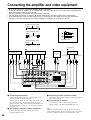
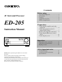
Contents
Before using
Important Safeguards ........................... 2
Precautions ........................................... 3
Features ................................................ 4
Supplied accessories ............................ 4
Before using this unit ........................... 5
AV Surround Processor
ED-205
Preparation
Connecting the amplifier and video
equipment ........................................... 6
Connecting equipment with 5.1channel audio output .......................... 7
Speaker placement and connection ...... 8
Connecting the z remote control
cables................................................ 10
Connecting the power ........................ 10
Instruction Manual
MASTER VOLUME
AV SURROUND PROCESSOR
EFFECT
MODE
Operation
STANDBY/ON
STANDBY
POWER
ON
MULTICHINPUT LINE
VIDEO-1/2
OFF
ED-205
Using the remote controller ............... 11
Using the Surround modes ................. 12
Playing a source ................................. 14
A few important notes
Thank you for purchasing the ONKYO AV Surround
Processor.
Please read this manual thoroughly before making
connections and turning on the power.
Following the instructions in this manual will enable you
to obtain optimum performance and listening enjoyment
from your new AV Surround Processor.
Please retain this manual for future reference.
Troubleshooting ................................. 17
Control positions and names .............. 18
Specifications ..................................... 20
WARNING:
TO REDUCE THE RISK OF FIRE OR ELECTRIC SHOCK,
DO NOT EXPOSE THIS APPLIANCE TO RAIN OR
MOISTURE.
CAUTION:
TO REDUCE THE RISK OF ELECTRIC SHOCK, DO NOT
REMOVE COVER (OR BACK). NO USER-SERVICEABLE
PARTS INSIDE. REFER SERVICING TO QUALIFIED
SERVICE PERSONNEL.
WARNING
AVIS
RISK OF ELECTRIC SHOCK
DO NOT OPEN
RISQUE DE CHOC ELECTRIQUE
NE PAS OUVRIR
The lightning flash with arrowhead symbol, within an equilateral
triangle, is intended to alert the user to the presence of uninsulated
“dangerous voltage” within the product’s enclosure that may be of
sufficient magnitude to constitute a risk of electric shock to persons.
The exclamation point within an equilateral triangle is intended to alert
the user to the presence of important operating and maintenance
(servicing) instructions in the literature accompanying the appliance.
Important Safeguards
1. Read Instructions – All the safety and operating
instructions should be read before the appliance is operated.
2. Retain Instructions – The safety and operating instructions
should be retained for future reference.
3. Heed Warnings – All warnings on the appliance and in the
operating instructions should be adhered to.
4. Follow Instructions – All operating and use instructions
should be followed.
5. Water and Moisture – The appliance should not be used
near water – for example, near a bathtub, washbowl, kitchen
sink, laundry tub, in a wet basement, or near a swimming
pool, and the like.
6. Carts and Stands – The appliance should be used only with
a cart or stand that is
PORTABLE CART WARNING
recommended by the
manufacturer.
6A.An appliance and cart
combination should be
moved with care. Quick
stops, excessive force, and
uneven surfaces may cause
the appliance and cart
S3125A
combination to overturn.
7. Wall or Ceiling Mounting – The appliance should be
mounted to a wall or ceiling only as recommended by the
manufacturer.
8. Ventilation – The appliance should be situated so that its
location or position does not interfere with its proper
ventilation. For example, the appliance should not be
situated on a bed, sofa, rug, or similar surface that may
block the ventilation openings; or if placed in a built-in
installation, such as a bookcase or cabinet that may impede
the flow of air through the ventilation openings, there should
be free space of at least 20 cm (8 in.) and an opening behind
the appliance.
9. Heat – The appliance should be situated away from heat
sources such as radiators, heat registers, stoves, or other
appliances (including amplifiers) that produce heat.
10. Power Sources – The appliance should be connected to a
power supply only of the type described in the operating
instructions or as marked on the appliance.
11. Polarization – If the appliance is provided with a polarized
plug having one blade wider than the other, please read the
following information:
The polarization of the plug is a safety feature. The
polarized plug will only fit the outlet one way. If the plug
does not fit fully into the outlet, try reversing it. If there is
still trouble, the user should seek the services of a qualified
electrician. Under no circumstances should the user attempt
to defeat the polarization of the plug.
12. Power-Cord Protection – Power-supply cords should be
routed so that they are not likely to be walked on or pinched
by items placed upon or against them, especially near plugs,
convenience receptacles, and the point where they exit from
the appliance.
13. Cleaning – The appliance should be cleaned only as
recommended by the manufacturer.
2
14. Nonuse Periods – The power cord of the appliance should
be unplugged from the outlet when left unused for a long
period of time.
15. Object and Liquid Entry – Care should be taken so that
objects do not fall and liquids are not spilled into the
enclosure through openings.
16. Damage Requiring Service – The appliance should be
serviced by qualified service personnel when:
A. The power–supply cord or the plug has been damaged; or
B. Objects have fallen, or liquid has been spilled into the
appliance; or
C. The appliance has been exposed to rain; or
D. The appliance does not appear to operate normally or
exhibits a marked change in performance; or
E. The appliance has been dropped, or the enclosure
damaged.
17. Servicing – The user should not attempt to service the
appliance beyond that described in the operating
instructions. All other servicing should be referred to
qualified service personnel.
Precautions
1. Warranty Claim
You can find the serial number on the rear panel of this unit. In
case of warranty claim, please report this number.
2. Recording Copyright
Recording of copyrighted material for other than personal use is
illegal without permission of the copyright holder.
3. AC Fuse
The fuse is located inside the chassis and is not user-serviceable.
If power does not come on, contact your Onkyo authorized
service station.
4. Care
From time to time you should wipe the front and rear panels and
the cabinet with a soft cloth. For heavier dirt, dampen a soft
cloth in a weak solution of mild detergent and water, wring it
out dry, and wipe off the dirt. Following this, dry immediately
with a clean cloth. Do not use rough material, thinners, alcohol
or other chemical solvents or cloths since these could damage
the finish or remove the panel lettering.
5. Power
WARNING
BEFORE PLUGGING IN THE UNIT FOR THE FIRST TIME,
READ THE FOLLOWING SECTION CAREFULLY.
The voltage of the available power supply differs according to
country or region. Be sure that the power supply voltage of the
area where this unit will be used meets the required voltage
(e.g., AC 230 V, 50 Hz or AC 120 V, 60 Hz) written on the rear
panel.
For British model
Replacement and mounting of an AC plug on the power supply
cord of this unit should be performed only by qualified service
personnel.
IMPORTANT
The wires in the mains lead are coloured in accordance with the
following code:
Blue : Neutral
Brown : Live
As the colours of the wires in the mains lead of this apparatus
may not correspond with the coloured markings identifying the
terminals in your plug, proceed as follows:
The wire which is coloured blue must be connected to the
terminal which is marked with the letter N or coloured black.
The wire which is coloured brown must be connected to the
terminal which is marked with the letter L or coloured red.
IMPORTANT
A 5 amp fuse is fitted in this plug. Should the fuse need to be
replaced, please ensure that the replacement fuse has a rating of
5 amps and that it is approved by ASTA or BSI to BS1362.
Check for the ASTA mark or the BSI mark on the body of the
fuse.
IF THE FITTED MOULDED PLUG IS UNSUITABLE FOR
THE SOCKET OUTLET IN YOUR HOME THEN THE FUSE
SHOULD BE REMOVED AND THE PLUG CUT OFF AND
DISPOSED OF SAFELY. THERE IS A DANGER OF
SEVERE ELECTRICAL SHOCK IF THE CUT OFF PLUG IS
INSERTED INTO ANY 13 AMP SOCKET.
If in any doubt, please consult a qualified electrician.
For U.S. model
Note to CATV system installer:
This reminder is provided to call the CATV system installer’s
attention to Article 820-40 of the NEC, ANSI/NFPA 70, which
provides guidelines for proper grounding and, in particular,
specifies that the cable ground shall be connected to the
grounding system of the building, as close to the point of cable
entry as practical.
FCC Information for User
CAUTION:
The user changes or modifications not expressly approved by
the party responsible for compliance could void the user’s
authority to operate the equipment.
NOTE:
This equipment has been tested and found to comply with the
limits for a Class B digital device, pursuant to Part 15 of the
FCC Rules. These limits are designed to provide reasonable
protection against harmful interference in a residential
installation. This equipment generates, uses and can radiate
radio frequency energy and, if not installed and used in
accordance with the instructions, may cause harmful
interference to radio communications. However, there is no
guarantee that interference will not occur in a particular
installation. If this equipment does cause harmful interference to
radio or television reception, which can be determined by
turning the equipment off and on, the user is encouraged to try
to correct the interference by one or more of the following
measures:
• Reorient or relocate the receiving antenna.
• Increase the separation between the equipment and receiver.
• Connect the equipment into an outlet on a circuit different
from that to which the receiver is connected.
• Consult the dealer or an experienced radio/TV technician for
help.
For Canadian model
CAUTION: THIS DIGITAL APPARATUS DOES NOT
EXCEED THE CLASS B LIMITS FOR RADIO NOISE
EMISSION FROM DIGITAL APPARATUS SET OUT IN THE
RADIO INTERFERENCE REGULATIONS OF THE
CANADIAN DEPARTMENT OF COMMUNICATIONS.
For models having a power cord with a polarized plug:
CAUTION: TO PREVENT ELECTRIC SHOCK, MATCH
WIDE BLADE OF PLUG TO WIDE SLOT, FULLY INSERT.
Modele pour les Canadien
ATTENTION: L’INTERFERENCE RADIO ELECTRIQUE
GENEREE PAR CET APPAREIL NUMERIQUE DE TYPE B
NE DEPASSE PAS LES LIMITES ENONCEES DANS LE
REGLEMENT SUR LES PERTURBATIONS RADIO
ELECTRIQUES, SECTION APPAREIL NUMERIQUE, DU
MINISTERE DES COMMUNICATIONS.
Sur les modeles dont la fiche est polarisee:
ATTENTION: POUR EVITER LES CHOCS
ELECTRIQUES, INTRODUIRE LA LAME LA PLUS LARGE
DE LA FICHE DANS LA BORNE CORRESPONDANTE DE
LA PRISE ET POUSSER JUSQU’AU FOND.
Declaration of Conformity
We, ONKYO EUROPE
ELECTRONICS GmbH
INDUSTRIESTRASSE 20
82110 GERMERING,
GERMANY
declare in own responsibility, that the ONKYO product described
in this instruction manual is in compliance with the corresponding
technical standards such as EN55013, EN55020, EN61000-3-2, -3-3
(or EN60555-2, -3) and EN60065
GERMERING, GERMANY
K.OTSU
ONKYO EUROPE ELECTRONICS GmbH
3
Features
Supplied accessories
Check that the following accessories are
supplied with your ED-205.
■ Compact, high-quality component design
■ Dolby* Pro Logic decoder with 3 surround
modes (Hall, Live, and Arena) and Stereo
mode
■ Superb expandability with 5.1-channel input
•
Audio connection cable ✕ 2
■ Flexible connectivity with Separate Collection
Series components
■ S-video connector
■ System control with supplied remote
controller
* Manufactured under license from Dolby Laboratories.
“Dolby”, “Pro Logic” and the double-D symbol
are trademarks
of Dolby Laboratories. Confidential Unpublished Works. ©19921997 Dolby Laboratories, Inc. All rights reserved.
• z cable ✕ 1
• Remote controller ✕ 1
Batteries (size AA, R6, or UM-3) ✕ 2
Memory Preservation
This unit does not require memory preservation batteries. A
built-in memory power back-up system preserves the
contents of the memory during power failures and even when
the unit is unplugged. The unit must be plugged in order to
charge the back-up system.
The memory preservation period after the unit has been
unplugged varies depending on climate and placement of the
unit. On the average, memory contents are protected over a
period of a few weeks after the last time the unit has been
unplugged. This period is shorter when the unit is exposed to
a highly humid climate.
4
Before operating this unit
1
Installing the remote controller batteries
1 Remove the battery compartment cover by pressing the tab
and lifting up the cover.
2 Insert two AA (R6- or UM-3)-size batteries into the battery
compartment. Carefully follow the polarity diagram (positive
(+) and negative (-) symbols) inside the battery compartment.
3 After batteries are installed and seated correctly, replace the
compartment cover.
2
Notes:
• Do not mix new batteries with old batteries or different kinds
of batteries.
• To avoid corrosion, remove the batteries if the remote
controller is not to be used for a long time.
• Remove dead batteries immediately to avoid damage from
corrosion. If the remote controller doesn’t operate smoothly,
replace both the batteries at the same time.
• The life of the batteries supplied is about six months but this
will vary depending on usage.
3
Using the remote controller
Point the remote controller toward the remote control sensor.
Remote control
sensor
ED-205
Amplifier
30°
30°
5m
Notes:
• Place the unit away from strong light such as direct sunlight
or inverted fluorescent light which can prevent proper
operation of the remote controller.
• Using another remote controller of the same type in the same
room or using the unit near equipment which uses infrared
rays may cause operational interference.
• Do not put any object such as a book on the remote controller.
The buttons of the remote controller may be pressed by
mistake and drain the batteries.
• Make sure the audio rack doors do not have colored glass.
Placing the unit behind such doors may prevent proper remote
controller operation.
• If there is any obstacle between the remote controller and the
remote control sensor, the remote controller will not operate.
5
Connecting the amplifier and video equipment
• Do not connect the power cord until you complete all other connections.
• Connect the unit to your amplifier via the supplied audio connection cables. Be sure to insert the cable's red plugs into the
Right jacks and white plugs into the Left jacks.
For other connections, use the cables that came with that equipment.
• Insert the plugs and connectors completely. Remember that improper connection results in noise or malfunction.
• Do not bind the audio connection cables with the power cord and speaker cables. Doing so may degrade sound quality.
• The unit’s cover will become hot due to its built-in amplifier. Avoid placing any equipment on the unit.
S-Video connection cable
S-Video
S-Video
Improper connection
Audio connection cable
L (left)
L
R (right)
R
Insert completely
Video connection cable
(Yellow)
V (video)
V
:Signal flow
2
3
Video disc player,
BS tuner, etc.
Output
4
1
Amplifier
(Such as A-905)
Video cassette recorder
Monitor
TV
Output
Input
Output
S VIDEO
VIDEO
Input
SUB WOOFER
PRE OUT
CENTER
IN
VIDEO-1
OUT
IN
VIDEO-2
IN
MONITOR
VIDEO-1
OUT
OUT
IN
VIDEO-2
Input
Input
(PROCESSOR
IN)
Output
(PROCESSOR
OUT)
REMOTE
CONTROL
R
SURROUND
L
MONITOR OUT
CENTER
L
CAUTION:
SPEAKER
R
IN
VIDEO-1
OUT
IN
VIDEO-2
IN
OUT
PROCESSOR
FRONT SURROUND
1 Connecting the amplifier
Connect the amplifier's processor connection jacks to the
ED-205's PROCESSOR IN/OUT jacks.
With an Onkyo amplifier such as A-905 , remove the jumper
plug in the processor jack before connecting the audio
connection cables. The removed jumper plug should be kept
for future use. Never attempt to insert the jumper plug into
any other jacks.
2 Connecting a video disc player or BS tuner
Connect the equipment's Video output jacks to the
ED-205's VIDEO-1 jacks.
6
SUBWOOFER
MULTI
CHANNEL INPUT
SPEAKERS
IMPEDANCE
6 OHMS MIN.
/SPEAKER
3 Connecting a video cassette recorder
Connect the video cassette recorder's Video jacks to the ED205's VIDEO-2 jacks.
4 Connecting a TV monitor
Connect the TV monitor's Video input jack to the
ED-205's Video or S VIDEO MONITOR OUT jack.
Note:
This unit's S VIDEO IN/OUT jacks do not have an S-Video/
Video switching feature. Be sure to connect your video cassette
recorder via either the Video or S-Video connection cable.
Connecting equipment with 5.1-channel
audio output
Connecting equipment with 5.1-channel audio output (such as a DVD player)
Connect the equipment's 5.1-channel output jacks to the ED-205's MULTI CHANNEL INPUT jacks.
The equipment's 2-channel audio output jacks should be connected to the amplifier such as A-905 's LINE-1 jacks.
The equipment's Video output jack should be connected to the ED-205's VIDEO-1 IN jack.
2-ch audio
output
Video
output
5.1-ch audio output
Front
Surround
Center
Subwoofer
To Amplifier
:Signal flow
S VIDEO
VIDEO
SUB WOOFER
PRE OUT
CENTER
IN
VIDEO-1
OUT
IN
VIDEO-2
IN
MONITOR
VIDEO-1
OUT
OUT
IN
VIDEO-2
REMOTE
CONTROL
R
SURROUND
L
MONITOR OUT
CENTER
L
CAUTION:
SPEAKER
R
IN
VIDEO-1
OUT
IN
VIDEO-2
IN
OUT
PROCESSOR
FRONT SURROUND
SUBWOOFER
MULTI
CHANNEL INPUT
SPEAKERS
IMPEDANCE
6 OHMS MIN.
/SPEAKER
7
Speaker placement and connection
The unit is equipped with speaker terminals for connecting the
Center speaker and Surround speakers, in addition to the
SUBWOOFER PRE OUT jack to allow connection to your
Subwoofer.
Use the ED-205's SUBWOOFER PRE OUT jack to connect
your Subwoofer, even if your amplifier also has a subwoofer
connection jack.
Connect the Left and Right front speakers to your amplifier's
speaker terminals.
Speaker placement
TV/Screen
テレビ/スクリーン
Left Front SubCenter
サブ センター
左フロント
speakerウーファー
woofer スピーカー
speaker
スピーカー
Right Front
右フロント
speaker
スピーカー
In this section, only one example of possible speaker placement
is shown. Note, however, that ideal speaker placement varies
depending on the size of the room and the wall coverings used
in the room. To obtain ideal sound field effects, the Left and
Right front speakers must be placed at equal distances from the
listening position.
Important Points
Left
Surround
左サラウンド
speaker
スピーカー
Right
Surround
右サラウンド
speaker
スピーカー
視聴位置
Listening
position
1
2
15mm
3
4
5
Notes:
8
• Left and Right front speakers (L/R) and Center
speaker (C)
Place these three speakers at the same height from the floor.
Place each speaker so that sound is aimed at the audience's
ears at the listening position.
• Left and Right Surround speakers (LS/RS)
Place these speakers so that their height is 1 meter (3 feet)
higher than that of the audience's ears.
• Subwoofer (SW)
Place it anywhere in your listening room that produces
satisfactory sound. The placement of the Subwoofer affects
the perceived direction of the sound very little, but optimal
bass reproduction will be achieved with placement in a
corner.
If your speaker system lacks Subwoofer, Center
speaker, or Surround speakers
To get the highest-quality surround sound from the ED-205, you
need a complete set of 6 speakers. However, you can enjoy
quality surround sound by setting the ED-205 to properly
distribute the sound originally intended for these non-existing
speakers to existing front and surround speakers, even if your
system lacks the subwoofer, center speaker, or surround
speakers.
Connecting the speaker cables
1 Peel the insulation off the ends of the speaker cable 15 mm.
Do not cut core wires.
2 Twist the core wires.
3 Press the lever below the speaker terminal to open the
connection hole.
4 Insert the core wires into connection hole.
5 Return the lever to the original position.Make sure that the
core wires are barely visible where they enter the connection
hole.
Notes:
• Be sure to connect the Right and Left speakers to the unit's
corresponding speaker terminals. Also, be sure that you are
connecting the speaker's positive (+) and negative (-) binding
posts with unit's corresponding speaker terminals. Otherwise,
inferior sound will result.
• Use speakers whose nominal impedance is 6 to 16Ω.
Connecting a speaker whose impedance is lower than 6Ω may
cause damage to the unit.
• Do not connect two or more speaker cables to the same
speaker terminal. Doing so may cause damage to the unit.
• To prevent damage to the circuitry, never short-circuit the
positive (+) and negative (-) speaker wires by allowing them
to touch each other.
Speaker placement and connection
• Follow the diagram below to connect each speaker as illustrated, observing the correct connections for R, L, + and -.
• Do not use unnecessarily long or extremely thin speaker cables.If the DC resistance of the speaker cables is too high, the
damping factor will decrease, adversely affecting the sound quality.
Speaker Impedance
This unit is designed to produce optimum sound quality when spakers with impedances within the specified ranges are connected.
Please check the following information and choose speakers with the necessary impedances for the connections.
CENTER SPEAKER
: 6 ohms mim.
SURROUND SPEAKERS : 6 ohms mim./speaker
1 Center speaker
Right Front speaker
3 Subwoofer
Left Front speaker
Amplifier
L
SUB WOOFER
PRE OUT
R
CENTER
REMOTE
CONTROL
R
SURROUND
L
ED-205
2 Right Surround
speaker
S VIDEO
VIDEO
SUB WOOFER
PRE OUT
CENTER
IN
VIDEO-1
OUT
IN
VIDEO-2
IN
VIDEO-1
OUT
IN
VIDEO-2
IN
MONITOR
VIDEO-1
OUT
OUT
IN
VIDEO-2
2 Left Surround
speaker
REMOTE
CONTROL
R
SURROUND
L
MONITOR OUT
CENTER
L
CAUTION:
SPEAKER
R
IN
OUT
PROCESSOR
SPEAKERS
IMPEDANCE
6 OHMS MIN.
SUB/SPEAKER
WOOFER
MULTI
CHANNEL INPUT
FRONT SURROUND
CAUTION:
SPEAKER
SPEAKERS
IMPEDANCE
6 OHMS MIN.
/SPEAKER
1 Connecting the Center speaker
Subwoofer
2 Connecting the Surround speakers
Amplifier
3 Connecting the Subwoofer
ED-205
S VIDEO
VIDEO
SUB WOOFER
PRE OUT
CENTER
IN
VIDEO-1
OUT
IN
VIDEO-2
IN
VIDEO-1
OUT
IN
VIDEO-2
IN
MONITOR
VIDEO-1
OUT
OUT
IN
VIDEO-2
REMOTE
CONTROL
R
SURROUND
L
MONITOR OUT
CENTER
L
CAUTION:
SPEAKER
R
IN
OUT
PROCESSOR
SPEAKERS
SUB WOOFER
PRE OUT
IMPEDANCE
6 OHMS MIN.
SUB/SPEAKER
WOOFER
MULTI
CHANNEL INPUT
REMOTE
CONTROL
FRONT SURROUND
CENTER
CAUTION:
SPEAKER
IMPEDANCE
6 OHMS MIN.
/SPEAKER
R
SURROUND
L
SPEAKERS
Connect your subwoofer to the ED-205's SUBWOOFER PRE
OUT jack via an audio connection cable.
• From the SUBWOOFER PRE OUT jack, a monaural signal
that is a mixture of the Left and Right channel signals is
output.
• Use the ED-205's SUB WOOFER PRE OUT jack to connect
your Subwoofer, even if your amplifier also provides a
subwoofer connection jack.
• If your subwoofer does not have a built-in amplifier, connect
an amplifier to the SUBWOOFER PRE OUT jack and the
subwoofer to that amplifier.
9
Connecting the z cables
If your system is totally configured with ONKYO separate
collection series components, you can use the system functions
using the ED-205's supplied remote controller.
Connect all components in series using the z cables, starting
with the amplifier. For components having two z REMOTE
CONTROL jacks, you may use either of them because their
functions are same.
• If your system already has been set up with the ONKYO
separate collection series components, connect the ED-205's
z REMOTE CONTROL jack to the CD player's or tuner's
unused z REMOTE CONTROL jack.
• To operate the system components, point the remote
controller toward the amplifier's remote control sensor.
• To operate the ED-205, point the remote controller toward the
ED-205's remote control sensor.
Notes:
• Do not use the z REMOTE CONTROL jack to connect
products not bearing the z symbol. Doing so may result in
the damage to the equipment.
• Connecting only the z cables is not sufficient for operation
of your system. Connect the components also via audio
connection cables.
• Connect the speaker cables before you connect the z cables.
ED-205
MASTER VOLUME
AV SURROUND PROCESSOR
EFFECT
MODE
STANDBY/ON
STANDBY
POWER
ON
MULTICHINPUT LINE
VIDEO-1/2
OFF
ED-205
T-405R(Tuner)
A-909/A-909 LTD/A-905(Amplifer)
MD-105(MD Recorder)
C-705/C-705 LTD(CD Player)
Connecting the power
Before plugging in the unit, confirm that all connections have
been made properly.
Turning on this unit’s power may cause a momentary power
surge, which might interfere with other electrical equipment,
such as computers. If so, use a wall outlet on a different circuit.
STANDBY indicator
STANDBY/ON button
MASTER VOLUME
AV SURROUND PROCESSOR
EFFECT
MODE
STANDBY/ON
STANDBY
POWER
ON
MULTICHINPUT LINE
VIDEO-1/2
OFF
ED-205
POWER switch
10
After plugging the ED-205’s power cord into an AC outlet, press
the POWER switch to put the unit in power-standby status (the
SATNDBY indicator is lit). The remote controller cannot be used
to operate the ED-205 if the POWER switch is not set ON.
When the POWER switch is set ON, pressing the STANDBY/
ON button or the POWER button on the remote controller
switches the ED-205 between standby status (the STANDBY
indicator is lit) and power on status (the display is lit).
Press the POWER switch on the ED-205 to set it to the OFF
position, turning of the unit.
Using the remote controller
Buttons that become operative once the z
remote control cables are connected
(See page 10 for how to connect the z
cables.)
1 Amplifier operation buttons
1
POWER
SLEEP
PRESET
LINE-1
TUNER
FM
LINE-2
AM
4
5
DVD
2 MD recorder operation buttons
2
MD
3
TAPE
DISC
6
CD
EFFECT MULTI CH
Point the remote controller toward the amplifier’s remote
control sensor.
POWER
: Turns the power on or off.
SLEEP
: Sets the time (in units of10 minutes) until the
power is automatically shut off. Setting range:
90 to 10 minutes
LINE-1
: Selects the component connected to the
amplifier's LINE-1 jack.
LINE-2
: Selects the component connected to the
amplifier's LINE-2 jack.
LINE
VIDEO
MODE
CH SEL
LEVEL
DELAY
TIME
TEST
TONE
VOLUME
CENTER
MODE
MUTING
RC-394S
REMOTE CONTROLLER
*
Point the remote controller toward the MD recorder’s remote
control sensor.
q
: Jumps to the beginning of the current track
(when playing) or previous track (when
stopped).
w
: Jumps to the beginning of the next track.
e
: Stops playing the MD.
s
: Plays the MD.
3 Tapedeck operation buttons
Point the remote controller toward the amplifier’s remote
control sensor.
d
: Fast-rewinds the tape.
f
: Fast-forwards the tape.
a
: Plays the reverse side of the tape.
s
: Plays the tape.
e
: Stops playing, recording, or fast-forwarding.
4 Tuner operation buttons
Point the remote controller toward the amplifier’s remote
control sensor.
aPRESETs : Selects preset radio stations.
FM
: Selects FM broadcasts.
AM
: Selects AM broadcasts.
5 DVD player operation buttons
Point the remote controller toward the DVD player’s remote
control sensor.
q
: Jumps to the beginning of the current chapter
or track (when playing) or previous chapter or
track (when stopped).
w
: Jumps to the beginning of the next chapter or
track.
e
: Stops playing the DVD.
s
: Plays the DVD.
6 CD player operation buttons
Point the remote controller toward the amplifier’s remote
control sensor.
d f : Fast-returns or fast-forwards the CD.
DISC
: Selects the disc to play (when using a CD
changer).
q w : Jumps to the beginning of the current track
(when playing), the previous track (when
stopped), or the next track.
e
: Stops playing the CD.
s
: Plays the CD.
* The operation buttons for the ED-205 are explained on page
12 and later. (Point the remote controller toward the ED-205’s
remote control sensor.)
11
Using the Surround Modes
• LIVE Surround
Using the Surround Modes
This mode reproduces the feel of a live performance.
This unit provides a variety of surround effects, enabling you to
enjoy the feeling of a movie theater, concert hall, or studio in
your room.
To get optimized surround sounds, your speaker system plays an
important role. For how to connect and setup speakers, see
pages 8 and 9.
• DOLBY PRO LOGIC Surround
• ARENA Surround
This mode recreates the feel of listening to a pop concert in a
domed stadium.
For speaker systems with only Left front, Right
front, and Center speakers
• DOLBY 3 STEREO
Use this mode to playback sources bearing
logo, such as VHS Hi-Fi, laser discs, and DVD video software.
Dolby Pro Logic Surround provides four channels of surround
sound (Left/Right front, Center, and monaural Surround
channels), with emphasis placed on the Center speaker.
• HALL Surround
In this mode, you can hear the sound recorded for surround
channels from the Left and Right speakers.
• STEREO
You can turn off the Surround function by selecting this mode to
enjoy ordinary stereo sound.
This mode is especially suitable for media already having a
substantial amount of reverberation such as classical music. The
atmosphere of a concert hall can be simulated.
POWER
SLEEP
1
PRESET
LINE-1
TUNER
FM
LINE-2
AM
DVD
1
4
3
2
MD
TAPE
DISC
MASTER VOLUME
AV SURROUND PROCESSOR
CD
EFFECT
MODE
4
STANDBY/ON
STANDBY
MULTICHINPUT LINE
POWER
ON
VIDEO-1/2
OFF
ED-205
5
6
EFFECT MULTI CH
LINE
VIDEO
MODE
CH SEL
LEVEL
DELAY
TIME
TEST
TONE
VOLUME
CENTER
MODE
MUTING
2
7123
3
RC-394S
REMOTE CONTROLLER
1
Before enjoying Surround Play
(Front panel)
(Remote controller)
POWER
STANDBY/ON
2
3
LINE
VIDEO-1/2
LINE
MASTER VOLUME
VIDEO
VOLUME
4
MODE
MODE
The mode changes as shown below each time the MODE a or s
button is pressed
(Only the s button is available with the remote controller.)
DOLBY PRO LOGIC
ARENA
12
DOLBY 3 STEREO
LIVE
HALL
Before you can enjoy Surround Play with the ED-205, the
following settings are necessary according to the configuration
and placement of your speakers. Once set, the settings can be
used until you alter the configuration or placement of the
speakers.
Set the amplifier's volume control to a comfortable level at your
normal listening position.
1. Press the POWER button.
The STANDBY indicator goes out and the display lights up.
2. Select the input source.
LINE: Press this button to play the source selected on the
amplifier that is connected to the unit’s PROCESSOR jacks.
VIDEO 1/2: Press this button to play the video source
connected to the unit’s VIDEO-1 or VIDEO-2 jacks.
3. Play Dolby Surround encoded software and adjust the
sound volume.
The sound volume for all speakers simultaneously changes.
4. Press the MODE button to select
“DOLBY PRO LOGIC” or “DOLBY 3 STEREO”.
DOLBY PRO LOGIC: Select this mode if your system
includes all of the Left/Right front, Center, and Surround
speakers.
DOLBY 3 STEREO: Select this mode if your system lacks
the Surround speakers.
Note:
• You cannot select “DOLBY 3 STEREO” when the
CENTER mode setting is “PHANTOM”.
• When you have selected “DOLBY 3 STEREO” in this step,
the steps 5 and 6 are unnecessary. Proceed to step 7.
Using the Surround modes
5
(Remote controller)
CENTER
MODE
6
DELAY
TIME
71
TEST
TONE
2
CH SEL
LEVEL
5. Press the CENTER MODE button on the remote
controller to select “NORMAL” or “PHANTOM”.
NORMAL: Select this mode if your system includes the
Center speaker.
PHANTOM: Select this mode if your system lacks the
Center speaker. In this mode, you can hear the sound
originally allocated to the Center channel from the Left and
Right front speakers. Without the Center speaker, place the
front speakers as close to the monitor TV as possible, making
sure that the screen color on the monitor TV is not affected.
6. Set the proper delay time for your listening position and
speaker placement (using the remote controller).
The possible delay time settings are 15, 20, 25 or 30 ms.
(For details, see “Setting the delay time” below.)
7. Adjust the output level of center speaker and surround
speaker channel so that you hear the same sound volume
from each speaker at the listening position(using the
remote controller).
You cannot change the output levels of the Left and Right
front speakers. While listening to the test tone, adjust the
output levels of other speakers.
This adjustment is normally made from the listening position
using the remote controller.
1 Press the TEST TONE button.
The test tone starts sounding at the Left front speakers.
After 2 seconds, the test tone sounds at the next speaker.
• When the Center Mode setting is “NORMAL”
Left Front (TEST L)
Center (TEST C)
Left Surround (TEST LS)
Right Front (TEST R)
Right Surround (TEST RS)
• When the Center Mode setting is “PHANTOM”
Left Front (TEST L)
Left Surround (TEST LS)
Right Front (TEST R)
Right Surround (TEST RS)
• When the Surround Mode setting is “DOLBY 3 STEREO”
Left Front (TEST L)
3
Center
センター
speaker
スピーカー
Right front
右フロント
speaker
スピーカー
Setting the delay time
“Delay time” is set according to the distance from the Center
and Surround Speakers to the listening position.
• In the DOLBY PRO LOGIC mode
L1(m)
L1(m)
L2(m)
L2(m)
鑑賞位置
Listening
position
左サラウンド
Left
Surround
スピーカー
speaker
Right Front (TEST R)
2 Adjust the output level using the LEVEL y/u buttons.
The adjustment range is -12dB to +12dB.
The test tone stays at the same speaker while the
adjustment is in progress.
You can select the speaker channel to adjust by using the
CH SEL button on the remote controller.
3 Press the TEST TONE button again.
The test tone stops sounding.
TEST
TONE
Left front
左フロント
speaker
スピーカー
Center (TEST C)
右サラウンド
Right
Surround
スピーカー
speaker
L1 - L2
Recommended delay time
Below 1 m
15 ms
1 to 2.5 m
20 ms
2.5 to 4 m
25 ms
Over 4 m
30 ms
Note: 1 ms = 1/1000 second (one millisecond)
Set the proper delay time for your listening position and speaker
placement.
Measure the distance from your listening position to the Center
speaker (L1) and to the Surround speakers (L2). Then, choose
the correct delay time in the table below according to the
difference between L1 and L2.
Ex.
Assume, in the figure on the left, that the distance from the Center
speaker to your listening position (L1) is 2 meters and the distance
from the Surround speakers to your listening position (L2) is 3.5
meters. Since the difference between L1 and L2 is 1.5 meters, the
table indicates that the correct delay time is 20 ms.
• In the HALL, LIVE, or ARENA mode
Set the delay time according to your taste while listening to the
sound. The possible delay time settings are 15, 20, 25, 30, 40,
50 or 60 ms.
13
Playing a source
If you wish to adjust the sound volume of the Right or Left front speaker, always use the ED-205's MASTER VOLUME knob with the
amplifier's volume control at the Surround setting position as explained on pages 12 and 13. The output levels of the Center and
Surround speakers must be readjusted every time you alter the amplifier's volume control setting.
a MODE s
STANDBY/ON
MASTER
VOLUME
POWER
POWER
SLEEP
PRESET
LINE-1
TUNER
FM
LINE-2
AM
DVD
MD
TAPE
MASTER VOLUME
AV SURROUND PROCESSOR
DISC
EFFECT
LINE
MODE
CD
EFFECT
STANDBY/ON
STANDBY
MULTICHINPUT LINE
POWER
ON
MODE
VIDEO-1/2
DELAY
TIME
OFF
ED-205
EFFECT MULTI CH
LINE
VIDEO
MODE
CH SEL
LEVEL
DELAY
TIME
TEST
TONE
VOLUME
CENTER
MODE
MUTING
VIDEO
CH SEL
u LEVEL y
VOLUME
RC-394S
REMOTE CONTROLLER
EFFECT
VIDEO-1/2
LINE
1
Playing a Dolby Pro Logic surround source
(Front panel)
(Remote controller)
POWER
STANDBY/ON
2
LINE
VIDEO-1/2
LINE
VIDEO
3
MODE
5
14
MASTER VOLUME
MODE
VOLUME
Before playing a Dolby Pro Logic surround source, the unit
must be set according to “Before enjoying Surround Play” on
pages 12 and 13.
1. Press the POWER button.
The STANDBY indicator goes out and the display lights up.
2. Select the input source.
LINE: Press this button to play the source selected on the
amplifier that is connected to the unit’s PROCESSOR jacks.
VIDEO 1/2: Press this button to play the video source
connected to the unit’s VIDEO-1 or VIDEO-2 jacks.
3. Press the MODE button to select “DOLBY PRO LOGIC”
or “DOLBY 3 STEREO”.
The mode changes as shown each time the MODE a or s
button is pressed (Only the s button is available with the
remote controller.)
4. Play a Dolby Pro Logic encoded source.
5. Adjust the sound volume.
The sound volume for all speakers simultaneously changes.
Adjust the sound volume from the listening position using the
remote controller.
* The sound volume for the Subwoofer can be adjusted by first
pressing the CH SEL button to select “SW” on the display and
then using the LEVEL y/u button.
If you wish to fine-adjust the sound volume for a channel
while listening to the sound, select that speaker on the display
in the same way and then adjust the sound volume.
Playing a source
3
5
(Front panel)
(Remote controller)
MODE
MODE
MASTER VOLUME
Before you enjoy HALL, LIVE, or ARENA surround mode, it is
recommended that the unit be set according to “Before enjoying
the Surround Play” on pages 12 and 13.
VOLUME
61
CH SEL
LEVEL
CH SEL
LEVEL
2
7
Playing in the HALL, LIVE, or ARENA surround
mode
DELAY
TIME
1. Same as step 1. of “Playing a Dolby Pro Logic surround
source”.
2. Same as step 2. of “Playing a Dolby Pro Logic surround
source”.
3. Press the MODE button to select “HALL” “LIVE”, or
“ARENA”.
The mode changes as shown below each time the MODE a
or s button is pressed
(Only the s button is available with the remote controller.)
4. Play a Dolby Pro Logic surround source.
5. Adjust the sound volume.
The sound volume for all speakers simultaneously changes.
Adjust the sound volume from the listening position using the
remote controller.
6. Adjust the output level of each speaker according to your
taste.
If you have selected “HALL” or “ARENA” in step 3, you can
adjust the output levels for the Right Surround speaker (RSUR), Left Surround speaker (L-SUR), and Subwoofer (SW).
If you have selected “LIVE” in step 3, you can adjust the
output levels for the Center speaker (CENTER), Right
Surround speaker (R-SUR), Left Surround speaker (L-SUR),
and Subwoofer (SW).
1 Select the speaker channel to adjust by using the CH
SEL button on the remote controller.
2 Adjust the output level using the LEVEL y/u
buttons.
The adjustment range is -12dB to +12dB.
Note:
The output levels you set in this step will be lost if the
ED-205 is turned off.
7. Set the proper delay time for your listening position and
speaker placement.
The possible delay time settings are 15, 20, 25, 30, 40, 50 or
60 ms. (For details, see “Setting the delay time” on page 13.)
3
5
(Front panel)
EFFECT
MASTER VOLUME
(Remote controller)
EFFECT
VOLUME
Playing in the Stereo mode
1. Same as step 1. of “Playing a Dolby Pro Logic surround
source”.
2. Same as step 2. of “Playing a Dolby Pro Logic surround
source”.
3. Press the EFFECT button to select “STEREO”.
4. Play a source.
5. Adjust the sound volume.
The sound volume for all speakers simultaneously changes.
Adjust the sound volume from the listening position using the
remote controller.
15
Playing a source
1
4
1
POWER
SLEEP
PRESET
LINE-1
TUNER
FM
LINE-2
AM
DVD
MD
MASTER VOLUME
AV SURROUND PROCESSOR
EFFECT
TAPE
MODE
DISC
STANDBY/ON
CD
STANDBY
EFFECT MULTI CH
MULTICHINPUT LINE
POWER
2
ON
LINE
VIDEO
VIDEO-1/2
MODE
CH SEL
LEVEL
DELAY
TIME
TEST
TONE
VOLUME
CENTER
MODE
MUTING
OFF
ED-205
512
4
2
RC-394S
REMOTE CONTROLLER
Playing a multi-channel input source
(Front panel)
1
POWER
STANDBY/ON
2
MULTI CH
MULTI CH INPUT
4
VOLUME
MASTER VOLUME
51
2
16
(Remote controller)
CH SEL
CH SEL
LEVEL
LEVEL
The following describes how to play a multi-channel input
source. A multi channel input source refers to equipment with
5.1-channel output jacks (such as a DVD player). When
connected to the ED-205, the equipment outputs separate signals
to the 5 speaker channels (Left/Right front, Center, and Left/
Right Surround). The ED-205 then outputs the signal for the
subwoofer channel to its SUBWOOFER PRE OUT jack. In the
Multi-channel input mode, you cannot use the surround modes.
For how to connect a multi-channel input source, see page 7.
Before playing a multi-channel input source
• The ED-205 stores the output level you set for each speaker
connected to the MULTI CHANNEL INPUT jack. This stored
setting has no effect on the DOLBY PRO LOGIC output levels
you set using- the test tone.
1. Press the POWER button.
The STANDBY indicator goes out and the display lights up.
2. Press the MULTI-CH INPUT button.
3. Play the input source connected to the MULTI CHANNEL
INPUT jacks.
4. Adjust the sound volume.
The sound volume for all speakers simultaneously changes.
Adjust the sound volume from the listening position using the
remote controller.
5. Adjust the output level of each speaker according to your
taste.
The output levels for the Center speaker (CENTER), Right
Surround speaker (R-SUR), Left Surround speaker (L-SUR),
and Subwoofer (SW) can be adjusted.
1 Select the speaker channel to adjust by using the CH
SEL button on the remote controller.
2 Adjust the output level using the LEVEL y/u
buttons.
The adjustment range for the Center, and Left/Right Surround
speakers is -12dB to +12dB. For the Subwoofer, it is -30 to
+12dB.
Troubleshooting
If you have any problems with the unit, please check the troubleshooting table below.
This unit contains a sensitive microcomputer, which under certain circumstances might fail to operate due to excessive noise
interference. In such an event, disconnect the main plug from the electrical outlet and reconnect it after 5 seconds. Please also ensure
that all system connections are correct and secure.
If the problem persists, or if the symptom is not found in the troubleshooting table, disconnect the power cord, and notify your Onkyo
service station. Include your name, address, and telephone number, as well as the product name, model number (ED-205), serial
number, and a detailed description of the problem.
Power
Symptom
The unit does not turn
on.
No image or sound.
Cause
• The power plug is not inserted
completely.
• The cables are not connected
securely.
• The cables are not connected
correctly.
• The input source equipment has
not been selected.
Speaker
No sound from front
speakers.
No sound or quiet sound
from Center speaker.
• The MASTER VOLUME knob on
the amplifier is set to the minimum.
• The Muting mode is set on the
amplifier.
• The audio connection cables and
speaker cables are not connected
properly.
• The STEREO mode is set.
• The output level is not adjusted
correctly.
• The Center mode is set to
“PHANTOM” when the Surround
mode is “DOLBY PRO LOGIC”.
• The Surround mode is set to
“HALL” or “ARENA”.
No sound or quiet sound
from Surround speakers.
• The STEREO mode is set.
• The output levels of the Surround
speakers are not adjusted
correctly.
• The Surround mode is set to
“DOLBY 3 STEREO”.
Others
No image on the TV
connected to the S VIDEO
MONITOR OUT jack.
No test tone sound.
Remote
controller
No image in Multi-channel
input mode.
Buttons on the front panel
are operational, but those
on remote controller are
not.
• The video source is connected to
the VIDEO IN jacks.
• The S-Video cables are not
connected completely.
• The Multi-channel input mode is
set.
• The multi-channel input source is
not connected correctly.
• The batteries are not installed
correctly.
• The batteries are run down.
Remedy
• Insert the unit’s power plug completely into
a power outlet. [See page 10.]
• Check again the connection and connect the
plugs and cables securely. [See pages 6 and
7.]
• Check that the video and audio cables are
connected correctly.
[See pages 6 and 7.]
• Check the input source connection and
select the correct input source by pressing
the correct input selector button (LINE,
VIDEO-1/2, MULTI-CH INPUT). [See
pages 14 to 16.]
• Set the sound volume properly.
[See pages 14 to 16.]
• Press the MUTING button on the amplifier
to cancel the Muting mode.
• Check the connection again and connect the
plugs and cables properly. [See page 6.]
• Press the EFFECT button to select a correct
Surround mode.
• Adjust the output level of the Center speaker
to the correct level.
[See pages 12 to 16.]
• Set the Center mode to “NORMAL”. [See
page 13.]
• Set the Surround mode to “DOLBY PRO
LOGIC”, “DOLBY 3 STEREO”, or
“LIVE”. [See pages 12 to 15.]
• Press the EFFECT button to select the
correct Surround mode.
• Adjust the output levels of the Surround
speakers to correct levels.
[See pages 12 to 16.]
• Press the MODE button to select “DOLBY
PRO LOGIC”, “HALL”, “LIVE”, or
“ARENA”. [See pages 12 to 15.]
• The signals input to the VIDEO IN jacks are
not output from the S VIDEO MONITOR
OUT jack. Connect the video source to the
S VIDEO IN jack or connect the TV to the
VIDEO MONITOR OUT jack.
[See page 6.]
• Connect the S-Video cables completely.
[See page 6.]
• The test tone does not sound when the
Multi-channel input mode is set.
[See pages 12 and 13.]
• Check the connection for the multi-channel
input source. [See page 7.]
• Insert the batteries correctly.
[See page 5.]
• Replace the batteries with new ones. [See
page 5.]
17
Control positions and names
In this section, the name of each switch or button that appears in the description of this manual is indicated. The function or description
of the switch or button name is also included when necessary. The numbers shown in each pair of brackets [ ] indicate the page
numbers of the manual in which the switch or button is explained.
Front panel
1
2
3
4
5
6
MASTER VOLUME
AV SURROUND PROCESSOR
EFFECT
MODE
STANDBY/ON
STANDBY
MULTICHINPUT LINE
POWER
POWER
ON
ON
VIDEO-1/2
OFF
OFF
ED-205
0
9
8 7
Display
1
2
3
4
5
SURROUND MODE
SW
INPUT SELECTOR
LINE
VIDEO-1
C
LS
RS
VIDEO-2
mS
dB
6
Front panel
1 STANDBY indicator [10]
2 STANDBY/ON button [10,12,14,16]
Power ON/Standby button
3 Remote control sensor [5]
4 EFFECT button [15]
Changes between Surround and Stereo modes.
5 MODE button [12,14,15]
Changes between all Surround modes.
6 MASTER VOLUME knob [12,14,15,16]
7 VIDEO-1/2 button [12,14]
Video input selector button
8 LINE button [12,14]
Line input selector button
9 MULTI CH INPUT button [16]
Multi-channel input selector button
0 POWER switch [10]
18
Display
1
2
3
4
5
6
INPUT SELECTOR indicator
SURROUND MODE indicator
CENTER MODE indicator
MUTING indicator
Speaker output level indicator
Multi-function display
Control positions and names
A
1
2
POWER
SLEEP
PRESET
LINE-1
TUNER
FM
LINE-2
B
AM
DVD
3
4
MD
5
TAPE
DISC
6
7
8
9
0
CD
EFFECT MULTI CH
LINE
VIDEO
MODE
CH SEL
LEVEL
DELAY
TIME
TEST
TONE
VOLUME
CENTER
MODE
MUTING
C
D
E
F
RC-394S
REMOTE CONTROLLER
G
H
Remote controller
When the unit is connected to Onkyo separate collection series
components (amplifier, tuner, DVD player, MD recorder,
cassette deck, and CD player), you can use the supplied remote
controller to operate each component (see page 11). The buttons
shown in shaded areas are those for operating components other
than the ED-205.
1 POWER button [11,12,14,16]
Turns on/off the amplifier or ED-205.
2 TUNER operation buttons [11]
3 DVD operation buttons [11]
4 MD operation buttons [11]
5 TAPE operation buttons [11]
6 CD operation buttons [11]
7 EFFECT button [15]
Changes between Surround and Stereo modes.
8 MODE button [12,14,15]
Changes between all Surround modes.
9 DELAY TIME button [13]
0 CENTER MODE button [13]
A SLEEP button [11]
B LINE-1 /LINE-2 buttons [11]
C MULTI CH /LINE / VIDEO buttons [12,14,16]
Selects input source
D CH SEL button [13,15,16]
Selects individual speakers (channels).
E LEVEL y/u button [13,15,16]
F VOLUME y/u button [12,14,15,16]
G TEST TONE button [13]
H MUTING button*
* MUTING button
Pressing this button temporarily reduces sound volume. Pressing
the button again restores the previous sound volume.
19
Specifications
Amplifier (Audio) section
Video section
Power output
Center
: 22 W at 6 Ω 1kHz (DIN)
Surround
: 22+22 W at 6 Ω 1kHz (DIN)
Center
: 29 W at 6 Ω 1kHz (EIAJ)
Surround
: 29+29 W at 6 Ω 1kHz (EIAJ)
Damping factor
: 40 at 8 Ω
Input sensitivity /Impedance
VIDEO-1/2, PROCESSOR IN : 300 mV, 50 kΩ
MULTI CHANNEL INPUT
: 300 mV, 50 kΩ
Output level /Impedance
VIDEO-2
: 300 mV, 2.2 kΩ
PROCESSOR OUT
: 300 mV, 1 kΩ
Muting
: -40 dB
Frequency response
CENTER
: 20 to 20,000 Hz +/-1 dB
SURROUND
: 100 to 7,000 Hz +/-1 dB
Total Harmonic Distortion
CENTER
: 0.8 %
SURROUND
: 0.8 %
Input sensitivity /Impedance
VIDEO-1/2
Signal-to-noise ratio
CENTER
SURROUND
* Specifications and features are subject to change without
notice.
: 80 dB
: 75 dB
: 1 Vp-p/75 Ω
(S-VIDEO C 0.28 Vp-p/75 Ω)
Output level /Impedance
VIDEO-2, MONITOR OUT
: 1 Vp-p/75 Ω
(S-VIDEO C 0.28 Vp-p/75 Ω)
General
Power consumption
Power supply
Dimensions (W x H x D)
Weight
:
:
:
:
:
65 W
AC 230 V, 50 Hz
AC 120 V, 60 Hz
205 x 76 x 350 mm
3.7 kg
Remote control unit RC-394S
Control method
Control range
Batteries
: Infrared rays
: Approx. 5 meters
: Size AA dry cell (1.5 V) x 2
Sales & Product Planning Div.: 2-1, Nisshin-cho, Neyagawa-shi, OSAKA 572-8540, JAPAN
Tel: 072-831-8111 Fax: 072-833-5222 http://www.onkyo-intl.com
ONKYO U.S.A. CORPORATION
18 Park Way, Upper Saddle River, N.J. 07458, U.S.A.
Tel: 201-785-2600 Fax: 201-825-8150785-2650 http://www.onkyousa.com
ONKYO EUROPE ELECTRONICS GmbH
Liegnitzerstrasse 6, 82194 Groebenzell, GERMANY
Tel: +49-8142-4401-0 Fax: +49-8142-4401-555 http://www.onkyo.net
ONKYO CHINA LIMITED
Units 2102-2107 Metroplaza Tower I, 223 Hing Fong Road Kwai Chung,
N.T., HONG KONG Tel: 852-2429-3118 Fax: 852-2428-9039 http://www.onkyochina.com
SN 29342686A
HOMEPAGE
http://www.onkyo.co.jp/
Printed in Japan
D9902-1
E