1
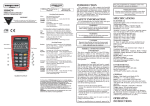
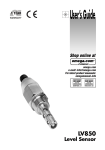
Where Do I Find Everything I Need for
Process Measurement and Control?
OMEGA…Of Course!
Shop online at www.omega.com
MADE IN
User’s Guide
TEMPERATURE
䡺
⻬
䡺
⻬
䡺
⻬
䡺
⻬
䡺
⻬
Thermocouple, RTD & Thermistor Probes, Connectors, Panels & Assemblies
Wire: Thermocouple, RTD & Thermistor
Calibrators & Ice Point References
Recorders, Controllers & Process Monitors
Infrared Pyrometers
PRESSURE, STRAIN AND FORCE
䡺
⻬
䡺
⻬
䡺
⻬
䡺
⻬
Transducers & Strain Gages
Load Cells & Pressure Gages
Displacement Transducers
Instrumentation & Accessories
FLOW/LEVEL
䡺
⻬
䡺
⻬
䡺
⻬
䡺
⻬
Rotameters, Gas Mass Flowmeters & Flow Computers
Air Velocity Indicators
Turbine/Paddlewheel Systems
Totalizers & Batch Controllers
Shop online at
pH/CONDUCTIVITY
䡺
⻬
䡺
⻬
䡺
⻬
䡺
⻬
pH Electrodes, Testers & Accessories
Benchtop/Laboratory Meters
Controllers, Calibrators, Simulators & Pumps
Industrial pH & Conductivity Equipment
www.omega.com
e-mail: [email protected]
DATA ACQUISITION
䡺
⻬
䡺
⻬
䡺
⻬
䡺
⻬
䡺
⻬
Data Acquisition & Engineering Software
Communications-Based Acquisition Systems
Plug-in Cards for Apple, IBM & Compatibles
Datalogging Systems
Recorders, Printers & Plotters
HEATERS
䡺
⻬
䡺
⻬
䡺
⻬
䡺
⻬
䡺
⻬
Heating Cable
Cartridge & Strip Heaters
Immersion & Band Heaters
Flexible Heaters
Laboratory Heaters
ENVIRONMENTAL
MONITORING AND CONTROL
䡺
⻬
䡺
⻬
䡺
⻬
䡺
⻬
䡺
⻬
䡺
⻬
Metering & Control Instrumentation
Refractometers
Pumps & Tubing
Air, Soil & Water Monitors
Industrial Water & Wastewater Treatment
pH, Conductivity & Dissolved Oxygen Instruments
HHT21A
M3942/0303
Laser Tachometer
WARRANTY/DISCLAIMER
OMEGAnet ® Online Service
www.omega.com
Internet e-mail
[email protected]
Servicing North America:
USA:
ISO 9001 Certified
Canada:
One Omega Drive, P.O. Box 4047
Stamford CT 06907-0047
TEL: (203) 359-1660
e-mail: [email protected]
976 Bergar
Laval (Quebec) H7L 5A1, Canada
TEL: (514) 856-6928
e-mail: [email protected]
FAX: (203) 359-7700
FAX: (514) 856-6886
For immediate technical or application assistance:
USA and Canada: Sales Service: 1-800-826-6342 / 1-800-TC-OMEGA®
Customer Service: 1-800-622-2378 / 1-800-622-BEST®
Engineering Service: 1-800-872-9436 / 1-800-USA-WHEN®
TELEX: 996404 EASYLINK: 62968934 CABLE: OMEGA
Mexico:
En Espan˜ol: (001) 203-359-7803
FAX: (001) 203-359-7807
Benelux:
Postbus 8034, 1180 LA Amstelveen, The Netherlands
TEL: +31 (0)20 3472121
FAX: +31 (0)20 6434643
Toll Free in Benelux: 0800 0993344
e-mail: [email protected]
Czech Republic:
Frystatska 184/46, 733 01 Karviná, Czech Republic
TEL: +420 (0)59 6311899
FAX: +420 (0)59 6311114
Toll Free: 0800-1-66342
e-mail: [email protected]
France:
11, rue Jacques Cartier, 78280 Guyancourt, France
TEL: +33 (0)1 61 37 29 00
FAX: +33 (0)1 30 57 54 27
Toll Free in France: 0800 466 342
e-mail: [email protected]
e-mail: [email protected]
[email protected]
Servicing Europe:
Germany/Austria: Daimlerstrasse 26, D-75392 Deckenpfronn, Germany
TEL: +49 (0)7056 9398-0
Toll Free in Germany: 0800 639 7678
e-mail: [email protected]
United Kingdom:
ISO 9002 Certified
FAX: +49 (0)7056 9398-29
One Omega Drive, River Bend Technology Centre
Northbank, Irlam, Manchester
M44 5BD United Kingdom
TEL: +44 (0)161 777 6611
FAX: +44 (0)161 777 6622
Toll Free in United Kingdom: 0800-488-488
e-mail: [email protected]
It is the policy of OMEGA to comply with all worldwide safety and EMC/EMI regulations that
apply. OMEGA is constantly pursuing certification of its products to the European New Approach
Directives. OMEGA will add the CE mark to every appropriate device upon certification.
The information contained in this document is believed to be correct, but OMEGA Engineering, Inc. accepts
no liability for any errors it contains, and reserves the right to alter specifications without notice.
WARNING: These products are not designed for use in, and should not be used for, human applications.
OMEGA ENGINEERING, INC. warrants this unit to be free of defects in materials and workmanship for a
period of 13 months from date of purchase. OMEGA’s WARRANTY adds an additional one (1) month
grace period to the normal one (1) year product warranty to cover handling and shipping time. This
ensures that OMEGA’s customers receive maximum coverage on each product.
If the unit malfunctions, it must be returned to the factory for evaluation. OMEGA’s Customer Service
Department will issue an Authorized Return (AR) number immediately upon phone or written request.
Upon examination by OMEGA, if the unit is found to be defective, it will be repaired or replaced at no
charge. OMEGA’s WARRANTY does not apply to defects resulting from any action of the purchaser,
including but not limited to mishandling, improper interfacing, operation outside of design limits,
improper repair, or unauthorized modification. This WARRANTY is VOID if the unit shows evidence of
having been tampered with or shows evidence of having been damaged as a result of excessive corrosion;
or current, heat, moisture or vibration; improper specification; misapplication; misuse or other operating
conditions outside of OMEGA’s control. Components which wear are not warranted, including but not
limited to contact points, fuses, and triacs.
OMEGA is pleased to offer suggestions on the use of its various products. However,
OMEGA neither assumes responsibility for any omissions or errors nor assumes liability for any
damages that result from the use of its products in accordance with information provided by
OMEGA, either verbal or written. OMEGA warrants only that the parts manufactured by it will be
as specified and free of defects. OMEGA MAKES NO OTHER WARRANTIES OR
REPRESENTATIONS OF ANY KIND WHATSOEVER, EXPRESS OR IMPLIED, EXCEPT THAT OF TITLE,
AND ALL IMPLIED WARRANTIES INCLUDING ANY WARRANTY OF MERCHANTABILITY AND
FITNESS FOR A PARTICULAR PURPOSE ARE HEREBY DISCLAIMED. LIMITATION OF
LIABILITY: The remedies of purchaser set forth herein are exclusive, and the total liability of
OMEGA with respect to this order, whether based on contract, warranty, negligence,
indemnification, strict liability or otherwise, shall not exceed the purchase price of the
component upon which liability is based. In no event shall OMEGA be liable for
consequential, incidental or special damages.
CONDITIONS: Equipment sold by OMEGA is not intended to be used, nor shall it be used: (1) as a “Basic
Component” under 10 CFR 21 (NRC), used in or with any nuclear installation or activity; or (2) in medical
applications or used on humans. Should any Product(s) be used in or with any nuclear installation or
activity, medical application, used on humans, or misused in any way, OMEGA assumes no responsibility
as set forth in our basic WARRANTY/ DISCLAIMER language, and, additionally, purchaser will indemnify
OMEGA and hold OMEGA harmless from any liability or damage whatsoever arising out of the use of the
Product(s) in such a manner.
RETURN REQUESTS/INQUIRIES
Direct all warranty and repair requests/inquiries to the OMEGA Customer Service Department. BEFORE
RETURNING ANY PRODUCT(S) TO OMEGA, PURCHASER MUST OBTAIN AN AUTHORIZED RETURN
(AR) NUMBER FROM OMEGA’S CUSTOMER SERVICE DEPARTMENT (IN ORDER TO AVOID
PROCESSING DELAYS). The assigned AR number should then be marked on the outside of the return
package and on any correspondence.
The purchaser is responsible for shipping charges, freight, insurance and proper packaging to prevent
breakage in transit.
FOR WARRANTY RETURNS, please have the
following information available BEFORE
contacting OMEGA:
1. Purchase Order number under which the product
was PURCHASED,
2. Model and serial number of the product under
warranty, and
3. Repair instructions and/or specific problems
relative to the product.
FOR NON-WARRANTY REPAIRS, consult OMEGA
for current repair charges. Have the following
information available BEFORE contacting OMEGA:
1. Purchase Order number to cover the COST
of the repair,
2. Model and serial number of the product, and
3. Repair instructions and/or specific problems
relative to the product.
OMEGA’s policy is to make running changes, not model changes, whenever an improvement is possible. This affords
our customers the latest in technology and engineering.
OMEGA is a registered trademark of OMEGA ENGINEERING, INC.
© Copyright 2003 OMEGA ENGINEERING, INC. All rights reserved. This document may not be copied, photocopied,
reproduced, translated, or reduced to any electronic medium or machine-readable form, in whole or in part, without the
prior written consent of OMEGA ENGINEERING, INC.
NOTES
Safeguards and Precautions
1.
Read and follow all instructions in this manual carefully,
and retain this manual for future reference.
2.
Do not use this instrument in any manner inconsistent
with these operating instructions or under any
conditions
that
exceed
the
environmental
specifications stated.
3.
Making measurements in close proximity to rotating
equipment can be dangerous. Keep all loose clothiing
and hair away from exposed moving machinery.
Properly replace all machinery guards after
completing measurement.
4.
The socket on the front of the instrument is for use
with a remote charger. Only use model R-5 (115 Vac)
or R-6 (230 Vac) rechargers to charge the instrument.
5.
The HHT21A has a laser beam
light source. Do not view the
laser beam directly as it could be
hazardous to the eyes. Do not
point the laser beam into another
person’s eyes. Do not view the
laser beam with telescopic
devices.
6.
AVOID EXPOSURE
LASER RADIATION IS EMITTED
FROM THIS APERTURE
LASER RADIATION
AVOID DIRECT EYE EXPOSURE
PEAK POWER
3mw
650nm
WAVELENGTH
CLASS IIIA LASER PRODUCT
With exception of replacing the batteries, this
instrument is not user serviceable. For technical
assistance, contact the sales organization from which
you purchased the product.
TABLE OF CONTENTS
SPECIFICATIONS ................................................................ 1
OVERVIEW .......................................................................... 2
OPERATION ......................................................................... 2
USING THE HHT21A WITH A REMOTE OPTICAL SENSOR
(HHT20-ROS) ........................................................................ 3
CALIBRATION AND SELF-TEST .......................................... 3
BATTERIES .......................................................................... 5
of the way. It may also be convenient to keep a spare supply of reflective
tape in the free area underneath this cover.
The instrument will provide six to eight hours of continuous operation on a
single set of batteries, depending on the type used. The instrument is
provided with a built-in charging network, which works in conjunction with
the optional NiCad batteries. The optional recharger plugs into the single
jack located next to the optical lens at the front end of the instrument.
Fourteen to sixteen hours is required for a complete recharge. When the
battery voltage in the HHT21A is getting low, the display will blink
“LO BAT” to indicate that the batteries need to be replaced.
NOTE:
Only use model R-5B (115 Vac) or R-6B (230 Vac) rechargers
with NiCad batteries. Do not attempt to charge non-rechargeable
batteries.
ALWAYS DISPOSE OF BATTERIES IN A SAFE AND RESPONSIBLE
MANNER.
CLEANING ........................................................................... 5
CLEANING
To clean the instrument, wipe with a damp cloth using mild soapy solution.
5
SPECIFICATIONS
This product is designed for indoor or outdoor use under the following
conditions (per IEC1010-1):
Remote/Internal
Switch
Internal Optics
Lens
Recharger Jack
Figure 1 HHT21A-R
with Optional Remote Sensor (HHT20-ROS)
CALIBRATION AND SELF-TEST
The HHT21A SERIES is a crystal controlled digital instrument that requires
no calibration. However, the accuracy of the instrument can be checked at
any time by aiming it at an old style fluorescent light and observing 7200 ±2
RPM. In countries with 50 Hz. power line frequency, the display will read
6000 ±2 RPM.
NOTE:
The Tachometer will not correctly read on energy-efficient
fluorescent lights.
BATTERIES
The HHT21A SERIES operates from four ‘AA’ size batteries which are
located under the hinged top of the instrument. To access these batteries,
grip the tapered cover at the optical lens end of the instrument and pull up.
The cover is hinged at the display end of the instrument and pivots fully out
4
Speed Range:
5 RPM to 100,000 RPM
Accuracy:
± 1 RPM or .01% of reading
Resolution:
1 RPM
Display:
6-digit 0.45” high liquid crystal
Display Update:
Twice per second
On-Target Indication: Target (Bullseye) on lower left of display
Operating Distance: Range: Up to 10 feet [3.1 m] from leading edge
of reflective tape
Angle: Up to 45° from perpendicular to leading
edge of reflective tape
Power-On Switch:
Pistol grip trigger - may be locked on with latching
push-button for longer duration measurements
Auto hold of last measurement for 90 seconds
Optical System:
Visible laser light source
WARNING:
Do not view the laser beam directly as it
could be hazardous to the eyes. Do not
point the laser beam into another person’s
eyes. Do not view the laser beam with
telescopic devices.
Time Base:
Crystal controlled
Power Source:
4 “AA” batteries; Recharger socket provided for
optional rechargeable batteries
Recharger Input:
Max input 7.8 Vdc @ 50mA
Temperature:
41 °F [5 °C] to 104 °F [40 °C]
Humidity:
Maximum relative humidity 80% for temperature
up to 88 °F [31 °C] decreasing linearly to 50%
relative humidity at 104 °F [40 °C]
AVOID EXPOSURE
LASER RADIATION IS EMITTED
FROM THIS APERTURE
LASER RADIATION
AVOID DIRECT EYE EXPOSURE
PEAK POWER
3mw
650nm
WAVELENGTH
CLASS IIIA LASER PRODUCT
1
Dimensions (LxWxH):6.13” x 3.25” x 1.75 “ plus 4.75” handle
[155.7 mm x 82.6 mm x 44.5 mm x 120.7 mm]
Weight:
1.25 lbs [0.57 kg]
OVERVIEW
The HHT21A SERIES combines the accuracy and safety of a non-contact
optical tachometer with the convenience and ease of operation of a pistol
grip instrument. The instrument provides non-contact measurement of
rotational speed to an accuracy of .01% of reading. It reads RPM directly to
the nearest RPM, and a ‘on-target’ indicator is provided to verify the
instrument is properly aligned on a target and receiving valid information.
OPERATION
The HHT21A measures rotational speed from a single pulse per revolution.
This pulse is supplied by marking the rotating shaft with a visible reflective
tape target. The HHT21A is equipped with a built-in laser light source
providing a bright red beam which is aimed at the reflective tape located on
the rotating shaft. The pulse from the reflective tape is received back
through a single lens reflex optical system and detected by a photocell
inside the instrument. The HHT21A then computes the rotational speed
and displays it to a resolution of 1 RPM.
To operate the instrument, simply aim it at the reflective tape while holding
it at a distance of 1 inch [25.4 mm] to 10 feet [3.1 m] making sure to observe
laser safety precautions. Squeeze the pistol grip trigger, and read the indicated
speed. The on-target indicator must be on. The display is updated up to
twice per second.
For longer duration measurements, the trigger latch on the side of the pistol
grip handle can be depressed after pulling the trigger, and the instrument
may be mounted on the 1/4-20 threaded bushing at the base of the handle.
2
When the trigger is released, the HHT21A will hold the last measurement
taken and display it for up 90 seconds.
On very small shafts, the HHT21A will work down to a reflective tape size
of approximately 1/8 inch [3.2 mm] square. However, with this small tape
size, it would be necessary to operate the instrument very close to the
rotating shaft and insure it is held steady. For normal operation, a tape size
of approximately 1/2 inch [12.7 mm] square or larger is recommended, and
on very large diameter shafts or for very high-speed applications, a larger
size piece of tape may be required. It is also recommended that the reflective
tape be viewed just slightly off the perpendicular. The HHT21A will
operate at angles from 0 to 45 degrees, but best results are obtained by
aiming the instrument at the reflective tape at approximately a 10 to 20
degree angle. This insures that only pulses from the reflective tape are
received by the instrument and minimizes the problem of interference from
a highly polished surface or varying ambient lighting.
USING THE HHT21A-R WITH A REMOTE OPTICAL SENSOR
The HHT21A-R version of the tachometer has a provision for using the
optional HHT20-ROS Remote Optical Sensor. In addition to the standard
built-in optics of the HHT21A SERIES, a 1/8 inch [3.5 mm] phone jack is
provided on the front panel of the Tachometer to accept a remote optical
sensor plug. A toggle switch on the optics panel selects internal or remote
operation.
For applications requiring the remote optical sensor, move the Remote/
Internal switch to the remote position to disable the internal optics of the
Tachometer. When the trigger is pulled or latched, the remote optical sensor
can be used for measurements. The HHT20-ROS Remote Optical Sensor
operates 3 feet [0.9 m] and ±45° from the reflective tape.
3