1
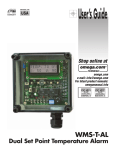
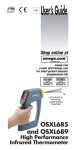
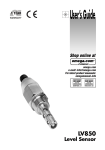
User’s Guide
LVR300 Series
Shop online at
omega.com
e-mail: [email protected]
For latest product manuals:
omegamanual.info
LVR300 Series
Continuous Level Switch System
OMEGAnet ® Online Service
omega.com
Internet e-mail
[email protected]
Servicing North America:
U.S.A.:
ISO 9001 Certified
Canada:
One Omega Drive, P.O. Box 4047
Stamford, CT 06907-0047
TEL: (203) 359-1660
e-mail: [email protected]
976 Bergar
Laval (Quebec) H7L 5A1, Canada
TEL: (514) 856-6928
e-mail: [email protected]
FAX: (203) 359-7700
FAX: (514) 856-6886
For immediate technical or application assistance:
U.S.A. and Canada: Sales Service: 1-800-826-6342 / 1-800-TC-OMEGA®
Customer Service: 1-800-622-2378 / 1-800-622-BEST®
Engineering Service: 1-800-872-9436 / 1-800-USA-WHEN®
TELEX: 996404 EASYLINK: 62968934 CABLE: OMEGA
Mexico:
En Español: (001) 203-359-7803
FAX: (001) 203-359-7807
e-mail: [email protected]
[email protected]
Servicing Europe:
Benelux:
Postbus 8034, 1180 LA Amstelveen, The Netherlands
TEL: +31 (0)20 3472121
FAX: +31 (0)20 6434643
Toll Free in Benelux: 0800 0993344
e-mail: [email protected]
Czech Republic:
Frystatska 184, 733 01 Karviná, Czech Republic
TEL: +420 (0)59 6311899
FAX: +420 (0)59 6311114
Toll Free: 0800-1-66342
e-mail: [email protected]
France:
11, rue Jacques Cartier, 78280 Guyancourt, France
TEL: +33 (0)1 61 37 2900
FAX: +33 (0)1 30 57 5427
Toll Free in France: 0800 466 342
e-mail: [email protected]
Germany/Austria: Daimlerstrasse 26, D-75392 Deckenpfronn, Germany
TEL: +49 (0)7056 9398-0
Toll Free in Germany: 0800 639 7678
e-mail: [email protected]
United Kingdom:
ISO 9002 Certified
FAX: +49 (0)7056 9398-29
One Omega Drive, River Bend Technology Centre
Northbank, Irlam, Manchester
M44 5BD United Kingdom
TEL: +44 (0)161 777 6611
FAX: +44 (0)161 777 6622
Toll Free in United Kingdom: 0800-488-488
e-mail: [email protected]
It is the policy of OMEGA Engineering, Inc. to comply with all worldwide safety and EMC/EMI
regulations that apply. OMEGA is constantly pursuing certification of its products to the European New
Approach Directives. OMEGA will add the CE mark to every appropriate device upon certification.
The information contained in this document is believed to be correct, but OMEGA accepts no liability for any
errors it contains, and reserves the right to alter specifications without notice.
WARNING: These products are not designed for use in, and should not be used for, human applications.
LVR300 Series Sensor Overview
Operating Principle
The complete LVR300 Series Sensor is designed to be a self-contained continuous level sensor and control, requiring only a power source. A 16-bit microcontroller with a 14-bit A/D
converter and a 12-bit D/A converter provides the necessary processing speed and
measurement accuracy. The signal is displayed with units using a back-lit LCD
graphical display and converted to a 4-20 mA signal. Two switch points
with either a positive or negative output can be programmed over the complete range.
The switching point hysteresis can be set separately in value and direction
(minimum/maximum switching value). Upward and downward crossings of switching points and error messages are
shown in the display with a flashing red LED that is easily visible from a distance.
Other parameters can be changed using codes, including: signal filter; selectable unit (inch, cm) includes automatic conversion of the values; selectable 0-20 mA or 4-20 mA output; value assignment of 4-20 mA (setting of zero point and
span). The complete housing can be rotated around the mechanical connection so that the correct reading position can be
set after mounting (installation).
This LVR300 Series is very easy to use, as dialog messages are displayed for the user. It can even be set when wearing
protective gloves, if necessary.
Programming Overview
The LVR300 Series’ programming ring can be rotated from the Neutral center position to
Position 1 and Position 2. The following actions are possible:
A – Display of parameters with Position 1 (simultaneous display of the set parameters) –
Turn the programming ring left to Position 1 to begin cycling through these programming
parameters: Switching points S1 and S2, Hysteresis direction of S1 and S2,
Hysteresis Hyst 1 and Hyst 2, Code (allows editing of additional parameters),
Filter, Units, Output, 4 mA Value and 20 mA value. See following pages for
detailed programming instructions.
B – Editing with Position 2
Turn the programming ring to the right to Position 2 and a flashing cursor
appears showing the position to be changed. With repeated turning to
Position 2, the values are increased. By turning to Position 1, you obtain
the next position. Each position can be edited in this way. If there is no
action within 5 seconds, the device returns to the normal display section without the change being accepted, and you will have to cycle
through the program again.
Value
Example of hysteresis setting:
Examples with S1 as maximum switching point
and as minimum switching point:
All specifications are subject to change without notice.
Terminal Assignment
1
2
LVR
Sensor
3
4
C – Saving the change with Position 1
Turning one time toward Position 1 after quitting the last value signifies
acceptance of the change.
Programming protection:
The programming ring can be pulled off,
inverted and replaced. This will prevent further
programming resulting from turning the ring in
either direction.
Programming Ring turns from
Position 1 to Position 2
5
Z = load
Alarm range
24 to 30 VDC
4-20 mA
0V
S1
S2
brown
white
z
blue
black
z
z
gray
Exam ple: PNP
or
NPN
The switch points are automatically changing to positive or negative, depending on
your interface.
S1 max.
Hyst 1
Time
Value
Mating Connector
M12 x 1, 5-position female, shielded, straight or
M12 x 1, 5-position female, shielded, right angle
Hyst 1
S1 min.
Alarm range
Time
Sources: Hirschmann, Binder,
rde Connectors & Cables or
comparable connector
© Copyright Omega Engineering Inc. – 4/05
LVR300 Series Programming Positions & Operation
On power-up, the company logo is displayed, followed by the preset level/unit measurement. Changing the level (by float movement)
will be reflected in the display. If the level is at either of the preset switch levels S1 or S2 (the upper and lower levels), the display will
also be alternating between the S1 (or S2) status indication with the level reading. The Switch Active status is also indicated by a
flashing LED.
By rotating the program ring to Position 1 (P1, toward the left) and then back to Neutral, the proProgram
gram steps to the S1 setting. The level for activation of the S1 switch is indicated, and may be
Position 1
edited by turning the program ring to the P2 position (see below). This will highlight the tenths
digit. The digit value is advancing by alternating the program ring from center to the right P2
position. Turning the ring to the P1 position accepts that value and moves to the next digit.
Turning the ring to Neutral and then back to P1 will cycle through all of the digits and then accept the
values.
Neutral
Program
Position 2
2
1
PROGRAMMING POSITIONS
The P1 to Neutral movement steps the program through positions in the following sequence:
LOGO
Logo display, only shown on initial power-up.
###.#
Inches (cm)
S1
###.#
S1
Min. (Max.)
Hyst 1
##.#
S2
###.#
S2
Max. (Min.)
Hyst 2
##.#
Code
000
###.#
Inches (cm)
###.#
OR
< S1
Current float level. At right, the switch active status is indicated and alternates with the regular measurement display, and the LED is flashing.
Switch point 1 value,
sets level for activation.
MODIFYING OPERATING PARAMETERS
Switch point 1 is active if the level
is below (or below) S1.
1 Turn the programming ring to the right to Position 2, and then
back to Neutral, to bring up the editing cursor in the first decimal place.
Hysteresis threshold added to
switch point 1 for switch = active.
Switch point 2 value,
sets level for activation.
Switch point 2 is active if the level
is above (or below) S2.
Hysteresis threshold added to
switch point 2 for switch = active.
From any of the Programming Position steps noted at left, follow
these steps to modify the operating parameter:
2 Turning the ring to the right and back to Neutral increases the
current decimal place to the next highest value.
3 Turning the ring to the left and back to Neutral moves the cursor on to the next decimal position. Repeat step 2 to edit the
current position.
4 To confirm the new value, continue to turn the ring to the left
and back to neutral until you cycle through all of the decimal
places and the next parameter shows on the display.
ENTERING ADDITIONAL PROGRAM PARAMETERS
After reaching the Code step, enter 111 by turning the ring P1 to
Neutral, and you can access these additional parameters:
Filter
To access other program parameters, rotate ring to P2
and change 000 to 111.
Returns to regular display
of current float level.
1
4
##.#
Units
2
Output
Inch (cm)
3
4-20 mA
Time for the measurement to
respond (seconds)
Switch between inches
and cm; Switch points are
converted automatically
4 mA
20 mA
###.#
###.#
###.#
Inches (cm)
Set the 4 mA level
(may be higher than
the min. level)
5
Switchable to
0-20 mA
6
Set the
20 mA level
Returns to regular display mode
PROTECTING YOUR PROGRAMMING PARAMETERS
1. Pull off the ring. Keep it as a
personal key.
2. Use ring in reverse position
on the sensor (PROG.LOCK
position).
All specifications are subject to change without notice.
Enter Code 989 to return to Factory Default Settings.
Step-by-step program examples are illustrated on the following pages.
Note: During the programming process, if there is no new action
taken within 30 seconds, the sensor will return to “measurement
display” without saving your changes. You will have to go through
the entire program a second time to re-program the unit.
© Copyright Omega Engineering Inc. – 4/05
LVR300 Series Quick Reference – Programming Steps
HOW TO MODIFY THE SENSOR
OPERATING PARAMETERS
HOW TO ENTER ADDITIONAL
PARAMETERS & INFORMATION
Example: S1 = +18.6 Inches (or cm)
+ 0.0
Inch (cm)
If the ring is turned
right toward Position 2
(EDIT), a cursor
appears while the
parameter you want to
modify is displayed.
S1
+25.5
S1
Turning right effects
a change to the next
higher figure.
+25.
S1
Turning left moves the
cursor to the next decimal position.
+25.6
Move ring 3 times to
the right, alternating to
Position 2 and center,
and you will see a
3-digit increase to the
figure marked by the
cursor’s location.
Turning right
effects an increase
of the figure.
Turning left
moves the cursor
to the next decimal position.
Code
000
Code
001
Code
001
Code
S1
011
+21.6
Code
3x
011
S1
Code
+28.6
111
S1
+18.6
9x
S1
+18.6
Turn the ring 2 times to
the left, toward
Position 1, and the cursor disappears. The
modified S1 is now visable and the next parameter is shown
automatically.
When the program
ring is turned to
the right toward
Position 2 (EDIT),
a cursor appears
at the parameter
to modify.
2x
S1
By turning the ring
to the left toward
Position 1,
the cursor disappears and enters
the code. The
next parameter
arrives automatically.
Filter
1
Units
Inch (cm)
Output
4-20 mA
Min.
4 mA
0
20 mA
80
Cursor flashing
NOTE: If you remain idle in the programming stage
for 30 seconds, the display indication will return to
“measurement display” without saving your new settings. You will have to cycle through the program
again to make your changes.
All specifications are subject to change without notice.
In regular display
mode again.
Filter for display and
analog output. (It is a
FIFO filter and the
time to accomplish the
actual measurement
value corresponds to
the seconds shown in
the display.)
Selection of various
units (inches, cm, PSI).
Display and switch
points are recalculated
automatically.
Set analog output
4-20 mA or 0-20 mA.
Start of analog
output range
(in the selected unit).
End of analog
output range
(in the selected unit).
+ 0.0
Inch (cm)
TO RETURN TO THE FACTORY DEFAULT SETTING:
Set the code to 989.
All individual parameters are now overwritten.
LVR300 Continuous Level Sensor Installation Guide
General Information
1. Continuous Level Sensors should be installed rigidly so the float is free to move as the
liquid level changes.
2. Continuous Level Sensors should be mounted in a tank area free of severe turbulence
or protected from such turbulence by appropriate and adequate slosh shields.
3. Continuous Level Sensors stems should be vertical for best results, but satisfactory
operation is possible in most liquids with the stem at up to a 30º angle from vertical.
4. Care should be taken that Continuous Level Sensors are always operated within electrical ratings.
Cautions
1. The pressure, temperature and electrical limitations shown for the specified level sensor
must not be exceeded.
2. The pressures and temperatures must take into consideration possible surges in the
temperature and pressure of the system.
3. The liquids used must be compatible with the materials of construction. Specifications
of materials will be given upon request.
4. Life expectancy of the sensor varies with applications.
5. Ambient temperature changes can affect sensor set points, since specific gravities of
liquids vary with temperature. Consult factory for assistance.
6. Level sensors have been designed to be shock and vibration resistant. For maximum
life, both should be minimized. Consult factory for assistance.
7. Excessive contaminants in fluid may inhibit float operation and occasional wipe down
may be necessary.
8. Physical damage to product may render product unserviceable.
9. Installation in a vessel made from magnetic materials may affect operation.
Shop online at: omega.com
e-mail: [email protected]
For latest product manuals: omegamanual.info
WARRANTY/DISCLAIMER
OMEGA ENGINEERING, INC. warrants this unit to be free of defects in materials and workmanship for a
period of 13 months from date of purchase. OMEGA’s WARRANTY adds an additional one (1) month
grace period to the normal one (1) year product warranty to cover handling and shipping time. This
ensures that OMEGA’s customers receive maximum coverage on each product.
If the unit malfunctions, it must be returned to the factory for evaluation. OMEGA’s Customer Service
Department will issue an Authorized Return (AR) number immediately upon phone or written request.
Upon examination by OMEGA, if the unit is found to be defective, it will be repaired or replaced at no
charge. OMEGA’s WARRANTY does not apply to defects resulting from any action of the purchaser,
including but not limited to mishandling, improper interfacing, operation outside of design limits,
improper repair, or unauthorized modification. This WARRANTY is VOID if the unit shows evidence of
having been tampered with or shows evidence of having been damaged as a result of excessive corrosion;
or current, heat, moisture or vibration; improper specification; misapplication; misuse or other operating
conditions outside of OMEGA’s control. Components in which wear is not warranted, include but are not
limited to contact points, fuses, and triacs.
OMEGA is pleased to offer suggestions on the use of its various products. However,
OMEGA neither assumes responsibility for any omissions or errors nor assumes liability for any
damages that result from the use of its products in accordance with information provided by
OMEGA, either verbal or written. OMEGA warrants only that the parts manufactured by the
company will be as specified and free of defects. OMEGA MAKES NO OTHER WARRANTIES OR
REPRESENTATIONS OF ANY KIND WHATSOEVER, EXPRESSED OR IMPLIED, EXCEPT THAT OF
TITLE, AND ALL IMPLIED WARRANTIES INCLUDING ANY WARRANTY OF MERCHANTABILITY
AND FITNESS FOR A PARTICULAR PURPOSE ARE HEREBY DISCLAIMED. LIMITATION OF
LIABILITY: The remedies of purchaser set forth herein are exclusive, and the total liability of
OMEGA with respect to this order, whether based on contract, warranty, negligence,
indemnification, strict liability or otherwise, shall not exceed the purchase price of the
component upon which liability is based. In no event shall OMEGA be liable for
consequential, incidental or special damages.
CONDITIONS: Equipment sold by OMEGA is not intended to be used, nor shall it be used: (1) as a “Basic
Component” under 10 CFR 21 (NRC), used in or with any nuclear installation or activity; or (2) in medical
applications or used on humans. Should any Product(s) be used in or with any nuclear installation or
activity, medical application, used on humans, or misused in any way, OMEGA assumes no responsibility
as set forth in our basic WARRANTY/DISCLAIMER language, and, additionally, purchaser will indemnify
OMEGA and hold OMEGA harmless from any liability or damage whatsoever arising out of the use of the
Product(s) in such a manner.
RETURN REQUESTS/INQUIRIES
Direct all warranty and repair requests/inquiries to the OMEGA Customer Service Department. BEFORE
RETURNING ANY PRODUCT(S) TO OMEGA, PURCHASER MUST OBTAIN AN AUTHORIZED RETURN
(AR) NUMBER FROM OMEGA’S CUSTOMER SERVICE DEPARTMENT (IN ORDER TO AVOID
PROCESSING DELAYS). The assigned AR number should then be marked on the outside of the return
package and on any correspondence.
The purchaser is responsible for shipping charges, freight, insurance and proper packaging to prevent
breakage in transit.
FOR WARRANTY RETURNS, please have the
following information available BEFORE
contacting OMEGA:
1. Purchase Order number under which the product
was PURCHASED,
2. Model and serial number of the product under
warranty, and
3. Repair instructions and/or specific problems
relative to the product.
FOR NON-WARRANTY REPAIRS, consult OMEGA
for current repair charges. Have the following
information available BEFORE contacting OMEGA:
1. Purchase Order number to cover the COST
of the repair,
2. Model and serial number of the product, and
3. Repair instructions and/or specific problems
relative to the product.
OMEGA’s policy is to make running changes, not model changes, whenever an improvement is possible. This affords
our customers the latest in technology and engineering.
OMEGA is a registered trademark of OMEGA ENGINEERING, INC.
© Copyright 2005 OMEGA ENGINEERING, INC. All rights reserved. This document may not be copied, photocopied,
reproduced, translated, or reduced to any electronic medium or machine-readable form, in whole or in part, without the
prior written consent of OMEGA ENGINEERING, INC.
Where Do I Find Everything I Need for
Process Measurement and Control?
OMEGA…Of Course!
Shop online at omega.com
TEMPERATURE
Thermocouple, RTD & Thermistor Probes, Connectors, Panels & Assemblies
Wire: Thermocouple, RTD & Thermistor
Calibrators & Ice Point References
Recorders, Controllers & Process Monitors
Infrared Pyrometers
PRESSURE, STRAIN AND FORCE
Transducers & Strain Gages
Load Cells & Pressure Gages
Displacement Transducers
Instrumentation & Accessories
FLOW/LEVEL
Rotameters, Gas Mass Flowmeters & Flow Computers
Air Velocity Indicators
Turbine/Paddlewheel Systems
Totalizers & Batch Controllers
pH/CONDUCTIVITY
pH Electrodes, Testers & Accessories
Benchtop/Laboratory Meters
Controllers, Calibrators, Simulators & Pumps
Industrial pH & Conductivity Equipment
DATA ACQUISITION
Data Acquisition & Engineering Software
Communications-Based Acquisition Systems
Plug-in Cards for Apple, IBM & Compatibles
Datalogging Systems
Recorders, Printers & Plotters
HEATERS
Heating Cable
Cartridge & Strip Heaters
Immersion & Band Heaters
Flexible Heaters
Laboratory Heaters
ENVIRONMENTAL
MONITORING AND CONTROL
Metering & Control Instrumentation
Refractometers
Pumps & Tubing
Air, Soil & Water Monitors
Industrial Water & Wastewater Treatment
pH, Conductivity & Dissolved Oxygen Instruments
M-4213/0605