1
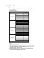
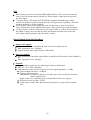
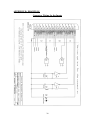
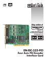
User’s Guide
Shop online at
omega.com
e-mail: [email protected]
For latest product manuals:
omegamanual.info
EN-EIC-325-PCI
Four Axis PCI Encoder
Interface Card
OMEGAnet ® Online Service
omega.com
Internet e-mail
[email protected]
Servicing North America:
U.S.A.:
ISO 9001 Certified
Canada:
One Omega Drive, P.O. Box 4047
Stamford, CT 06907-0047
TEL: (203) 359-1660
FAX: (203) 359-7700
e-mail: [email protected]
976 Bergar
Laval (Quebec) H7L 5A1, Canada
TEL: (514) 856-6928
FAX: (514) 856-6886
e-mail: [email protected]
For immediate technical or application assistance:
U.S.A. and Canada: Sales Service: 1-800-826-6342/1-800-TC-OMEGA®
Customer Service: 1-800-622-2378/1-800-622-BEST®
Engineering Service: 1-800-872-9436/1-800-USA-WHEN®
Mexico:
En Espan˜ol: (001) 203-359-7803
e-mail: [email protected]
FAX: (001) 203-359-7807
[email protected]
Servicing Europe:
Czech Republic:
Frystatska 184, 733 01 Karviná, Czech Republic
TEL: +420 (0)59 6311899
FAX: +420 (0)59 6311114
Toll Free: 0800-1-66342
e-mail: [email protected]
Germany/Austria: Daimlerstrasse 26, D-75392 Deckenpfronn, Germany
TEL: +49 (0)7056 9398-0
FAX: +49 (0)7056 9398-29
Toll Free in Germany: 0800 639 7678
e-mail: [email protected]
United Kingdom:
ISO 9002 Certified
One Omega Drive, River Bend Technology Centre
Northbank, Irlam, Manchester
M44 5BD United Kingdom
TEL: +44 (0)161 777 6611
FAX: +44 (0)161 777 6622
Toll Free in United Kingdom: 0800-488-488
e-mail: [email protected]
It is the policy of OMEGA Engineering, Inc. to comply with all worldwide safety and EMC/EMI
regulations that apply. OMEGA is constantly pursuing certification of its products to the European New
Approach Directives. OMEGA will add the CE mark to every appropriate device upon certification.
The information contained in this document is believed to be correct, but OMEGA accepts no liability for any
errors it contains, and reserves the right to alter specifications without notice.
WARNING: These products are not designed for use in, and should not be used for, human applications.
FOUR AXIS ENCODER INTERFACE CARD
MODEL
Version 2.01,
Oct. 2003
1
TABLE of CONTENTS
Section
Page
1
GENERAL DESCRIPTION . . . . . . . . . . . . . . . . . . . . . . . . . .
3
1.1
ENCODER INTERFACE . . . . . . . . . . . . . . . . . . . . . . . . . . . . .
3
1.1.1
IPC . . . . . . . . . . . . . . . . . . . . . . . . . . . . . . . . . . . . . . . . . . . . . . .
3
1.1.2
SOFTWARE OUTPUTS . . . . . . . . . . . . . . . . . . . . . . . . . . . . . .
3
1.1.3
SOFTWARE INPUTS . . . . . . . . . . . . . . . . . . . . . . . . . . . . . . . .
4
1.2
CARD’S HARDWARE I/O . . . . . . . . . . . . . . . . . . . . . . . . . . .
4
1.2.1
HARDWARE INPUTS . . . . . . . . . . . . . . . . . . . . . . . . . . . . . . .
4
1.2.2
HARDWARE OUTPUTS . . . . . . . . . . . . . . . . . . . . . . . . . . . . .
4
2.
CARD’S HARDWARE . . . . . . . . . . . . . . . . . . . . . . . . . . . . .
4
2.1
DATA BUS and ADDRESS BUS . . . . . . . . . . . . . . . . . . . . . .
4
2.2
PIN LAY-OUT . . . . . . . . . . . . . . . . . . . . . . . . . . . . . . . . . . . . .
5
3.
SOFTWARE INTERFACE WITH THE CARD . . . . . . . . .
7
3.1
INSTALLATION . . . . . . . . . . . . . . . . . . . . . . . . . . . . . . . . . . .
7
3.1.1
Windows . . . . . . . . . . . . . . . . . . . . . . . . . . . . . . . . . . . . . . . . . .
9
3.1.2
VB . . . . . . . . . . . . . . . . . . . . . . . . . . . . . . . . . . . . . . . . . . . . . . .
11
3.1.3
VC . . . . . . . . . . . . . . . . . . . . . . . . . . . . . . . . . . . . . . . . . . . . . . .
12
3.1.4
CPP . . . . . . . . . . . . . . . . . . . . . . . . . . . . . . . . . . . . . . . . . . . . . .
12
3.1.5
More . . . . . . . . . . . . . . . . . . . . . . . . . . . . . . . . . . . . . . . . . . . . .
12
3.2
INTRODUCTION TO THE FUNCTIONS . . . . . . . . . . . . . . .
13
3.3
CARD LEVEL FUNCTIONS . . . . . . . . . . . . . . . . . . . . . . . . . .
14
3.4
CHIP LEVEL FUNCTIONS . . . . . . . . . . . . . . . . . . . . . . . . . . .
15
3.4.1
ACTIVE CHIP . . . . . . . . . . . . . . . . . . . . . . . . . . . . . . . . . . . . .
15
3.4.2
I/O . . . . . . . . . . . . . . . . . . . . . . . . . . . . . . . . . . . . . . . . . . . . . . .
16
3.5
ENCODER LEVEL FUNCTIONS . . . . . . . . . . . . . . . . . . . . . .
17
3.5.1
RESOLUTION . . . . . . . . . . . . . . . . . . . . . . . . . . . . . . . . . . . . .
17
3.5.2
INDEX. . . . . . . . . . . . . . . . . . . . . . . . . . . . . . . . . . . . . . . . . . . .
18
3.5.3
SETPOINT . . . . . . . . . . . . . . . . . . . . . . . . . . . . . . . . . . . . . . . .
19
3.5.4
EVENT SIGNAL . . . . . . . . . . . . . . . . . . . . . . . . . . . . . . . . . . .
20
3.5.5
POSITION COUNTER . . . . . . . . . . . . . . . . . . . . . . . . . . . . . . .
22
3.6
ARGUMENTS . . . . . . . . . . . . . . . . . . . . . . . . . . . . . . . . . . . . .
23
APPENDIX A
SPECIFICATION . . . . . . . . . . . . . . . . . . . . . . . . . . . . . . . . .
25
APPENDIX B
DRAWINGS . . . . . . . . . . . . . . . . . . . . . . . . . . . . . . . . . . . . . .
28
APPENDIX C
CARD INSTALLATION . . . . . . . . .. . . . . . . . . . . . . . . . . . . .
30
APPENDIX D
PRODUCT DEVELOPMENT . . . . . . . . . . . . . . . . . . . . . . . .
39
2
1.
GENERAL DESCRIPTION
• The EN-EIC-325-PCI handles four axes of user's encoders. Each user's
encoder is directly attached to the Encoder Interface on the card.
• The EN-EIC-325-PCI includes eleven logical inputs, and three general
outputs.
• The EN-EIC-325-PCI is I/O mapped.
ENCODER INTERFACE
1.1.
Note: Each of the registers IPC, XPC and SPR, mentioned below,
represents an unsigned integer 24 bit number ranging from 0 to 16777215.
In case the user needs also negative values, he should refer to 16777215 as
–1 and so on, thus changing the range 0 – 16777215 to –8388608 –
+8388607
Each Encoder Interface includes the following elements:
1.1.1. IPC
The IPC (Internal Position Counter) is updated continuously according to
the input from user's encoders.
The updating of the IPC is affected by the Clock Resolution, that may be
set to 1, 2 or 4 Clocks/Cycle.
1.1.2. SOFTWARE OUTPUTS
a.
b.
The XPC (eXternal Position Counter) is a latch counter being equalized
to the IPC upon user's request – either via PC’s software, or by a
hardware (real-time) input.
"Event Signal" – produced when a pre-defined condition is met.
This software Event Signal is supplied also in the hardware outputs as
described in section 1.2.2 / ii. The user may select one of the following as
the pre-defined condition that becomes the trigger of the event:
• IPC = SPR
Each Encoder Interface includes an SPR (Set Point Register) being
adjustable by the user.
In case the user selects this condition, an event occurs when IPC =
SPR.
• IPC Overflow
In case the user selects this condition, an event occurs when there's
overflow in the IPC, that is, IPC changes from 16777215 to 0, or
vice versa.
• Index
In case the user selects this condition, an event occurs when an index
(marker) signal arrives from user's encoder.
3
1.1.3. SOFTWARE INPUTS
a.
b.
Data Request to request an XPC update.
For example, upon Data Request on the A axis, the following operation is
done:
XPC A ⇐ IPC A
Notes:
1. Data Request may be applied on a single axis, or (all at once) on:
axes pair (A+B or C+D), or all four axes.
2. Besides this software Data Request, there is also a hardware (real-time)
Data Request applied on all four axes, as described in section 1.2.1 / ii.
Reset to clear the IPC.
For example, upon Reset on the A axis, the following operation is done:
IPC A ⇐ 0
Note: Reset may be applied on a single axis, or (all at once) on an
axes pair (A+B or C+D).
CARD'S HARDWARE I/O
1.2.
1.2.1. HARDWARE INPUTS
i. Inputs #1–#10: Ten general inputs (reflected by software outputs).
ii. Input #11: Data Request to request all XPC’s update:
Upon this hardware Data Request, the following operations are done (all at once):
XPC A ⇐ IPC A ; XPC B ⇐ IPC B ; XPC C ⇐ IPC C ; XPC D ⇐ IPC D .
In other words – this Data Request is a hardware real-time equivalent to the software
function RequestPositionCounter (CardHandle, Encoder4, OutputsMirror)
(this is function #26 in section 3.5.5.) .) The minimal pulse width should be 20 ns;
the ‘snapshot’ is produced when the pulse goes low.
1.2.2. HARDWARE OUTPUTS
a.
b.
Three general outputs (reflecting software inputs).
Four outputs of the Event Signals, as described in section 1.1.2 / ii. The user
may define these outputs to be held until he sends an explicit "Clear" request.
2. CARD'S HARDWARE
The EN-EIC-325-PCI uses the PCI bus of the PC.
2.1.
DATA BUS and ADDRESS BUS
* The Data bus is 32 bits connected to the PCI.
* The Address bus is 32 bits (I/O access only, on lower 1MB mode).
* The Address access space is 16 bytes, located from Base Address to
Base Address + 15. The Base Address is allocated by the system each PC
power-up.
* Bus controls – see the PCI standard version 2.1.
4
2.2.
PIN LAY-OUT
The drawings of the input/output connections are in Appendix B.
Encoder Inputs
Function
Encoder A
Encoder B
Encoder C
Encoder D
Vcc
Index+
GND
Index–
Sine– / Phase A–
Sine+ / Phase A+
Cosine+ / Phase B+
Cosine– / Phase B–
GND
Vcc
Index+
Sine+ / Phase A+
Index–
Sine– / Phase A–
Cosine– / Phase B–
Cosine+ / Phase B+
Vcc
GND
Index–
Index+
Sine+ / Phase A+
Cosine+ / Phase B+
Sine– / Phase A–
Cosine– / Phase B–
Vcc
Index+
GND
Index–
Sine– / Phase A–
Sine+ / Phase A+
Cosine+ / Phase B+
Cosine– / Phase B–
GND
D-Type
44 pin No.
31
17
2
32
18
3
33
4
20
5
35
21
6
36
22
7
23
38
24
9
39
25
10
40
41
27
12
42
28
13
43
14
30
Notes:
1. Total max. current 0.7A.
2. The inputs can be sine (sine and cosine) or square (phases A and B).
3. For single ended inputs use the ‘–’ input only.
The two non-connected wires per each encoder (Sine+ and Cosine+
should be floating, not grounded.
4. All the five GND pins (2, 20, 38, 12 and 30) are shortened. They
appear five times to make the wiring easier.
5
Logical Inputs
D-Type
44 pin No.
16
1
19
34
37
8
26
11
29
44
15
30
Function
Input #2
Input #1
Input #3
Input #4
Input #5
Input #11
Input #7
Input #6
Input #8
Input #9
Input #10
GND
ENCODERS' EVENT SIGNALS AND GENERAL OUTPUTS
Function
VExt+
Event Signal
General Output
VExt–
Encoder A
Encoder B
Encoder C
Encoder D
Output #1
Output #2
Output #3
D-Type
9 pin No.
1
6
2
7
3
8
4
9
5
Notes:
1. Max. (consumed) current 15 mA + outputs drained current.
2. +/– VExt = 5–24 V.
6
3. SOFTWARE INTERFACE WITH THE CARD
3.1.
INSTALLATION
The main files and folders of the software package are as
follows:
Win95_98
Install.exe
WRTdevN.VxD (Ten files: N=0,...,9)
ImsEncPci.ocx
VB
VC
WinNT
WinRT.sys
ImsEic325-PCINT4.reg
Win2K
EIC325_P.sys
ImsEic325-PCIWDM.inf
WinXP
EIC325_P.sys
ImsEic325-PCIWDM.inf
OCX for WinNT/2K/XP
ImsEncPci.ocx
VB
VC
ReadMe.txt
EncPciConst.h
EncPciBasicTest
DLL for WinNT/2K/XP
EIC325PCI.dll
EIC325PCI.lib
VB
VC
ReadMe.txt
EncPciConst.h
EncPciFunctions.h
EncPciBasicTest
CPP
More
Copy these folders (you may skip the irrelevant items) under some new folder
on your hard disk, say ‘C:\ImsEnc325-PCI’.
7
The VB folders
The VB folders include an illustration program, which is
essential for any user, not only the VB programmer. For any
environment you are using – refer to the relevant VB folder.
Note:
If Visual Basic is NOT installed on your computer, then
before running the (VB produced) program EncPciTest.exe
(recommended), please verify that:
1. Your WinSysPath folder includes the following two files:
* Richtx32.ocx
* Riched32.dll
2. The Richtx32.ocx file is registered. It should be, as it is
self-registering. However, if a manual registering is still
required, apply:
Start, Run, ‘Regsvr32 WinSysPath\Richtx32.ocx’
WinSysPath is:
If needed, you’ll find the above two files in the software
package.
8
3.1.1. Windows
The various Windows folders supply the files required for the driver
installation. The Win95/98 driver includes an ActiveX control. The
WinNT/2K/XP drivers include two options: an ActiveX control and a
DLL. The DLL uses the popular ‘stdcall’ calling convention recognizable by
VB, VC, Delphi etc. The ActiveX control and the DLL are implemented by a
WinRT-based solution. They may be installed even if your system already
includes WinRT-based solutions, provided that the total number of solutions
won't exceed 10 (Win95/98) or 32 (WinNT/2K/XP).
?After performing the driver installation relevant to your Windows
(95/98/NT/2K/XP) you may proceed to the card installation (see appendix C).
Win95/98
• Refer to the Win95_98 folder.
• Run the "Install.exe" program, which automatically copies the required
files and updates the registry:
• The file ImsEncPci.ocx is copied to \Windows\System.
• If the folder \Windows\System\Vmm32 doesn't exist, it's created.
• The required WinRT file (usually WRTdev0.VxD) is copied to
\Windows\System\Vmm32.
• The registry information is updated.
• Proceed to the card installation (see appendix C).
WinNT
• Refer to the WinNT folder.
• Copy the WinRT.sys file into the \Winnt\System32\Drivers folder.
• Execute the ImsEic325-PCINT4.reg file by a double-click.
• Perform the ‘ActiveX Control’ and/or the ‘DLL’ steps under
‘WinNT/2K/XP’.
• Proceed to the card installation (see appendix C).
Win2K
• Refer to the Win2K folder.
• Perform the ‘ActiveX Control’ and/or the ‘DLL’ steps under
‘WinNT/2K/XP’.
• Proceed to the card installation (see appendix C).
• (Note: The .sys and .inf files will be used in the ‘card installation’ stage.)
WinXP
• Refer to the WinXP folder.
• Perform the ‘ActiveX Control’ and/or the ‘DLL’ steps under
‘WinNT/2K/XP’.
• Proceed to the card installation (see appendix C).
• (Note: The .sys and .inf files will be used in the ‘card installation’ stage.)
9
WinNT/2K/XP
•
ActiveX Control
Copy the .ocx file from your ‘OCX for WinNT_2K_XP’ folder to your
WinSysPath folder and register it by Start, Run,
'regsvr32 WinSysPath\ImsEncPci.ocx'.
•
DLL
Copy the .dll file from your ‘DLL for WinNT_2K_XP’ folder to your
WinSysPath folder.
WinSysPath is:
10
3.1.2.
VB
Select the ‘VB’ folder that corresponds to your driver installation (section
3.1.1). You'll find here a full illustration in VB 5.0 (named "EncPciTest") that
demonstrates how to use the various functions to communicate with the card.
There are two versions: one using the ActiveX control, the other using the
DLL. The DLL-based version includes an Eic325PciDll.bas file that contains
the Declare’s of all the DLL functions. There are no such Declare’s in the
ActiveX control-based version, as the definitions are included in the control
itself. At application start the Active property is set to 1, and in the end to 0.
The EncPciTest program illustrates all the functions available. It's
recommended for any user, not only the VB programmer, to run it. Most of
the program is straightforward. Here are some highlights to explain the nontrivial aspects:
•
To check primary communication with the card, use the "LEDs" frame.
The two LEDs on the card should follow your selection.
•
By definition, the program intends to illustrate the basic functions in
order to instruct the programmer code his application. However, to get
some better feeling, there's the "Loop" mode that "Clicks" cyclically:
• In the Position Counter frame:
•
ALL in the Req. (=Request) column
•
A, B, C, D in the Read column
• In the I/O frame:
•
Read in the Chip #1 square
•
Read in the Chip #2 square
•
The Active Chip frame:
The required chip is selected automatically upon running any
operation. The significance of explicit chip selection by this frame is
first to illustrate this operation to the programmer and second to
determine on which chip the "Test Active Chip", if clicked, would
operate.
•
The I/O frame is a bit confusing:
• The Hardware General Inputs are reflected by the card in its
software OUTPUTS.
• The Voltage Failure card's software output allows the user to check
if there is a short-circuit between the output voltage source and the
encoders (the thermal resettable fuse in the card will resume normal
operation after the short is ended). Voltage Failure = 1 indicates a
short, and the user should be instructed in this case to detach the 44
pin connector, then re-check.
• The EventFlags appear in two separate outputs:
•
Software Outputs
•
Hardware Outputs
• Clicking "Read" reads card's software outputs of the –
•
Hardware General Inputs
•
Voltage Failure
•
Software EventFlags
11
•
•
•
•
The display of the Hardware EventFlags Output reflects what
SHOULD be in these outputs analyzing the Software EventFlags
Outputs as well as user's operations that may affect the Hardware
EventFlags Output, as described in section 3.5.4, functions #22 and
#24. Actually, the EncPciTest program simulates card's response
and concludes what Hardware EventFlags Output the card should
supply.
The card reflects in its Hardware General Outputs the status of its
software INPUTS.
Clicking "Write" writes into card's software inputs the desired
status of card's Hardware General Outputs.
The desired status of card's Hardware General Outputs may be set
by clicking a specific output (1, 2 or 3). However, the output is
NOT passed immediately to the card. Click "Write" to validate the
new status, or "Undo" to leave out the last change(s).
3.1.3. VC
Select the ʻVCʼ folder that corresponds to your driver installation
(section 3.1.1). This folder includes four elements:
•
The file ReadMe.txt
•
The file EncPciConst.h
•
The file EncPciFunctions.h
•
The subfolder EncPciBasicTest
The first item (ReadMe.txt) includes detailed instructions how to use the
ActiveX control or the DLL in Visual C. In order to follow these instructions,
you'll need the second and third items (EncPciConst.h and EncPciFunctions.h).
The fourth (last) item (the subfolder EncPciBasicTest) includes a sample basic
project that was created according to the instructions of ReadMe.txt.
3.1.4. CPP
Here you'll find the required files for the DOS C/C++ programmer.
The programmer should include EncPci.h in his source file, and EncPci.obj in his
project.
A simple demo program is supplied. It reads continuously the four axes and displays
their values.
3.1.5. More
This folder supplies more information for environments other than the above. The
files EncPci.cpp and EncPci.h include the source code (in C++) of driver's functions
in DOS. You may utilize this code in order to produce your own driver for your
environment.
12
3.2. INTRODUCTION TO THE FUNCTIONS
Each encoders pair is handled by a "chip":
Chip #1 includes Encoder Interfaces A and B.
Chip #2 includes Encoder Interfaces C and D.
The following functions serve the DOS C/C++ programmer as well as the
Windows programmer.
• The DOS C/C++ programmer should include EncPci.h in his source file,
and EncPci.obj in his project. This will make all functions available.
• The Windows programmer should use an ActiveX control (Win95/98,
WinNT/2K/XP) or a DLL (WinNT/2K/XP). The ActiveX control and
the DLL include all these functions.
At application start, the Active property should be
set to 1, and in the end to 0, as follows:
In VB:
* Using the ActiveX control, it will look like:
Enc.Active = 1
Enc.Active = 0
* Using the DLL, it will look like:
SetActive (1)
SetActive (0)
In VC:
Using either the ActiveX control or the DLL, it will look like:
SetActive (1) ;
SetActive (0) ;
Notes:
• Active Chip
The functions in sections 3.4 and 3.5 operate on the active chip as
selected by SetActiveChip (section 3.4.1, function #5).
• Set... functions
Each Set... function includes the following steps:
• Write required new value onto the card.
• Read card's current value.
• Compare card's read value with the required new value.
• Respond with a "success" return code only if the values are equal.
Therefore, a "success" return code indicates not only correct arguments,
but also verified communication with the card.
However, each Set... function has a corresponding Get... function to
enable the user read the actual value within the card.
Return Code
All functions respond with a return code. 1 indicates success, 0 means
failure due to either wrong arguments or unsuccessful operation.
Arguments
The common arguments, that is, those that are not individual to
specific functions, are described in section 3.6.
13
Supply the
Revision ID of
current card.
Set a LED
Get a LED
2
4
(long CardHandle,
short LedNumber,
short OnOffMode)
(long CardHandle,
short* RevisionID)
14
Arguments (in C Syntax)
(long* CardHandle,
short CardIndex)
CHIP LEVEL FUNCTIONS
3.4.1. ACTIVE CHIP
3.4.
GetLed
SetLed
GetRevisionID
GetCardHandle
Name
(long CardHandle,
short LedNumber,
short* OnOffMode)
Note: The description of the common arguments is in section 3.6
3
1
Brief
Description
Supply a
‘Card Handle’
to the n-th ENEIC-325-PCI
card (if exists).
(First n is 0.)
CARD LEVEL FUNCTIONS
#
3.3.
Turns the specified LED on or off. Useful to check primary
communication with the card. Except when turning both LEDs on,
has no functional significance. Turning both LEDs on has same
effect as RequestPositionCounter (CardHandle, Encoder4, 0),
i.e., simultaneous request for all four axes.
Gets the current status (on or off) of the specified LED.
Call this function in loop in your initialization.
Start with CardIndex=0 and increment it each iteration.
Stop the loop upon receiving a ‘failure’ (0) return code from the
function.
For each iteration (denoting CardIndex by ‘n’):
If the n-th EN-EIC-325-PCI card is detected:
* CardHandle is set to a handle to current card, to be used by you
as card’s identifier in all other functions. Save this CardHandle.
In case you have more than one EN-EIC-325-PCI card, use an
array
for the ‘save’ operation.
* Return Code is set to 1 (‘success’).
Otherwise (no ‘fresh’ card detected):
* CardHandle is irrelevant.
* Return Code is set to 0 (‘failure’).
Sets RevisionID to the Revision ID of current EN-EIC-325-PCI
card.
Full Description
Brief
Description
Set Active
Chip
Get Active
Chip
Test the active
chip
TestActiveChip
GetActiveChip
SetActiveChip
Name
(long CardHandle,
short ChipNumber)
(long CardHandle,
short* ChipNumber)
(long CardHandle)
15
Arguments (in C Syntax)
Note: The description of the common arguments is in section 3.6
7
6
5
#
Tests the active chip.
Makes the specified chip active.
All the following functions refer to that active chip.
Gets the current active chip (Chip1 or Chip2).
Full Description
Write to chip's outputs.
9
WriteOutputs
Name
ReadInputs
(long CardHandle,
short Outputs)
16
Arguments (in C Syntax)
(long CardHandle,
short* Inputs,
short*EncoderEventFlags)
Note: The description of the common arguments is in section 3.6
Brief Description
Read the inputs of a
chip, the EventFlags of
its two encoders, and
the Voltage Failure.
#
8
3.4.2. I/O
Full Description
Reads 5 or 6 chip's logical inputs, the two flags of its
EncoderEvents, and, in case of Chip #1, the Voltage Failure.
Inputs:
For Chip #1: Bit #n corresponds to logical input #n+1 (n = 0,...,4).
Bit #5 corresponds to Voltage Failure (1 means that
Voltage Failure = true).
For Chip #2: Bit #n corresponds to logical input #n+6. (n = 0,...,5).
EncoderEventFlags: Bit #0 corresponds to Encoder1 (A or C).
Bit #1 corresponds to Encoder2 (B or D).
Notes:
1. Chip #1 has 5 logical inputs (marked 1–5).
Chip #2 has 6 logical inputs (marked 6–11).
2. When an encoder event occurs, its software signal is held until
ReadInputs is called. Afterwards, the software signal is cleared,
unless the signal still lasts. This mechanism ensures that
ReadInputs will hold the last encoder event (in
EncoderEventFlags) even though the event is already over.
Meaningful only when the active chip is Chip1, in which case its
three general outputs (marked 1,2,3) are written.
Outputs: Bit #n corresponds to general output #n+1 (n=0,1,2).
Notes:
1. Due to hardware limitations, the current status of Outputs should
be kept in order to be passed as argument in the functions
ResetPositionCounter and RequestPositionCounter (named there
OutputsMirror, refer to section 3.5.5, functions #25–26).
2. Chip2 has no general outputs.
Get Encoder
Resolution
Brief
Description
Set Encoder
Resolution
Arguments (in C Syntax)
17
(long CardHandle,
short EncoderNumber,
short ClocksPerCycle)
GetEncoderResolution (long CardHandle,
short EncoderNumber,
short* ClocksPerCycle)
SetEncoderResolution
Name
Note: The description of the common arguments is in section 3.6
11
10
#
ENCODER LEVEL FUNCTIONS
3.5.1. RESOLUTION
3.5.
Gets the current selection of the Encoder Resolution (1, 2 or 4
Clocks/Cycle).
Selects the appropriate resolution that fits user's encoder.
Full Description
Set "reset upon
index"
Get "reset
upon index"
14
15
GetIndexResetsPosition
Counter
SetIndexResetsPosition
Counter
GetIndexPulsePolarity
SetIndexPulsePolarity
Name
18
(long CardHandle,
short EncoderNumber,
short*EnabledDisabledMode)
(long CardHandle,
short EncoderNumber,
short Polarity)
(long CardHandle,
short EncoderNumber,
short* Polarity)
(long CardHandle,
short EncoderNumber,
short EnabledDisabledMode)
Arguments (in C Syntax)
Note: The description of the common arguments is in section 3.6
Get Index
Pulse Polarity
Brief
Description
Set Index
Pulse Polarity
13
12
#
3.5.2. INDEX
Note:
The eXternal Position Counter (XPC) is NOT affected
immediately.
Run RequestPositionCounter to apply the effect on the
XPC, and ReadPositionCounter to read the XPC (refer to
section 3.5.5, functions #26-27).
Gets the current status of "reset upon index" (enabled or
disabled).
Defines whether a reset (=clear) of the Internal Position
Counter (IPC) should take place upon index (marker) pulse
coming from user's encoder.
Gets the current status of the Index Pulse Polarity (active on
high/low).
Selects the polarity of the index (marker) pulse coming from
user's encoder.
Full Description
Get Set Point
16
17
GetSetPoint
SetSetPoint
Name
19
(long CardHandle,
short EncoderNumber,
long* SetPoint)
(long CardHandle,
short EncoderNumber,
long SetPoint)
Arguments (in C Syntax)
Note: The description of the common arguments is in section 3.6
Brief
Description
Set Set Point
#
3.5.3. SETPOINT
Defines the Set Point Register (SPR). Reaching the SPR (i.e.,
meeting the condition IPC = SPR) may become the trigger of
the Event Signal.
SetPoint:
The desirable SPR. Should conform to an unsigned 24-bit
number (ranging from 0 to 16777215). If SetPoint exceeds
this range, a "failure" return code is responded, and SPR
remains changeless.
Note:
Refer also to section 3.5.4.
Gets the current value of the Set Point Register (SPR).
Full Description
Get Source of
Encoder's
EventFlag
Set Polarity of
Hardware
Encoder's
EventFlag
Get Polarity of
Hardware
Encoder's
EventFlag
Brief
Description
Set Source of
Encoder's
EventFlag
GetEncoderEventFlag
Polarity
SetEncoderEventFlag
Polarity
GetEncoderEventFlag
Source
SetEncoderEventFlag
Source
Name
20
(long CardHandle,
short EncoderNumber,
short* Polarity)
(long CardHandle,
short EncoderNumber,
short* EventFlagSource)
(long CardHandle,
short EncoderNumber,
short Polarity).
Arguments (in C
Syntax)
(long CardHandle,
short EncoderNumber,
short EventFlagSource)
Note: The description of the common arguments is in section 3.6
21
20
19
18
#
3.5.4. EVENT SIGNAL
Gets the current status of the Encoder's EventFlag Polarity (active
on high/low).
Sets the polarity of the hardware Event Signal.
Selects a condition that becomes the trigger of the Event Signal.
Upon meeting this condition, an Event Signal is supplied, both in
hardware and in software.
Note:
The characteristics of the signal are different in software and in
hardware:
* The polarity and the "hold mode" of the hardware signal are
programmable (see functions #20–23).
* The polarity of the software signal is constant.
* The software signal is always held until activating the function
ReadInputs (refer to section 3.4.2, function #8), which reads
the current signal status and then automatically clears it.
Gets the current selection of the Source of Encoder's EventFlag.
Full Description
ClearEncoderEvent
Flag
21
(long CardHandle,
short EncoderNumber)
(long CardHandle,
short EncoderNumber,
short* OnOffMode)
(long CardHandle,
short EncoderNumber,
short OnOffMode)
Note: The description of the common arguments is in section 3.6
24
Get Hold
Mode of
Hardware
Encoder's
EventFlag
Clear
Hardware
Encoder's
EventFlag
23
GetHoldEncoderEvent
Flag
Set Hold Mode SetHoldEncoderEvent
of Hardware
Flag
Encoder's
EventFlag
22
Clears the hardware Event Signal.
Meaningful only when the Hold Mode of Hardware Encoder's
EventFlag is on (refer to function #22).
Note:
All functions of sections 3.5.1, 3.5.2 and 3.5.4 also have (as a byproduct) the same effect as ClearEncoderEventFlag.
Determines the "hold" characteristic of the hardware Event
Signal:
OnOffMode:
Off: Hardware signal remains "as is" – no holding mechanism.
On: Hardware signal is held until running an explicit "clear"
operation by ClearEncoderEventFlag (function #24).
Note:
All functions of sections 3.5.1, 3.5.2 and 3.5.4 also have (as a byproduct) the same effect as ClearEncoderEventFlag.
Gets the current selection of the Hold Mode of Encoder's
EventFlag (on or off).
Read Position
Counter
27
ReadPositionCounter
RequestPositionCounter
22
Arguments (in C
Full Description
Syntax)
(long CardHandle,
Clears the Internal Position Counter (IPC) of one or two axes.
short EncoderNumber, OutputsMirror: This argument is described within the function
short OutputsMirror)
WriteOutputs (section 3.4.2, function #9).
Note:
The eXternal Position Counter (XPC) is NOT affected directly.
Run RequestPositionCounter to apply the effect on the XPC,
and ReadPositionCounter to read the XPC.
(long CardHandle,
Updates the eXternal Position Counter (XPC) according to the
short EncoderNumber,
Internal Position Counter (IPC):
short OutputsMirror)
XPC ‹ IPC.
OutputsMirror: This argument is described within the function
WriteOutputs (section 3.4.2, function #9).
Note:
Run ReadPositionCounter (function #27) to read the XPC.
(long CardHandle,
Reads the eXternal Position Counter (XPC):
short EncoderNumber,
PositionCounter ‹ XPC.
long* PositionCounter) Note:
To update the XPC, call RequestPositionCounter (function
#26).
Note: The description of the common arguments is in section 3.6
Request an
updated reading
of Position
Counter
Brief
Name
Description
Reset (=clear)
ResetPositionCounter
Position Counter
POSITION COUNTER
26
25
#
3.5.5.
3.6.
ARGUMENTS
The constants of the arguments are available as follows:
* In VB they are included in the example source file.
* In VC they are in the EncPciConst.h file in the VC folder; refer to
the ReadMe.txt file.
* For DOS C/C++, the arguments, along with the headers of the
functions, are in the file CPP\EncPci.h.
* For other environments, refer to the file More\EncPci.h. It contains
the arguments, along with the headers of the functions, coded in C
syntax. Transform the code to the proper syntax.
// CardHandle:
// Handle to current card as retrieved by the function GetCardHandle.
// ChipNumber:
#define Chip1 1 // Standard chip (always should be present).
#define Chip2 2 // Optional chip.
// EncoderNumber:
// The codes of EncoderNumber are of three types:
// Type 1 codes (one encoder):
// Available for all the functions using EncoderNumber.
// Type 2 codes (pair of encoders):
// Available only for ResetPositionCounter and RequestPositionCounter.
// Type 3 code (all four encoders):
// Available only for RequestPositionCounter.
// Type 1 EncoderNumber codes (one encoder):
#define Encoder1 1 // First encoder in the selected chip (A or C).
#define Encoder2 2 // Second encoder in the selected chip (B or D).
// Type 2 EncoderNumber codes (pair of encoders):
#define Encoder3 3 // Both encoders in the selected chip (A+B or C+D).
// Type 3 EncoderNumber codes (all 4 encoders):
#define Encoder4 4 // All 4 encoders (A+B+C+D).
// LedNumber:
#define LedYellow 1
#define LedRed 2
// ClocksPerCycle:
#define Clock1 1 // One clock per cycle.
#define Clock2 2 // Two clocks per cycle.
#define Clock4 4 // Four clocks per cycle.
// EventFlagSource:
#define EventFlagSourceNone 1
#define EventFlagSourceSetPoint 2
#define EventFlagSourceOverflow 3
#define EventFlagSourceIndex 4
// OnOffMode:
23
#define TurnOn 1
#define TurnOff 0
// EnabledDisabledMode:
#define SetEnabled 1
#define SetDisabled 0
// Polarity:
#define ActiveOnHigh 1
#define ActiveOnLow 0
24
APPENDIX A: SPECIFICATION
Introduction
A half-size PC card.
Supports four optical encoders with either Square-wave or Sine output, both linear
and rotary types.
Directly connected to the encoders and also provides the excitation.
Single / Multiple encoder pulses: Interpolation = 1, 2 or 4 (software selectable).
Independent operation mode for each axis.
General inputs, an index input per each encoder, and an input to request a snapshot
of all counters in real-time.
The user may instruct the card to generate an "Event Signal" output upon reaching a
pre-defined set-point, counter overflow, or index (marker) signal.
General outputs, an "Event Signal" output per each encoder, and a "Voltage Failure"
indicator.
All outputs are opto-isolated.
Max. input pulse rate: 500 kpps.
Software included:
Drivers for Win95/98/NT/2K/XP and how to communicate under DOS.
Useful utility that allows immediate read/test of the encoders.
Detailed example in VB and basic example in Visual C.
Encoder Counters
24 bit up/down latch counter for each axis. Counter's range is from 0 to 16777215. In
case the user needs also negative values, he may consider the range 0 – 16777215 as
-8388608 – +8388607.
Each counter has a corresponding programmable set-point value.
The user may instruct the card to generate an "Event Signal" output when card's counter
reaches its corresponding set-point value, or at counter overflow.
User may request a snapshot of a counter without stopping the counting process, thus
not losing data. The operation may be accomplished either by software or, in real-time,
by a hardware input.
A counter may be reset by encoder's index output and/or by request via user's software.
25
I/O
Index input per each axis (indicating Marker/Home/Zero). The user may instruct the
card to reset its counter and/or generate an "Event Signal" output upon recognizing
the index input.
11 Logical Inputs. The inputs are TTL/CMOS compatible Schmidt trigger single
ended. Ten of them are general inputs and one is being used for requesting a real-time
counters snapshot of all four channels.
"Event Signal" opto-isolated output per each axis that may be used for Set Point,
Carry (Overflow) or Index (Marker) indication + three general opto-isolated outputs.
"Voltage Failure" indicator allows the user to know if there is a short-circuit between
the output voltage source and the encoders (the thermal resettable fuse in the card
will resume normal operation after the short is ended).
Input Signals from the Encoders
Square wave signal:
Square wave Phase A and Phase B (Sine and Cosine) shifted by 90°.
Max. input pulse rate: 500 kpps.
Signals may be either single ended or differential.
Sine wave signal:
Two incremental sinusoidal signals Phase A and Phase B (Sine and Cosine) shifted by
90°.
Max. input pulse rate: 500 kpps.
General:
Index (marker) signals may be either single ended or differential.
HTL 0.5–5V or TTL compatible.
Characteristics of the electrical signals (encoder output impedance < 1 KΩ):
Current output encoders: > ±100µA.
Voltage output encoders:
Differential: >±100mV for phases A, B (Sine and Cosine) and for the reference
index (marker) pulse.
Single ended: >2V amplitude (not recommended for Sine wave signal).
Excitation to the encoders: 5V DC.
Light source current: Max. 900 mA total. Protected by a polyswitch resettable
fuse.
26
Software
Method of communication with PCI bus: I/O ports.
Software included:
An ActiveX control to communicate with the card in Win95/98/NT/2K/XP.
For WinNT/2K/XP thereʼs also a DLL option instead of the ActiveX control.
A basic example in Visual C and a detailed example in VB.
Example and source code on how to communicate with the board under DOS.
General
Board dimensions: Half-size PC card.
PCI bus for PC.
Power (all supplied from the PC bus):
+5V: 200 mA max.
+12V: 100 mA max.
–12V: 50 mA max.
Connectors:
Encoders + Logical Inputs: Mini DIP 44 pin.
Outputs: DIP 9 pin.
Environmental:
Operating temperature: 0–50° C (32–122° F).
Humidity: Up to 80% non-condensing.
27
APPENDIX B: DRAWINGS
Connector Wiring for the Inputs
28
Connector Wiring for the Outputs
29
APPENDIX C: CARD INSTALLATION
? Install your card only after driver installation (section 3.1.1).
Win95/98
1. Shut down your PC (i.e., power off).
2. Insert the new card into a free PCI slot.
3. Turn on your PC.
4. During the Windows 95/98 startup, the following window will appear:
Add New Hardware Wizard
This wizard searches for new drivers for:
PCI Card
A device driver is a software program that makes a hardware device work.
Click:
Next
5. Select the following option:
Display a list of all the drivers in a specific location, so you can select the driver you want.
...and click:
Next
6. In the Devices List select:
Other Devices
and click:
Next
7. Wizard shows a ʻ?ʼ and displays in the ʻModelsʼ square:
Unsupported Device
Click:
Next
8. Wizard shows an ʻUpdate Driver Warningʼ:
The driver that you have chosen was not written specifically for the selected hardware and
may not work correctly. Installing this driver is not recommended. Are you sure you want
to use this driver?
This is normal. Click:
Yes
30
9. Click:
Next
10. Wizard displays:
Unsupported Device. Windows has not installed a driver for this device.
This is normal either. Click:
Finish
WinNT
1. Shut down your PC (i.e., power off).
2. Insert the new card into a free PCI slot.
3. Turn on your PC.
? For Win2K/XP instructions please refer to the following pages.
31
32
33
34
35
36
37
38
APPENDIX D: PRODUCT DEVELOPMENT
Main Milestones in Product Development:
•
•
•
•
Dec. ʼ01: V1.00: Product launching.
Apr. ʼ02: V1.02: Support under WinNT/2K/XP (refer to section 3.1.1 & appendix C).
May ʼ02: V1.03: In addition to the OCX, a DLL is supplied too (WinNT/2K/XP only).
May ʼ03: V2.00: New feature: Option to request a snapshot of the position counters in
real-time, using a hardware input (in addition to the veteran software function for this
operation). The new feature uses the last input (input #11); hence, input #11 is no
longer operational as a general input, and there are now only 10 (vs. 11 before)
general inputs. For details, refer to section 1.2.1 and appendix A.
• Oct. ʼ03: V2.01: Better support for installation on WinXP (though it was possible also
before based on the procedure for Win2K).
39
WARRANTY/DISCLAIMER
OMEGA ENGINEERING, INC. warrants this unit to be free of defects in materials and workmanship for a
period of 13 months from date of purchase. OMEGA’s WARRANTY adds an additional one (1) month
grace period to the normal one (1) year product warranty to cover handling and shipping time. This
ensures that OMEGA’s customers receive maximum coverage on each product.
If the unit malfunctions, it must be returned to the factory for evaluation. OMEGA’s Customer Service
Department will issue an Authorized Return (AR) number immediately upon phone or written request.
Upon examination by OMEGA, if the unit is found to be defective, it will be repaired or replaced at no
charge. OMEGA’s WARRANTY does not apply to defects resulting from any action of the purchaser,
including but not limited to mishandling, improper interfacing, operation outside of design limits,
improper repair, or unauthorized modification. This WARRANTY is VOID if the unit shows evidence of
having been tampered with or shows evidence of having been damaged as a result of excessive corrosion;
or current, heat, moisture or vibration; improper specification; misapplication; misuse or other operating
conditions outside of OMEGA’s control. Components in which wear is not warranted, include but are not
limited to contact points, fuses, and triacs.
OMEGA is pleased to offer suggestions on the use of its various products. However,
OMEGA neither assumes responsibility for any omissions or errors nor assumes liability for any
damages that result from the use of its products in accordance with information provided by
OMEGA, either verbal or written. OMEGA warrants only that the parts manufactured by the
company will be as specified and free of defects. OMEGA MAKES NO OTHER WARRANTIES OR
REPRESENTATIONS OF ANY KIND WHATSOEVER, EXPRESSED OR IMPLIED, EXCEPT THAT OF
TITLE, AND ALL IMPLIED WARRANTIES INCLUDING ANY WARRANTY OF MERCHANTABILITY
AND FITNESS FOR A PARTICULAR PURPOSE ARE HEREBY DISCLAIMED. LIMITATION OF
LIABILITY: The remedies of purchaser set forth herein are exclusive, and the total liability of
OMEGA with respect to this order, whether based on contract, warranty, negligence,
indemnification, strict liability or otherwise, shall not exceed the purchase price of the
component upon which liability is based. In no event shall OMEGA be liable for
consequential, incidental or special damages.
CONDITIONS: Equipment sold by OMEGA is not intended to be used, nor shall it be used: (1) as a “Basic
Component” under 10 CFR 21 (NRC), used in or with any nuclear installation or activity; or (2) in medical
applications or used on humans. Should any Product(s) be used in or with any nuclear installation or
activity, medical application, used on humans, or misused in any way, OMEGA assumes no responsibility
as set forth in our basic WARRANTY/DISCLAIMER language, and, additionally, purchaser will indemnify
OMEGA and hold OMEGA harmless from any liability or damage whatsoever arising out of the use of the
Product(s) in such a manner.
RETURN REQUESTS/INQUIRIES
Direct all warranty and repair requests/inquiries to the OMEGA Customer Service Department. BEFORE
RETURNING ANY PRODUCT(S) TO OMEGA, PURCHASER MUST OBTAIN AN AUTHORIZED RETURN
(AR) NUMBER FROM OMEGA’S CUSTOMER SERVICE DEPARTMENT (IN ORDER TO AVOID
PROCESSING DELAYS). The assigned AR number should then be marked on the outside of the return
package and on any correspondence.
The purchaser is responsible for shipping charges, freight, insurance and proper packaging to prevent
breakage in transit.
FOR WARRANTY RETURNS, please have the
following information available BEFORE
contacting OMEGA:
1. Purchase Order number under which the product
was PURCHASED,
2. Model and serial number of the product under
warranty, and
3. Repair instructions and/or specific problems
relative to the product.
FOR NON-WARRANTY REPAIRS, consult OMEGA
for current repair charges. Have the following
information available BEFORE contacting OMEGA:
1. Purchase Order number to cover the COST
of the repair,
2. Model and serial number of the product, and
3. Repair instructions and/or specific problems
relative to the product.
OMEGA’s policy is to make running changes, not model changes, whenever an improvement is possible. This affords
our customers the latest in technology and engineering.
OMEGA is a registered trademark of OMEGA ENGINEERING, INC.
© Copyright 2006 OMEGA ENGINEERING, INC. All rights reserved. This document may not be copied, photocopied,
reproduced, translated, or reduced to any electronic medium or machine-readable form, in whole or in part, without the
prior written consent of OMEGA ENGINEERING, INC.
Where Do I Find Everything I Need for
Process Measurement and Control?
OMEGA…Of Course!
Shop online at omega.com
TEMPERATURE
䡺
⻬
䡺
⻬
䡺
⻬
䡺
⻬
䡺
⻬
Thermocouple, RTD & Thermistor Probes, Connectors, Panels & Assemblies
Wire: Thermocouple, RTD & Thermistor
Calibrators & Ice Point References
Recorders, Controllers & Process Monitors
Infrared Pyrometers
PRESSURE, STRAIN AND FORCE
䡺
⻬
䡺
⻬
䡺
⻬
䡺
⻬
Transducers & Strain Gages
Load Cells & Pressure Gages
Displacement Transducers
Instrumentation & Accessories
FLOW/LEVEL
䡺
⻬
䡺
⻬
䡺
⻬
䡺
⻬
Rotameters, Gas Mass Flowmeters & Flow Computers
Air Velocity Indicators
Turbine/Paddlewheel Systems
Totalizers & Batch Controllers
pH/CONDUCTIVITY
䡺
⻬
䡺
⻬
䡺
⻬
䡺
⻬
pH Electrodes, Testers & Accessories
Benchtop/Laboratory Meters
Controllers, Calibrators, Simulators & Pumps
Industrial pH & Conductivity Equipment
DATA ACQUISITION
䡺
⻬
䡺
⻬
䡺
⻬
䡺
⻬
䡺
⻬
Data Acquisition & Engineering Software
Communications-Based Acquisition Systems
Plug-in Cards for Apple, IBM & Compatibles
Datalogging Systems
Recorders, Printers & Plotters
HEATERS
䡺
⻬
䡺
⻬
䡺
⻬
䡺
⻬
䡺
⻬
Heating Cable
Cartridge & Strip Heaters
Immersion & Band Heaters
Flexible Heaters
Laboratory Heaters
ENVIRONMENTAL
MONITORING AND CONTROL
䡺
⻬
䡺
⻬
䡺
⻬
䡺
⻬
䡺
⻬
䡺
⻬
Metering & Control Instrumentation
Refractometers
Pumps & Tubing
Air, Soil & Water Monitors
Industrial Water & Wastewater Treatment
pH, Conductivity & Dissolved Oxygen Instruments
M4272/0106