1
Cadena: An Integrated Development, Analysis, and Verification Environment for
Component-based Systems∗
John Hatcliff, William Deng, Matthew B. Dwyer, Georg Jung, and Venkatesh Prasad Ranganath
Kansas State University, Department of Computing and Information Sciences
Manhattan, KS 66506, USA
{hatcliff,deng,dwyer,jung,rvprasad}@cis.ksu.edu
Abstract
The use of component models such as Enterprise Java
Beans and the CORBA Component Model (CCM) in application development is expanding rapidly. Even in real-time
safety/mission-critical domains, component-based development is beginning to take hold as a mechanism for incorporating non-functional aspects such as real-time, qualityof-service, and distribution. To form an effective basis for
development of such systems, we believe that support for
reasoning about correctness properties of component-based
designs is essential.
In this paper, we present Cadena – an integrated environment for building and modeling CCM systems. Cadena
provides facilities for defining component types using CCM
IDL, specifying dependency information and transition system semantics for these types, assembling systems from
CCM components, visualizing various dependence relationships between components, specifying and verifying correctness properties of models of CCM systems derived from
CCM IDL, component assembly information, and Cadena
specifications, and producing CORBA stubs and skeletons
implemented in Java. We are applying Cadena to avionics
applications built using Boeing’s Bold Stroke framework.
1
Introduction
As software systems become more distributed, developers are increasingly turning to component-based development frameworks such Java Enterprise Beans (EJB) and
the CORBA Component Model (CCM) to manage the
complexities associated with building distributed systems.
These frameworks aid application developers by providing
services for common aspects such as distributed deployment, event notification, transactions, persistence, and security. Moreover, they use accepted design patterns (e.g.,
∗ This work was supported in part by DARPA/IXO’s PCES program through AFRL Contract F33615-00-C-3044, by the U.S. Army Research Laboratory and the U.S. Army Research Office under agreement
DAAD190110564, by Intel Corporation under grant 11462, and was performed for the Formal Verification of Integrated Modular Avionics Software Cooperative Agreement, NCC-1-399, sponsored by Honeywell Technology Center and NASA Langley Research Center.
the event-oriented observer pattern) which enables a significant amount of code to be auto-generated. Componentbased frameworks are also attractive because the relatively
loose coupling between components facilitates reuse and allows systems to evolve gracefully as old components are
switched out for new ones.
Even in the domain of distributed real-time embedded
(DRE) systems where hard/soft deadlines and minimal footprint requirements traditionally have led developers to eschew sophisticated middleware solutions, component-based
infrastructures are growing more popular because hardware
advances allow real-time and embedded requirements to be
more easily achieved. In addition, component-based infrastructures provide a framework for systematically introducing important domain aspects such time-triggered notification, real-time scheduling, and fault tolerance.
There is a wide body of literature dealing with the theory
of modeling distributed systems and automated analysis of
high-level state-based models using state-space exploration
techniques such as model-checking. However, despite the
popularity of component-based frameworks and their potential to be utilized in mission- and safety-critical applications, relatively little has been done to scale up these analysis techniques for the purpose of providing automated analysis tools for component frameworks. This is particularly
the case with CCM – partly due to the fact that the CCM
specification as part of CORBA 3.0 has only recently been
finalized. Popular tools such as Rational Rose do not even
provide design support for CCM yet.
To investigate the effectiveness of a variety of behavioral
analysis techniques for component-based systems, we have
built Cadena 1 – an integrated development environment for
high-assurance CCM-based systems. The primary technical
contributions of this paper are
• a framework for light-weight dependency analysis
(with varying levels of precision) of component-based
specifications, and
• a framework for extracting checkable transition system
models from component-based specifications of sys1 “Cadena” is a Spanish word meaning “network”. Cadena is also
an acronym for Component Architecture Development ENvironment for
Avionics systems.
tems that use middleware services (such as event services) where extracted models incorporate the threading semantics of the relevant middleware services.
These particular capabilities were developed in response to
requests from Boeing engineers working on Boeing’s Bold
Stroke avionics middleware infrastructure.
Boeing’s Bold Stroke program is an example where
CORBA middleware has been embraced in a DRE domain
for the reasons outlined above [20, 21, 9]. Bold Stroke is a
product-line based program providing object-oriented mission critical avionics software to a variety of military aircraft produced by the Boeing company. Avionics software
acts as the center of mission control for an aircraft pilot. It
manages the cockpit displays, navigation and tactical sensors as well as weapon deployments. These complex systems have hard and soft real-time deadlines involving large
amounts of periodic and aperiodic processing, and support
thousands of operating modes. In addition, the software developed for military aircraft is maintained and updated over
the course of many years. Although the development process is repeated for each update, each update aims to preserve as much legacy software as possible to reduce cost
and risk. Bold Stroke represents a significant technological
advance over Boeing’s previous mission computing development practices which were largely assembly code based.
During the past year, we have been interacting extensively with Bold Stroke engineers who have proposed
a variety of interesting challenge problems related to
component-based design and analysis. Work on Cadena is
driven in large part by a desire to provide solutions to challenge problems related to behavioral analysis. Bold Stroke
was initiated before the OMG CCM specification process
was underway. Thus, the Bold Stroke component design,
is slightly different from CCM, and therefore does not apply the CCM Interface Definition Language (IDL) (now
part of OMG CORBA IDL 3.0) to auto-generate component code. In current practice, component developers receive a natural language description of functional and realtime requirements along with UML collaboration diagrams
built with Rose showing component interactions, and development begins directly with C++ coding. This means that
high-level designs are not tool-leveraged in any way (either
for code generation or for automated analysis). Bold Stroke
engineers have suggested a number interesting ways that
high-level designs could be analyzed for event/data dependency and mode state information for the purpose of inferring distribution, scheduling, and real-time aspects, as well
as checking for common design flaws and satisfaction of
application specific requirements.
Beyond the particular domain of DRE mission/safetycritical systems, we believe that CCM and other component oriented frameworks are excellent vehicles for injecting light-weight formal methods and sophisticated automated analysis techniques across the entire software development process. In the past, it has often been difficult to get
developers to write formal specifications – instead they prefer to move quickly to writing code. We believe that this
is because there is little tool support for leveraging such
high-level descriptions. In contrast, CCM’s IDL (which
defines the structure of components) and CCM’s component assembly descriptions (which describe how components are connected together) are central to the use of CCM
since a large percentage of a system’s code is generated
directly from these. These high-level descriptions can be
leveraged in a number of ways: component connections
can be visualized (essentially, UML collaboration diagrams
can be autogenerated), useful dependency analysis can be
performed at this level, light-weight behavior specifications
can be incorporated, and code generation can be tailored
to produce code that is more amenable to verification and
certification. When applying model-checking techniques,
one often struggles to find appropriate system abstraction
that make state exploration tractable. CCM descriptions
naturally form system abstractions, and by varying annotations on the high-level descriptions (e.g., to expose the
state of mode variables, etc.) the system model processed
by model-checking techniques can be easily abstracted (to
hide state) or refined (to expose more state and more interesting behaviors).
Cadena provides the following capabilities for development of CCM systems.
• A collection of light-weight specification forms that
can be attached to IDL to specify mode variable domains, intra-component dependencies, and component
state-transition semantics. These forms have a natural refinement order so that useful feedback can be obtained with little annotation effort, and increasing the
precision of annotation yields more precise analysis.
In addition, Cadena specifications allow developers to
specify the same information in different ways, achieving a form of checkable redundancy that is useful for
exposing design flaws.
• Dependency analysis capabilities allow tracing
inter/intra-component event and data dependencies, as
well as algorithms for synthesizing dependency-based
real-time and distribution aspect information.
• A novel model-checking infrastructure dedicated to
event-based inter-component communication via realtime middleware enables system design models (derived from CCM IDL, component-assembly descriptions and annotations) to be model-checked for global
system properties.
• Java component stub and skeleton code generated using the OpenCCM [12] CCM IDL to Java compiler.
• A component assembly framework supporting a variety of visualization and programming tools for developing component connections.
• A CCM deployment facility dedicated to the Boeing
Bold Stroke architecture (static component connections with a real-time event-channel) that allows deployment code to be automatically generated.
• The Cadena tools are implemented as plug-ins to
IBM’s Eclipse IDE. This provides an end-to-end integrated development environment for CCM-based Java
systems.
Several of these facilities are targeted directly to the avionics domain, but Cadena is useful in many respects for
CCM development in general. Although Cadena currently
emphasizes Java in its back-end facilities, since CCM is
language-neutral, Cadena’s front-end design capabilities are
not Java dependent. Moreover, back-end capabilities can
be easily extended in the future to other languages, for example, C++ using OpenCCM’s [12] planned support for
C++. Other development systems such as MetaH [24] support several important aspects for DRE systems that Cadena
does not, such as timing and schedulability analysis, reliability and fault analysis, as well as sophisticated deployment
strategies. The primary motivation for our work is to build
a system that is robust enough for development of real systems with the goal of assessing the effectiveness of applying
static analysis, model-checking, and other light-weight formal methods to CCM-based systems.
The rest of this paper is organized as follows. Section 2
gives a brief overview of CCM and the Bold Stroke architecture, and presents an example that will drive the discussion in the rest of the paper. Section 3 outlines the Cadena
architecture and illustrates the various Cadena specification
forms. Section 4 presents Cadena’s dependency analysis
facilities. Section 5 describes Cadena’s model-checking facilities. Section 6 discusses related work. Section 7 assesses
the current state of the tools and presents directions for future work.
2
CCM Overview and Example
To describe the features of Cadena, we will use as a running example a simple avionics system that shows steering
cues on a pilot’s navigational display. The pilot can choose
between two different display modes — each mode yields a
different set of steering cues. A tactical display mode displays cues related to a tactical (i.e., mission) objective. A
navigation display mode displays cues related to a navigational objective. Cues for the navigation display are derived
in part from navigation steering points data that can be entered by the navigator.
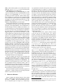
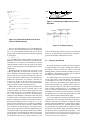
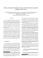
Figure 1 presents the CCM architecture for the example system. The system is realized as a collection of components coupled together via interface and event connections. The system include three modal components (AirFrame, NavSteering, and TacticalSteering) whose behavior changes depending on the mode of the component
(the mode of each component will be represented by an attribute with an appropriate enumeration type). Moreover,
the system is designed to run on a single processor. For this
reason, we refer to the example as ModalSP. Input position
data is gathered periodically at a rate of 20 Hz in the GPS
component and then passed to an intermediate AirFrame
component (which in a more realistic system would take position data from a variety of other sensors). Both the NavSteering and TacticalSteering component produce cue data
for Display based on air frame position data. The Navigator component polls for inputs from the plane navigator at
a rate of 5 Hz and uses those to form NavSteeringPoints
#pragma prefix "cadena"
module modalsp {
interface ReadData {
readonly attribute any data;
};
eventtype TimeOut {};
eventtype DataAvailable {};
enum LazyActiveMode {stale, fresh};
component LazyActive {
provides ReadData dataOut;
uses
ReadData dataIn;
publishes DataAvailable outDataAvailable;
consumes DataAvailable inDataAvailable;
attribute LazyActiveMode dataStatus;
};
enum OnOffMode {enabled, disabled};
interface ChangeMode {
attribute OnOffMode modeVar;
};
component Modal1 {
provides ChangeMode modeChange;
provides ReadData dataOut;
uses
ReadData dataIn;
publishes DataAvailable outDataAvailable;
consumes DataAvailable inDataAvailable;
};
};
Figure 2. CCM/Cadena artifacts for ModalSP
(excerpts)
data. This data is then used to form navigational steering
cues in NavSteering. PilotControl polls for a pilot steering
mode at a rate of 1 Hz and enables or disables NavSteering
and TacticalSteering accordingly.
Figure 2 gives the CCM IDL that defines the component types LazyActive and Modal1 for the AirFrame
and TacticalSteering component instances in Figure 1.
CCM components provide interfaces to clients on ports referred to as facets, and use interfaces provided by other
clients on ports referred to as receptacles. Components
publish events on ports referred to as event sources, and
consume events on ports referred to as event sinks. In the
LazyActive component type of Figure 2, dataOut is
the name of a facet with interface type DataAvailable,
and dataIn is the name of a receptacle with interface
type DataAvailable. Similarly, inDataAvailable
is the name of an event sink of type DataAvailable,
and outDataAvailable is the name of an event source
of type DataAvailable. Components can also have attributes such as modeVar that are used either in component
configuration or to represent some other aspect of component state. For an attribute with name attrname, the IDL
compiler will automatically generate an accessor method
get attrname and a mutator method set attrname. If the
attribute is declared readonly as in the ReadData interface of Figure 2, then only an accessor method is generated2 .
While CCM allows components to be dynamically created and (dis)connected, Bold Stroke applications follow
2 The name of the accessor/mutator methods are dependent on the IDL
to language mapping.
Timer[5]
BM.PushDataSource
BM.Passive
BM.Modal2
Navigator
NavSteeringPoints
NavSteering
disabled enabled
Timer[20]
Interface (Data) Ports
facet (interface provided)
BM.Device
BM.LazyActive
GPS
AirFrame
BM.Display
BM.ModeSource
Display
PilotControl
stale fresh
receptacle (interface used)
Timer[1]
Event Ports
source (event published)
sink (event consumed)
BM.Modal1
Event Correlation
TacticalSteering
and−correlation
enabled disabled
Figure 1. ModalSP – a simple avionics system
system ModalSPScenario {
import cadena.common, cadena.modalsp;
Rates 1, 5, 20;
// Hz rate groups
Locations l1, l2, l3; // abstract deployment locs
...
Instance AirFrame implements LazyActive on #LAloc {
connect this.inDataAvailable
to GPS.outDataAvailable runRate #LArate;
connect this.dataIn to GPS.dataOut;
}
Instance TacticalSteering implements Modal1 on l2 {
connect this.inDataAvailable
to AirFrame.outDataAvailable runRate 5;
connect this.dataIn to AirFrame.dataOut;
}
...
}
Figure 3. Cadena Assembly Description for
ModalSP (excerpts)
typical practice in safety/mission-critical systems and employ a static component allocation and configuration policy
by creating and connecting components only in a system
initialization phase. Dynamic reconfiguration is achieved
by including components whose behavior can be deactivated based on the system mode settings.
The CORBA 3.0 specification does not provide a dedicated language for static system configuration. Cadena provides three languages for describing configurations. Graphical, textual, and forms-based descriptions are synchronized
through a single internal form. Figure 3 displays a fragment of the textual Cadena Assembly Description (CAD)
for the example system. In CAD, a developer declares the
component instances that form a system, along with rate
and distribution annotations. For receptacle and event sink
ports, a connect clause declares a connection between a
port of the current instance and a port of the component
that provides the interface/event. This follows a convention
that connections are declared on the client-side of an interface/event connection. Each event sink port connection uses
the runRate clause to indicate which rate group thread
should run the event handler upon event dispatch. For each
instance, a developer names a location upon which the instance is to be allocated. Location names are not bound to
physical locations at this point in the process, but will subsequently be mapped to CORBA specific notions such as
containers and nodes at deployment time.
Incomplete specifications and incremental construction
are supported by allowing rate and location variables such
as #LAloc and #LArate. These act as place holders, and
values for these can be inferred using the non-functional
aspect synthesis algorithms presented later. Equality constraints between such variables can also be specified, and
the synthesis procedures generate output that conforms to
these constraints. A type-checking procedure ensures welltyped connections.
Bold Stroke applications follow a control-push data-pull
architecture in which data is transferred between data producer and data consumer components in a two step process.
First, a data producer (e.g., TacticalSteering) publishes
a DataAvailable event indicating that it has updated
some data that is ready to be consumed. Then, when a subscribing data consumer (e.g., Display) receives the event,
it calls a get data accessor method in a facet provided by
the supplier to retrieve the data. Thus, threads never block
waiting for data to become available, and this simplifies the
design of real-time aspects. Under this strategy, component
connections come in pairs consisting of an event connection
for notification that data is ready, and an interface connection for fetching the data.
The LazyActive component type of Figure 2 implements a variant of this strategy to handle situations where
a component C (e.g., AirFrame) depends on data that is
updated much more frequently than C’s clients require C’s
data. For example, the AirFrame component does not fetch
data immediately from GPS when notified, but instead simply sets its dataStatus attribute to indicate that its data
is stale and notifies its clients (e.g., TacticalSteering) that
its data is available. When a get data call for AirFrame data
comes from one of its clients, it checks the dataStatus
attribute to see if its data is fresh, and if it is, it returns it immediately to the calling client. If it is not fresh, it calls the
GPS get data method, updates its own data with the return
GPS data, sets its dataStatus to fresh, and returns the
new AirFrame data to the calling client.
Both NavSteering and TacticalSteering are modal
components that have two modes (enabled,disabled). These
modes are set by PilotControl via ChangeMode facets
provided by the modal components. When a modal component is disabled, any events received are simply discarded
by the component. When enabled, the component responds
according to the control-push data-pull strategy (e.g., TacticalSteering responds to a DataAvailable from AirFrame by calling AirFrame’s get data method.
In Bold Stroke applications, even though at a conceptual
level component event source ports are connected to event
sink ports, in the implementation, event communication is
factored through a real-time CORBA event channel. Use
of such infrastructure is central to Bold Stroke computation
because it provides not only a mechanism for communicating events, but also a pool-based threading model, timetriggered periodic events, and event correlation. In order
to shield application components from the physical aspects
of the system, for product-line flexibility, and for run-time
efficiency, all components are passive – component methods are run by event-channel threads that dispatch events
by calling the event handlers (“push methods” in CORBA
terminology) associated with event sink ports. The roots
of computation are time-triggered events (e.g., events associated with event sinks of Navigator, GPS, and PilotControl) supplied at a specified rates by the event-channel.
Dispatching of these events causes the dispatch threads to
run the associated handlers which contain methods calls and
publishing of subsequent events. In the current Bold Stroke
implementation, the event channel thread pool has exactly
one thread associated with each rate. As noted earlier in the
discussion of Figure 3, each non-time-triggered event port
also has a rate specified at configuration time which indicates its rate group, i.e., the pool thread that should run the
event handler when the event is dispatched.
The event channel also provides event correlation and
event filtering mechanisms. In the example system, andcorrelation is used, for instance, to combine event flows
from NavSteering and AirFrame into NavDisplay. The
semantics of and-correlation on two events e1 and e2 is that
the event channel waits for an instance of both e1 and e2 to
be published before creating a notification event that is dispatched to the consumer of the correlation. The semantics
of a correlator is defined by an automaton over event traces
derived from the correlation expression [22].
Note that CCM IDL captures the interface properties of
components – Cadena’s notation for expressing component
behavior is presented in the next section.
3
Cadena Architecture
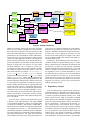
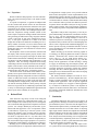
Figure 4 displays the internal structure of the Cadena
toolset. Cadena projects contain four high-level specification forms: a CORBA 3 IDL file that defines the structure of component types (see Figure 2), a Cadena Prop-
erty Specification (CPS) file that specifies various aspects
of component behavior (see Figure 5), a Cadena Assembly
Description (CAD) that specifies the components instances
that form the system, the connections between them, along
with other real-time and distribution property information
(see Figure 3), and a specification file that stores information about the desired correctness properties of the system.
These input artifacts are created using customized editors
built using Eclipse plug-in facilities. In particular, the CAD
format has a textual editor, a graphical editor (to view systems as graphs similar to style of Figure 1)3 , and a formbased editor that allows one to easily define different projections of the component assembly (e.g., connections only,
distribution and rate assignments only, etc.). The graph
structure described by the CAD is the basic data structure
that is used by the dependency analyzer (discussed in Section 4), the graphical view displayer, and the deployment
code generator (which generates Java code to allocate and
connect components).
Dependence Specifications: Figure 5 displays excerpts
of the CPS file for our example system. In a CPS description, developers may declare intracomponent dependencies between ports and simple behavioral descriptions of
a component’s event handlers and other methods. The dependence declarations take the form trigger-port-action ->
response-port-action. For example, Figure 5 declares that
consumption of an event on the inDataAvailable port
of a LazyActive component may trigger a publish on the
outDataAvailable port in both stale and fresh
modes. The absence of a dependence for the dataOut port
in the fresh mode indicates that any call on dataOut
should not result in an action on any other port.
A dependencydefault may have one of two settings: a none setting allows developers to start with an
empty dependence relation and add new dependencies (i.e.,
dependences do not exist except when declared), an all
setting allows developers to start with a universal dependence relation and then prune dependences (i.e., by default
all possible dependencies between ports exist). In the all
setting, once a port is mentioned on the left-hand-side, then
only declared dependences apply for that port. For example, for Modal1 which has the all setting, the absence
of declarations for the dataOut port specifies that the
ports (outDataAvailable and dataIn) do depend on
dataOut (note that is an overapproximation of the actual
behavior). Dependencies are pruned in Modal1 by giving
refining declarations such as those for the modeChange
and inDataAvailable ports that list no dependents to
the right of the ->.
Behavioral Specifications: Since transition systems for
model-checking are generated from behavioral descriptions, their primary purpose is to capture (a) the actions
that one wishes to reason about in temporal specifications
and (b) simple control-flow relationships between these actions. Cadena supports observable actions such as event
3 We do not use an actual screen shot for Figure 1 because the current
version of Eclipse does not include zoom in/out capabilities, and the current layout is too large to fit on a screen.
OpenCCM
IR3
.idl3
Graphical
View
Textual
View
.cps
Editor
.cad
CAD Compiler
Dependency
Analyzer
.spec
Non−Functional
Aspects
Synthesizer
Deployment
Generator
Property
Editor
Stubs
(.java)
IDL2Java
Visualization
Skeletons
(.java)
Implementation
(.java)
System Assembly
(.java)
Form
View
TimeEdit
Model
Generator
DSpin
model
DSpin
Figure 4. Cadena architecture
publish and consume, method call and return, data flows
between system variables, assignments to mode variables.
Each behavioral description in the CPS format gives both
a data and control abstraction of a component’s actual implementation of an event handler or method. Data abstraction is achieved by only exposing concrete values of mode
variables (or other application variables with bounded domains). This was motivated by the fact that Bold Stroke engineers are primarily concerned with reasoning about modal
behavior at design time since analysis of system modes
and mode transitions can be leveraged in several ways.
Even though concrete values of other application variables
are usually not modeled, data flows between such variables can be captured. For example, internalData <dataIn.get data(); in the LazyActive behavior
models a flow from the result of the get data(); method
into the internalData variable. This may abstract many
actual computation steps in the actual implementation. The
behavioral language contains simple control structures such
as sequencing and conditionals and abstracts control by
simply omitting commands from the implementation that
one does not wish to observe. Note that dependence information can also be derived from behavioral specifications,
and this provides a form of checkable redundancy. The intent is that developers begin with the more light-weight dependence specifications, leverage those, then only incorporate behavioral specifications when model-checking analysis is to be applied.
Code Generation: Cadena uses the OpenCCM tools [12]
to generate system implementations. The OMG CORBA
3.0 specification standardizes a strategy for compiling IDL
(of which the CCM IDL is part) down to CORBA IDL 2,
which can then be translated to an underlying implementation language such as Java or C++. This translation process
automatically generates a substantial amount of infrastructure code for tasks such as component creation and connecting and disconnecting ports. The output code contains the
usual CORBA stubs and skeletons, along with skeleton im-
plementations of component methods and event handlers.
With this code generation, the developer only needs to implement event handlers and methods on provided interfaces.
In future work we are exploring the extension of CCMbased code generation strategies to integrate code generation for component handler state-machines and global synchronization policies [8].
Methodology: When building systems with Cadena, we
intend for developers to take the following steps: (1) load a
library of domain-specific components and associated CPS
specifications, (2) define new project-specific components
and associated behavioral CPS specifications, (3) use CAD
editors to configure connections between components, (4)
use dependency viewer to examine dependencies, (5) use
non-functional aspect synthesis tools to attach distribution
and rate information (see Section 4.3), (6) specify desired
global correctness properties (see Section 5.5), (7) generate a transition system model and model-check correctness
properties (see Section 5), and (8) revise system based on
feedback from analysis tools.
4
Dependency Analysis
Even with small systems of around 20-30 components,
relationships between components and component dependences are often hard to determine from visual inspections
of textual or graphical component assembly views. Bold
Stroke systems can have 1000s of components, and Bold
Stroke engineers have identified development of automated
support for component dependency analysis and visualization as a high priority. As discussed in the previous section, Cadena provides several different layers of dependency specification and analysis with the goal of enabling
incremental construction of dependency specifications – little or no specification effort should still allow useful tool
feedback since a fair amount of dependency information
(inter-component dependences) can be derived from the
CAD information. Increasing the details of specifications
component LazyActive {
mode dataStatus;
dependencydefault == none;
dependencies {
case dataStatus of {
stale: inDataAvailable -> outDataAvailable;
dataOut.get_data(); -> dataIn.get_data();
fresh: inDataAvailable -> outDataAvailable;
}
}
behavior {
any internalData;
dataAvailable.push(_) {
if (dataStatus == fresh)
dataStatus = stale;
outDataAvailable.push(_);
}
any dataOut.getData() {
if (dataStatus == stale) {
internalData <- dataIn.get_data();
dataStatus = fresh;
}
return internalData;
}
}
}
component Device {
behavior { ... }
}
component Modal1 {
mode modeChange.modeVar;
dependencydefault == all;
dependencies {
modeChange ->;
case modeChange.modeVar of {
enabled: inDataAvailable
-> dataIn.get_data(),
outDataAvailable;
disabled: inDataAvailable ->;
}
}
behavior { ...
}
}
Figure 5. Cadena Property Specification
(CPS) (excerpts)
should yield more precise visualizations and analysis. Here
are the steps that we expect developers to take when creating and refining dependence information: (1) give component assembly without CPS dependence information using the global dependence default that all actions on input
ports of a component C give rise to actions on all output
ports of C, (2) refine by giving dependences without taking into account modal behavior, (3) refine by considering
modes in CPS dependence declarations, and (4) refine by
giving behavioral descriptions (which capture dependence
information via control-flow properties). Bold Stroke developers currently use dependency information manually to
determine non-functional aspects such as distribution, connection implementation (synchronous vs. non-synchronous
calls), rate group assignment, etc. Cadena leverages partial
dependence information to provide automated support for
developers.
4.1
Basic notions of dependency
Given a component library and component assembly description (along with optional Cadena property specification
file), Cadena’s port-level dependency module builds a port
dependence graph PDG = (N,E) where each node n ∈ N
is a component/port pair i.p. Edges (i.e., dependences) between PDG nodes arise from two sources: inter-component
dependences corresponding to port connections specified
in component assembly descriptions and intra-component
dependences captured by CPS declarations in component
property specifications. Whether or not intra-component
dependences are generated for a particular instance C depends on the default dependence setting for C as discussed
previously. The default setting is given by the global default dependence declaration unless a component-local default declaration exists.
For inter-component dependences, when there is a connection between i1 .p1 and i2 .p2 in the component assembly
description, we say that i1 .p1 is event dependent on i2 .p2
e
(written i2 .p2 → i1 .p1 – the arrow pointing in the direction of the event flow) if p2 (resp. p1 ) is an event source
(resp. sink). Similarly, with the above connection, i1 .p1 is
n
interface dependent on i2 .p2 (written i2 .p2 → i1 .p1 ) when
p2 (resp. p1 ) is a facet (resp. receptacle). For example,
from the CAD information in Figures 1 and 3, we have, e.g.,
e
GPS.outDataAvailable → AirFrame.inDataAvailable
n
and GPS.dataOut → AirFrame.dataIn.
For intra-component dependences, for an instance i of
component type c, i.p1 is trigger dependent on i.p2 (written
t
i.p2 → i.p1 ) when either (1) p2 is declared to trigger p1
in the CPS for c, or (2) the default dependency status for
c is all and there exists no trigger declaration for p2 in the
Cadena specification for c.
As with conventional work on dependences, a system
slice for a particular point(s) of interest (referred to as the
slicing criterion) is computed by taking the transitive closure of the PDG from the PDG node(s) corresponding to
the slicing criterion. Basic slicing actions provided by Cadena include forward slice, backward slice, and slice intersections.
4.2
Mode-aware dependences
To reason about mode-aware dependences, the mode
state of the system is captured formally via a mode-state
vector m which holds values for one or more mode variables
from the system being analyzed. In the ModalSP scenario,
it is useful to consider a two-variable mode-state vector that
holds the mode state of NavSteering and the mode state
of TacticalSteering. Given a PDG P = (N, E) for a system, a modal PDG Pm = (Nm , Em ) for mode-state vector
m is formed by setting Nm = N and having Em include
all inter-component edges, but only intra-component edges
that are enabled according to m.
Cadena provides mechanisms for collecting a set of
mode-state vectors and using these to drive visualization
of dependences (i.e., Cadena users can choose to visual-
ize dependences for a particular vector). Mode-state vector
sets can be entered explicitly in a form-based view or generated automatically from the state-exploration techniques
discussed in the following section. For instance, for the
mode-vector mentioned above, it is instructive to have a
mode-based dependency view for the three mode-state vectors (disabled, disabled), (enabled, disabled), and (disabled,enabled).
4.3
Dependency-driven analyses
In the Bold Stroke development process, several nonfunctional system aspects that are currently designed manually can be aided or even synthesized automatically using the dependence analysis capabilities described above.
These include (following the order in which they are carried out) assigning priorities/execution-rates to event consumer ports, appropriately distributing component instances
to network nodes, and identifying opportunities for switching asynchronous remote event delivery (the default mechanism) to synchronous local method calls.
Rate Assignment: Automated rate assignment begins by
assigning rates to each event consumer port that subscribes
to a time-triggered event – the port simply is assigned the
rate of the event. Using the results of the dependency analysis above, the process continues by propagating rate information along the PDG in a forwards direction and assigning the propagated rate value to each input and output
port encountered. In cases where a port has more than one
rate propagated to it (e.g., when event correlation is used, or
when two different input ports influence an output port), the
highest of the rates is propagated. The process continues
until a fixpoint is reached and the resulting rates on event
consumer ports bind CAD rate variables.
In the example in Figure 1, automated rate assignment
would result in assigning 1Hz to the event consumer of
PilotControl, and to the receptacles of PilotControl and
the facets of TacticalSteering and NavSteering connected
to PilotControl. Similarly, (a) all ports in Navigator,
NavSteeringPoints are assigned 5Hz, and the two ports of
NavSteering connected to NavSteering are assigned 5Hz,
and (b) all ports in GPS and AirFrame are assigned 20Hz.
There is now a conflict for the rates on the output ports of
NavSteering due to the fact both 5Hz and 20Hz rates are
flowing in, so the higher rate of 20Hz is used. The process
continues until the remainder of the unassigned ports have
a value of 20Hz.
Distribution Determination: The distribution algorithm
then uses the rate information gathered above (a) to determine the traffic on the connections between components,
and (b) to identify components to be deployed on a common
location. In the example, the algorithm would group components closer to their trigger source with the traffic and rate
information used as the arbitrating criteria.
In the example, Navigator and PilotControl would be
assigned distinct locations, l1 and l2. The rest of the
components would be assigned location l3 as the traffic between them is higher assuming all data and event types are
of unit size. However, if the traffic on the data connection
between Navigator and NavSteeringPoints was higher
than the cumulative traffic on other connections on NavSteeringPoints then NavSteeringPoints would be assigned
location l1. Although this simplistic example is not realistic, the ability to automatically leverage connection and
rate information to provide developers with guidance about
component distribution can be a significant advantage for
large systems.
Synchronous Dispatch Optimization: For the reduction
of asynchronous remote event deliveries, an event delivery between two component instance ports i1 .p1 and i2 .p2
that does not involve correlation can be reduced to a local
method call when i1 and i2 are co-located and when the
rates attached to p1 and p2 through the propagation above
are the same. In the example, this optimization can be applied to all non-correlated event connections. However, if
NavSteeringPoints and NavSteering were assigned different locations in the distribution step above, the optimization would not apply to that connection.
Finally, although we do not implement schedulability
analysis in Cadena, we note that Cadena’s dependency
specifications (in particular, mode-aware dependence information) can be used to improve static scheduling. Currently, static schedulability analysis in Bold Stroke is based
on summing execution costs along call-tree paths deduced
from component connections only (i.e., our all dependence mode with no declared dependences). Cadena specifications prune away many infeasible dependences, and
therefore prune away infeasible paths that may cause worstcase execution time estimates to be more conservative than
necessary. This can sometimes save a surprising amount
of development time since systems are often restructured in
significant ways to obtain schedulable computations.
5
Model-checking Designs
As illustrated in the previous section, light-weight dependence analyses can provide a wealth of information
about relationships among design components. In addition
to this, Cadena supports deeper semantic analysis of design behavior using model checking. Specifically, we support reasoning about logical properties of component-based
designs expressed as assertions, invariants and sequencing
properties over system states and actions, such as method
calls and returns and event publications and consumptions.
In order to maximize the flexibility of Cadena in targeting different classes of component-based systems, we have
designed a layered translation from our extended CCMbased specification languages to the input language of the
DSpin [7] model checker. The translation includes modeling of: (i) component interfaces and behavior, (ii) the
semantics of middleware components through which component execution is orchestrated, and (iii) event and data
sources and sinks in the system environment. These translation aspects have well defined interfaces that make it easy
to vary, for example, the semantics of middleware functions
to suit a particular application domain. In the remainder of
this section, we discuss each of these aspects in turn as well
as our approach to specifying the properties to be checked.
Unlike much of the existing work in model checking system
designs, we found it necessary to exploit knowledge of the
middleware and environment to achieve models that were
compact enough to check in a reasonable amount of time.
We describe how we abstracted domain knowledge for the
Bold Stroke architecture to encode it into our models. We
conclude with a discussion of our experiences model checking properties of several variations of models generated for
the design from Figure 1.
5.1
Why DSpin?
Cadena uses DSpin as its model checking engine. In
principle we could use any one of a number of available
model checking tools, such as Spin [14] or NuSMV [2],
however, component-based designs have a number of features that are difficult to express in the low-level input languages of such tools. For example, one needs to be able
to define an object, i.e., a collection of data attributes, manipulate references to an object, and invoke the methods associated with an object. It is clearly possible to map such
high-level constructs onto a model checker input language
as JPF [13] and Bandera [4] do, but it is much easier when
the model checker supports those constructs directly. DSpin
is an extension to Spin that adds support for objects, functions, and references, among other features. DSpin is implemented in such a way that it runs as least as fast as Spin for
the functionality they have in common [7] and our experience is that the performance penalty for using the extensions
is minimal when compared to hand-optimized models.
5.2
Component Modeling
Translating Cadena components is straightforward. A
component is implemented as a group of state variables, for
attributes and modes, and DSpin function references, for the
receptacle methods consumed from other components. Associated with each component are a group of functions that
implement the event consumer methods (i.e., handlers) and
methods provided by the component.
There are two advantages to this translation: it has a
natural mapping back to the Cadena model which facilitates expressing diagnostic information about detected errors and it decouples the component from other components
so that models can be easily reconfigured. For example,
the NavSteering component, shown in Figure 6, does
not encode the identity of source1 from which it reads
dataIn1. Rather, the component has a function reference
that is assigned to the appropriate method reference based
on configuration information. We have generated models
with static configurations to date, but it is trivial to support
dynamic reconfiguration.
5.3
Modeling Middleware Services
CCM systems assume the presence of middleware services such as an event-channel with a pool for dispatching
any NavSteering_internalData;
mode NavSteering_componentState;
ftype Ref_NavSteering_dataIn1_getData,
Ref_NavSteering_dataIn2_getData;
ftype Ref_NavSteering_update;
function Fun_NavSteering_source1 (mtype t) {
printf("NavSteering: source1 handler invoked.\n");
if
:: NavSteering_componentState == enabled ->
NavSteering_internalData =
Ref_NavSteering_dataIn1_getData ();
printf("NavSteering: publishing update.\n");
Ref_NavSteering_update (NavSteering_DataAvailable)
:: else
fi
}
function Fun_NavSteering_switch_getData () : int {
atomic {
P <= 1 ->
printf("NavSteering: switch getData invoked.\n");
P = MaxPriority
}
return NavSteering_componentState;
}
Figure 6. DSpin model for NavSteering Modal
Component (excerpts)
proctype RateGroup_1Hz () {
ftype f;
mtype m;
...
do
:: skip ->
S_timeout?b;
...
do
:: Rate1_queue?[f, m] -> Rate1_queue?f(m); f(m)
:: else -> break
od
od
}
Figure 7. DSpin model of Event Channel Ratespecific Thread
threads to execute component code.
Modeling Event Services: In our DSpin models an event
publication is achieved by sending the function reference
for the component’s event handler and the identity of the
event as a message to the process modeling the eventchannel thread. That thread then invokes the event handler
code for the component instance as illustrated in Figure 7,
where ftype is a DSpin function reference and mtype is
an enumeration encoding the events in the system.
It is easy to identify pairs of component instances where
one publishes an event that is consumed by the second. Under certain constraints the behavior of those components
may be sequenced, for example when they have the same
rate assignments in a Bold Stroke application. Under these
conditions, the generic function-event pair queuing mechanism described above may be replaced by direct calls
from the component instance publishing the event to the
handlers for component instances subscribed to that event.
For example, all publications of dataAvailable events from
function Proxy_NavSteering_update (mtype t) {
int i = 0;
printf("NavSteering-Proxy: Calling subscriber methods.\n");
do
:: i < NavSteering_update_NumberSubscribers ->
NavSteering_update_SubscriberList[i].Entry(t);
i = i + 1
:: else -> break
od
}
active proctype PriorityHandler () {
do
:: timeout ->
d_step {
if
:: P > 0 -> P = P - 1;
:: else
fi
}
od
}
Figure 8. DSpin Model of intra-Rate-Group
Push Proxy
Figure 9. Rate Selection Process
tion it is modeled as the separate process shown in Figure 9.
the NavSteering component are made by calling the
Ref NavSteering update function reference which is
bound to the function in Figure 8. Sequencing execution
of event publications and consumer code yields a smaller
state space 4 by reducing the data states associated with the
thread queues, e.g., Rate1 queue.
Each event correlation in the system has its own DSpin
function. This function is generated based on the automaton that defines the meaning of the correlation expression
[22]. The correlation function acts as a handler for its input
events, updates the state of the automaton, and when an accepting state is reached it publishes the correlated event to
subscribers using the same mechanisms as described above.
Since the correlation functionality is internal to the middleware service its internal steps are unobservable to the application, thus we model them as atomic transitions.
Modeling Thread Services: Middleware provides the
threads on which application components execute, and it
may also define a scheduling policy for those threads. When
such a policy is available it can be exploited to reduce the
state space of the generated model by eliminating interleavings of thread executions that violate the scheduling policy. Eliminating such interleavings also has the beneficial
effect of improving the precision of analysis performed on
the model.
Bold Stroke applications use rate monotonic scheduling
[16] for event-channel threads. Rate monotonic scheduling is a pre-emptive priority based scheduling policy where
higher rates are assigned higher priorities. Like most model
checkers, DSpin does not support the definition of a specific
scheduling policy, so we encode the policy directly in the
DSpin model. This is achieved by guarding all component
actions with a test that blocks the action if the component’s
priority is less than the current runnable priority, which is
stored in a global variable P . The print statement of function Fun NavSteering switch getData in Figure 6
illustrates such a guard. Guarded component actions are
only enabled when the current runnable priority has been
decremented to the component’s priority. A decrement is
performed only when there are no enabled steps in the
model which can be detected by the timeout predicate of
Spin. Since this priority decrementing process must operate
independent of component or event-channel thread execu4 A similar event-channel performance optimization is applied quite frequently in Bold Stroke applications.
The resulting model has several interesting properties.
It assures that the highest-priority runnable action will be
performed; this yields a dramatic reduction in the system
state space as discussed below. Note that components running at the highest system wide priority need not have their
actions guarded. This, combined with the direct call modeling of event publication and handling, means that highpriority behavior effectively executes as a single atomic step
in the model. The introduction of an explicit global priority does add a state variable to the system, but note that it
only changes value when no other transitions in the model
are enabled. Consequently, there are no possible interleavings of the different priority values with component/thread
execution and the effect on the state space is trivial.
5.4
Environment Modeling
Cadena models capture the combined behavior of a collection of component instances working in concert to respond to external inputs and to produce appropriate outputs.
We use the term environment to describe the entities that
interact with the explicitly modeled system. Since Cadena
models do not attempt to accurately model data values flowing between the environment and the system the only relevant inputs are environment initiated events. The semantics
of those events and the pattern of event arrival at the system
will vary with each application.
Our experience suggests that accurate modeling of environment initiated events is necessary both for precision in
reasoning and for state space reduction. The Cadena tools
have builtin support for generating environment models for
Bold Stroke system designs. These systems are driven by
periodic events generated by the middleware. The rates
of these events are typically harmonic to enable reasoning
about schedulability via rate monotonic analysis.
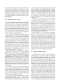
Our generated transition system models do not represent
time explicitly, rather they constrain the number of timeout
event publishes for a given rate relative to timeout publishes
for its adjacent rates. For example, in the interval defined
by a pair of 5 Hz timeout events there must be four 20 Hz
timeouts. Constraining the timeout events appropriately is
achieved by including a separate Timer process in the transition system that keeps track of an abstraction of time and
triggers timeout events appropriately.
proctype Timer () {
int t = 0;
do
:: (t >= 6) -> t = 0
:: (t < 6) ->
if
:: (t % 2) == 0 -> S_timeout15!1
:: else
fi;
if
:: (t % 3) == 0 -> S_timeout10!1
:: else
fi;
if
:: (t % 6) == 0 -> S_timeout5!1
:: else
fi;
t = t + 1
od;
}
20 hz
B
A
C
5 hz
Figure 11. Interleaving of Rate Group Thread
Execution
Figure 10. Timeout Generation Process for 5,
10 and 15 Hz Rate Groups
Figure 12. Timeline property
For a system with harmonic rates, one could simply keep
a counter, t, that is incremented from 0 up to the maximum
rate, m, by one to maintain an abstract time. For a k Hz rate
group, initiation of the timeout event would then be guarded
by testing that:
t % m/k == 0
m/k is guaranteed to be a whole number since the rates are
harmonic. If the rates are not harmonic, then instead of the
maximum rate, the counter is incremented up to the least
common multiple (LCM) of the rate groups in the system
and the rate specific guards use LCM rather than m in their
modulo tests.
Depending on the exact rates used in a system we can
reduce the granularity of abstract time and achieve a state
space reduction by reducing the number of values that t will
take on. To do this we scale the LCM and each of the rates
down by their greatest common factor (GCF) and adjust the
modulo tests appropriately. For example, if the rates in a
system are 5, 10 and 15, then the LCM is 30, the GCF is
5, and we increment t from 1 up to 6. The generated timer
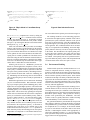
process for such a system is shown in Figure 10.
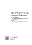
Rather than use the event publication mechanisms described in the previous section, for timeout events we use
rendezvous channels to couple the timer and the processes
that model rate-specific event channel threads (see Figure 7). The rate-specific processes force all processing of
published events handled by components in that rate group
to complete before executing the rendezvous with the timer.
Figure 11 illustrates the possible behaviors that can arise in
the generated transition system as a result of Timer’s behavior and the enforcement of rate monotonic scheduling.
Processing in each rate group is forced to complete before
the next timeout for that rate group. Processing in lowerpriority rate groups can occur only after higher-priority processing has completed. No attempt is made in the transition
system, however, to ensure that the amount of lower-priority
processing that occurs is appropriate, either by restricting
the amount that can occur (e.g., region A in Figure 11 per-
forms an infeasibly large amount of work) or by forcing it to
occur (e.g., the region between regions B and C in Figure 11
performs an infeasibly small amount of work).
5.5
Property Specification
We divide the problem of stating correctness properties
of Cadena designs into two parts: defining observations of
the behavior of the system that one wishes to make and
defining patterns of observations that constitute correct system behavior. Our approach is similar to the one taken in
the Bandera Specification Language [5].
In Cadena designs user’s may wish to reason about the
call or return from a component method, the publication
or consumption of an event, or the values of component
modes. These basic observations can be qualified by component instance identity (e.g., a method call to a specific instance), parameter values (e.g., the return of a specific value
from a method), component ports (e.g., the handling of an
event on a specific component port), or rate groups (e.g.,
publishing an event from a specific rate group). The syntax
for defining these observables mirrors the syntax of CCM
and the Cadena extensions defined in this paper.
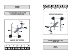
User’s can instantiate an existing set of property specification patterns [10] with Cadena observables to form specifications of desired system behavior. In addition, Cadena
generates observable definitions in a format that is compatible with the Timeedit tool [23]. Timeedit supports graphical specification of properties that are made up of complex chains of observations. Figure 12 illustrates a Timeedit
specification for the constrained response property: “when
a 20 Hz timeout occurs and navigation steering mode is enabled, the display will be updated by the navigation component and not the tactical component”.
5.6
Experience
We have model checked properties of several Cadena designs. The most interesting of these is the modal scenario
of Figure 1.
As a point of comparison, we generated a DSpin model
for this scenario that did not enforce the rate-monotonic
scheduling policy and performed an exhaustive state-space
exploration for the number of timeouts issued in a single
second of system execution. We ran DSpin using the maximal state compression settings available (which are the
same as Spin’s compression settings) and the check aborted
after generating 26 million states using 1 Gigabyte of RAM.
Clearly, some form of state space reduction was necessary. A state-space exploration on a model of the same
design that encoded rate-monotonic scheduling for an arbitrary number of timeouts, ran in less than a minute and
generated 1.4 million states using 130 Megabytes of RAM.
Similar state space sizes were found for all of our checks on
the modal scenario.
We attempted to check several assertions, invariants and
the display mode related response property shown in the
previous section. The property from Figure 12 failed on the
model with non-deterministic scheduling due to the fact that
execution of a 20 Hz component was preempted by a 1 Hz
component. Thus, the steering component mode settings
could change after the 20 Hz timeout and before the display
update occurred. This is clearly infeasible in the actual system and performing the check on the rate-monotonic model
described above bore that out by verifying the property.
The modal scenario is unrealistic in the number of components, but it is quite realistic in the number of rate groups.
Recall that high-priority component execution is effectively
atomic in models that encode rate-monotonic scheduling.
This suggests that the rate of growth of the state space with
increasing numbers of high-priority components will be linear whereas increasing numbers of lower-priority will yield
faster rates of growth. We are conducting experiments with
a variety of Cadena designs of Bold Stroke applications and
plan to report on the scalability of our approach.
6
be integrated into a single system. User’s provide sufficient
detail in these descriptions to allow implementations to be
automatically generated. Ptolemy provides a run-time infrastructure to mediate between components that have different
execution models. In contrast, Cadena models intentionally
leave out detail in order to provide more abstract system descriptions that are amenable to analysis for large systems.
While Cadena provides some code generation capabilities,
we do attempt to generate component method implementations.
Dependence analysis has a long history of uses in program understanding, transformation, maintenance and testing (e.g., [15]). Our use of dependence analyses is essentially an adaptation of existing techniques to the level of
abstraction present in CCM designs. Unlike most program
dependence analyses which work from a fixed language definition, we have engineered the annotation languages in Cadena to provide a layering of detail that will allow for more
precise dependences to be calculated and exploited for improved user feedback.
Model checking [3] has become extremely popular as
a technology for analyzing behavioral models of software
artifacts. Researchers have extracted such models from
source code (e.g., [13, 4]), UML design artifacts (e.g.,
[19, 17]) and architectural descriptions (e.g., [1]). The difficulty with all applications of model checking is scaling
it to apply to realistically large and complex systems. Recent years have seen an enormous amount of research on the
systematic abstraction of models to enable more tractable
reasoning. We take a different approach in Cadena by exploiting the natural abstractions that arise when developing
high-level design models of systems.
Our model extraction techniques are based on our experiences with Bandera [4]. We have adapted those techniques to exploit knowledge of the execution environment
of Bold Stroke applications. This can provide significant
state space reduction, but, in support of broad applicability of Cadena to CCM-based systems it was important to
engineer the model extraction framework to accommodate
the semantics of different middleware infrastructures in the
spirit of Garlan [11].
Related Work
7
There has been a large body of work on on timing and
schedulability analysis for component-based systems. As
these techniques have matured, they have been integrated
into environments that support the development of real-time
systems. For example, MetaH [24] and Geodesic [6] are
frameworks that support the reuse of components written
in Ada and Java, respectively, in real-time systems. These
frameworks include a range of timing analyses and automatically generate infrastructure code that coordinates the
execution of component code in a way that achieves the
system’s timing requirements. Cadena is complementary to
this work in that it targets logical properties of a system using both light-weight and heavy-weight analysis techniques.
Ptolemy [18] is a framework that allows a wide variety
of formal descriptions of components and their behavior to
Conclusion
Component frameworks have proven to be effective in
dealing with the challenges associated with building complex distributed systems. We believe that the high-level architectural descriptions used by CCM and other component
oriented frameworks are an excellent vehicle for injecting
light-weight formal methods and sophisticated automated
analysis techniques across the entire software development
process. In particular, we have built Cadena to explore how
static analysis and model-checking can be integrated into
CCM development by capitalizing on the use of CCM IDL
to define what are, in effect, system abstractions that make
such checking feasible for realistic systems.
We have applied Cadena to small and simple avionics systems based on the Boeing Bold Stroke architecture,
and the initial results are encouraging. We believe that
the strategies that we have developed for modeling middleware event services can scale reasonably well to larger
systems. However, for systems with 1000s of components
as one would find in product-line applications, we plan to
investigate the use of compositional checking. In addition,
there are many other forms of analysis needed for developing product-line avionics applications; Cadena current focuses on dependence analysis and behavioral analysis using
model-checking techniques.
Concerning the tool itself, we believe building Cadena
as a plug-in to IBM’s Eclipse using the OpenCCM tools
can provide a tool environment robust enough to experiment
with designs of real systems. More information about the
tool (with example artifacts and screen shots) can be found
at www.cis.ksu.edu/santos/cadena.
References
[12] GOAL. The OpenCCM platform. http://corbaweb.
lifl.fr/OpenCCM/, 2002.
[13] K. Havelund and T. Pressburger. Model checking Java programs using Java PathFinder. International Journal on Software Tools for Technology Transfer, 1999.
[14] G. J. Holzmann. The model checker SPIN. IEEE Transactions on Software Engineering, 23(5):279–294, May 1997.
[15] S. Horwitz and T. Reps. The use of program dependence
graphs in software engineering. In Proceedings of the 14th
international conference on Software engineering, pages
392–411. ACM Press, 1992.
[16] M. H. Klein, T. Ralya, B. Pollak, and R. Obenza. A Practitioner’s Handbook for Real-Time Analysis: Guide to Rate
Monotonic Analysis for Real-Time Systems. Kluwer Academic Publishers, 1993.
[17] D. Latella, I. Majzik, and M. Massink. Automatic verification of a behavioural subset of UML statechart diagrams using the SPIN model-checker. Formal Aspects of Computing,
11(6):637–664, 1999.
[1] R. Allen and D. Garlan. A formal basis for architectural connection. ACM Transactions on Software Engineering and
Methodology, July 1997.
[18] E. A. Lee. Overview of the ptolemy project. Technical Report UCB/ERL M01/11, University of California, Berkeley,
Mar. 2001.
[2] A. Cimatti, E. Clarke, F. Giunchiglia, and M. Roveri.
NuSMV : a new symbolic model checker.
International Journal on Software Tools for Technology Transfer,
2(4):410–425, 2000.
[19] J. Lilius and I. P. Paltor. vUML: A tool for verifying UML
models. In Proceedings of the 14th IEEE International Conference on Automated Software Engineering, 1999.
[3] E. Clarke, O. Grumberg, and D. Peled. Model Checking.
MIT Press, 2000.
[4] J. C. Corbett, M. B. Dwyer, J. Hatcliff, S. Laubach, C. S.
Păsăreanu, Robby, and H. Zheng. Bandera : Extracting
finite-state models from Java source code. In Proceedings
of the 22nd International Conference on Software Engineering, June 2000.
[5] J. C. Corbett, M. B. Dwyer, J. Hatcliff, and Robby. A language framework for expressing checkable properties of dynamic software. In Proceedings of the SPIN Software Model
Checking Workshop, volume 1885 of Lecture Notes in Computer Science, Aug. 2000.
[6] D. de Niz and R. Rajkumar. Geodesic - a reusable component framework for embedded real-time systems. Technical
report, Carnegie Mellon University, 2002.
[7] C. Demartini, R. Iosif, and R. Sisto. dspin : A dynamic
extension of SPIN. In Theoretical and Applied Aspects of
SPIN Model Checking (LNCS 1680), Sept. 1999.
[8] X. Deng, M. B. Dwyer, J. Hatcliff, and M. Mizuno.
Invariant-based specification, synthesis and verification of
synchronization in concurrent programs. In Proceedings of
the 24th International Conference on Software Engineering,
May 2002.
[9] B. Doerr and D. Sharp. Freeing product line architectures
from execution dependencies. In Proceedings of the Software
Technology Conference, May 1999.
[10] M. Dwyer, G. Avrunin, and J. Corbett. Patterns in property
specifications for finite-state verification. In Proceedings of
the 21st International Conference on Software Engineering,
May 1999.
[11] D. Garlan and S. Khersonsky. Model checking implicitinvocation systems. In Proceedings of the 10th International
Workshop on Software Specification and Design, Nov. 2000.
[20] D. Sharp. Reducing avionics software cost through component based product line development. In Proceedings of the
Software Technology Conference, Apr. 1998.
[21] D. Sharp. Object oriented avionics software flow policies. In
Proceedings of the 18th AIAA/IEEE Digital Avionics Systems
Conference, Oct. 1999.
[22] H. Sipma. Event correlation: A formal approach. Technical
Report Draft, Stanford University, July 2002.
[23] M. H. Smith, G. J. Holzmann, and K. Etessami. Events and
constraints: a graphical editor for capturing logic properties
of programs. In Proceedings of the 5th International Symposium on Requirements Engineering, Aug. 2001.
[24] S. Vestal. Metah user’s manual. http://www.htc.
honeywell.com/metah, 1998.