1
 Nokia M10
ADSL ROUTER
User’s Manual
C33539.20 B0
DRAFT
NTC C33539002SE_A0
Copyright Nokia Telecommunications Oy
DRAFT
Nokia M10 User’s Manual
COPYRIGHT Nokia Telecommunications Oy 1999
All rights reserved.
No part of this publication may be copied, distributed, transmitted, transcribed, stored in a retrieval
system, or translated into any human or computer language without the prior written permission
of Nokia Telecommunications Oy.
The manufacturer has made every effort to ensure that the instructions contained in the
documents are adequate and free of errors and omissions. The manufacturer will, if necessary,
explain issues which may not be covered by the documents. The manufacturer’s liability for any
errors in the documents is limited to the correction of errors and the aforementioned advisory
services.
The documents have been prepared to be used by professional and properly trained personnel,
and the customer assumes full responsibility when using them.The manufacturer welcomes
customer comments as part of the process of continual development and improvement of the
documentation in the best way possible from the user’s viewpoint. Please submit your comments
to the nearest Nokia sales representative.
NOKIA is a registered trademark of Nokia Corporation.
Any other trademarks mentioned in the documents are the property of their respective owners.
ii
Copyright Nokia Telecommunications Oy
NTC C33539002SE_A0
DRAFT
Document History
Document
Date
Comment
C33539002SE_00
17 Dec 1998
First approved version
C33539002SE_A0
NTC C33539002SE_A0
Copyright Nokia Telecommunications Oy
iii
DRAFT
Nokia M10 User’s Manual
iv
Copyright Nokia Telecommunications Oy
NTC C33539002SE_A0
DRAFT
Contents
Chapter 1
Introduction to Nokia M10 . . . . . . . . . . . . . . . . . . . . .
1-1
Chapter 2
Applications and features . . . . . . . . . . . . . . . . . . . . . .
2-1
2.1
2.1.1
2.1.2
2.1.3
Applications . . . . . . . . . . . . . . . . . . . . . . . . . . . . . . . . . . . .
Internet access using NAPT router . . . . . . . . . . . . . . . . . . .
Remote work . . . . . . . . . . . . . . . . . . . . . . . . . . . . . . . . . . . .
LAN interconnection using M10 as a bridge . . . . . . . . . . . .
2-1
2-2
2-3
2-4
2.2
Functionality . . . . . . . . . . . . . . . . . . . . . . . . . . . . . . . . . . . .
Routing . . . . . . . . . . . . . . . . . . . . . . . . . . . . . . . . . . . . . .
Bridging . . . . . . . . . . . . . . . . . . . . . . . . . . . . . . . . . . . . . .
Network Address Port Translation . . . . . . . . . . . . . . . . . .
Dynamic Host Configuration . . . . . . . . . . . . . . . . . . . . . .
ATM and ADSL . . . . . . . . . . . . . . . . . . . . . . . . . . . . . . . .
Payload encapsulations . . . . . . . . . . . . . . . . . . . . . . . . . .
2-4
2-5
2-5
2-5
2-6
2-6
2-6
2.3
Management . . . . . . . . . . . . . . . . . . . . . . . . . . . . . . . . . . . .
2-7
Chapter 3
Interfaces and indicator lights . . . . . . . . . . . . . . . . . .
3-1
3.1
10Base-T Ethernet interface . . . . . . . . . . . . . . . . . . . . . . .
3-1
3.2
ADSL line interface . . . . . . . . . . . . . . . . . . . . . . . . . . . . . .
3-2
3.3
Front panel indicator lights . . . . . . . . . . . . . . . . . . . . . . . .
STA indicator . . . . . . . . . . . . . . . . . . . . . . . . . . . . . . . . . .
DSL indicator (ADSL line status) . . . . . . . . . . . . . . . . . .
LAN indicators . . . . . . . . . . . . . . . . . . . . . . . . . . . . . . . .
3-3
3-3
3-3
3-3
NTC C33539002SE_A0
Copyright Nokia Telecommunications Oy
v
DRAFT
Nokia M10 User’s Manual
Chapter 4
Installation . . . . . . . . . . . . . . . . . . . . . . . . . . . . . . . . . .
4.1
4-1
Internet access (NAPT router) . . . . . . . . . . . . . . . . . . . . .
Step 1a: Connect cables (data services only) . . . . . . . . . .
Step 1b: Connect cables (data and telephone services) . .
Step 2: Switch power on . . . . . . . . . . . . . . . . . . . . . . . . .
Step 3: Turn on your PC . . . . . . . . . . . . . . . . . . . . . . . . .
Step 4a: Connect to M10 with a Web browser (password
disabled) . . . . . . . . . . . . . . . . . . . . . . . . . . . . . . . . . . . . . .
Step 4b: Connect to M10 with a Web browser (password
enabled) . . . . . . . . . . . . . . . . . . . . . . . . . . . . . . . . . . . . . .
Step 5a: Configure M10 (password disabled) . . . . . . . . .
Step 5b: Configure M10 (password enabled) . . . . . . . . .
Step 6: Surf . . . . . . . . . . . . . . . . . . . . . . . . . . . . . . . . . . .
4-1
4-3
4-3
4-3
4-4
4.2
Remote work (Basic router) . . . . . . . . . . . . . . . . . . . . . . .
Step 1: Connect cables . . . . . . . . . . . . . . . . . . . . . . . . . . .
Step 2: Turn on your PC and start the terminal software .
Step 3: Configure the M10 . . . . . . . . . . . . . . . . . . . . . . . .
Step 4: Connect your M10 to the network . . . . . . . . . . . .
Step 5: Check that the connection works . . . . . . . . . . . . .
4-6
4-8
4-8
4-8
4-14
4-14
4.3
LAN interconnection (Basic Ethernet bridge) . . . . . . . . .
Step 1: Connect cables . . . . . . . . . . . . . . . . . . . . . . . . . . .
Step 2: Turn on your PC and start the terminal software .
Step 3: Configure the M10 using CLI commands . . . . . .
Step 4: Connect your M10 to the network . . . . . . . . . . . .
Step 5: Check that the connection works . . . . . . . . . . . . .
4-14
4-15
4-15
4-15
4-20
4-21
4.4
Default settings . . . . . . . . . . . . . . . . . . . . . . . . . . . . . . . . . .
4-21
4.5
Troubleshooting . . . . . . . . . . . . . . . . . . . . . . . . . . . . . . . . .
Is the ADSL connection to the remote network working?
Is the Ethernet connection working? . . . . . . . . . . . . . . . .
Is the ATM connection working? . . . . . . . . . . . . . . . . . . .
Is the PPP connection working? . . . . . . . . . . . . . . . . . . .
4-24
4-24
4-25
4-25
4-25
Chapter 5
Management . . . . . . . . . . . . . . . . . . . . . . . . . . . . . . . . .
5-1
5.1
5.1.1
5.1.2
vi
Browser management . . . . . . . . . . . . . . . . . . . . . . . . . . . .
Opening a connection . . . . . . . . . . . . . . . . . . . . . . . . . . . . .
QuickConfig page . . . . . . . . . . . . . . . . . . . . . . . . . . . . . . . .
QuickStart settings . . . . . . . . . . . . . . . . . . . . . . . . . . . . . .
Copyright Nokia Telecommunications Oy
4-4
4-4
4-4
4-5
4-6
5-1
5-2
5-3
5-4
NTC C33539002SE_A0
DRAFT
5.1.3
5.1.4
5.1.5
5.1.6
5.1.7
5.1.8
5.2
5.2.1
5.2.2
5.2.3
PAP and CHAP Setup settings . . . . . . . . . . . . . . . . . . . . .
PPP Connection Manager settings . . . . . . . . . . . . . . . . . .
Router page . . . . . . . . . . . . . . . . . . . . . . . . . . . . . . . . . . . . .
Entering router settings . . . . . . . . . . . . . . . . . . . . . . . . . .
Bridge page . . . . . . . . . . . . . . . . . . . . . . . . . . . . . . . . . . . . .
Entering bridge settings . . . . . . . . . . . . . . . . . . . . . . . . . .
ATM page . . . . . . . . . . . . . . . . . . . . . . . . . . . . . . . . . . . . . .
Entering ATM settings . . . . . . . . . . . . . . . . . . . . . . . . . . .
Configuring ATM channels . . . . . . . . . . . . . . . . . . . . . . .
PPP over ATM (VC-muxed) . . . . . . . . . . . . . . . . . . . .
Other encapsulations . . . . . . . . . . . . . . . . . . . . . . . . . .
NAT pinhole page . . . . . . . . . . . . . . . . . . . . . . . . . . . . . . . .
Pinhole configuration example . . . . . . . . . . . . . . . . . . . .
SNMP page . . . . . . . . . . . . . . . . . . . . . . . . . . . . . . . . . . . . .
Entering SNMP settings . . . . . . . . . . . . . . . . . . . . . . . . . .
Monitor page . . . . . . . . . . . . . . . . . . . . . . . . . . . . . . . . . . . .
5-5
5-5
5-7
5-8
5-11
5-11
5-12
5-12
5-13
5-13
5-15
5-17
5-17
5-19
5-19
5-20
Command line interface . . . . . . . . . . . . . . . . . . . . . . . . . .
Starting and ending a CLI session . . . . . . . . . . . . . . . . . . . .
Connecting from telnet . . . . . . . . . . . . . . . . . . . . . . . . . .
Connecting from the console port . . . . . . . . . . . . . . . . . .
Logging in . . . . . . . . . . . . . . . . . . . . . . . . . . . . . . . . . . . .
Entering commands in Nokia M10 CLI . . . . . . . . . . . . .
Ending a CLI session . . . . . . . . . . . . . . . . . . . . . . . . . . . .
Using the CLI help facility . . . . . . . . . . . . . . . . . . . . . . .
Saving settings . . . . . . . . . . . . . . . . . . . . . . . . . . . . . . . . .
The Root command hierarchy . . . . . . . . . . . . . . . . . . . . . . .
Root prompt . . . . . . . . . . . . . . . . . . . . . . . . . . . . . . . . . . .
Root command shortcuts . . . . . . . . . . . . . . . . . . . . . . . . .
Root commands . . . . . . . . . . . . . . . . . . . . . . . . . . . . . . . .
Config command hierarchy . . . . . . . . . . . . . . . . . . . . . . . . .
Config prompt . . . . . . . . . . . . . . . . . . . . . . . . . . . . . . . . .
Navigating the Config hierarchy . . . . . . . . . . . . . . . . . . .
Displaying current settings . . . . . . . . . . . . . . . . . . . . . . .
Stepping through M10 configuration . . . . . . . . . . . . . . . .
Validating your configuration . . . . . . . . . . . . . . . . . . . . .
Config command reference . . . . . . . . . . . . . . . . . . . . . . .
System settings . . . . . . . . . . . . . . . . . . . . . . . . . . . . . .
CLI preferences . . . . . . . . . . . . . . . . . . . . . . . . . . . . . .
ATM settings . . . . . . . . . . . . . . . . . . . . . . . . . . . . . . . .
TCP/IP settings . . . . . . . . . . . . . . . . . . . . . . . . . . . . . .
Static route settings . . . . . . . . . . . . . . . . . . . . . . . . . . .
5-21
5-21
5-21
5-21
5-22
5-22
5-24
5-24
5-24
5-24
5-24
5-24
5-25
5-40
5-41
5-41
5-43
5-43
5-44
5-44
5-45
5-47
5-48
5-52
5-68
NTC C33539002SE_A0
Copyright Nokia Telecommunications Oy
vii
DRAFT
Nokia M10 User’s Manual
BNCP setting . . . . . . . . . . . . . . . . . . . . . . . . . . . . . . . .
DHCP settings . . . . . . . . . . . . . . . . . . . . . . . . . . . . . . .
Domain Name System settings . . . . . . . . . . . . . . . . . .
Bridging settings . . . . . . . . . . . . . . . . . . . . . . . . . . . . .
DMT (ADSL) setting . . . . . . . . . . . . . . . . . . . . . . . . . .
PPP settings . . . . . . . . . . . . . . . . . . . . . . . . . . . . . . . . .
SNMP settings . . . . . . . . . . . . . . . . . . . . . . . . . . . . . . .
Pinhole settings . . . . . . . . . . . . . . . . . . . . . . . . . . . . . .
Integrated server settings . . . . . . . . . . . . . . . . . . . . . . .
5-72
5-73
5-75
5-76
5-78
5-79
5-85
5-87
5-89
5.3
SNMP . . . . . . . . . . . . . . . . . . . . . . . . . . . . . . . . . . . . . . . . .
5-90
5.4
Software download . . . . . . . . . . . . . . . . . . . . . . . . . . . . . . .
5-91
Chapter 6
How your Nokia M10 works . . . . . . . . . . . . . . . . . . . .
6-1
6.1
ADSL . . . . . . . . . . . . . . . . . . . . . . . . . . . . . . . . . . . . . . . . . .
6-1
6.2
ATM and frames over ADSL . . . . . . . . . . . . . . . . . . . . . .
6-1
6.3
6.3.1
6.3.2
6.3.3
Routing and bridging . . . . . . . . . . . . . . . . . . . . . . . . . . . . .
TCP/IP routing . . . . . . . . . . . . . . . . . . . . . . . . . . . . . . . . . . .
Static and dynamic routes . . . . . . . . . . . . . . . . . . . . . . . . . .
Bridging . . . . . . . . . . . . . . . . . . . . . . . . . . . . . . . . . . . . . . . .
6-2
6-2
6-2
6-2
6.4
6.4.1
Network Address Port Translation (NAPT) . . . . . . . . . .
Pinhole . . . . . . . . . . . . . . . . . . . . . . . . . . . . . . . . . . . . . . . . .
6-3
6-4
6.5
IP address management . . . . . . . . . . . . . . . . . . . . . . . . . .
6-4
6.6
Payload encapsulation . . . . . . . . . . . . . . . . . . . . . . . . . . . .
6-5
6.7
6.7.1
6.7.2
Point-to-point protocol (PPP) . . . . . . . . . . . . . . . . . . . . . .
Authentication . . . . . . . . . . . . . . . . . . . . . . . . . . . . . . . . . . .
Network configuration . . . . . . . . . . . . . . . . . . . . . . . . . . . . .
6-6
6-7
6-7
6.8
6.8.1
6.8.2
Dynamic Host Configuration Protocol (DHCP) . . . . . . .
DHCP for LAN clients . . . . . . . . . . . . . . . . . . . . . . . . . . . . .
DHCP for WAN port configuration . . . . . . . . . . . . . . . . . . .
6-8
6-8
6-8
6.9
Domain Name Service (DNS) relay . . . . . . . . . . . . . . . . .
6-9
Appendix A
Technical specifications . . . . . . . . . . . . . . . . . . . . . . . .
A-1
A.1
Features . . . . . . . . . . . . . . . . . . . . . . . . . . . . . . . . . . . . . . . .
A-1
A.2
Mechanical construction and power supply . . . . . . . . . .
A-2
viii
Copyright Nokia Telecommunications Oy
NTC C33539002SE_A0
DRAFT
A.3
Ambient conditions, EMC and safety . . . . . . . . . . . . . . .
Installation environment . . . . . . . . . . . . . . . . . . . . . . . . .
EMC . . . . . . . . . . . . . . . . . . . . . . . . . . . . . . . . . . . . . . . . .
Safety . . . . . . . . . . . . . . . . . . . . . . . . . . . . . . . . . . . . . . . .
A-2
A-2
A-3
A-3
Glossary
NTC C33539002SE_A0
Copyright Nokia Telecommunications Oy
ix
DRAFT
Introduction to Nokia M10
Chapter 1
Introduction to Nokia M10
Nokia M10 is an ADSL modem which enables high-speed Internet
access and LAN interconnection. It increases the capacity of the
already installed telephone lines used traditionally for telephone
services. M10 enables high-speed connections for residential users,
small offices and telecommuters.
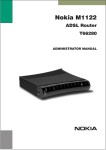
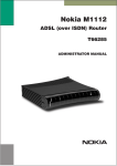
Figure 1-1
Nokia M10
Nokia M10 is a modem with an ADSL router and bridge. This allows a
PC equipped with a 10Base-T Ethernet interface to be connected to a
remote IP network via a Digital Subscriber Line Access Multiplexer
NTC C33539002SE_A0
Copyright Nokia Telecommunications Oy
1-1
DRAFT
Nokia M10 User’s Manual
(DSLAM) and an ATM access network. M10 can also act as a bridge
between the Ethernet LAN and ADSL/ATM network interfaces.
The ADSL transmission is based on a DMT line code and it provides
speeds up to 8 Mbit/s downstream (from the network) and 1 Mbit/s
upstream (to the network). M10 can adjust its speed to the line
conditions in steps of 32 kbit/s maximising the data throughput over
the given distance. M10 is compatible with Nokia Eksos B DSLAM.
M10 provides optimised access to high-speed data services. It can be
used to connect telecommuters to the corporate network or netsurfers
to the Internet Service Provider’s (ISP) network, for example.
As a default, M10 supports plug-and-play operation for an Internet
access application. The ADSL connection, data connection as well as
Internet network addresses are set up automatically.
M10 has an integrated Web server which enables the configuration of
the most frequently used parameters with an ordinary Web browser. It
can also be managed through a command line interface via telnet
protocol or via local console interface.
An external POTS filter enables the simultaneous use of the
conventional telephone service and the ADSL data services.
1-2
Copyright Nokia Telecommunications Oy
NTC C33539002SE_A0
DRAFT
Applications and features
Chapter 2
Applications and features
This chapter introduces the most common applications, features and
management method options of M10.
2.1
Applications
M10 has three main applications:
D
Internet access
D
Remote work
D
LAN interconnection
In these application examples M10 can act as a router, bridge or NAPT
router. The selected mode for every single application depends on the
access and service provider network architectures. Table 2-1 presents
the different application examples and the respective modes of M10.
The application examples described in this manual are marked with
bold ’X’s. See Chapter 6 for more information on routing, bridging and
Network Address Port Translation.
Application
NAPT
Router
Bridge
Business Internet access
X
X
X
Residential Internet access
X
Remote work
X
LAN interconnection
Table 2-1
NTC C33539002SE_A0
X
X
X
X
X
Applications and M10 modes
E Copyright Nokia Telecommunications Oy
2-1
DRAFT
Nokia M10 User’s Manual
2.1.1
Internet access using NAPT router
M10 can connect your PC via your operator’s Digital Subscriber Line
Access Multiplexer (DSLAM) and ATM network to an Internet
service provider (ISP). If you are connected to a single ISP the network
addresses (IP addresses) in your home can be part of the ISP’s IP
address range. However, in many cases it is more practical that the
home network is an independent network utilising private IP addresses
which are not visible to outside and that M10 has only one external IP
address received from the ISP. The external Internet services are
accessed through this single IP address. This mode of operation is
called the Network Port Address Translation (NAPT).
The benefits of NAPT are the minimum coupling of the ISP and the
home network, the saving of public IP addresses, and in–built simple
firewall functionality.
LAN
DSLAM
10Base-T
ATM
network
Home
network
Home
network
ISP Router
Home
network
Nokia M10
Figure 2-1
2-2
Internet
Internet access using NAPT router
Copyright Nokia Telecommunications Oy
NTC C33539002SE_A0
DRAFT
Applications and features
2.1.2
Remote work
In a typical remote work application M10 is used as an IP router to
provide access to corporate Intranet services. Using routing
functionality between the home and the corporate networks prevents
unnecessary broadcast traffic as well as non-IP protocol traffic from
loading the access connection still providing sufficient transparency
for Intranet applications. M10 routing table can be static or can be
updated dynamically using RIP version 1 and RIP version 2 routing
protocols.
DSLAM
10Base-T
ATM
network
Remote
worker
Nokia M10
Remote
worker
Company
router
...
Remote
worker
Figure 2-2
NTC C33539002SE_A0
Corporate
network
Remote work using M10 as a standard router
Copyright Nokia Telecommunications Oy
2-3
DRAFT
Nokia M10 User’s Manual
2.1.3
LAN interconnection using M10 as a bridge
LAN interconnection between a corporate headquarters and its remote
office is another typical application for M10. In the LAN
interconnection application M10 is typically used as an Ethernet
bridge which relays all non-local Ethernet traffic between the
corporate headquarters and remote sites through the ATM core
network.
The benefit of bridging in this application example is the transparency
for all network protocols in a multiprotocol data communications
corporate network.
LAN
DSLAM
10Base-T
ATM
network
Remote
office 1
Nokia M10
...
Company
bridge
Remote
office 2
10Base-T
LAN
Figure 2-3
2.2
Corporate
network
Internet access and LAN interconnection
Functionality
M10 can operate as an OSI layer 3 Internet Protocol (IP) router
between the Ethernet interface and the virtual channels of ADSL/ATM
interface. M10 supports both dynamic and static routing.
2-4
Copyright Nokia Telecommunications Oy
NTC C33539002SE_A0
DRAFT
Applications and features
It can also operate as a self-learning bridge supporting up to 256 MAC
addresses.
Routing
Routing is based on routing entries in a routing table. Static routes are
added via the management interface and dynamic routing is done using
RIP and RIPv2. Routing is done between the Ethernet 10Base-T
interface and the virtual channel connection (VCC) of the ATM/ADSL
interface. Optionally, the routing between the VCCs can be disabled.
M10 supports up to 8 simultaneous VCCs.
Bridging
Bridging is supported if full protocol transparency is required.
Bridging can be used simultaneously with IP routing. M10 works as a
self-learning bridge supporting up to 256 MAC addresses. Bridging is
done between the Ethernet 10Base-T interface and each ATM VCC
interface. Optionally, the bridging between the VCCs can be disabled.
M10 supports up to 8 simultaneous VCCs.
Network Address Port Translation
M10 supports Network Address Port Translation (NAPT) for TCP/IP
and UDP/IP protocols. When NAPT is used a single IP address is
allocated to a VCC to the public IP network. The Ethernet subnet has
private IP addressing and is not visible to the VCC. NAPT translates
the IP source address and source port number dynamically to the VCC
IP address and port number. Similarly packets coming from the VCC
are mapped back to the original destination addresses. NAPT allows
up to 253 hosts to share the single VCC IP address to the public
network. The Network Address Port Translation principle is presented
in Figure 2-4.
src:194.112.11.111:80
dst:192.168.1.112:1228
Figure 2-4
NTC C33539002SE_A0
NAPT router
195.112.12.161
src:192.168.1.112:1228
dst:194.112.11.111:80
Internet (WAN)
192.168.1.254
Home network (LAN)
src:195.112.12.161:1234
dst:194.112.11.111:80
src:194.112.11.111:80
dst:195.112.12.161:1234
Network Address Port Translation
Copyright Nokia Telecommunications Oy
2-5
DRAFT
Nokia M10 User’s Manual
NAPT may restrict the operation of some IP applications. NAPT also
operates as a simple IP firewall because translation is only allowed
when the first packet is transmitted from the LAN because the NAPT
table entry is created on when a packet is sent from the home network
to the Internet. With a pinhole capability the user can add static entries
to the NAPT table allowing the translation always in both directions.
This capability is used to add servers (HTTP, NNTP, and FTP), which
are visible from the public IP network via the VCC, in the LAN subnet
Dynamic Host Configuration
M10 can act as a Dynamic Host Configuration Protocol (DHCP)
server for the PCs in the end-user LAN. In this mode M10 can assign
up to 253 IP addresses to the PCs in the home network.
ATM and ADSL
M10 supports up to 8 simultaneous VCCs and supports UBR
(Unspecified bit rate) traffic shaping on all VCCs. The maximum
transmit rate on each VCC is the ADSL upstream capability. If more
than one VCCs are transmitting simultaneously the ADSL upstream
capability is temporarily shared between these VCCs. When one VCC
is idle the bandwidth is used by another VCC.
The ADSL transmission is based on the DMT line code. M10 provides
a DMT line rate up to 8 Mbit/s downstream and up to 1 Mbit/s
upstream. The DMT transceiver is rate adaptive and capable of
providing faster rates over short distances or slower rates over long
distances. The transceiver adapts itself to the line conditions. The
ADSL interface of M10 functions completely automatically and all
configuration related to the ADSL connection is done at the access
multiplexer in the operator’s premises.
The ATM over ADSL transmission is based on ANSI T1.413 Issue 2
recommendation.
Rate adaptation is done in steps of 32 kbit/s. The network operator can
set the data rates as a part of the network management functionality
provided by Nokia Eksos B DSLAM.
Payload encapsulations
Both routed and bridged protocols are encapsulated in the ATM link by
using either RFC 1483 LLC/SNAP encapsulation or VC multiplexing.
M10 also supports PPP over AAL5 encapsulation, in which both
bridged and routed protocols are first encapsulated in PPP (RFC 1661).
2-6
Copyright Nokia Telecommunications Oy
NTC C33539002SE_A0
DRAFT
Applications and features
PPP is then encapsulated in ATM according to the IETF PPP over
AAL5 using RFC 2364 VC multiplexing.
Routed IP packets can also be encapsulated using LLC/SNAP or
VC-multiplexed Ethernet (bridged) encapsulations. See Chapter 6 for
more information on the payload encapsulations.
2.3
Management
There are four management methods in M10:
D
Command line interface (CLI) over console serial port
D
CLI via telnet
D
SNMP
D
Web browser management
The CLI allows complete configuration of the unit and the Web
browser management addresses the most frequently used
configuration parameters. SNMP can be used to read some equipment
identity information and to provide traps for authentication failures.
NTC C33539002SE_A0
E Copyright Nokia Telecommunications Oy
2-7
DRAFT
Nokia M10 User’s Manual
2-8
Copyright Nokia Telecommunications Oy
NTC C33539002SE_A0
DRAFT
Interfaces and indicator lights
Chapter 3
Interfaces and indicator lights
M10 provides one Ethernet 10Base-T interface and one ADSL line
interface. The ADSL line interface is ANSI T1.413 Issue 2
compatible.
3.1
10Base-T Ethernet interface
The Ethernet interface is a standard 10 Mbit/s half-duplex 10Base-T
interface. The mechanical connector is an 8-pin RJ-45 connector.
ETH
1
Figure 3-1
NTC C33539002SE_A0
8
Ethernet connector location
Copyright Nokia Telecommunications Oy
3-1
DRAFT
Nokia M10 User’s Manual
PIN
Signal
Direction
MDI signal
M10-Ethernet
1
2
3
6
3.2
Tx+
Tx–
Rx+
Rx–
–>
–>
<–
<–
Transmit data +
Transmit data –
Receive data +
Receive data –
ADSL line interface
The ADSL line interface is ANSI T1.413 Issue 2 compatible. The
mechanical connector is a 6-pin RJ-11 connector.
LINE
1
Figure 3-2
3-2
6
ADSL line connector location
PIN
Signal
3
4
DSL1
DSL2
Copyright Nokia Telecommunications Oy
NTC C33539002SE_A0
DRAFT
Interfaces and indicator lights
3.3
Front panel indicator lights
Six indicator lights have been grouped into three groups in the front
panel:
D
D
D
STA
DSL
LAN
STA DSL
LAN
ERR INA COL
OK ACT
LNK
RX
TX
Figure 3-3
Front panel indicator lights
STA indicator
D Err (red): There is a malfunction in the unit. Switch power off and
on again. If this does not help send the unit for repair.
D OK (green): Unit is functional
DSL indicator (ADSL line status)
D INA (red): ADSL line is inactive (no connection). Blinking light
indicates that the ADSL link is training.
D ACT (green): ADSL line is active (connection).
LAN indicators
D COL (red): Blinking light indicates collisions on the Ethernet.
D LNK (green): Lit if the Ethernet connection is OK.
D Rx (green): Blinking light indicates that M10 is receiving Ethernet
packets.
D Tx (green): Blinking light indicates that M10 is transmitting
Ethernet packets.
NTC C33539002SE_A0
E Copyright Nokia Telecommunications Oy
3-3
DRAFT
Nokia M10 User’s Manual
3-4
Copyright Nokia Telecommunications Oy
NTC C33539002SE_A0
DRAFT
Installation
Chapter 4
Installation
This chapter presents a step-by-step installation example procedure
for three different application examples of Nokia M10:
D
D
D
Internet access (NAPT router)
Remote work (basic router)
LAN interconnection (basic bridge)
These installation procedures are examples to guide you through some
of the typical use cases.
The installation examples assume that you have a new M10 with a
factory default configuration. The complete default configuration is
presented in the end of this chapter. The default settings are, briefly:
D
D
D
D
D
D
Single ADSL/ATM channel (VPI = 0, VCI = 100)
PPP over ATM/AAL5 encapsulation
M10 retrieves IP address configuration from the IP network using
PPP-IPCP negotiation
Network Address Port Translation activated
Private IP addresses in use in LAN
DHCP server for the LAN interface activated
Before starting the installation, unpack the unit and check that it is
physically undamaged.
4.1
Internet access (NAPT router)
This application is based on the default configuration of the Nokia
M10. By default, Nokia M10 is an Internet access device that uses
NTC C33539002SE_A0
E Copyright Nokia Telecommunications Oy
4-1
DRAFT
Nokia M10 User’s Manual
Network Address Port Translation between the private home network
and the public Internet.
Customer premises
PC
uses
DHCP
Nokia
M10/NAPT
PPP
ATM
ADSL
Private IP
addresses
low-pass filter
Operator premises
Telephone
cable
PPP
ATM
ADSL
Telephone
network
Filter
ATM
network
DSLAM
single ATM
channel to
the ISP
Internet
ISP router
Figure 4-1
4-2
Internet access application
Copyright Nokia Telecommunications Oy
NTC C33539002SE_A0
DRAFT
Installation
The Internet access application requires that your PC uses Dynamic
Host Configuration Protocol (DHCP) to get its network address (IP
address) from your Nokia M10.
The installation procedure depends on whether you want to use data
services only or data and simultaneous telephone services. If you want
data services only start from the Step 1a. Start from Step 1b if you want
both data and telephone services.
M10 has an optional three-level password (user, user-admin, and
admin) which also affects the installation procedure. By default, the
password is disabled but it can be enabled through the command line
interface (see Chapter 5 Management). Steps 4b and 5b describe the
actions when password is enabled.
Step 1a: Connect cables (data services only)
Connect the following cables:
D
D
D
D
Connect the mains power cord first to the Nokia M10 and to a
power outlet.
Connect the Ethernet cross cable to the Nokia M10 ETH connector
and the other end to your PC’s Ethernet port.
Connect the ADSL cable to the telephone socket.
Go to Step 2.
Step 1b: Connect cables (data and telephone services)
If you want to use your telephone line for both the high-speed ADSL
service and normal telephone service you must install a POTS filter.
You can use Nokia POTS filter T66130 or T66150. See separate
installation instructions for POTS filters.
Connect the following cables:
D
D
D
Connect the mains power cord first to the Nokia M10 and to a
power outlet.
Connect the Ethernet cross cable to the Nokia M10 ETH connector
and the other end to your PC’s Ethernet port.
Connect the ADSL cable and the telephone according to the
separate POTS filter installation instructions.
Step 2: Switch power on
Turn the Nokia M10 on. The green STA indicator and red DSL
indicator light up. After a while the DSL light starts blinking indicating
NTC C33539002SE_A0
E Copyright Nokia Telecommunications Oy
4-3
DRAFT
Nokia M10 User’s Manual
that the connection is being established. Green DSL light indicates that
the unit has a connection to the central office.
Step 3: Turn on your PC
Turn on your PC. The LAN/LNK indicator lights up in the Nokia M10
front panel. Note that you must activate the DHCP functionality in
your PC to make it retrieve an IP address from M10.
Step 4a: Connect to M10 with a Web browser (password disabled)
Start the Web browser in your PC, write the IP address (192.168.1.254)
or the name (”M10”) of the M10 to the HTTP address field and press
Enter. The M10 QuickConfig page is displayed. Note that the
QuickConfig page is displayed first only when M10 has its factory
default settings active. If M10 has been previously configured the first
page to appear is the M10 home page. Go to Step 5a.
Step 4b: Connect to M10 with a Web browser (password enabled)
Start the Web browser in your PC, write the IP address (192.168.1.254)
or the name (”M10”) of the M10 to the HTTP address field and press
Enter. Enter Network Password dialog is shown. Enter your M10 User
name and Password and click OK. Goto Step 5b.
Step 5a: Configure M10 (password disabled)
Click Internet Access-Single PPP button to set your username and
password for the Internet service.
4-4
Copyright Nokia Telecommunications Oy
NTC C33539002SE_A0
DRAFT
Installation
Here it is assumed that the default settings of M10 are suitable for
accessing the Internet through your Internet Service Provider, i.e. the
connection from M10 to the ISP uses PPP over AAL5 protocol, the ISP
provides the required network address information to your M10
automatically, and the default connection channel (VPI and VCI
values) of M10 is correct. This means that you only have to enable the
needed authentication method (CHAP or PAP) by clicking the relevant
radio button and to type in your username and password related to the
authentication method. You will get the information which
authentication method to use and your corresponding username and
password from your Internet Service Provider. After entering the
information click Save and restart M10.
Step 5b: Configure M10 (password enabled)
Enable PAP or CHAP authentication and type in your corresponding
user name and password. You will get the information which
authentication method to use and your corresponding username and
password from your Internet Service Provider. After entering the
information click Save and restart M10.
NTC C33539002SE_A0
Copyright Nokia Telecommunications Oy
4-5
DRAFT
Nokia M10 User’s Manual
Step 6: Surf
After the ADSL connection has been established the installation is
complete and you can use your Web browser normally.
4.2
Remote work (Basic router)
In the remote work application example the Nokia M10 routes you to
your company’s LAN through an ATM network. It is assumed that
your PC belongs to your company’s IP network and has a fixed IP
address. It is also assumed that static IP routing is used. An example is
shown in Figure 4-2.
4-6
Copyright Nokia Telecommunications Oy
NTC C33539002SE_A0
DRAFT
Installation
M10 IP address
192.168.1.1
255.255.255.0
192.168.2.2
255.255.255.0
Nokia M10
RFC 1483
IP/ATM
ATM
ADSL
PC’s IP address:
192.168.1.180
255.255.255.0
DSLAM
ATM
network
Your server
VCI/VPI connected
from DSLAM to
company router
Company LAN
192.168.3.3
Company
router
192.168.2.1
255.255.255.0
Gateway/firewall
192.168.3.4
255.255.255.0
Internet
Figure 4-2
NTC C33539002SE_A0
Remote work application
Copyright Nokia Telecommunications Oy
4-7
DRAFT
Nokia M10 User’s Manual
Here the configuration is done using the command line interface (CLI)
through the console port of Nokia M10. A special cable is needed, type
designation E64320.01.
Step 1: Connect cables
D Connect the mains power cord to your M10 and the other end to the
power outlet.
D Connect the M10 console cable to the console port behind the
hatch in the front panel of your M10. Connect the other end of the
cable to the serial port of your PC/terminal.
! # !
$
Figure 4-3
D
"# Location of the console port
Turn on your Nokia M10. The green status indicator and the red
DSL indicator light up.
Step 2: Turn on your PC and start the terminal software
Set the following terminal software parameters: 9600, 8 bits, no parity,
1 stop bit, no flow control.
Press enter in the terminal window. The Nokia command line interface
prompt will be displayed.
Step 3: Configure the M10
The configurations given here assume that the unit uses its default
configurations and the changes are done on top of the default
configuration.
4-8
E Copyright Nokia Telecommunications Oy
NTC C33539002SE_A0
DRAFT
Installation
The Nokia M10 command line interface includes a step mode to
automate the process of entering configuration settings. When you use
the Config step mode, the CLI prompts you for all required and
optional information. You can enter the configuration values
appropriate for your site without having to enter complete CLI
commands.
When you are in step mode, the CLI prompts you to enter required and
optional settings. If a setting has a default value or a current setting, the
command line interface displays the default value for the command in
parentheses. If a command has a limited number of acceptable values,
those values are presented in brackets, with each value separated by a
vertical line. For example, the following CLI step command indicates
that the default value is off and that valid entries are limited to on and
off.
option (off) [on|off]: on
You can accept the default value for a field by pressing the Enter key.
To use a different value, type it in and press Enter.
Enter the Config step mode by typing set from the top node of the
Config hierarchy. See Chapter 5 section Stepping through M10
configuration for more information on the step mode.
In the following example the values changed by the user are in bold
type. The default values have been accepted by pressing Enter.
M10> config
Config Mode v1.0
(admin level privileges –– read/write
M10 (top)>>set
Stepping set mode (press Control–X <Return/Enter> to
exit)...
system
name (”M10”): <Enter>
Diagnostic Level List
low
medium
high
warnings
failures
diagnostic-level (high): <Enter>
dmt
option (on) [on|off]: <Enter>
NTC C33539002SE_A0
Copyright Nokia Telecommunications Oy
4-9
DRAFT
Nokia M10 User’s Manual
encap (CELL) [HDLC|PPP|CELL]: <Enter>
downRate (1536.0) [1536.0|3072.0|4608.0|
6144.0] CO Only: <Enter>
upRate (64.0) [64.0|160.0|384.0|576.0|640.0]
CO Only: <Enter>
margin (3) [–3 – 9] CO Only: <Enter>
atm
option (on) [on|off]: <Enter>
vcc 1
option (on): <Enter>
vpi (0) [0 – 255]: <Enter>
vci (100) [0 – 65535]: <Enter>
encap (ppp-vcmux)
ppp-vcmux
:
PPP over ATM,
VC-muxed
ether-vcmux :
RFC-1483, briged
Ethernet, VC-muxed
ether-llc
:
RFC-1483, bridged
Ethernet, LLC-SNAP
ip-vcmux
:
RFC-1483, routed IP,
VC-muxed
ip-llc
:
RFC-1483, routed IP,
LLC-SNAP
[ppp-vcmux|ether-vcmux|ether-llc|
ip-vcmux|ip-llc]: ip-llc
vcc 2
option (off): <Enter>
vcc 3
option (off): <Enter>
vcc 4
option (off): <Enter>
vcc 5
option (off): <Enter>
vcc 6
option (off): <Enter>
vcc 7
option (off): <Enter>
vcc 8
option (off): <Enter>
cell
ehead (0x00000001) [0x0 – 0xffffffff]:
<Enter>
epayload (0x6a6a6a6a) [0x0 – 0xffffffff]:
4-10
Copyright Nokia Telecommunications Oy
NTC C33539002SE_A0
DRAFT
Installation
<Enter>
hec_coset (on): <Enter>
payload_scrambling (on): <Enter>
bncp
option (off) [on|off]: <Enter>
ip
option (on) [on|off]: <Enter>
ethernet
option (on) [on|off]: <Enter>
address (192.168.1.254): 192.168.1.1
broadcast (192.168.1.255): <Enter>
netmask (255.255.255.0): <Enter>
proxy-arp (off) [on|off]: <Enter>
rip-send (v1) [off | v1 | v2 |
v1-compat]: <Enter>
rip-receive (v1) [off | v1 | v2 |
v1-compat]: <Enter>
dsl vcc1
option (off) [on|off]: on
address (0.0.0.0): 192.168.2.2
broadcast (0.0.0.255): 192.168.2.255
netmask (255.255.255.0): <Enter>
addr-mapping (on) [on|off]: off
proxy-arp (off) [on|off]: <Enter>
rip-send (v1) [off | v1 | v2 |
v1-compat]: <Enter>
rip-receive (v1) [off | v1 | v2 |
v1-compat]: <Enter>
admin-disable (off) [on|off]: <Enter>
gateway
option (on) [on|off]: <Enter>
interface () [ip-address]: ip-address
default (0.0.0.0): 192.168.2.1
interwan-routing (on) [on|off]: <Enter>
static routes
IP Static Route List
destination-network (0.0.0.0) [enter a
listed or new static route address]: <Enter>
location
Location names: <Enter>
NTC C33539002SE_A0
Copyright Nokia Telecommunications Oy
4-11
DRAFT
Nokia M10 User’s Manual
name (””) [enter a listed or new location name]:
<Enter>
dhcp
option (on) [on|off]: off
dns
domain-name (””): <Enter>
primary-address (0.0.0.0): <Enter>
secondary-address (0.0.0.0): <Enter>
bridge
option (off) [on|off]: <Enter>
interwan-bridging (on) [on|off]: <Enter>
snmp
Community Name List
“public”
community (””): <Enter>
traps
authentication-traps (off) [on|off]:
<Enter>
IP Trap List
ip-traps (0.0.0.0) [enter a listed or
new IP address]: <Enter>
sysgroup
contact (””): <Enter>
location (””): <Enter>
ppp
peer-database
Authentication User List
peer-name (””) [enter a listed or new
user name]: <Enter>
pinhole
Pinhole Table
item (0) [enter a listed or new
pinhole entry]:
servers
4-12
Copyright Nokia Telecommunications Oy
NTC C33539002SE_A0
DRAFT
Installation
web-http (80) [0 – 32767]: <Enter>
telnet-tcp (23) [0 – 32767]: <Enter>
Stepping mode ended.
M10 (top)>> save
WARNING: ’dns domain-name’ is null, indicating no
domain name is available.
WARNING: ’dns primary-address [0.0.0.0]’ and ’dns
secondary-address [0.0.0.0]’ indicates no nameserver
is available.
Configuration data saved.
M10 (top)>> exit
M10> restart
REBOOT scheduled in 2 seconds
Goodbye.
The following changes were made in the above basic router example:
D
D
D
D
D
D
D
Ip-llc encapsulation was selected for the ATM channel 1. This
encapsulation is used by your company’s main office router.
Alternatively vc-mux encapsulation could be used. See Chapter 6
for more information on the payload encapsulations.
IP address was assigned to the Ethernet port of your M10.
IP and broadcast addresses were assigned to the ATM/ADSL
interface of your M10.
Address mapping was disabled because your PC and M10 belong
to your company network.
Default gateway was enabled and its IP address defines the IP
gateway interface.
IP address of the default gateway was given.
DHCP was disabled.
The warnings in the end of the above example indicate that the
addresses have not been specified. 0.0.0.0 setting indicates that M10
retrieves the name server addresses from the network. Warning is not
fatal. If an error message occurs the configuration has not been
validated successfully and M10 does not save the configuration.
NTC C33539002SE_A0
E Copyright Nokia Telecommunications Oy
4-13
DRAFT
Nokia M10 User’s Manual
Step 4: Connect your M10 to the network
Connect the ADSL cable to the telephone socket and the Ethernet
interface to your PC. The green LAN LNK indicator lights up when
you connect the Ethernet cable. After a while the DSL light starts
blinking indicating that the connection is being established. The green
DSL light indicates that the unit has a connection to the central office.
Step 5: Check that the connection works
Ping the company server or the gateway to check that the connection
works.
4.3
LAN interconnection (Basic Ethernet bridge)
In this application example Nokia M10 connects transparently to a
remote office or company headquarters.
Virtual ATM channel
connected from DSLAM
to HQ access bridge
PC
Hub
Nokia
M10/bridge
RFC 1483
Ethernet
over ATM
ADSL ATM
DSLAM
ATM
network
Headquarters
access bridge
Headquarters
LAN
Figure 4-4
4-14
LAN interconnection
Copyright Nokia Telecommunications Oy
NTC C33539002SE_A0
DRAFT
Installation
Step 1: Connect cables
D Connect the mains power cord to your M10 and the other end to the
power outlet.
D Connect the M10 console cable to the console port behind the
hatch in the front panel of your M10. Connect the other end of the
cable to the serial port of your PC/terminal. A special cable is
needed, type designation E64320.01.
D Turn on your Nokia M10. The green status indicator and the red
DSL indicator light up.
! # !
$
Figure 4-5
"# Location of the console port
Step 2: Turn on your PC and start the terminal software
Set the following terminal software parameters: 9600, 8, no parity, no
flow control.
Step 3: Configure the M10 using CLI commands
The configurations given here assume that the unit uses its default
configurations and the changes are done on top of the default
configuration.
The Nokia M10 command line interface includes a step mode to
automate the process of entering configuration settings. When you use
the Config step mode, the CLI prompts you for all required and
optional information. You can enter the configuration values
NTC C33539002SE_A0
E Copyright Nokia Telecommunications Oy
4-15
DRAFT
Nokia M10 User’s Manual
appropriate for your site without having to enter complete CLI
commands.
When you are in step mode, the CLI prompts you to enter required and
optional settings. If a setting has a default value or a current setting, the
command line interface displays the default value for the command in
parentheses. If a command has a limited number of acceptable values,
those values are presented in brackets, with each value separated by a
vertical line. For example, the following CLI step command indicates
that the default value is off and that valid entries are limited to on and
off.
option (off) [on|off]: on
You can accept the default value for a field by pressing the Enter key.
To use a different value, type it in and press Enter.
You can enter the Config step mode by typing set from the top node of
the Config hierarchy.
In the following example the values changed by the user are in bold
type. The default values have been accepted by pressing Enter.
M10> config
Config Mode v1.0
(admin level privileges –– read/write
M10 (top)>>set
Stepping set mode (press Control–X <Return/Enter> to
exit)...
system
name (”M10”): <Enter>
Diagnostic Level List
low
medium
high
warnings
failures
diagnostic-level (high): <Enter>
dmt
option (on) [on|off]: <Enter>
encap (CELL) [HDLC|PPP|CELL]: <Enter>
downRate (1536.0) [1536.0|3072.0|4608.0|
6144.0] CO Only: <Enter>
upRate (64.0) [64.0|160.0|384.0|576.0|640.0]
CO Only: <Enter>
4-16
Copyright Nokia Telecommunications Oy
NTC C33539002SE_A0
DRAFT
Installation
margin (3) [–3 – 9] CO Only: <Enter>
atm
option (on) [on|off]: <Enter>
vcc 1
option (on): <Enter>
vpi (0) [0 – 255]: <Enter>
vci (100) [0 – 65535]: <Enter>
encap (ppp-vcmux)
ppp-vcmux
:
PPP over ATM,
VC-muxed
ether-vcmux :
RFC-1483, briged
Ethernet, VC-muxed
ether-llc
:
RFC-1483, bridged
Ethernet, LLC-SNAP
ip-vcmux
:
RFC-1483, routed IP,
VC-muxed
ip-llc
:
RFC-1483, routed IP,
LLC-SNAP
[ppp-vcmux|ether-vcmux|ether-llc|
ip-vcmux|ip-llc]: ether-llc
vcc 2
option (off): <Enter>
vcc 3
option (off): <Enter>
vcc 4
option (off): <Enter>
vcc 5
option (off): <Enter>
vcc 6
option (off): <Enter>
vcc 7
option (off): <Enter>
vcc 8
option (off): <Enter>
cell
ehead (0x00000001) [0x0 – 0xffffffff]:
<Enter>
epayload (0x6a6a6a6a) [0x0 – 0xffffffff]:
<Enter>
hec_coset (on): <Enter>
payload_scrambling (on): <Enter>
bncp
option (off) [on|off]: <Enter>
NTC C33539002SE_A0
Copyright Nokia Telecommunications Oy
4-17
DRAFT
Nokia M10 User’s Manual
ip
option (on) [on|off]: <Enter>
ethernet
option (on) [on|off]: off
dsl vcc1
option (off) [on|off]: <Enter>
gateway
option (on) [on|off]: off
interwan-routing (on) [on|off]: off<Enter>
static routes
IP Static Route List
destination-network (0.0.0.0) [enter a
listed or new static route address]: <Enter>
location
Location names: <Enter>
name (””) [enter a listed or new location name]:
<Enter>
dhcp
option (on) [on|off]: off
dns
domain-name (””): <Enter>
primary-address (0.0.0.0): <Enter>
secondary-address (0.0.0.0): <Enter>
bridge
option (off) [on|off]: on
ethernet
option (on) [on|off]: <Enter>
dsl vcc1
option (on) [on|off]: <Enter>
interwan-bridging (on) [on|off]: <Enter>
snmp
Community Name List
“public”
community (””): <Enter>
traps
authentication-traps (off) [on|off]:
<Enter>
4-18
Copyright Nokia Telecommunications Oy
NTC C33539002SE_A0
DRAFT
Installation
IP Trap List
ip-traps (0.0.0.0) [enter a listed or
new IP address]: <Enter>
sysgroup
contact (””): <Enter>
location (””): <Enter>
ppp
peer-database
Authentication User List
peer-name (””) [enter a listed or new
user name]: <Enter>
pinhole
Pinhole Table
item (0) [enter a listed or new
pinhole entry]:
servers
web-http (80) [0 – 32767]: <Enter>
telnet-tcp (23) [0 – 32767]: <Enter>
Stepping mode ended.
M10 (top)>> ip
M10 (ip)>> set
Stepping set mode (press Control-X <Return/Enter> to
exit)...
ip
option (on) [on|off]: off
interwan-routing (off) [on|off]: <Enter>
static routes
IP Static Route List
destination-network (0.0.0.0) [enter a
listed or new static route address]:
<Enter>
Stepping mode ended.
NTC C33539002SE_A0
Copyright Nokia Telecommunications Oy
4-19
DRAFT
Nokia M10 User’s Manual
M10 (top)>> save
WARNING: ’dns domain-name’ is null, indicating no
domain name is available.
WARNING: ’dns primary-address [0.0.0.0]’ and ’dns
secondary-address [0.0.0.0]’ indicates no nameserver
is available.
Configuration data saved.
M10 (ip)>> exit
M10> restart
REBOOT scheduled in 2 seconds
Goodbye.
The following changes were made in the above basic router example:
D
D
D
D
Ether-llc encapsulation was selected for the ATM channel 1. This
encapsulation is used by your company’s main office bridge.
Alternatively ether-vcmux encapsulation could be used. See
Chapter 6 for more information on the payload encapsulations.
IP functionality, default gateway and interwan routing were
disabled in the Ethernet. Note, that you have to go through the IP
option twice. First to disable Ethernet and gateway options and
then to disable the IP option.
DHCP option was disabled.
Bridge was enabled.
Warnings related to 0.0.0.0 settings of DNS servers are irrelevant in
this configuration because the M10 is now a transparent bridge.
Warnings are not fatal. If an error message occurs the configuration has
not been validated successfully and M10 does not save the
configuration.
Step 4: Connect your M10 to the network
Connect the ADSL cable to the telephone socket and the Ethernet
interface to your office hub. The green LAN LNK indicator lights up
when you connect the Ethernet cable. After a while the DSL indicator
starts blinking indicating that the connection is being established. The
green DSL light indicates that the unit has a connection to the central
office.
4-20
E Copyright Nokia Telecommunications Oy
NTC C33539002SE_A0
DRAFT
Installation
Step 5: Check that the connection works
Establish a connection to the office server to check that the connection
works.
4.4
Default settings
The table below indicates the default settings for Nokia M10. By
default, Nokia M10 works as a plug and play unit for Internet access
application. Node and Subnode refer to Config command hierarchy
nodes (see Chapter 5).
Node
System
Subnode
Parameter
System name
System Diagnostic Level
System Name
Password/
User
System Name
Password/
Admin
CLI Verbose
CLI Lines
ATM Option
BNCP Option
PPP Option
NTC C33539002SE_A0
M10 default
M10
3 (high)
<empty>
<empty>
OFF
16
ON
0x00000001
Empty Cell
Header Value
Empty Cell
0x6A6A6A6A
Payload Value
ATM HEC
ON
Coset
Payload
ON
Scrambling
ATM VCC OpON (VCC1), others
tions (8)
OFF
VCI (VCC1)
100
VPI (VCCI1)
0
Encapsulation ppp-vcmux
(VCC1)
OFF
ON
Copyright Nokia Telecommunications Oy
4-21
DRAFT
Nokia M10 User’s Manual
Node
Subnode
Parameter
PPP Maximum Receive
Unit
LCP Magic
Number Negotiation
Protocol Compression
Address Compression
LCP Echo Requests
Failures-max
Configuremax
Terminatemax
Restart Timer
Activity Timeout
Chap Option
Chap Name
Chap Secret
PAP Option
PAP Name
PAP Password
Chap Peer
Option
PAP Peer Option
IP Option
4-22
M10 default
1500
ON
OFF
OFF
ON
10
10
2
3
0
OFF
“empty”
“empty”
OFF
“empty”
“empty”
OFF
OFF
Peer Host
“empty”
Name(s)
Peer Host
“empty”
CHAP Secrets
Peer Host
“empty”
PAP Passwords
ON
Copyright Nokia Telecommunications Oy
NTC C33539002SE_A0
DRAFT
Installation
Node
Subnode
Parameter
IP Gateway
Option
IP Ethernet
Option
ON
IP Gateway
ppp (VCC1)
Interface
IP Gateway IP “empty”
Address
ON
IP Ethernet
Address
IP Ethernet
Broadcast Address
IP Ethernet
Netmask
IP Ethernet
RIP send
IP Ethernet
RIP receive
IP WAN Option
IP DSL Option
IP-ppp Option
Static Routes
Tbl
192.168.1.254
192.168.1.255
255.255.255.0
RIP V1
RIP V1
OFF
OFF
ON (VCC1)
IP-PPP IP Ad- 0.0.0.0 (VCC1)
dress
IP-PPP Peer 0.0.0.0 (VCC1)
IP Address
IP-PPP AdON (VCC1)
dress mapping
IP-PPP RIP
OFF
Send
IP-PPP RIP
OFF
Receive
IP-PPP Flush OFF
Routes
Empty
DHCP Option
DHCP Start IP
address
NTC C33539002SE_A0
M10 default
Copyright Nokia Telecommunications Oy
ON
192.168.1.1
4-23
DRAFT
Nokia M10 User’s Manual
Node
Subnode
DNS
Default Domain Name
Primary DNS
Server Address
Secondary
DNS Server
Address
Bridge Option
SNMP
Table 4-1
4.5
Parameter
List of
communities
(table)
SNMP Authentication
Traps
Trap IP Address
Trap Community Name
SysGroup
Contact Info
M10 default
<empty>
0.0.0.0 (The address
will be retrieved from
through the PPP link)
0.0.0.0 (The address
will be retrieved
through the PPP link)
OFF
Public
None
Empty
Public
Empty
Nokia M10 default settings
Troubleshooting
In case the data transmission does not work you can check the
following things:
Is the ADSL connection to the remote network working?
The front panel DSL indicator should be green if the ADSL link is
functioning. You can also view the ADSL link status by giving the
show dsl command line interface command. In case the ADSL link is
not functioning, check that the cables connecting the unit to the
telephone line/splitter are properly attached and then turn on the M10
again. If the ADSL link still does not work contact your service
provider.
4-24
Copyright Nokia Telecommunications Oy
NTC C33539002SE_A0
DRAFT
Installation
Is the Ethernet connection working?
The front panel LAN LNK indicator is green if the Ethernet cable is
properly attached. If not, check that the cables are properly connected.
Check also that you are using a right kind of Ethernet cable. If you
connect your M10 directly to a PC, you should use a cross-connect
cable. If you connect your M10 to a HUB, you should use a direct
cable.
Is the ATM connection working?
You can check if the ATM connection is working by giving the show
atm CLI command. For the ATM connection to be functioning, the
ADSL connection must be working first. In case the ADSL connection
is OK but the ATM connection is not contact your service provider.
Is the PPP connection working?
If you are using PPP to connect to your service provider, you can also
check that your PPP connection is working. You can do this by giving
the show ppp CLI command. If the ADSL link and ATM link are
working but the PPP link is not you should first check that the
username and password you are using on the PPP link are correct. You
can also try to restart the M10 (power-off and power-on) and check if
the connection is established. If these do not work contact your service
provider for help.
NTC C33539002SE_A0
Copyright Nokia Telecommunications Oy
4-25
DRAFT
Management
Chapter 5
Management
M10 can be managed with a Web browser or command line interface
(CLI). The Web configuration pages of M10 can be accessed through
the Ethernet port or through the ADSL/ATM channels of M10. In order
to access the Web management feature, the IP functionality must be
activated and the IP address must be given to the interface.
The command line interface (CLI) can be accessed through the console
port on the M10 front panel. The console interface is an asynchronous
V.24/V.28 character-based interface with 9600 bps, 8 bits, no parity, 1
stop bit and no flow control. A special cable for connecting PC’s serial
port to this interface is available from Nokia, type designation
E64320.01. The CLI contains an in-built step procedure which helps
you to configure you M10 through the CLI. This procedure is
presented in section Stepping through M10 configuration in this
chapter.
The command line interface can also be accessed through the Ethernet
port of M10 or through the ADSL/ATM channels of M10 on top of the
telnet protocol. In order to use the CLI through telnet, IP functionality
must be activated and IP address must be given to the interface.
5.1
Browser management
You can use your PC’s Web browser software to access the Web
configuration pages in M10. To access the Web pages you must know
the IP address of your M10 or, alternatively, the “name” that your M10
recognises.
NTC C33539002SE_A0
Copyright Nokia Telecommunications Oy
5-1
DRAFT
Nokia M10 User’s Manual
5.1.1
Opening a connection
To open a connection to the Nokia M10 follow the next steps:
1. Start your Web browser.
2. Enter the name or IP address of your Nokia M10 in the browser’s
Open Location field and press enter.
For example, you would enter http://192.168.1.254 if your Nokia
M10 is using its default IP address. The default name is M10.
Note
If a password has been assigned to your Nokia M10,
enter your username and password and click OK. Now
PAP and CHAP Setup page appears, see Figure 5-4.
3. The Nokia M10 home page appears. If you connect to your M10
for the first time the QuickConfig page appears.
Figure 5-1
M10 home page
4. Use the links on the Nokia M10 home page to issue a command or
open a window.
D
D
5-2
QuickConfig link opens the QuickConfig window which lets you
enter basic Internet access application settings for your Nokia
M10.
Monitor link opens the Monitor window which displays operating
statistics for your Nokia M10.
E Copyright Nokia Telecommunications Oy
NTC C33539002SE_A0
DRAFT
Management
D
D
D
D
D
D
5.1.2
Router link is used to configure some generic routing/IP address
management parameters and Ethernet interface IP parameters if
M10 is used as a router.
Bridge link is used to enable bridging and attach interfaces to the
bridge function.
ATM link is used to activate ATM channels, select payload
encapsulations to ATM and configure important ATM channel
parameters.
DSL link opens the DSL Port Configuration window which lets
you configure the DSL port settings of M10 when the unit is
working in frame (not ATM) mode on the ADSL line.
Restart M10 link restarts your M10 causing it to activate any
updated configuration information.
SNMP link is used to configure the SNMP parameters of M10.
QuickConfig page
The QuickConfig page lets you enter basic configuration information
for your Nokia M10. To display the QuickConfig page, click
QuickConfig on the M10 homepage.
Figure 5-2
QuickConfig page
By clicking the Internet Access-Single PPP button you can enter basic
Nokia M10 settings for an Internet access application. Normally you
only need to enter your username and password for the Internet
service.
If you have configured multiple PPP channels into use, you can
manage them through the PPP Connection Manager.
If a password has been assigned to you M10 the PAP and CHAP Setup
page will be displayed instead of the QuickConfig page.
NTC C33539002SE_A0
E Copyright Nokia Telecommunications Oy
5-3
DRAFT
Nokia M10 User’s Manual
QuickStart settings
Figure 5-3
QuickStart page
1. Change virtual path and channel identifiers if needed.
VPI and VCI are used to select the connection channel that is used
between M10 and the Internet service provider (ISP). Normally
you do not have to change these values.
2. Enable PAP or CHAP if needed. Enter the respective username
and password.
3. Enter local LAN Domain Name if required.
4. Enter Domain Name Server addresses if required. Normally these
are assigned automatically and the user should not fill these fields.
5. Save the configuration and restart M10.
You must save the new configuration and restart your M10 for
your changes to take effect.
5-4
Copyright Nokia Telecommunications Oy
NTC C33539002SE_A0
DRAFT
Management
PAP and CHAP Setup settings
If a password has been assigned to your M10 PAP and CHAP Setup
page will appear when you enter your M10 username and password
and click OK.
On this page you can enable/disable PAP/CHAP and enter the
corresponding usernames and passwords. By clicking the Pinhole link
you can go to the NAT Pinhole page and configure pinhole settings.
Monitor link takes you to the Monitor page where you can monitor the
performance of your M10.
Figure 5-4
PAP and CHAP Setup page
PPP Connection Manager settings
You can set the username and password for each PPP connection you
have configured. Select the PPP connection you want to modify from
the option menu. Press Get values to modify username and password
of the connection. Press Reload to restart the PPP connection of the
selected channel. The PPP connection will be restarted and new CHAP
or PAP values will be used.
NTC C33539002SE_A0
Copyright Nokia Telecommunications Oy
5-5
DRAFT
Nokia M10 User’s Manual
Figure 5-5
5-6
PPP Connection manager pages
Copyright Nokia Telecommunications Oy
NTC C33539002SE_A0
DRAFT
Management
5.1.3
Router page
Router page is used to configure ’global’ parameters of the IP routing
functionality of M10, as well as IP parameters of the Ethernet
interface.
Figure 5-6
NTC C33539002SE_A0
Router page
Copyright Nokia Telecommunications Oy
5-7
DRAFT
Nokia M10 User’s Manual
Entering router settings
1. Enter the name of your M10 in the System Name field.
Each M10 is assigned a name as a part of its factory initialisation.
The default name is M10. A device name can be 1-16 characters
long and cannot include spaces or special characters. The name
can be later used to access the M10 through a telnet connection or a
Web page from the Ethernet interface.
2. Enter the IP address of your M10.
Local address is the IP address of your M10’s Ethernet interface.
3. Enter the subnet mask.
Subnet mask is used to identify the network portion of an IP
address. The subnet mask specifies which bits of the 32-bit binary
IP address represent network information. Most sites should use
255.255.255.0 for their subnet mask.
4. Enter the broadcast address.
Broadcast address is used to send messages to all computers on
your network. Most sites should use xxx.yyy.zzz.255 as their
broadcast address, where xxx.yyy.zzz is the network portion of the
IP address.
5. Enter RIP settings for the Ethernet interface.
Rip-send and Rip-receive radio buttons are used to enable
dynamic routing using Routing Information Protocol (RIP). RIP
and RIP version 2 can be used. RIP-send with V1-compat option
enables the sending of RIPv2 packets using multicast. RIP-receive
with V1-compat option accepts both RIPv1 and RIPv2 packets.
6. Enable/disable routing between ATM VCCs (Routing Policy).
IP forwarding and dynamic route distribution between ATM VCC
routing can be disabled when multiple VCCs are used.
7. Enable/disable default gateway.
The default gateway is the host to which your M10 will send a
packet when it does not know how to reach the packet’s
destination host.
5-8
Copyright Nokia Telecommunications Oy
NTC C33539002SE_A0
DRAFT
Management
8. Select the default gateway port from the Interface option menu.
The default gateway port can be one of the active PPP channels or a
specified IP address defined in Default Address field (see step 9.).
9. Enter IP address for your default gateway if you selected
’ip-address’ in step 8.
10. Enter domain name server settings.
A domain name server is a network computer responsible for
matching host names to numeric IP addresses so that network
traffic can be routed correctly. These fields are set if DNS
addresses are not allocated dynamically. Consult your service
provider for further assistance.
Domain names identify organisations on the Internet. The domain
name is usually the domain name of your company or your ISP.
If secondary name server address is configured the M10 relays the
name service request to that server if the primary name server is
unavailable.
11. Enable/disable DHCP server.
As a Dynamic Host Control Protocol (DHCP) server your M10
can assign IP addresses to other devices on your LAN. If you want
your M10 to assign IP addresses, enter the first number of the IP
address range in the Start Address field and the last number of the
IP address range to the End Address field. Lease Time indicates
how often the PC will renew the DHCP lease.
If you want your M10 to relay the DHCP request to an external
server you can do this by enabling relay-agent and entering the
server’s IP address to the Server Address field.
Note
NTC C33539002SE_A0
If you use M10 as a DHCP server, you should assign IP
addresses outside the M10’s DHCP address range to
devices requiring static IP addresses. Before M10
assigns an IP address to a DHCP client, it verifies that
no other device is using that address. However,
network conflicts can result when the M10 assigns an
address in its DHCP range to one device and the
another device configured to use that address is turned
on.
Copyright Nokia Telecommunications Oy
5-9
DRAFT
Nokia M10 User’s Manual
12. Change M10 Web-HTTP port number if needed.
You can change M10 internal Web server port number default
value 80 if the same number is used for pinhole functionality.
13. Change M10 telnet port number if needed.
You can change M10 internal telnet server port number default
value 23 if the same number is used for pinhole functionality.
14. Click Go to NAT Setup to configure the pinhole functionality, if
needed.
15. Enter static routes
Static route identifies a manually configured route to a remote
network. Unlike dynamic routes, which are acquired and
confirmed periodically from other routers, static routes do not time
out.
You can enter static routes by entering the remote router’s
destination address, net mask and gateway address. After you
have entered the required information click Add.
16. Save the configuration.
You must save the new configuration. Save command takes you to
the M10 home page.
17. Restart your M10.
You must restart your M10 by clicking Restart M10 for your
changes to take effect.
5-10
Copyright Nokia Telecommunications Oy
NTC C33539002SE_A0
DRAFT
Management
5.1.4
Bridge page
Bridge page is used to enable/disable bridging. When bridging is
enabled the page is used to select the interfaces which are included in
the bridging function.
Figure 5-7
Bridge page
Only those ATM interfaces which support ’ether-llc’ or ’ether-vcmux’
encapsulation or ’ppp-vcmux’ encapsulation with BNCP support can
be used in bridging operation.
Entering bridge settings
1. Turn on bridge
2. Click ATM to configure ATM channels, if needed (see Section
5.1.5).
3. Select the interfaces you want to use for bridging.
Ethernet indicates the Ethernet interface of M10. DSL VCC [N]
radio buttons indicate ATM channels using ’ether-llc’ or
’ether-vcmux’ encapsulation. WAN VCC [N] radio buttons
indicate ATM channels using ’ppp-vcmux’ encapsulation with
BNCP support.
4. Enable/disable bridging between ATM VCCs.
This option can be used when multiple M10s are connected
together using bridged connection. Disabling the bridging
between the VCCs eliminates the loops from the bridged network.
NTC C33539002SE_A0
Copyright Nokia Telecommunications Oy
5-11
DRAFT
Nokia M10 User’s Manual
5. Save the configuration.
You must save the new configuration. Save command takes you to
the M10 home page.
6. Restart your M10.
You must restart your M10 by clicking Restart M10 for your
changes to take effect.
5.1.5
ATM page
ATM page is used to enable/disable ATM channels and select the
payload encapsulation method for the particular channel. After
enabling an ATM channel you can configure the channel in more detail
through the ATM-channel-specific Config buttons.
Figure 5-8
ATM page
Entering ATM settings
1. Enable a channel by selecting the encapsulation from the option
menu. Up to eight ATM channels can be used.
5-12
Copyright Nokia Telecommunications Oy
NTC C33539002SE_A0
DRAFT
Management
2. Configure the ATM channels.
Click Config button for the channel you want to configure.
Configuring ATM channels
PPP over ATM (VC-muxed)
Figure 5-9
ATM channel configuration page (VC–muxed)
1. Set the virtual path and virtual channel identifications.
NTC C33539002SE_A0
Copyright Nokia Telecommunications Oy
5-13
DRAFT
Nokia M10 User’s Manual
2. Enable/disable IP.
IP Settings allows you to activate the IP layer function of the ATM
channel. Local address and peer address specify the basic IP
address parameters of the ATM channel interface (PPP over
ATM). If you enter 0.0.0.0 to these fields the M10 will try to get
them from the network either using IPCP protocol (ATM channel
using PPP) or DHCP (ATM channel not using PPP).
Address mapping radio button activates/deactivates the Network
Address Port Translation (NAPT).
3. Configure Routing Information Protocol (RIP) settings.
Enable/disable dynamic routing for the active IP interface on the
ATM channel by selecting the corresponding radio buttons. If
RIP-send is selected the M10 sends RIP messages (version 1, 2 or
both) to the network. If RIP-receive is selected the M10 listens to
RIP messages from the network. RIP-send with V1-compat option
enables the sending of RIPv2 packets using multicast. RIP-receive
with V1-compat option accepts both RIPv1 and RIPv2 packets. If
you enable Flush Routes the learned routes are deleted when the
PPP connection is disconnected.
4. Add static routes to the routing table of the interface.
Enter destination address, net mask and gateway and click Add.
5. Save the configuration.
You must save the new configuration. Save command takes you to
the M10 home page.
6. Restart your M10.
You must restart your M10 by clicking Restart M10 for your
changes to take effect.
5-14
Copyright Nokia Telecommunications Oy
NTC C33539002SE_A0
DRAFT
Management
Other encapsulations
Figure 5-10
ATM channel configuration page (other encaps.)
1. Set the virtual path and virtual channel identifications.
2. Enable/disable IP.
IP settings allows you to activate the IP layer function of the ATM
channel. Local address, netmask and broadcast address specify
the basic IP address parameters of the ATM channel interface (IP
over RFC1483). If you enter 0.0.0.0 to these fields the M10 will try
to get them from the network either using IPCP protocol (ATM
channel using PPP) or DHCP (ATM channel not using PPP).
Address mapping radio button activates/deactivates the Network
Address Port Translation (NAPT).
NTC C33539002SE_A0
Copyright Nokia Telecommunications Oy
5-15
DRAFT
Nokia M10 User’s Manual
3. Configure Routing Information Protocol (RIP) settings.
Enable/disable dynamic routing for the active IP interface on the
ATM channel by selecting the corresponding radio buttons. If
RIP-send is selected the M10 sends RIP messages (version 1, 2 or
both) to the network. If RIP-receive is selected the M10 listens to
RIP messages from the network. RIP-send with V1-compat option
enables the sending of RIPv2 packets using multicast. RIP-receive
with V1-compat option accepts both RIPv1 and RIPv2 packets.
4. Add static routes to the routing table of the interface.
Enter destination address, net mask and gateway and press Add.
5. Save the configuration.
You must save the new configuration. Save command takes you to
the M10 home page.
6. Restart your M10.
You must restart your M10 by clicking Restart M10 for your
changes to take effect.
5-16
Copyright Nokia Telecommunications Oy
NTC C33539002SE_A0
DRAFT
Management
5.1.6
NAT pinhole page
NAT pinhole page is used to make servers located in LAN visible to
WAN through a VCC. It allows fixed NAPT mapping between
WAN/VCC IP address/port number and internal LAN IP address/port
number. Separate entries are created for TCP and UDP ports.
The standard port numbers for the most common protocols are:
D
D
D
D
HTTP (Hypertext Transfer Protocol) is TCP port 80
FTP (File Transfer Protocol) is TCP port 21
SMTP (Simple Mail Transfer Protocol) is TCP port 25
NNTP (Network News Transfer Protocol) is TCP port 119
Figure 5-11
NAT pinhole page
1. Enter the External Port Start and External Port End number. These
define the available range of allowed external ports (port number
in WAN interface). Select the protocol. Enter Internal IP address
(server IP address in LAN) and Internal Port number (server port
number in LAN).
2. Click Add.
3. Repeat until each server’s information is filled.
4. To remove entry just press delete.
Pinhole configuration example
The pinhole configuration example in Figure 5-12 can be used to allow
access from WAN to a Web server in LAN. The example configuration
relays the traffic coming to the M10 WAN TCP port 80 to the LAN IP
address 192.168.1.1 port 80. Port 80 is a standard TCP port for HTTP.
NTC C33539002SE_A0
E Copyright Nokia Telecommunications Oy
5-17
DRAFT
Nokia M10 User’s Manual
5-18
Note
M10’s integral Web server used for monitoring and
configuration uses also port 80 by default. You must
change the Server Port Setup through the Router page
or else the TCP traffic to this port is directed to the M10
Web server instead of the Web server in LAN.
Figure 5-12
Pinhole configuration example
Copyright Nokia Telecommunications Oy
NTC C33539002SE_A0
DRAFT
Management
5.1.7
SNMP page
SNMP page is used to configure the SNMP-related parameters of
M10. In M10, the SNMP can be used only for writing/reading system
contact information and trap addresses. Trap address is an address to
which a trap is sent in case of an authentication violation.
Figure 5-13
SNMP page
Entering SNMP settings
1. Enter contact information and system location information in the
corresponding fields.
2. Enable/disable authentication traps.
3. Add/delete user communities, if needed.
Enter the name of the new user community into the field.
4. Enter trap destination addresses.
Enter the IP addresses of the hosts to which the traps are sent. Enter
also the community string related to this address.
NTC C33539002SE_A0
Copyright Nokia Telecommunications Oy
5-19
DRAFT
Nokia M10 User’s Manual
5. Save the configuration.
You must save the new configuration. Save command takes you to
the M10 home page.
6. Restart your M10.
You must restart your M10 by clicking Restart M10 for your
changes to take effect.
5.1.8
Monitor page
You can get information about the status and statistics of the M10
through the Monitor page. The following links are available on the
Monitor page.
D
D
D
D
D
D
D
D
D
D
D
D
D
D
D
Overview displays the basic identification information of M10.
Memory displays the memory usage of M10.
Show displays the Diagnostic log of M10.
Reset scrolls the Diagnostic log window back to the first message.
PPP displays status information about the IP/PPP interfaces.
Ethernet displays status information of the Ethernet interface.
ATM displays status information of the ATM channels.
Interfaces displays status information of the active interfaces.
Routes displays the routing table.
ARP displays the ARP cache table.
DHCP Server displays the DHCP server lease table.
DHCP Client displays the IP address settings M10 has received
from the network.
DSL displays the the status of the ADSL connection and statistics
about the connection.
Table displays the bridge table
Home returns to home page.
Figure 5-14
5-20
Monitor page
E Copyright Nokia Telecommunications Oy
NTC C33539002SE_A0
DRAFT
Management
5.2
Command line interface
The Nokia M10 operating software includes a command line interface
(CLI) that lets you monitor and configure your M10 over a telnet or a
local serial console connection. You can use the CLI to enter and
update a Nokia M10’s configuration settings, monitor its performance,
and restart it. Some CLI commands are not available until certain
conditions are met. For example, you must turn a function on before
you can enter settings for that function.
The commands of the CLI are divided into two hierarchies: Root and
Config. The Root command hierarchy lets you monitor the
performance of your M10, display and reset M10 statistics, and issue
administrative commands to restart M10 functions. The Config
command hierarchy lets you configure the settings of your M10.
5.2.1
Starting and ending a CLI session
You can open a command line interface session by opening a telnet
connection from a workstation on your network to an M10 Ethernet or
ADSL port or by connecting a terminal to the console port on the Nokia
M10.
Connecting from telnet
You initiate a telnet connection by issuing the following command
from an IP host that supports telnet (or a personal computer running a
telnet application such as Microsoft or NCSA Telnet).
telnet ADSL_ip_address
You must know the IP address of the Nokia M10 before you can
connect to is via a telnet connection to it. You can use a Web browser or
the serial console to configure the M10’s IP address.
Connecting from the console port
You can connect a terminal or a terminal emulator to the console port
on the Nokia M10 front panel to configure, administer, and monitor
your Nokia M10. To use the Nokia M10 console, you need a serial
cable and either a terminal or a terminal emulator (such as a personal
computer with a terminal emulation application that supports
9600-baud communication).
To connect your Nokia M10 to a terminal or terminal emulators:
NTC C33539002SE_A0
Copyright Nokia Telecommunications Oy
5-21
DRAFT
Nokia M10 User’s Manual
1. Plug the serial cable E64320.01 into the console port behind the
hatch on the Nokia M10 front panel.
2. Connect the other end of the serial cable to the serial port on your
terminal (or terminal emulator) or the serial port of your computer.
3. Turn on the terminal or run the terminal emulator program on your
computer.
Use the following settings to configure your terminal emulation
session:
Setting
Value
Speed
9600
Parity
None
Data bits
8
Stop bits
1
Duplex
Full
Flow control
None
The console interface uses the same command line interface as the
telnet interface.
Logging in
The command line interface login process emulates the login process
for a Unix host. If your Nokia M10 has been assigned an administrator
password, you must enter a username (up to 32 characters) and your
administrator or user password.
Entering your username lets the Nokia M10 record your access; your
username is not used to validate your authorisation. Entering the
administrator password lets you display and update Nokia M10
settings. Entering a user password lets you display (but not update)
Nokia M10 settings.
When you have logged in successfully, the command line interface
lists the username and the security level (admin or user) associated
with the password you entered in the diagnostic log.
Entering commands in Nokia M10 CLI
CLI commands consist of keywords and arguments. Keywords in a
Config command specify the action you want to take or the entity on
5-22
Copyright Nokia Telecommunications Oy
NTC C33539002SE_A0
DRAFT
Management
which you want to act. Arguments in a Config command specify the
values appropriate to your site. For example, the Config command set
ip ip-ppp address ip_address consists of three keywords (ip,
ip-ppp, and address) and one argument (ip_address). When you
configure your M10, you replace command arguments with values
appropriate to your site. For example, set ip ip-ppp address
192.31.222.57
The optional arguments are marked with braces {argument} and the
mandatory arguments with square brackets [argument].
The Table 5-1 provides guidelines for formatting CLI commands.
Command component
Rules for entering CLI commands
Command word
CLI commands must start with a command
word (set, show, delete). You can truncate
CLI commands to three characters (set,
sho, del). CLI commands are not casesensitive. You can enter “SET“, “Set“ or set.
Keywords
Keywords are not case-sensitive. You can
enter “system, “System“ or “SYSTEM“ as a
keyword without changing its meaning. Keywords can be abbreviated to the length that
they are differentiated from other keywords.
For example, you can reduce the command
“set ip ip-ppp option on“ to “set i i
o on“.
Argument text
Text strings can be as many as 32 characters
long, unless otherwise specified. Special
characters are represented using backslash
notation. Text strings may be enclosed in
double (”) or single (’) quote marks. If the text
string includes an embedded space, it must
be enclosed in quotes.
Numbers
Enter numbers as integers.
IP addresses
Enter IP addresses in dotted decimal notation
(nnn.nnn.nnn.nnn, where nnn = 0 to 255).
Table 5-1
CLI syntax
If a command is ambiguous or miskeyed, the Nokia CLI prompts you
to enter additional information.
NTC C33539002SE_A0
Copyright Nokia Telecommunications Oy
5-23
DRAFT
Nokia M10 User’s Manual
Ending a CLI session
You end a command line interface session by typing quit in the Root
mode. Entering quit in the Config mode switches the session into the
Root mode.
Using the CLI help facility
The help command lets you display on-line help for Root and Config
commands. To display a list of the commands available to you from
your current location in the command line interface hierarchy, type
help. To display help related to a particular command type the
command followed by a question mark, e.g. show ?.
Saving settings
The save command saves the working copy of the settings to restart
values. You can save the changes you have entered for a specific
function or for all functions in the Nokia M10. The Nokia M10
automatically validates its settings when you save and displays a
warning message if the configuration is not correct.
5.2.2
The Root command hierarchy
You begin in Root mode when you start a CLI session. The Root mode
lets you monitor the performance of your M10, display and reset M10
statistics, and issue administrative commands to restart M10
functions.
Root prompt
When you are in Root mode, the CLI prompt is the name of the M10
followed by a right angle bracket (>). For example, if you open a
command line interface to the M10 named “Kilo” you would see
Kilo> as your CLI prompt.
Root command shortcuts
You can truncate most commands in the command line interface to
their shortest unique string. For example, you can use the truncated
command q in place of the full quit command to exit the command
line interface. However, you would need to enter rese for the reset
command, since the first characters of reset are common to the
restart command.
5-24
Copyright Nokia Telecommunications Oy
NTC C33539002SE_A0
DRAFT
Management
The only command you cannot truncate is restart. To prevent
accidental interruption of communications, you must enter the
restart command in its entirety.
You can use the !! command to repeat the last command you entered.
You can press the Ctrl-P or Esc-k key sequences to obtain the same
result.
Root commands
You can get a list of the Root commands by typing ? in the Root
prompt.
D
D
D
D
D
D
D
D
D
D
D
D
D
D
help command
configure command
ping command
atmping command
arp command
quit command
reset command
restart command
show command
telnet command
who command
log command
loglevel command
install command
D
D
D
download command
upload command
clear command
to get help
to configure unit’s options
to send ICMP Echo request
to send ATM OAM loopback
to send ARP request
to quit shell
to reset subsystems
to restart unit
to show system information
to telnet to a remote host
to show who is using the shell
to add a message to the diagnostic log
to report or change diagnostic log level
to download and program an image
into flash
to download a config file
to upload a config file
to erase all stored configuration
information
The following tables present the Root commands, their detailed
descriptions, syntax and usage examples.
NTC C33539002SE_A0
E Copyright Nokia Telecommunications Oy
5-25
DRAFT
Nokia M10 User’s Manual
5-26
Command
Send ARP request
Description
Sends an Address resolution protocol request to match
the nnn.nnn.nnn.nnn IP address to an Ethernet hardware address.
Syntax
arp [nnn.nnn.nnn.nnn]
Arguments
The argument is an IP string which consists of four
decimal numbers with values between 0 and 255 separated by dots.
Example
M10> arp 192.221.11.11
Command
Clear configuration settings
Description
Clears the configuration settings of your M10. Issuing
the restart command after the clear command restores the default configuration. clear command alone
clears the configuration and brings M10 into an undefined state.
Syntax
clear {yes}
Arguments
If you do not use the optional yes argument CLI
prompts you to confirm the clear command.
Example
M10> clear yes
Copyright Nokia Telecommunications Oy
NTC C33539002SE_A0
DRAFT
Management
Command
Download software update
Description
Downloads a new version of the Nokia M10 operating
software from a TFTP (Trivial File Transfer Protocol)
server, validates the software image, and programs the
image into the Nokia M10 memory. After you install new
operating software, you must restart the Nokia M10.
Syntax
install [server_address] [filename] {confirm}
Arguments
The TFTP server must be accessible on your Ethernet
network or through one of the active ATM virtual channels and a route to the server must exist. The server
address argument identifies the IP address of the
TFTP server on which your Nokia M10 operating software is stored. The filename argument identifies the
path and name of the operating software file on the
TFTP server. If you include the optional confirm keyword, you will not be prompted to identify a TFTP
server or file name. Your Nokia M10 begins the software installation using its default boot settings.
Example
M10> install 192.168.1.1 m10c_500.d39
*** WARNING *** YOU ARE ABOUT TO ERASE
AND REPROGRAM THE NOKIA M10’S PERMANENT
SOFTWARE STORAGE WITH A NEW SOFTWARE VERSION OBTAINED VIA THE TFTP PROTOCOL.
About to install new Flash EPROM software
image:
server: 192.168.1.1
file: “m10c_500.d39”
Do you wish to proceed? (type ’yes’ to
confirm): yes
Installing
M10>
Command
Add message to log
Description
Adds the message in the message_string argument
to the Nokia M10 diagnostic log.
Syntax
log [message_string]
Arguments
message_string argument is the message you want
to add to the log.
Example
M10> log 05/05/99
NTC C33539002SE_A0
Copyright Nokia Telecommunications Oy
5-27
DRAFT
Nokia M10 User’s Manual
5-28
Command
Define log level
Description
Displays or modifies the types of log messages you
want the Nokia M10 to record. You can enter the loglevel command with the level argument to specify the
types of diagnostic messages you want to record. All
messages with a level number equal to or greater than
the level you specify are recorded.
Syntax
loglevel {level}
Arguments
If you enter the loglevel command without the optional level argument, the Nokia CLI displays the current log level setting. The values for the argument are:
1 or low
Trivial status messages.
2 or medium Messages that can help
monitor the network traffic.
3 or high
Status messages that may be
significant but do not
constitute errors.
4 or warning Recoverable error conditions
and useful operator
information
5 or failure Messages describing error
conditions that may not be
recoverable
Example
M10> loglevel 3
Command
Ping
Description
Causes the Nokia M10 to issue a series of ICMP Echo
requests for the device with the specified IP address.
You can use the ping command to determine whether
an IP address is already in use on your network. You
cannot use the ping command to ping the Nokia M10’s
own IP address. If a host using the specified IP address
is active, it returns one or more ICMP Echo replies,
confirming that it is accessible from your network.
Syntax
ping [ip_address]
Arguments
ip_address argument is the IP address, in dotted
decimal notation, of the device you want to locate.
Example
M10> ping 192.122.12.11
Copyright Nokia Telecommunications Oy
NTC C33539002SE_A0
DRAFT
Management
Command
ATM ping
Description
Sends 5 OAM F5 loopback cells to the specified VPI/
VCI destination with a 5 second total timeout interval.
Syntax
atmping [vpi] [vci] [segment | end-to-end]
Arguments
vpi and vci specify the channel and the third argument specifies segment or end-to-end loopback.
Example
m10> atmping 0 100 segment
Command
Exit
Description
Exits the Nokia M10 command line interface.
Syntax
quit
Arguments
None.
Example
M10> quit
Command
Reset ATM statistics
Description
Resets ATM statistics to zero.
Syntax
reset atm
Arguments
None
Example
M10> reset atm
Command
Clear crash information
Description
Clears crash-dump information which identifies the contents of M10 registers at the point of system malfunction.
Syntax
reset crash
Arguments
None.
Example
M10> reset crash
NTC C33539002SE_A0
Copyright Nokia Telecommunications Oy
5-29
DRAFT
Nokia M10 User’s Manual
5-30
Command
Reset DHCP server leases
Description
Resets DHCP server leases.
Syntax
reset dhcp server
Arguments
None
Example
M10> reset dhcp server
Command
Release DHCP client lease
Description
Resets DHCP client lease of the WAN port.
Syntax
reset dhcp client lease
Arguments
None
Example
M10> reset dhcp client lease
Command
Retrieve DHCP client configuration
Description
Retrieves the DHCP client configuration for the WAN
port.
Syntax
reset dhcp client retrieve
Arguments
None
Example
M10> reset dhcp client retrieve
Command
Reset ADSL connection
Description
Resets the ADSL connection.
Syntax
reset dsl
Arguments
None.
Example
M10> reset dsl
Command
Reset Ethernet statistics
Description
Resets the Ethernet statistics to zero.
Syntax
reset enet
Arguments
None.
Example
M10> reset enet
Copyright Nokia Telecommunications Oy
NTC C33539002SE_A0
DRAFT
Management
Command
Rewind log
Description
Rewinds the diagnostic log display to the top of the existing M10 diagnostic log. The reset log command
does not clear the diagnostic log. The next show log
command will display information from the beginning of
the log file.
Syntax
reset log
Arguments
None.
Example
M10> reset log
Command
Reset PPP connection
Description
Resets and restarts the PPP connection of the specified ATM logical channel. When you issue the reset
ppp command the Nokia M10 closes the PPP session
on the specified ATM channel and restarts the connection.
Syntax
reset ppp [vccx]
Arguments
vccx indicates the ATM channel, x = 1 – 8.
Example
M10> reset ppp vcc1
Command
Reset packet statistics
Description
Resets packet statistics to zero.
Syntax
reset xdsl
Arguments
None
Example
M10> reset xdsl
Command
Restart M10
Description
Restarts M10. You must enter the the complete restart
command to initiate a restart.
Syntax
restart {seconds}
Arguments
If you include the optional seconds arguments your
Nokia M10 will restart when the specified number of
seconds has elapsed.
Example
M10> restart 5
NTC C33539002SE_A0
Copyright Nokia Telecommunications Oy
5-31
DRAFT
Nokia M10 User’s Manual
5-32
Command
Show crash information
Description
Displays the most recent crash information.
Syntax
show crash
Arguments
None.
Example
M10> show crash
Command
Show DHCP server leases in RAM
Description
Displays the DHCP leases stored in RAM.
Syntax
show dhcp server leases
Arguments
None.
Example
M10> show dhcp server leases
Command
Show DHCP server leases in NVRAM
Description
Displays the DHCP leases stored in NVRAM
Syntax
show dhcp server store
Arguments
None.
Example
M10> show dhcp server store
Command
Show DHCP client parameters
Description
Displays the DHCP client parameters of the WAN port.
Syntax
show dhcp client
Arguments
None.
Example
M10> show dhcp client
Copyright Nokia Telecommunications Oy
NTC C33539002SE_A0
DRAFT
Management
Command
Show Ethernet statistics
Description
Displays the Ethernet statistics of your M10.
Syntax
show enet {all}
Arguments
Optional argument all displays more detailed information.
Example
M10> show enet
Ethernet driver statistics, device 0:
Packets out:
16578
Packets in:
11
Xmit errors:
0
Recv errors:
0
CRC errors:
0
Frame errors: 0
No buffers:
0
No handler:
0
No message:
0
M10>
NTC C33539002SE_A0
Copyright Nokia Telecommunications Oy
5-33
DRAFT
Nokia M10 User’s Manual
Command
Show ADSL information
Description
Displays the current status and some statistics about
the ADSL connection, e.g. upstream and downstream
data rates.
Syntax
show dsl
Arguments
None.
Example
M10> show dsl
DSL Statistics:
Type: ADI DMT
Datapump HW Rev: 0
Datapump FW Rev: 2220ca05
Current Status: Operational
Init Status: Initialization successful
Last Init Status: Initialization successful
Downstream
Upstream
Current rate
7968000 bps
640000 bps
Maximum rate
10336000 bps
832000 bps
Fast parity bytes
0
0
Fast Codeword Size 1
1
Int Parity Bytes
10
8
Int Codeword Size
136
184
Interleve Depth
8
0
Near
Error seconds
Noise Margin
Attenuation
Transmitted blocks
Received Blocks
Corrected Blocks
Uncorrected Blocks
M10>
5-34
end
0
7 db
17 db
34814571
34814433
0
0
Copyright Nokia Telecommunications Oy
NTC C33539002SE_A0
DRAFT
Management
Command
Show ATM information
Description
Displays the current status and some statistics of the
active ATM channels.
Syntax
show atm {all}
Arguments
Optional argument all displays more detailed information.
Example
M10> show atm
ATM port status: Cell delineation
achieved
Serial Rx relay: 4
Rx data rate (bps): 7968000
Tx data rate (bps): 640000
VCC# Type VPI VCI Bound Encapsulation
–––––––––––––––––––––––––––––––––––––
1
PVC
0 100 Yes PPP over ATM (VCmuxed)
M10>
Command
Show ARP table
Description
Displays the Ethernet address resolution table stored in
M10.
Syntax
show ip arp
Arguments
None.
Example
M10> show ip arp
NTC C33539002SE_A0
Copyright Nokia Telecommunications Oy
5-35
DRAFT
Nokia M10 User’s Manual
Command
Show IP interfaces
Description
Displays the IP interfaces of your M10.
Syntax
show ip interfaces
Arguments
None.
Example
M10> show ip interfaces
IP Interfaces:
ENET (lan): (up broadcast default ripsend v1 rip-receive v1)
inet 192.168.1.254
netmask ffffff00
broadcast 192.168.1.255
physical address 00.40.43.08.ff.ff
mtu 1500
PPP (vcc1): (up point-to-point rip-send
v2 rip-receive v2)
inet 10.98.20.21
netmask 0
peer address 10.98.20.1
physical address
00.00.00.00.00.00
mtu 1500
M10>
Command
Show IP routes
Description
Displays the IP routes stored in your M10.
Syntax
show ip routes
Arguments
None.
Example
M10> show ip routes
IP gateway (route) table:
0. Default Gateway –> PPP (vcc1), D 2, T
0, (configured) UP DEFAULT
IP route cache
Net 192.168.1.1, gateway 192.168.1.1,
metric 0, timeout 0, via ENET (lan)
Net 192.168.1.255, broadcast, via ENET
(lan)
M10>
5-36
Copyright Nokia Telecommunications Oy
NTC C33539002SE_A0
DRAFT
Management
Command
Show diagnostic log
Description
Displays blocks of information from the Nokia M10
diagnostic log.
Syntax
show log {all}
Arguments
to see the entire log you can repeat the show log command or you can use the argument all and scroll
through the complete log.
Example
M10> show log all
Command
Show memory usage
Description
Displays the memory usage of your M10.
Syntax
show memory {all}
Arguments
Optional argument all displays more detailed information.
Example
M10> show memory all
Command
Show PPP information
Description
Displays information about open PPP links.
Syntax
show ppp {stats | lcp | ipcp | bncp | lastconnect}
Arguments
You can display a subset of the PPP statistics by including optional stats, lcp, ipcp, bncp, or lastconnect argument.
Example
M10> show ppp
NTC C33539002SE_A0
Copyright Nokia Telecommunications Oy
5-37
DRAFT
Nokia M10 User’s Manual
Command
Show M10 information
Description
Displays current status of a Nokia M10, the device’s
hardware and software revision levels, a summary of
errors encountered, and the length of time the Nokia
M10 has been running since it was last restarted.
Syntax
show status
Arguments
None.
Example
M10> show status
Terminal shell v1.0
M10 multiport ADSL router/bridge
Running Nokia M10 software version 5.0.0
(build D35)
Software built by alan on Fri Nov 13
14:02:16 EST 1998
(completed login: admin level)
Serial number J984001344, CPU MPC860,
firmware 2.2
Product ID T66160.09 0
Error logger message counts:
Low 0, Medium 0, High 61, Warning 26,
Lost 0, Total 87
Boot state: running in dram
Uptime 00:00:12:25
M10>
5-38
Command
Open telnet session
Description
Opens a telnet session to a remote host
Syntax
telnet [host] {port}
Arguments
host is the IP address of the remote host. Optional
argument indicates the port of the remote host.
Example
M10> telnet 1.12.123.123
Command
Show users
Description
Displays the names and hostnames of the current shell
users.
Syntax
who
Arguments
None
Example
M10> who
Copyright Nokia Telecommunications Oy
NTC C33539002SE_A0
DRAFT
Management
Command
Download configuration file
Description
Downloads a configuration file from a TFTP server.
Syntax
download [server-ipaddress] [filename] {confirm}
Arguments
server-ipaddress is the IP address of the TFTP
server. filename is the name of the configuration file.
If invoked as download with no arguments, you will be
prompted for information. If the optional confirm keyword is added, the transfer will proceed without further
questions.
Example
M10> download 1.12.123.123 config1.cfg
***WARNING*** YOU ARE ABOUT TO DOWNLOAD A
CONFIGURATION FILE.
About to download configuration file:
server: 1.12.123.123
file: config1.cfg
Do you wish to proceed? (type ’yes’ to
confirm):yes
Downloading
Downloading file into RAM
File Download was successful
Replace existing configuration with downloaded configuration? (type ’yes’ to confirm):yes
172.16.0.0 has been added to the
list
Configuration data saved.
M10>
Command
Upload configuration file
Description
Uploads a configration file to a TFTP server.
Syntax
upload [server-ipaddress] [filename] {confirm}
Arguments
server-ipaddress is the IP address of the TFTP
server. filename is the name of the configuration file.
If invoked as upload with no arguments, you will be
prompted for information. If the optional confirm keyword is added, the transfer will proceed without further
questions.
Example
M10> upload 1.12.123.123 config2.cfg confirm
NTC C33539002SE_A0
Copyright Nokia Telecommunications Oy
5-39
DRAFT
Nokia M10 User’s Manual
5.2.3
Config command hierarchy
The Config mode lets you configure the parameters of your M10. The
command hierarchy consists of nodes and subnodes. Each node
contains the configurable parameters of that particular function.
system
vcc:1
dmt
vcc:2
vcc
vcc:3
cell
vcc:4
atm
vcc:5
bncp
vcc:6
vcc:7
ethernet
ip
vcc:8
dsl
vcc:N
wan
vcc:N
gateway
location
ip–ppp
top
dhcp
dns
bridge
vcc:N
static_routes
ethernet
vcc:N
dsl
vcc:N
wan
vcc:N
snmp
ip trap list
sysgroup
module
peer authentication
ppp
vcc:N
pinhole
vcc:N
servers
peer_database
5-40
port authentication
Copyright Nokia Telecommunications Oy
vcc:N
NTC C33539002SE_A0
DRAFT
Management
Config prompt
You reach the configuration mode of the M10 CLI by typing config at
the Root prompt. When you are in Config mode, the CLI prompt
consists of the name of your M10 followed by your current node in the
hierarchy and two angle brackets (>>). For example, when you enter
Config mode (by typing config at the Root prompt), the M10
(top)>> prompt reminds you that you are at the top of the Config
hierarchy. If you move to the ip node in the Config hierarchy (by
typing ip at the Config prompt), the prompt changes to M10 (ip)>> to
identify your current location.
Navigating the Config hierarchy
You start at the top when you enter Config mode. The command line
interface reminds you of your location by showing your current node
after the M10 name:
M10 (top)>>
D
Moving from Config to Root
You can navigate from anywhere in the Config hierarchy back to
the Root level by entering the quit command at the Config
command prompt and pressing Enter.
M10 (top)>> quit
M10>
D
Moving from top to a subnode
You can navigate from the top node to a subnode by entering the
node name (or the significant letters of the node name) at the
Config prompt and pressing Enter. For example, you move to the
ip subnode by entering ip and pressing Enter.
M10 (top)>> ip
M10 (ip)>>
As a shortcut, you can enter the significant letters of the node in
place of the full node name at the Config prompt. The significant
characters of a node name are the letters that uniquely identify the
node. For example, only the atm Config node starts with a, you
could enter one letter (”a”) to move to the atm node.
M10 (top)>> a
M10 (atm)>>
NTC C33539002SE_A0
E Copyright Nokia Telecommunications Oy
5-41
DRAFT
Nokia M10 User’s Manual
You would have to enter two or more letters (”ppp”) to move to the
PPP node, since its node name shares the first letter with the
preferences node.
D
Jumping down several nodes at once
You can jump down several levels in the Config hierarchy by
entering the complete path to a node.
M10 (top)>> ip ip-ppp
M10 (ip ip-ppp)>>
D
Moving up one node
You can move through the Config hierarchy one node at a time by
entering the up command.
M10 (ip ip-ppp)>> up
M10 (ip)>>
D
Jumping to the top node
You can jump to the top level from anywhere in the Config
hierarchy by entering the top command.
M10 (ip ip-ppp)>> top
M10 (top)>>
D
Moving from one subnode to another
You can move from one subnode to another by entering a partial
path that identifies how far back to climb.
M10 (ip ip-ppp)>> ppp module
M10 (ppp module)>>
D
Moving from any subnode to any other subnode
You can move from any subnode to any other subnode by entering
a partial path that starts with a top-level Config command.
M10 (ip ip-ppp)>> ip gateway
M10 (ip gateway)>>
5-42
E Copyright Nokia Telecommunications Oy
NTC C33539002SE_A0
DRAFT
Management
D
Entering commands without changing nodes
You can enter a complete Config command from anywhere in the
hierarchy without changing your current node.
M10 (ip ip-ppp)>> set system diag high
M10 (ip ip-ppp)>>
Here diagnostic level is set high in the system without jumping to
the node first.
Displaying current settings
You can use the show command to display the current Root settings of
your M10. When you are in Config mode, you use the show command
to display the current Config settings. If you enter the show command
at the top level of the Config hierarchy, the command line interface
displays the settings for all enabled functions in the M10. If you enter
the show command at an intermediate node, you see all settings for that
node and its subnodes.
Stepping through M10 configuration
The Nokia M10 command line interface includes a step mode to
automate the process of entering configuration settings. When you use
the Config step mode, the CLI prompts you for all required and
optional information. You can enter the configuration values
appropriate for your site without having to enter complete CLI
commands.
When you are in step mode, the CLI prompts you to enter required and
optional settings. If a setting has a default value or a current setting, the
command line interface displays the default value for the command in
parentheses. If a command has a limited number of acceptable values,
those values are presented in brackets, with each value separated by a
vertical line. For example, the following CLI step command indicates
that the default value is off and that valid entries are limited to on and
off.
option (off) [on|off]: on
You can accept the default value for a field by pressing the Enter key.
To use a different value, type it in and press Enter.
You can enter the Config step mode by typing set from the top node of
the Config hierarchy. You can enter step mode for a particular node by
typing set node_name. For example:
NTC C33539002SE_A0
E Copyright Nokia Telecommunications Oy
5-43
DRAFT
Nokia M10 User’s Manual
M10 (top)>> set system
Stepping set mode (press Control-X <Enter> to exit)
system
name (”M10”): Kutoja
Diagnostic Level (High): medium
Stepping mode ended
See Chapter 4 for step mode installation examples.
Validating your configuration
You can use the validate command to make sure that your
configuration settings have been entered correctly. If you use the
validate command M10 verifies that all required settings are present
and that the settings are consistent.
M10 (top)>> validate
Error: Subnet mask is incorrect
Global Validation did not pass inspection!
You can use the validate command to verify your configuration
settings at any time. Your M10 automatically validates your
configuration any time you save a modified configuration.
Config command reference
The top level configuration command nodes are listed below:
D
D
D
D
D
D
D
D
D
D
D
D
D
D
system
preference
atm
bncp
ip
location
dhcp
dns
bridge
dmt
snmp
ppp
pinhole
servers
Unit system options
CLI preferences
ATM options
BNCP options
TCP/IP options
Location Manager options
DHCP options
DNS options
Bridge options
DMT ADSL options
SNMP options
PPP options
NAT/NAPT server configuration
Local integrated server configuration
The sections below explain the commands under each top level
configuration node.
5-44
E Copyright Nokia Telecommunications Oy
NTC C33539002SE_A0
DRAFT
Management
System settings
You can configure system settings to assign a name to your Nokia M10
and to specify what types of messages you want the diagnostic log to
record.
Command
Set system name
Description
Specifies the name of your Nokia M10. Each Nokia
M10 is assigned a name as a part of its factory initialisation. The default name for Nokia M10 is “M10”.
Once you have assigned a name to your Nokia M10,
you can enter that name in the Open Location text field
of your browser to open a connection to your Nokia
M10.
Syntax
set system name [name]
Arguments
name is an alphanumeric string of 16 characters.
Example
m10> set system name M10
Command
Set diagnostic level
Description
Specifies the types of log messages you want the M10
to record. All messages with a level number equal to or
greater than the level you specify are recorded.
Syntax
set system diagnostic-level {level}
Arguments
If you enter the command without the optional level
argument, the Nokia CLI displays the current diagnostic
level setting. The values for the level argument are:
1 or low
Trivial status messages.
2 or medium Messages that can help
monitor the network traffic.
3 or high
Status messages that may be
significant but do not
constitute errors.
4 or warning Recoverable error conditions
and useful operator
information.
5 or failure Messages describing error
conditions that may not be
recoverable.
Example
m10> set system diagnostic-level 3
NTC C33539002SE_A0
Copyright Nokia Telecommunications Oy
5-45
DRAFT
Nokia M10 User’s Manual
Command
Set password
Description
Specifies the administrator, user-administrator, or user
password for a Nokia M10. When you enter the set
system password command, you are prompted to
repeat the new password to verify that you entered it
correctly the first time. To prevent anyone from observing the password you enter, characters in the old and
new passwords are not displayed as you type them. A
password can be as many as eight alphanumeric characters. Passwords are case-sensitive and cannot include special characters or leading, trailing, or embedded spaces. For example, if you assign a password
of “NokiA” to an M10, you could not enter “NOKIA”,
“nokia”, “Nokia”, or “Nokia “ (with a trailing space) as an
acceptable password.
Syntax
set system password [admin | user-admin | user]
Arguments
Arguments admin, user-admin and user specify
whether administrator, user-administrator or user password will be set. User password gives only viewing
rights. User-admin password gives rights to change
PAP and CHAP usernames and passwords and configure pinhole settings. You must set an admin password
before you can set user or user-admin passwords.
Example
m10> set system password admin *****
Note
5-46
An administrator or user password goes into effect
immediately. You do not have to restart the M10 for the
password to take effect. Assigning an administrator or
user password to M10 does not affect communications
through the device.
Copyright Nokia Telecommunications Oy
NTC C33539002SE_A0
DRAFT
Management
CLI preferences
You can set the CLI preferences to customize your environment.
Command
Set CLI help mode
Description
Specifies whether you want command help and
prompting information displayed. By default, the CLI
verbose preference is turned off. If you turn it on, the
CLI displays help for a node when you navigate to that
node.
Syntax
set preference verbose [on | off]
Arguments
The argument enables/disables verbose mode.
Example
m10> set preference verbose off
Command
Set display length
Description
Specifies how many lines of information you want the
CLI to display at one time.
Syntax
set preference more [lines]
Arguments
The lines argument specifies the number of lines you
want to see at one time. By default, the command line
interface shows you 16 lines of text before displaying
the prompt More ... [y|n]?. If you enter 0 as the
lines argument the CLI displays information as an
uninterrupted stream (which is useful for capturing information to a text file).
Example
m10> set preference more 20
NTC C33539002SE_A0
Copyright Nokia Telecommunications Oy
5-47
DRAFT
Nokia M10 User’s Manual
ATM settings
You can enable ATM over ADSL operation and configure up to eight
ATM channels into use. You can select between five different ways to
encapsulate your payload in an ATM channel. You can also fine tune
the physical layer parameters of the ATM channel. See also DMT
(ADSL) settings on page 5-78.
5-48
Command
Enable/disable ATM
Description
Enables/disables the use of ATM on the ADSL link. Disabling ATM forces M10 to work in a frame mode on the
ADSL link.
Syntax
set atm option [on | off]
Arguments
The argument enables/disables ATM.
Example
m10> set atm option on
Command
Set ATM cell header of an empty cell
Description
Defines the ATM cell header of an empty (idle) ATM cell
as an 8-bit variable. This command affects the low-level
functionality of the ATM physical layer link and usually
you do not have to change this setting.
Syntax
set atm cell ehead [0xbbbbbbbb]
Arguments
ADSL standard value is 0x00000001 or 0x00000000
depending on the DSLAM. Nokia B20 requires the
value 0x00000001.
Example
m10> set atm cell ehead 0x00000001
Command
Set payload content of an empty cell
Description
Defines the payload content of an empty (idle) ATM cell
as an 8-bit variable. This command affects the low-level
functionality of the ATM physical layer link and usually
you do not have to change this setting.
Syntax
set atm cell epayload [0xbbbbbbbb]
Arguments
ADSL standard value is 0x6A6A6A6A.
Example
m10> set atm cell epayload 0x6A6A6A6A
Copyright Nokia Telecommunications Oy
NTC C33539002SE_A0
DRAFT
Management
Command
Enable/disable header error correction coset function
Description
Enables/disables ATM header error correction coset
function in the ATM link. This command affects the lowlevel functionality of the ATM physical layer link and
usually you do not have to change this setting.
Syntax
set atm cell hec_coset [on | off]
Arguments
ADSL standard value is ON.
Example
m10> set atm cell hec_coset off
Command
Enable/disable ATM payload scrambling
Description
Enables/disables the scrambling of the ATM payload on
the ADSL/ATM link. This command affects the low-level
functionality of the ATM physical layer link and usually
you do not have to change this setting.
Syntax
set atm cell payload_scrambling [on | off]
Arguments
ADSL standard value is ON.
Example
m10> set atm cell payload_scrambling off
Command
Enable/disable specific ATM channel
Description
Enables/disables the specific logical ATM virtual channels. M10 supports up to eight ATM virtual channels.
Syntax
set atm vcc [1 | 2 | 3 | 4 | 5 | 6 | 7 | 8] option [on | off]
Arguments
The first argument 1|2|3|4|5|6|7|8 specifies the
channel and the second argument enables/disables it.
Example
m10> set atm vcc 1 option off
NTC C33539002SE_A0
Copyright Nokia Telecommunications Oy
5-49
DRAFT
Nokia M10 User’s Manual
5-50
Command
Set virtual path identifier for ATM channel
Description
Sets the virtual path identifier for the specific logical
ATM channel. M10 is delivered to you with a default virtual circuit identifier so usually you do not have to
change this setting.
Syntax
set atm vcc [1 | 2 | 3 | 4 | 5 | 6 | 7 | 8] vpi [0–255]
Arguments
The first argument 1|2|3|4|5|6|7|8 specifies the
channel and the second argument sets the virtual path
identifier.
Example
m10> set atm vcc 2 vpi 30
Command
Set virtual channel identifier for ATM channel
Description
Sets the virtual channel identifier for the specified logical ATM channel. M10 is delivered to you with a default
circuit identifier and usually you do not have to change
this setting.
Syntax
set atm vcc [1 | 2 | 3 | 4 | 5 | 6 | 7 | 8] vci [0–65535]
Arguments
The first argument 1|2|3|4|5|6|7|8 specifies the
channel and the second argument sets the virtual channel identifier.
Example
m10> set atm vcc 2 vci 1221
Copyright Nokia Telecommunications Oy
NTC C33539002SE_A0
DRAFT
Management
Command
Set payload encapsulation for specific ATM channel
Description
Defines how the payload is capsulated to the specified
logical ATM channel.
Syntax
set atm vcc [1 | 2 | 3 | 4 | 5 | 6 | 7 | 8] encap [ip-llc | ipvcmux | ether-llc | ether-vcmux | ppp-vcmux]
Arguments
The first argument 1|2|3|4|5|6|7|8 specifies the
channel and the second argument sets the encapsulation. The ip-llc and ether-llc encapsulations are according to RFC 1483 with LLC/SNAP encapsulation for ip
and Ethernet frames, respectively. The ip-vcmux and
ether-vcmux encapsulation are vc-multiplexed according to RFC 1483 for IP and Ethernet frames, respectively. In ppp-vcmux encapsulation both bridged and
routed protocols are first encapsulated to point-to-point
protocol (PPP) which is, in turn, encapsulated to ATM
according to RFC 1483 vc-multiplexing.
Example
m10> set atm vcc 2 encap ip-llc
NTC C33539002SE_A0
Copyright Nokia Telecommunications Oy
5-51
DRAFT
Nokia M10 User’s Manual
TCP/IP settings
You can use the Nokia command line interface to specify whether
TCP/IP is enabled, identify a default gateway, and to enter TCP/IP
settings for the Nokia M10 Ethernet port and all active ATM/ADSL
channels.
Depending on the ATM channel encapsulation the IP settings are
configured in different nodes (dsl, wan or ip-ppp) of the Config
hierarchy as shown in Figure 5-15.
ip-llc
ip-vcmux
ether-llc
ether-vcmux
PPP with
BNCP on
ip
PPP
Figure 5-16
5-52
dsl
wan
ip–ppp
IP setting nodes
Copyright Nokia Telecommunications Oy
NTC C33539002SE_A0
DRAFT
Management
Command
Enable/disable TCP/IP services
Description
Enables/disables TCP/IP services in the Nokia M10.
You must enable TCP/IP services before you can enter
other TCP/IP settings for the M10. If you turn off TCP/
IP services and save the new configuration, the M10
clears its TCP/IP settings.
Syntax
set ip option [on|off]
Arguments
The argument enables/disables TCP/IP
Example
m10> set ip option on
Command
Enable/disable Ethernet port
Description
Enables/disables communications through the Ethernet
port in the Nokia M10. You must enable TCP/IP functions for an Ethernet port before you can configure its
network settings.
Syntax
set ip ethernet option [on|off]
Arguments
The argument enables/disables Ethernet port.
Example
m10> set ip ethernet option on
Command
Set Ethernet port IP address
Description
Assigns an IP address to the Ethernet port. The IP address you assign to an Ethernet port must be unique on
your network.
Syntax
set ip ethernet address [ip_address]
Arguments
The ip_address argument is the IP address, in dotted
decimal notation
Example
m10> set ip ethernet address
191.212.11.11
NTC C33539002SE_A0
Copyright Nokia Telecommunications Oy
5-53
DRAFT
Nokia M10 User’s Manual
5-54
Command
Set broadcast address
Description
Specifies the broadcast address for the TCP/IP network
connected to the Ethernet port. IP hosts use the broadcast address to send messages to every host on your
network simultaneously.
Syntax
set ip ethernet broadcast [broadcast_address]
Arguments
The broadcast address for most networks is the network number followed by 255. For example, the broadcast address for the 192.31.222.0 network would be
192.31.222.255.
Example
m10> set ip ethernet broadcast
192.31.222.255
Command
Set netmask
Description
Specifies the subnet mask for the TCP/IP network connected to the Ethernet port. The subnet mask specifies
which bits of the 32-bit binary IP address represent network information.
Syntax
set ip ethernet netmask [netmask]
Arguments
The default subnet mask for most networks is
255.255.255.0 (Class C subnet mask).
Example
set ip ethernet netmask 255.255.255.0
Command
Enable/disable RIP send function
Description
Specifies whether the M10 should use Routing information protocol (RIP) broadcasts to advertise its routing
tables to other routers on your network. RIP cannot be
activated if address mapping is ON.
Syntax
set ip ethernet rip_send [off | v1 | v2 | v1-compat]
Arguments
Both RIP version 1 and RIP version 2 functionalities
can be simultaneously activated. v1-compat argument
enables the sending of RIPv2 packets using IP multicast.
Example
m10> set ip ethernet rip_send off
Copyright Nokia Telecommunications Oy
NTC C33539002SE_A0
DRAFT
Management
Command
Enable/disable RIP receive function
Description
Specifies whether the M10 should use Routing information protocol (RIP) broadcasts to update its routing
tables with information received from other routers on
your network. RIP cannot be activated if address mapping is ON.
Syntax
set ip ethernet rip_receive [off | v1 | v2 | v1-compat]
Arguments
Both RIP version 1 and RIP version 2 functionalities
can be simultaneously activated. v1-compat argument
enables the receiving of both RIPv1 and RIPv2 packets.
Example
m10> set ip ethernet rip_receive off
Command
Enable/disable default gateway
Description
Specifies whether the M10 should send packets to a
default gateway if it does not know how to reach the
destination host.
Syntax
set ip gateway option [on|off]
Arguments
The argument enables/disables the default gateway option.
Example
m10> set ip gateway option on
Command
Select gateway interface
Description
Specifies how M10 should route information to the default gateway.
Syntax
set ip gateway interface [ip_address | ppp_vccx]
Arguments
If you select ip_address, you must enter the IP address of a host acting as a default gateway on a local
or remote network. If you specify a PPP on ATM channel, the M10 uses the default gateway being used by
the remote PPP peer behind that ATM channel. Acceptable values for ’x’ are the ATM channels using ppp–
vcmux encapsulation.
Example
m10> set ip gateway interface ip-address
NTC C33539002SE_A0
Copyright Nokia Telecommunications Oy
5-55
DRAFT
Nokia M10 User’s Manual
Command
Set default gateway IP address
Description
Specifies the IP address of the default IP gateway. Only
applies when the default gateway interface is ip-address.
Syntax
set ip gateway default [ip_address]
Arguments
ip_address argument is the IP address of the default
gateway.
Example
m10> set ip gateway default 191.233.22.1
Command
Enable IP packet forwarding and route distribution
between ATM VCC interfaces
Description
Enable/disable IP packet forwarding and route distribution between ATM VCC interfaces. If only one VCC is
used this option can be ignored.
Syntax
set ip interwan-routing [on|off]
Arguments
The argument enables/disables interwan routing.
Example
m10> set ip interwan-routing on
Use the following commands to configure settings for routing IP over
PPP link.
Command
Enable/disable routing IP over PPP link
Description
Enables/disables IP routing through the specified logical ATM channel using ppp-vcmux encapsulation.
Syntax
set ip ip-ppp {vccx} option [on|off]
Arguments
The first argument identifies the ATM channel (vccx, x =
1 ... 8). If there is only one ATM channel using pppvcmux encapsulation you can leave the argument vccx
out. The on/off argument enables/disables routing.
Example
m10> set ip ip-ppp vcc1 option off
Note
5-56
You must enable IP routing before you can enter other
IP routing settings for the serial port. If you turn off IP
routing and save the new configuration, the Nokia
M10 clears IP routing settings.
Copyright Nokia Telecommunications Oy
NTC C33539002SE_A0
DRAFT
Management
Command
Set IP address to ATM channel using PPP-vcmux
encapsulation
Description
Assigns an IP address to the specified logical ATM
channel using ppp-vcmux encapsulation.
Syntax
set ip ip-ppp {vccx} address [ip_address]
Arguments
The first argument identifies the ATM channel (vccx, x =
1 ... 8). If there is only one ATM channel using pppvcmux encapsulation you can leave the argument vccx
out. If you specify an IP address other than 0.0.0.0,
your Nokia M10 will not negotiate its IP address with
the remote peer. If the remote peer does not accept the
IP address specified in the ip_address argument as
valid, the link will not come up. The default value for the
ip_address argument is 0.0.0.0, which indicates that
the WAN port will use the IP address assigned to it by
the remote peer. Note that the remote peer must be
configured to supply an IP address to your Nokia M10 if
you enter 0.0.0.0 for the ip_address argument.
Example
m10> set ip ip-ppp vcc2 address 0.0.0.0
Command
Set peer IP address
Description
Specifies the IP address of the peer on the other end of
the logical ATM link using ppp-vcmux encapsulation.
Syntax
set ip ip-ppp {vccx} peer-address [ip_address]
Arguments
The first argument identifies the ATM channel (vccx, x =
1 ... 8). If there is only one ATM channel using pppvcmux encapsulation you can leave the argument vccx
out. If you specify an IP address other than 0.0.0.0,
your Nokia M10 will not negotiate the remote peer’s IP
address. If the remote peer does not accept the address in the ip_address argument as its IP address
(typically because it has been configured with another
IP address), the link will not come up. The default value
for the ip_address argument is 0.0.0.0, which indicates that the WAN port will accept the IP address returned by the remote peer. If you enter 0.0.0.0, the peer
system must be configured to supply this address.
Example
m10> set ip ip-ppp vcc2 peer-address
0.0.0.0
NTC C33539002SE_A0
Copyright Nokia Telecommunications Oy
5-57
DRAFT
Nokia M10 User’s Manual
5-58
Command
Enable/disable address mapping on ATM link using
PPP-vcmux encapsulation
Description
Specifies whether you want Nokia M10 to use NAPT on
the specified ATM link using ppp-vcmux encapsulation
when communicating with remote routers. Address
mapping lets you conceal details of your network from
remote routers, which is useful when connecting to an
Internet Service Provider. By default, the address mapping is turned on.
Syntax
set ip ip-ppp {vccx} addr-mapping [on|off]
Arguments
The first argument identifies the ATM channel (vccx, x =
1 ... 8). The second argument enables/disables address mapping on that channel.
Example
m10> set ip ip-ppp vcc2 addr-mapping on
Command
Enable/disable RIP send function on PPP link
Description
Specifies whether the Nokia M10 should use Routing
information protocol (RIP) broadcasts to advertise its
routing tables to router on the other side of the specified ATM link using ppp-vcmux encapsulation. RIP cannot be activated if address mapping is ON.
Syntax
set ip ip-ppp {vccx} rip-send [off | v1 | v2 | v1-compat]
Arguments
The first argument identifies the ATM channel (vccx, x =
1 ... 8). If there is only one ATM channel using pppvcmux encapsulation you can leave the argument vccx
out. Both RIP version 1 and RIP version 2 functionalities can be simultaneously activated. v1-compat
argument enables the sending of RIPv2 packets using
IP multicast.
Example
m10> set ip ip-ppp vcc2 rip-send off
Copyright Nokia Telecommunications Oy
NTC C33539002SE_A0
DRAFT
Management
Command
Enable/disable RIP receive function on PPP link
Description
Specifies whether the Nokia M10 should use Routing
information protocol (RIP) broadcasts to update its routing tables with information received from other routers
on the other side of the specified ATM link using pppvcmux encapsulation. RIP cannot be activated if address mapping is ON.
Syntax
set ip ip-ppp {vccx} rip-receive [off | v1 | v2 | v1-compat]
Arguments
The first argument identifies the ATM channel (vccx, x =
1 ... 8). If there is only one ATM channel using pppvcmux encapsulation you can leave the argument vccx
out. Both RIP version 1 and RIP version 2 functionalities can be simultaneously activated. v1-compat
argument enables the receiving of both RIPv1 and
RIPv2 packets.
Example
m10> set ip ip-ppp vccx rip-receive off
Command
Enable/disable the management through PPP link
Description
Enables/disables the management of Nokia M10
through the specified ATM link using ppp-vcmux encapsulation.
Syntax
set ip ip-ppp {vccx} admin-disable [on|off]
Arguments
The first argument identifies the ATM channel (vccx, x =
1 ... 8). If there is only one ATM channel using pppvcmux encapsulation you can leave the argument vccx
out. The second argument disables/enables management through the PPP link.
Example
m10> set ip ip-ppp vcc2 admin-disable on
NTC C33539002SE_A0
Copyright Nokia Telecommunications Oy
5-59
DRAFT
Nokia M10 User’s Manual
5-60
Command
Enable/disable IP routing on channels using IP
over ATM or bridged encapsulations
Description
Enables/disables IP routing on the specified ATM channel using the IP over ATM encapsulations (ip-llc, ipvcmux) or bridged encapsulations (ether-llc, ethervcmux).
Syntax
set ip dsl {vccx} option [on|off]
Arguments
The first argument identifies the ATM channel and the
second argument enables/disables IP routing. If there
is only one ATM channel using one of these encapsulations you can leave the argument vccx out.
Example
set ip dsl vcc2 option off
Command
Set IP address to channels using IP over ATM or
bridged encapsulations
Description
Assigns an IP address to the specified logical ATM
channel using ip-llc, ip-vcmux, ether-llc, or ether-vcmux
encapsulation.
Syntax
set ip dsl {vccx} address [ip_address]
Arguments
The first argument identifies the ATM channel (vccx, x =
1 ... 8). The second argument is the IP address of that
channel. If there is only one ATM channel using one of
these encapsulations you can leave the argument
vccx out. If you enter 0.0.0.0 as the IP address Nokia
M10 will retrieve the IP address through the remote
peer using Dynamic Host Configuration Protocol.
Example
m10> set ip dsl vcc2 address 0.0.0.0
Copyright Nokia Telecommunications Oy
NTC C33539002SE_A0
DRAFT
Management
Command
Set broadcast address to channels using IP over
ATM or bridged encapsulations
Description
Assigns a broadcast IP address to the specified logical
ATM channel using ip-llc, ip-vcmux, ether-llc, or ethervcmux encapsulation.
Syntax
set ip dsl {vccx} broadcast [broadcast_address]
Arguments
The first argument identifies the ATM channel. The second argument is the broadcast address to be assigned
to that channel. If there is only one ATM channel using
one of these encapsulations you can leave the argument vccx out. If you enter 0.0.0.0 as the IP broadcast
address Nokia M10 will retrieve the IP address through
the remote peer using Dynamic Host Configuration Protocol.
Example
m10> set ip dsl vcc2 broadcast 0.0.0.0
Command
Set network mask to channels using IP over ATM or
bridged encapsulations
Description
Assigns an IP network mask to the specified logical
ATM channel using ip-llc, ip-vcmux, ether-llc, or ethervcmux encapsulation.
Syntax
set ip dsl {vccx} netmask [netmask]
Arguments
The first argument identifies the ATM channel (vccx, x =
1 ... 8). The second argument is the network mask to
be assigned to that channel. If there is only one ATM
channel using one of these encapsulations you can
leave the argument vccx out. If you enter 0.0.0.0 as
the network mask Nokia M10 will retrieve the IP address through the remote peer using Dynamic Host
Configuration Protocol.
Example
m10> set ip dsl vcc2 netmask 0.0.0.0
NTC C33539002SE_A0
Copyright Nokia Telecommunications Oy
5-61
DRAFT
Nokia M10 User’s Manual
5-62
Command
Enable/disable address mapping on channels
using IP over ATM or bridged encapsulations
Description
Specifies whether you want the Nokia M10 to use
NAPT on the specified ATM link (vccx, x = 1 ... 8) using
ip-llc, ip-vcmux, ether-llc, or ether-vcmux encapsulation
when communicating with remote routers. Address
mapping lets you conceal details of your network from
remote routers. This is useful when connecting to an
Internet Service Provider.
Syntax
set ip dsl {vccx} addr-mapping [on|off]
Arguments
The first argument identifies the ATM channel (vccx, x =
1 ... 8). The second argument enables/disables address mapping on that channel. If there is only one
ATM channel using one of these encapsulations you
can leave the argument vccx out.
Example
m10> set ip dsl vcc2 addr-mapping off
Command
Enable proxy address resolution server function on
channels using IP over ATM or bridged encapsulations
Description
Specifies whether you want the Nokia M10 to act as a
proxy address resolution server for your LAN for the IP
addresses behind the specified ATM link using ip-llc,
ip-vcmux, ether-llc, or ether-vcmux encapsulation.
Syntax
set ip dsl {vccx} proxy-arp [on|off]
Arguments
The first argument identifies the ATM channel (vccx, x
= 1 ... 8) . The second argument enables/disables the
proxy arp function. If there is only one ATM channel
using one of these encapsulations you can leave the
argument vccx out.
Example
m10> set ip dsl vcc2 proxy-arp off
Copyright Nokia Telecommunications Oy
NTC C33539002SE_A0
DRAFT
Management
Command
Enable/disable RIP send function on channels
using IP over ATM or bridged encapsulations
Description
Specifies whether the Nokia M10 should use Routing
information protocol (RIP) broadcasts to advertise its
routing tables to router on the other side of the specified ATM link using ip-llc, ip-vcmux, ether-llc, or ethervcmux encapsulation.
Syntax
set ip dsl {vccx} rip-send [off | v1 | v2 | v1-compat]
Arguments
The first argument identifies the ATM channel (vccx, x =
1 ... 8). If there is only one ATM channel using one of
these encapsulations you can leave the argument
vccx out. Both RIP version 1 and RIP version 2 functionalities can be simultaneously activated. v1-compat
argument enables the sending of RIPv2 packets using
IP multicast. RIP cannot be activated if address mapping is ON.
Example
m10> set ip dsl {vccx} rip-send off
Command
Enable/disable RIP receive function on channels
using IP over ATM or bridged encapsulations
Description
Specifies whether the Nokia M10 should use Routing
information protocol (RIP) broadcasts to update its routing tables with information received from other routers
on the other side of the specified ATM link using ip-llc,
ip-vcmux, ether-llc, or ether-vcmux encapsulation.
Syntax
set ip dsl {vccx} rip-receive [off | v1 | v2 | v1-compat]
Arguments
The first argument identifies the ATM channel (vccx, x =
1 ... 8). If there is only one ATM channel using one of
these encapsulations you can leave the argument
vccx out. Both RIP version 1 and RIP version 2 functionalities can be simultaneously activated. v1-compat
argument enables the receiving of both RIPv1 and
RIPv2 packets. RIP cannot be activated if address
mapping is ON.
Example
m10> set ip dsl vcc2 rip-receive off
NTC C33539002SE_A0
Copyright Nokia Telecommunications Oy
5-63
DRAFT
Nokia M10 User’s Manual
5-64
Command
Flush routes
Description
Enabled flush routes function deletes the learned
routes from the routing table when the PPP connection
is disconnected. Address mapping must be off.
Syntax
flush-routes [on|off]
Arguments
The argument enables/disables flush routes function.
Example
m10> flush-routes on
Command
Enable/disable the management through channels
using IP over ATM or bridged encapsulations
Description
Enables/disables the management of Nokia M10
through the specified ATM link using ip-llc, ip-vcmux,
ether-llc, or ether-vcmux encapsulation.
Syntax
set ip dsl {vccx} admin-disable [on|off]
Arguments
The first argument identifies the ATM channel (vccx, x =
1 ... 8). If there is only one ATM channel using one of
these encapsulations you can leave the argument
vccx out. The second argument disables/enables management through the PPP link.
Example
m10> set ip dsl vcc2 admin-disable off
Command
Enable/disable IP routing on ATM channel
Description
Enables/disables IP routing on the specified ATM channel using PPP over ATM encapsulation in bridged
mode (BNCP option on).
Syntax
set ip wan {vccx} option [on|off]
Arguments
The first argument identifies the ATM channel (vccx, x =
1 ... 8). If there is only one ATM channel using pppvcmux encapsulation you can leave the argument vccx
out. The second argument enables/disables the function.
Example
m10> set ip wan vcc2 option off
Copyright Nokia Telecommunications Oy
NTC C33539002SE_A0
DRAFT
Management
Command
Set IP address to channels using PPP over ATM encapsulation in bridged mode
Description
Assigns an IP address to the specified logical ATM
channel using PPP over ATM encapsulation in bridged
mode (BNCP option on).
Syntax
set ip wan {vccx} address [ip_address]
Arguments
The first argument identifies the ATM channel (vccx, x =
1 ... 8). If there is only one ATM channel using pppvcmux encapsulation you can leave the argument vccx
out. The second argument is the IP address to be assigned to that channel. If you enter 0.0.0.0 as the network mask Nokia M10 will retrieve the IP address
through the remote peer using Dynamic Host Configuration Protocol.
Example
m10> set ip wan vcc2 address 0.0.0.0
Command
Set broadcast address to channels using PPP over
ATM encapsulation in bridged mode
Description
Assigns a broadcast IP address to the specified logical
ATM channel using PPP over ATM encapsulation in
bridged mode (BNCP option on).
Syntax
set ip wan {vccx} broadcast [broadcast_address]
Arguments
The first argument identifies the ATM channel (vccx, x =
1 ... 8). If there is only one ATM channel using pppvcmux encapsulation you can leave the argument vccx
out. The second argument is the broadcast address to
be assigned to that channel. If you enter 0.0.0.0 as the
broadcast address Nokia M10 will retrieve the IP address through the remote peer using Dynamic Host
Configuration Protocol.
Example
m10> set ip wan vcc2 broadcast 0.0.0.0
NTC C33539002SE_A0
Copyright Nokia Telecommunications Oy
5-65
DRAFT
Nokia M10 User’s Manual
5-66
Command
Set netmask to channels using PPP over ATM encapsulation in bridged mode
Description
Assigns an IP network mask to the specified logical
ATM channel using ppp over ATM encapsulation in
bridged mode.
Syntax
set ip wan {vccx} netmask [netmask]
Arguments
The first argument identifies the ATM channel (vccx, x =
1 ... 8). If there is only one ATM channel using pppvcmux encapsulation you can leave the argument vccx
out. The second argument is the netmask address to
be assigned to that channel. If you enter 0.0.0.0 as the
netmask Nokia M10 will retrieve the netmask through
the remote peer using Dynamic Host Configuration Protocol.
Example
m10> set ip wan vcc2 netmask 0.0.0.0
Command
Enable/disable address mapping on channels
using PPP over ATM encapsulation in bridged
mode
Description
Specifies whether you want the Nokia M10 to use
NAPT on the specified ATM link using PPP over ATM
encapsulation in bridged mode (BNCP option on) when
communicating with remote routers. Address mapping
lets you hide details of your network from remote
routers. This is useful when connecting to an Internet
Service Provider.
Syntax
set ip wan {vccx} addr-mapping [on|off]
Arguments
The first argument identifies the ATM channel (vccx, x =
1 ... 8). If there is only one ATM channel using pppvcmux encapsulation you can leave the argument vccx
out. The second argument is enables/disables address
mapping.
Example
m10> set ip wan vcc2 addr-mapping off
Copyright Nokia Telecommunications Oy
NTC C33539002SE_A0
DRAFT
Management
Command
Enable proxy ARP function on channels using PPP
over ATM encapsulation in bridged mode
Description
Specifies whether you want the Nokia M10 to act as a
proxy address resolution server for your PC for the IP
addresses behind the specified ATM link using PPP
over ATM encapsulation in bridged mode.
Syntax
set ip wan {vccx} proxy-arp [on|off]
Arguments
The first argument identifies the ATM channel (vccx, x =
1 ... 8). If there is only one ATM channel using pppvcmux encapsulation you can leave the argument vccx
out. The second argument is enables/disables proxy
ARP function.
Example
set ip wan vcc2 proxy-arp on
Command
Enable/disable RIP send function on channels
using PPP over ATM encapsulation in bridged mode
Description
Specifies whether the Nokia M10 should use Routing
information protocol (RIP) broadcasts to advertise its
routing tables to router on the other side of the specified ATM link using PPP over ATM encapsulation in
bridged mode (BNCP option on).
Syntax
set ip wan {vccx} rip-send [off | v1 | v2 | v1-compat]
Arguments
The first argument identifies the ATM channel (vccx, x =
1 ... 8). If there is only one ATM channel using PPP
over ATM encapsulation in bridged mode you can leave
the argument vccx out. Both RIP version 1 and RIP
version 2 functionalities can be simultaneously activated. v1-compat argument enables the sending of
RIPv2 packets using IP multicast. RIP cannot be activated if address mapping is ON.
Example
m10> set ip wan vcc2 rip-send off
NTC C33539002SE_A0
Copyright Nokia Telecommunications Oy
5-67
DRAFT
Nokia M10 User’s Manual
Command
Enable/disable RIP receive function on channels
using PPP over ATM encapsulation in bridged
mode
Description
Specifies whether the Nokia M10 should use Routing
information protocol (RIP) broadcasts to update its routing tables with information received from other routers
on the other side of the specified ATM link using PPP
over ATM encapsulation in bridged mode.
Syntax
set ip wan {vccx} rip-receive [off | v1 | v2 | v1-compat]
Arguments
The first argument identifies the ATM channel (vccx, x =
1 ... 8). If there is only one ATM channel using PPP
over ATM encapsulation in bridged mode you can leave
the argument vccx out. Both RIP version 1 and RIP
version 2 functionalities can be simultaneously activated. v1-compat argument enables the receiving of
both RIPv1 and RIPv2 packets. RIP cannot be activated if address mapping is ON.
Example
m10> set ip wan vcc2 rip-receive off
Command
Enable/disable the management through channels
using PPP over ATM encapsulation
Description
Enables/disables the management of Nokia M10
through the specified ATM link using PPP over ATM encapsulation.
Syntax
set ip wan {vccx} admin-disable [on|off]
Arguments
The first argument identifies the ATM channel (vccx, x =
1 ... 8). If there is only one ATM channel using PPP
over ATM encapsulation in bridged mode you can leave
the argument vccx out. The second argument disables/enables management through ATM channel
using PPP-vcmux encapsulation.
Example
m10> set ip wan vcc2 admin-disable on
Static route settings
A static route identifies a manually configured pathway to a remote
network. Unlike dynamic routes, which are acquired and confirmed
periodically from other routers, static routes do not time out.
Consequently, static routes are useful when working with PPP, since
an intermittent PPP link may make maintenance of dynamic routes
problematic.
5-68
Copyright Nokia Telecommunications Oy
NTC C33539002SE_A0
DRAFT
Management
You can configure as many as 16 static IP routes for a Nokia M10. Use
the following commands to maintain static routes to the Nokia M10
routing table:
Command
Add a static route
Description
Adds a static route to the routing table.
Syntax
set ip static-routes destination-network [net_address]
netmask [netmask] interface [ip-address|ppp-vccx]
gateway-address [gate_address] metric [integer]
Arguments
Enter a destination network address in the net_address argument in dotted decimal notation. The
net_address argument cannot be 0.0.0.0. netmask
is the subnet mask of the destination network. The
subnet mask associated with the destination network
must represent the same network class (A, B, or C) or
a lower class (such as a class C subnet mask for a
class B network number) to be valid. ip-address|ppp-vccx argument indicates whether the
static route can be reached directly through the gateway IP address or through any active PPP channel
(ppp-vccx, where x = 1 ... 8). gate_address identifies the default gateway IP address. The gateway address is not needed if ppp-vccx is selected as the
gateway interface. The default metric is 1. Enter a
number from 1 to 16 for the integer argument to indicate the number of routers (actual or best guess) a
packet must traverse to reach the remote network. You
can enter a metric of 1 to indicate either: The remote
network is one router away and the static route is the
best way to reach it; The remote network is more than
one router away but the static route should not be replaced by a dynamic route, even if the dynamic route is
more efficient. Metric 16 indicates that the route is disabled.
Example
m10> set ip static-routes destinationnetwork 192.111.122.0 netmask
255.255.255.0 ip-address gateway-address
192.111.1.1 metric 3
NTC C33539002SE_A0
Copyright Nokia Telecommunications Oy
5-69
DRAFT
Nokia M10 User’s Manual
5-70
Command
Set destination network address of a static route
Description
Specifies the network address for the static route.
Syntax
set ip static-routes destination-network [net_address]
Arguments
Enter a network address in the net_address argument in dotted decimal notation. The net_address
argument cannot be 0.0.0.0.
Example
m10> set ip static-routes destinationnetwork 192.111.122.0
Command
Modify netmask of a static route
Description
Specifies the subnet mask for the IP network at the
other end of the static route.
Syntax
set ip static-routes destination-network [net_address]
netmask [netmask]
Arguments
net_address is the destination network address of
the static route. Enter the net_address and netmask
arguments in dotted decimal notation. The subnet mask
associated with the destination network must represent
the same network class (A, B, or C) or a lower class
(such as a class C subnet mask for a class B network
number) to be valid.
Example
m10> set ip static-routes destinationnetwork 192.111.122.0 netmask
255.255.255.0
Command
Modify the interface to static route
Description
Specifies if the static route entry is accessible via a certain PPP link or via a non-PPP link (IP-address).
Syntax
set ip static-routes destination-network [net_address]
interface [ip-address|ppp-vccx]
Arguments
The first argument identifies the static route and the
second argument whether the route is accessible via a
PPP link or a non-PPP link. ppp-vccx, where x= 1 ...
8, identifies the ATM channel using PPP.
Example
m10> set ip static-routes destinationnetwork 192.111.122.0 interface ppp-vcc1
Copyright Nokia Telecommunications Oy
NTC C33539002SE_A0
DRAFT
Management
Command
Modify default gateway for static route
Description
Specifies the IP address of the gateway for the static
route.
Syntax
set ip static-routes destination-network [net_address]
gateway-address [gate_address]
Arguments
The net_address argument identifies the static route
and gate_address sets the IP address of the default
gateway.
Example
m10> set ip static-routes destinationnetwork 192.111.122.0 gateway-address
192.111.1.1
Command
Modify metric for the static route
Description
Specifies the metric for the static route.
Syntax
set ip static-routes destination-network [net_address]
metric [integer]
Arguments
The net_address argument identifies the static route.
The default metric is 1. Enter a number from 1 to 16 for
the integer argument to indicate the number of
routers (actual or best guess) a packet must traverse to
reach the remote network. You can enter a metric of 1
to indicate either: The remote network is one router
away and the static route is the best way to reach it;
The remote network is more than one router away but
the static route should not be replaced by a dynamic
route, even if the dynamic route is more efficient. Metric
16 indicates that the route is disabled.
Example
m10> set ip static-routes destinationnetwork 192.111.122.0 metric 3
Command
Delete static route
Description
Deletes a static route. Note: deleting a static route removes all information associated with that route.
Syntax
delete ip static-routes destination-network [net_address]
Arguments
net_address is the destination network address of
the static route.
Example
m10> delete ip static-routes destinationnetwork 192.111.122.0
NTC C33539002SE_A0
Copyright Nokia Telecommunications Oy
5-71
DRAFT
Nokia M10 User’s Manual
BNCP setting
5-72
Command
Enable/disable BNCP
Description
Specifies whether the Bridge Network Control Protocol
(BNCP) option can be used on ATM channels using
ppp-vcmux encapsulation. See set ip wan commands above.
Syntax
set bncp option [on|off]
Arguments
The argument enables/disables BNCP option.
Example
m10> set bncp option on
Copyright Nokia Telecommunications Oy
NTC C33539002SE_A0
DRAFT
Management
DHCP settings
As a Dynamic Host Control Protocol (DHCP) server, your Nokia M10
can assign IP addresses and provide configuration information to other
devices on your network dynamically. A device that acquires its IP
address and other TCP/IP configuration settings from the Nokia M10
can use the information for 30 minutes (called the DHCP lease).
Note
If you use the Nokia M10 as a DHCP server, make sure
that the devices on your network are not configured to
use IP addresses in the Nokia M10’s DHCP address
range. Network conflicts can result when a device on
your network uses an IP address that the Nokia M10
has already assigned to another device.
Command
Set DHCP service
Description
Sets DHCP services in the Nokia M10. You must enable DHCP services before you can enter other DHCP
settings for the Nokia M10. If you turn off DHCP services and save the new configuration, the Nokia M10
clears its DHCP settings. M10 can also relay DHCP requests to another server
Syntax
set dhcp option [off | server | relay-agent] start-address
[ip_address] end-address [ip_address] lease-time [time]
Arguments
The first argument disables DHCP (off), enables M10
DHCP server (server) or makes M10 act as a relay
agent (relay-agent). start-address and endaddress arguments define the DHCP address range.
lease-time argument defines how often the PC has
to renew its DHCP lease.
Example
m10> set dhcp option server start-address
192.168.1.1 end-address 192.168.1.254
lease-time 00:01:00:00
NTC C33539002SE_A0
Copyright Nokia Telecommunications Oy
5-73
DRAFT
Nokia M10 User’s Manual
5-74
Command
Enable/disable DHCP services
Description
Enables/disables DHCP services in the Nokia M10. You
must enable DHCP services before you can enter other
DHCP settings for the Nokia M10. If you turn off DHCP
services and save the new configuration, the Nokia
M10 clears its DHCP settings. M10 can also relay
DHCP requests to another server
Syntax
set dhcp option [off | server | relay-agent]
Arguments
The argument disables DHCP (off), enables M10
DHCP server (server) or makes M10 act as a relay
agent (relay-agent)
Example
m10> set dhcp option server
Command
Specify start of DHCP address range
Description
Specifies the first address in the DHCP address range.
Syntax
set dhcp start-address [ip_address]
Arguments
ip_address argument is the first IP address in the
DHCP address range.
Example
m10> set dhcp start-address 192.168.1.1
Command
Specify end of DHCP address range
Description
Specifies the last address in the DHCP address range.
Syntax
set dhcp end-address [ip_address]
Arguments
ip_address argument is the last IP address in the
DHCP address range.
Example
m10> set dhcp end-address 192.168.1.254
Command
Set DHCP lease time
Description
Sets the time how often the PC has to renew the DHCP
lease.
Syntax
set dhcp lease-time [time]
Arguments
time argument sets the lease time.
Example
m10> set dhcp lease-time 00:01:00:00
Copyright Nokia Telecommunications Oy
NTC C33539002SE_A0
DRAFT
Management
Command
Set M10 as DHCP relay agent
Description
Configures M10 as DHCP relay agent which relays the
DHCP requests to an external DHCP server
Syntax
set dhcp option relay-agent server-address [ip_address]
Arguments
server-address argument specifies the IP address
of the external DHCP server.
Example
m10> set dhcp option relay-agent serveraddress 192.3.2.1
Domain Name System settings
Domain Name System (DNS) is an information service for TCP/IP
networks that uses a hierarchical naming system to identify network
domains and the hosts associated with them. You can identify one
primary DNS server and one secondary server.
Command
Set domain name
Description
Specifies the default domain name for your network.
When an application needs to resolve a host name, it
appends the default domain name to the host name
and asks the DNS server if it has an address for the
“fully qualified host name”.
Syntax
set dns domain-name [domain_name]
Arguments
domain_name is the default domain name for your system.
Example
m10> set dns domain-name nokia.com
Command
Set IP address of primary name server
Description
Specifies the IP address of the primary DNS name
server.
Syntax
set dns primary-address [ip_address]
Arguments
ip_address is the IP address of your primary name
server.
Example
m10> set dns primary-address 10.98.16.250
NTC C33539002SE_A0
Copyright Nokia Telecommunications Oy
5-75
DRAFT
Nokia M10 User’s Manual
Command
Set IP address of secondary name server
Description
Specifies the IP address of the secondary DNS name
server.
Syntax
set dns secondary-address [ip_address]
Arguments
ip_address is the IP address of your secondary
name server. Enter 0.0.0.0 if your network does not
have a secondary DNS name server.
Example
m10> set dns secondary-address 0.0.0.0
Bridging settings
Bridging lets Nokia M10 learn host addresses as a means of
minimizing traffic. When bridging is enabled Nokia M10 maintains a
table of up to 256 MAC addresses. Entries that are not used within 10
minutes are dropped. If the bridging table fills up the oldest table
entries are dropped to make room for new entries.
5-76
Command
Enable/disable bridging
Description
Enables/disables bridging services in the Nokia M10.
You must enable bridging services within the Nokia
M10 before you can enable it for a specific interface.
Syntax
set bridge option [on|off]
Arguments
The argument enables/disables bridging.
Example
m10> set bridge option on
Command
Enable bridging for Ethernet interface
Description
Enables/disables bridging services for the Nokia M10
Ethernet interfaces.
Syntax
set bridge ethernet option [on|off]
Arguments
The argument enables/disables bridging for Ethernet
interfaces.
Example
m10> set bridge ethernet option on
Copyright Nokia Telecommunications Oy
NTC C33539002SE_A0
DRAFT
Management
Command
Enable bridging on channels using PPP over ATM
encapsulation
Description
Enables/disables bridging services for the Nokia M10
ATM channel using ppp-vcmux encapsulation.
Syntax
set bridge wan {vccx} option [on|off]
Arguments
The first argument identifies the ATM channel (vccx, x
= 1 ... 8) and the second argument enables/disables
bridging on that channel. If there is only one ATM channel using ppp-vcmux encapsulation you can leave the
argument vccx out.
Example
m10> set bridge wan vcc2 option off
Command
Enable bridging on channels using bridged encapsulations
Description
Enables/disables bridging services for a Nokia M10
ATM channel using ether-llc or ether-vcmux encapsulation.
Syntax
set bridge dsl {vccx} option [on|off]
Arguments
The first argument identifies the ATM channel (vccx, x
= 1 ... 8) and the second argument enables/disables
bridging on that channel. If there is only one ATM channel using either one of these encapsulations you can
leave the argument vccx out.
Example
m10> set bridge dsl vcc2 option off
Command
Enable/disable bridging between ATM VCC channels
Description
Enables/disables bridging between ATM VCC channels.
If only one VCC is used this option can be ignored.
Syntax
set bridge interwan-bridging [on|off]
Arguments
The argument enables/disables bridging between
VCCs
Example
m10> set bridge interwan-bridging
[on|off]
NTC C33539002SE_A0
Copyright Nokia Telecommunications Oy
5-77
DRAFT
Nokia M10 User’s Manual
DMT (ADSL) setting
This setting is used to define the lowest level format in which the data
is transmitted through the ADSL line. As default the data is transmitted
in ATM cells to interoperate with the Nokia Eksos B DSLAM.
Normally you do not have to change this value.
5-78
Command
Set data transmission mode over ADSL line
Description
Specifies the mode used for data transmission over the
M10 ADSL line.
Syntax
set dmt encap [hdlc | ppp | cell]
Arguments
cell must be selected for ATM over ADSL applications. For frame based applications either hdlc (uses
simple HDLC framing on ADSL line) or ppp (uses pointto-point protocol on the ADSL line) must be selected.
Example
m10> set dmt encap cell
Copyright Nokia Telecommunications Oy
NTC C33539002SE_A0
DRAFT
Management
PPP settings
PPP settings allow you to fine tune the operation of the point-to-point
protocol. PPP settings also provide the means to set the authentication
parameters, passwords and usernames. These settings must be set
separately for each ATM channel using ppp-vcmux encapsulation.
You can use the authentication commands to specify how your Nokia
M10 will authenticate itself to a remote peer. The settings for port
authentication in the local Nokia M10 must match the authentication
that is expected by the remote peer. For example, if the remote peer
requires CHAP authentication and has a name and CHAP secret for
Nokia M10 you must enable CHAP and specify the same name and
secret in the local M10 before a link can be established.
You can also specify that your Nokia M10 will use CHAP, PAP or both
to authenticate a remote peer as a PPP link is being established.
Command
Enable/disable PPP processing
Description
Enables/disables PPP processing on the specified ATM
channel using ppp-vcmux encapsulation.
Syntax
set ppp module {vccx} option [on|off]
Arguments
The first argument identifies the ATM channel (vccx, x
= 1 ... 8) and the second argument enables/disables
PPP processing.
Example
m10> set ppp module vcc2 off
Command
Set maximum receive unit
Description
Sets the Maximum Receive Unit for the specified ATM
channel.
Syntax
set ppp module {vccx} mru [integer]
Arguments
The first argument identifies the ATM channel (vccx, x
= 1 ... 8). The integer argument can be any number
between 128 and 2048. Normally MRU size 1500 is required for IP traffic. Bridged encapsulation (BNCP) requires the MRU size 1520 in order to allow the maximum size Ethernet packet transmission.
Example
m10> set ppp module vcc2 mru 1500
NTC C33539002SE_A0
Copyright Nokia Telecommunications Oy
5-79
DRAFT
Nokia M10 User’s Manual
5-80
Command
Enable/disable LCP echoing
Description
Specifies whether you want your Nokia M10 to send
LCP echo requests on the specified ATM channel.
Syntax
set ppp module {vccx} lcp-echo-requests [on|off]
Arguments
The first argument identifies the ATM channel (vccx, x
= 1 ... 8). The second argument enables/disables LCP
echoing. You must turn off LCP echoing if you do not
want the M10 to drop a PPP link to a nonresponsive
peer.
Example
m10> set ppp module vcc2 lcp-echo-requests off
Command
Set Configure-NAK failure maximum
Description
Specifies the maximum number of Configure-NAK
messages the PPP module can send without having
sent a Configure-ACK message requests on the specified ATM channel.
Syntax
set ppp module {vccx} failures-max [integer]
Arguments
The first argument identifies the ATM channel (vccx, x
= 1 ... 8). The integer argument can be any number
between 1 and 20.
Example
set ppp module vcc2 failures-max 10
Command
Set unacknowledged configuration request maximum
Description
Specifies the maximum number of unacknowledged
configuration requests that your Nokia M10 will send to
the specified ATM channel.
Syntax
set ppp module {vccx} configure-max [integer]
Arguments
The first argument identifies the ATM channel (vccx, x =
1 ... 8). The integer argument can be any number
between 1 and 10.
Example
set ppp module vcc2 configure-max 10
Copyright Nokia Telecommunications Oy
NTC C33539002SE_A0
DRAFT
Management
Command
Set unacknowledged termination request maximum
Description
Specifies the maximum number of unacknowledged
termination requests that your Nokia M10 will send before terminating the PPP link on the specified ATM
channel.
Syntax
set ppp module {vccx} terminate-max [integer]
Arguments
The first argument identifies the ATM channel (vccx, x =
1 ... 8). The integer argument can be any number
between 1 and 10.
Example
m10> set ppp module vcc2 terminate-max 2
Command
Set PPP timeout
Description
Specifies the number of seconds the Nokia M10 must
wait for communication activity before terminating the
PPP link on the specified ATM channel.
Syntax
set ppp module {vccx} timeout [integer]
Arguments
The first argument identifies the ATM channel (vccx, x =
1 ... 8). The integer argument is the timeout in seconds. If you enter value 0 the connection will never time
out.
Example
m10> set ppp module vcc2 timeout 0
Command
Enable/disable CHAP port authentication
Description
Enables/disables CHAP authentication for a port on the
specified ATM channel. CHAP authentication must be
enabled before you can enter other CHAP information.
If CHAP is on it will be the first authentication method
offered to a remote peer during link negotiation.
Syntax
set ppp module {vccx} port-authentication chap-option
[on|off]
Arguments
The first argument identifies the ATM channel (vccx, x =
1 ... 8). The second argument enables/disables CHAP
port authentication.
Example
m10> set ppp module vcc2 port-authentication chap-option on
NTC C33539002SE_A0
Copyright Nokia Telecommunications Oy
5-81
DRAFT
Nokia M10 User’s Manual
5-82
Command
Set CHAP name
Description
Defines the name Nokia M10 sends in the CHAP response packet on the specified ATM channel.
Syntax
set ppp module {vccx} port-authentication chap-name
[chap_name]
Arguments
The first argument identifies the ATM channel (vccx, x =
1 ... 8). The chap_name argument is consists of 1 - 32
alphanumeric characters. The information you enter
must match the CHAP username configured in the remote PPP peer’s authentication database.
Example
m10> set ppp module vcc2 port-authentication chap-name myname
Command
Set CHAP password
Description
Defines the CHAP secret for CHAP authentication on
the specified ATM channel.
Syntax
set ppp module {vccx} port-authentication chap-secret
[chap_secret]
Arguments
The first argument identifies the ATM channel (vccx, x =
1 ... 8). The chap_secret argument consists of 1 – 32
alphanumeric characters. The information you enter
must match the CHAP secret used by the PPP peer.
Example
m10> set ppp module vcc2 port-authentication chap-secret mypassword
Command
Enable/disable PAP port authentication
Description
Enables/disables PAP authentication on the specified
ATM channel. PAP authentication must be enabled before you can enter other PAP information. If you disable
PAP authentication and save the modified settings your
M10 retains its PAP settings.
Syntax
set ppp module {vccx} port-authentication pap-option
[on|off]
Arguments
The first argument identifies the ATM channel (vccx, x =
1 ... 8). The second argument enables/disables PAP
port authentication.
Example
m10> set ppp module vcc2 port-authentication pap-option on
Copyright Nokia Telecommunications Oy
NTC C33539002SE_A0
DRAFT
Management
Command
Set PAP name
Description
Defines the name Nokia M10 sends in a PAP response
packet on the specified ATM channel.
Syntax
set ppp module {vccx} port-authentication pap-name
[pap_name]
Arguments
The first argument identifies the ATM channel (vccx, x =
1 ... 8). The pap_name argument consists of 1 - 32 alphanumeric characters. The information you enter must
match the PAP username configured in the remote PPP
peer’s authentication database.
Example
m10> set ppp module vcc2 port-authentication pap-name myname
Command
Set PAP password
Description
Defines the PAP password for PAP authentication on
the specified ATM channel.
Syntax
set ppp module {vccx} port-authentication pap-password [pap_password]
Arguments
The first argument identifies the ATM channel (vccx, x =
1 ... 8). The pap_password argument consists of 1 32 alphanumeric characters. The information you enter
must match the PAP password used by the remote PPP
peer.
Example
m10> set ppp module vcc2 port-authentication pap-password mypassword
Command
Enable/disable CHAP peer authentication
Description
Enables/disables CHAP authentication for a connection
to a PPP peer on the specified ATM link.
Syntax
set ppp module {vccx} peer-authentication chap-option
[on|off]
Arguments
The first argument identifies the ATM channel (vccx, x =
1 ... 8). The second argument enables/disables CHAP
peer authentication.
Example
m10> set ppp module vcc2 peer-authentication chap-option on
NTC C33539002SE_A0
Copyright Nokia Telecommunications Oy
5-83
DRAFT
Nokia M10 User’s Manual
5-84
Command
Enable/disable PAP peer authentication
Description
Enables/disables PAP authentication for a connection
to a PPP peer on the specified ATM link.
Syntax
set ppp module {vccx} peer-authentication pap-option
[on|off]
Arguments
The first argument identifies the ATM channel (vccx, x =
1 ... 8). The second argument enables/disables PAP
peer authentication.
Example
m10> set ppp module vcc2 peer-authentication pap-option on
Command
Set host name for an authorised PPP peer
Description
Specifies the host name for an authorised PPP peer.
Syntax
set ppp peer-database peer-name [host_name]
Arguments
The host_name argument consists of 1 - 32 alphanumeric characters. The information you enter must
match the username that will be received from the remote PPP peer when being authenticated.
Example
m10> set ppp peer-database peer-name host
Command
Set CHAP secret associated with PPP peer
Description
Specifies the secret associated with a PPP peer.
Syntax
set ppp peer-database peer-name [host_name] chapsecret [secret]
Arguments
The secret argument consists of 1 - 32 alphanumeric
characters. The information you enter must match the
secret that will be received from the remote PPP peer
when being authenticated.
Example
set ppp peer-database peer-name host
chap-secret mypassword
Copyright Nokia Telecommunications Oy
NTC C33539002SE_A0
DRAFT
Management
Command
Set PAP password associated with PPP peer
Description
Specifies the password associated with a PPP peer.
Syntax
set ppp peer-database peer-name [host_name] pappassword [password]
Arguments
The password argument consists of 1 - 32 alphanumeric characters. The information you enter must match
the password that will be received from the remote PPP
peer when being authenticated.
Example
m10> set ppp peer-database peer-name host
pap-password mypassword
SNMP settings
The Simple Network Management Protocol (SNMP) lets a network
administrator monitor problems on a network by retrieving settings on
remote network devices. The network administrator typically runs an
SNMP management station program on a local host to obtain
information from an SNMP agent such as the Nokia M10.
Command
Add community
Description
Adds the specified name to the list of communities associated with the Nokia M10. You can associate 2
communities with the Nokia M10.
Syntax
set snmp community [name]
Arguments
By default, the Nokia M10 is associated with the public
community.
Example
set snmp community public
Command
Enable/disable SNMP trapping
Description
Enables or disables SNMP trapping. If SNMP trapping
is enabled, your Nokia M10 sends authentication traps
to all SNMP trap destinations. You must enable trap
authentication before you set up your trap destinations.
Syntax
set snmp traps authentication-traps [on|off]
Arguments
The argument enables/disables trapping.
Example
set snmp traps authentication-traps on
NTC C33539002SE_A0
Copyright Nokia Telecommunications Oy
5-85
DRAFT
Nokia M10 User’s Manual
5-86
Command
Set SNMP trap destination
Description
Identifies the destination of SNMP trap messages.
Syntax
set snmp traps ip-traps [ip_address] {community [community_name]}
Arguments
The ip-address argument is the IP address of the
host acting as an SNMP console. The optional community community_name identifies the name of the
Nokia M10’s community, which is included in the trap
message the device sends to the management console. This name, which is not used for authentication,
does not have to match a predefined community name.
Example
set snmp traps ip-traps 192.111.122.1
community public
Command
Set system contact
Description
Identifies the system contact, such as the name, phone
number, beeper number, or email address of the person responsible for the Nokia M10.
Syntax
set snmp sysgroup contact [contact_info]
Arguments
You can enter up to 256 characters for the contactinfo argument. You must put the contact-info
argument in double-quotes if it contains embedded
spaces.
Example
m10> set snmp sysgroup contact 51166777
Copyright Nokia Telecommunications Oy
NTC C33539002SE_A0
DRAFT
Management
Pinhole settings
Pinhole settings are used to configure static entries to NAPT table. It
allows the configuring of servers, such as Web-HTTP servers, to LAN
which are visible via the WAN interface in cases where NAPT/address
mapping is enabled. The settings affect the whole system.
Note
If you have a Web server in LAN make sure that it has a
different port number than M10’s integral Web server.
You can change the M10’s Web server port through the
integral server settings.
Command
Configure pinhole
Description
Configures pinhole.
Syntax
set pinhole item [entry_number] external-port-start
[port_number] external-port-end [port_number] protocol
[tcp | udp | icmp | pptp] internal-ip [ip_address] internalport [port_number]
Arguments
The entry_number argument defines the unique pinhole entry number. The sequential values starting from
0 are accepted. The external-port-start specifies the start of the external port range. The external-port-end specifies the end of the external port
range. Together the external port arguments define the
available range of allowed external ports. The protocol argument specifies the protocol. The internalip argument specifies the IP address of the server located in LAN and the internal-port argument its
port. Valid values for port_number are 0 – 65535.
Example
m10> set pinhole item 1 external-portstart 80 external-port-end 80 protocol
tcp internal-ip 192.168.1.180 internalport 80
NTC C33539002SE_A0
Copyright Nokia Telecommunications Oy
5-87
DRAFT
Nokia M10 User’s Manual
5-88
Command
Set external protocol port number range for WAN
Description
Sets the the external protocol port number range.
Syntax
set pinhole item [entry_number] external-port-start
[port_number] external-port-end [port_number]
Arguments
The entry_number argument defines the unique pinhole entry number. The sequential values starting from
0 are accepted. The port_number argument defines
the start and end of the external port range. Valid values are 0 – 65535.
Example
m10> set pinhole item 1 external-portstart 80 external-port-end 80
Command
Set protocol
Description
Configures the protocol.
Syntax
set pinhole item [entry_number] protocol [protocol]
Arguments
The entry_number argument defines the unique pinhole entry number. The sequential values starting from
0 are accepted. The protocol argument defines the
protocol. Protocols are TCP, UDP, ICMP, PPTP.
Example
m10> set pinhole item 1 protocol tcp
Command
Set server IP address in LAN
Description
Configures the server IP address where the protocol
defined by the external port number is mapped in LAN
port.
Syntax
set pinhole item [entry_number] internal-ip [ip_address]
Arguments
The entry_number argument defines the unique pinhole entry number. The sequential values starting from
0 are accepted. The ip_address argument is the IP
address of the server.
Example
m10> set pinhole item 1 internal-ip
192.168.1.80
Copyright Nokia Telecommunications Oy
NTC C33539002SE_A0
DRAFT
Management
Command
Set server port in LAN
Description
Configures the server port where the protocol defined
by the external port number is mapped in LAN.
Syntax
set pinhole item [entry_number] internal-port
[port_number]
Arguments
The entry_number argument defines the unique pinhole entry number. The sequential values starting from
0 are accepted. The internal-port argument specifies the internal port. Valid values for port_number
are 0 – 65535.
Example
m10> set pinhole item 1 internal-port 80
Integrated server settings
These command are used to configure the port number settings of the
integrated HTTP and telnet servers in M10. This is needed when
Pinhole functionality is used. The default port numbers of the
integrated HTTP and telnet servers must be changed if there is, e.g. a
Web server in the LAN and it must be accessed from the WAN. In this
case the port number of the integrated Web server in M10 must be
changed into something other than the default port number 80.
Command
Set integrated Web server port number
Description
Changes the port number of the integrated Web server
in M10.
Syntax
set servers web-http [0 – 32767]
Arguments
The argument defines the new port number for the integrated Web server.
Example
m10> set servers web-http 81
Command
Set integrated telnet server port number
Description
Changes the port number of the integrated telnet server
in M10.
Syntax
set servers telnet-tcp [0 – 32767]
Arguments
The argument defines the new port number for the integrated telnet server.
Example
m10> set servers telnet-tcp 90
NTC C33539002SE_A0
Copyright Nokia Telecommunications Oy
5-89
DRAFT
Nokia M10 User’s Manual
5.3
SNMP
The SNMP functionality in Nokia M10 is used only for setting and
accessing the system contact information for the unit. Community
strings for changing and accessing this information can be set. M10
can be activated to send SNMP traps in case somebody tries to access
the unit with a wrong community string.
5-90
Copyright Nokia Telecommunications Oy
NTC C33539002SE_A0
DRAFT
Management
5.4
Software download
New software can be downloaded to the Nokia M10 via the 10Base-T
Ethernet interface. Nokia M10 uses Trivial File Transfer Protocol
(TFTP) to download the software from a TFTP server located in the
Ethernet LAN. The downloading is activated from the console port
using the CLI. Use the following CLI command to download new
software to M10:
install [server_address] [filename] {confirm}
Command
Download software update
Description
Downloads a new version of the Nokia M10 operating
software from a TFTP (Trivial File Transfer Protocol)
server, validates the software image, and programs the
image into the Nokia M10 memory. After you install new
operating software, you must restart the Nokia M10.
Syntax
install [server_address] [filename] {confirm}
Arguments
The TFTP server must be accessible on your Ethernet
network or through one of the active ATM virtual channels and a route to the server must exist. The server
address argument identifies the IP address of the
TFTP server on which your Nokia M10 operating software is stored. The filename argument identifies the
path and name of the operating software file on the
TFTP server. If you include the optional confirm keyword, you will not be prompted to identify a TFTP
server or file name. Your Nokia M10 begins the software installation using its default boot settings.
Example
M10> install 192.168.1.1 m10c_500.d39
*** WARNING *** YOU ARE ABOUT TO ERASE
AND REPROGRAM THE NOKIA M10’S PERMANENT
SOFTWARE STORAGE WITH A NEW SOFTWARE VERSION OBTAINED VIA THE TFTP PROTOCOL.
About to install new Flash EPROM software
image:
server: 192.168.1.1
file: “m10c_500.d39”
Do you wish to proceed? (type ’yes’ to
confirm): yes
Installing
M10>
NTC C33539002SE_A0
Copyright Nokia Telecommunications Oy
5-91
DRAFT
How your Nokia M10 works
Chapter 6
How your Nokia M10 works
This chapter introduces the principles according to which Nokia M10
operates.
6.1
ADSL
ADSL stands for asymmetric digital subscriber line. It is a technology
that enables the use of your normal telephone wires for very high speed
data transmission. With ADSL technology, you can retrieve data from
network through the telephone wires at rates up to 8 Mbit/s and send
data at rates up to 1 Mbit/s. The achievable rate depends on the length
of the telephone cable from your premises to the central office, as well
as noise and disturbances in the cable. The ADSL technology adapts to
the line length and other line conditions and adjusts the speed in 32
kbit/s steps.
ADSL is standardized by both ANSI and ETSI. It uses the so-called
Discrete Multitone Techniques (DMT). In DMT, the data is sent over
the telephone wires in multiple 4 kHz channels. By tuning the use of
these channels and the information content of these channels Nokia
M10 can adapt to different telephone lines.
6.2
ATM and frames over ADSL
Nokia M10 can carry ATM cells or HDLC frames on the ADSL line.
The use of cells or frames depends on the application. When M10 uses
ATM, it is possible to have up to eight (8) simultaneous connections to
different networks from a single M10.
NTC C33539002SE_A0
Copyright Nokia Telecommunications Oy
6-1
DRAFT
Nokia M10 User’s Manual
6.3
Routing and bridging
Nokia M10 functions as a brouter, which means that it acts as a
network router for TCP/IP traffic and as a network bridge for
non-routable traffic.
6.3.1
TCP/IP routing
As a router, Nokia M10 keeps track of the networks that are accessible
through each network interface. If you have configured your M10 to
use the Routing Information Protocol (RIPv1 or RIPv2) Nokia M10
exchanges information with other routers to learn about the best routes
to remote networks and to advertise the networks for which the Nokia
M10 has the appropriate route.
When M10 receives a TCP/IP packet it looks up the network portion of
the packet’s destination IP address in its routing table, and then
forwards the packet through the network interface that will let the
packet reach its destination most efficiently.
6.3.2
Static and dynamic routes
Static routes identify pathways to destination networks that are stable
over time or to networks that must always be available, even if a link is
not currently open. These static routes let each router recognize how to
reach the other, even if one router has not heard from the other recently.
Dynamic routes identify pathways to destination networks that may
change over time. Dynamic routes are created and configured when
routers broadcast RIP (Routing information protocol) packets
advertising the networks they can reach and the distance (number of
routers) to each network.
6.3.3
Bridging
Nokia M10 can function as an Ethernet bridge. It can bridge all
protocols or all non-routable (non-IP) protocols between all of its
interfaces. The user just has to specify which interfaces take part in the
bridging function. The bridging function automatically learns the
MAC addresses located behind each of its active interfaces and uses
that information to filter local traffic at an interface to prevent it from
being unnecessarily relayed to other interfaces. For that purpose M10
has a 256-slot MAC address table where it keeps these learned
6-2
Copyright Nokia Telecommunications Oy
NTC C33539002SE_A0
DRAFT
How your Nokia M10 works
addresses. The table entries are also automatically deleted in case the
specific address is not detected behind the interface during 10 minutes.
In bridge-only mode a single IP address can be allocated to M10 if a
remote management of the M10 is required. The LAN IP address acts
as a host IP address in this case.
6.4
Network Address Port Translation (NAPT)
Network Address Port Translation (NAPT) or Network Address
Translation (NAT) is used to save IP addresses. When NAPT is
enabled the router has only one global IP address (per ATM channel).
The LAN port uses private IP addresses which are not seen outside the
router (typically 10.0.0.0 or 192.168.x.x). In normal operation NAPT
translates the IP addresses and TCP/UDP socket/port numbers
between the LAN and WAN interface.
src:194.112.11.111:80
dst:192.168.1.112:1228
Figure 6-1
NAPT router
195.112.12.161
src:192.168.1.112:1228
dst:194.112.11.111:80
Internet (WAN)
192.168.1.254
Home network (LAN)
src:195.112.12.161:1234
dst:194.112.11.111:80
src:194.112.11.111:80
dst:195.112.12.161:1234
Network Address Port Translation
Normally, when host in the home network sends a packet to the
Internet the NAPT adds timestamp, protocol (e.g. TCP, UDP), IP
source address and source socket number as well as the IP destination
address and the destination socket number into the database. The
NAPT creates a new free socket number and replaces the original IP
source address and source socket number. When a reply is received
from WAN the same table is used to map the IP destination address and
destination socket number back to the original one. The entries from
the NAPT cache/table are removed when the entry timeouts.
NTC C33539002SE_A0
Copyright Nokia Telecommunications Oy
6-3
DRAFT
Nokia M10 User’s Manual
6.4.1
Pinhole
The basic NAPT functionality does not allow access from WAN port to
host in LAN because the private addresses cannot be seen outside the
router. In order to support access from the global Internet to a server in
a private subnet the static NAPT mapping is used. In M10 this
functionality is called pinhole.
In the static mapping the WAN IP address and service related
protocol/destination socket number are mapped to a private IP address
and protocol/destination socket number. This functionality allows
access from WAN interface to only allowed server/services. If two
services, such as HTTP servers in different machines, are located in the
same LAN segment they must have different socket numbers so that
the NAPT can map the address correctly. Only one server on certain
socket number can be used.
6.5
IP address management
IP addresses can be used in two different ways in M10:
D
D
WAN interface belongs to one logical IP subnet and the Ethernet
interface belongs to another logical IP subnet. This is how a
normal router operates.
WAN port has only one public IP address. The Ethernet interface
uses private IP addressing. Network Address Port Translation
(NAPT) is used to map the private IP addresses to and from a
single public IP address. The operation is analogous to existing
dial-up implementation which consumes only a single IP address
and is the most efficient way to use IP addresses.
The IP address of the WAN interface can be set statically or
dynamically. Dynamic allocation of the IP address using IPCP (IP
control protocol) is possible when PPP over ATM AAL5 is used on an
ADSL WAN link. This operation preferred when NAPT is used. For
bridged WAN encapsulation the DHCP client can be used to retrieve
the IP configuration to the WAN port.
The IP address of the Ethernet interface and the subnet must be set
statically. However, the built-in DHCP server functionality can be
used to allocate an IP address, subnet mask, default gateway and DNS
address to host.
6-4
E Copyright Nokia Telecommunications Oy
NTC C33539002SE_A0
DRAFT
How your Nokia M10 works
When M10 operates in normal routing mode the DHCP request can be
relayed to the desired BOOTP/DHCP server. This functionality can be
used if DHCP server is located outside M10.
6.6
Payload encapsulation
Both routed and bridged protocols are encapsulated to the ATM uplink
using either LLC/SNAP encapsulation (ether-llc or ip-llc) or VC
multiplexing (ether-vcmux or ip-vcmux) according to RFC 1483. M10
will alternatively support PPP over AAL5 encapsulation (ppp-vcmux)
where both bridged and routed protocols are first encapsulated to PPP
(RFC 1661) which is, in turn, encapsulated to ATM according to IETF
PPP over AAL5 VC multiplexing.
Typically IP packets are encapsulated directly in the WAN interface
using the selected encapsulation method (ip-llc, ip-vcmux, or
ppp-vcmux). In some cases bridged encapsulation can also be used for
routed IP traffic. In these cases the IP packets are encapsulated in
Ethernet MAC frames and the MAC frames are then encapsulated in
the WAN interface using the selected encapsulation method (ether-llc,
ether-vcmux, or ppp-vcmux). The payload encapsulations are
presented in Figure 6-2.
AAL5
ether-llc
LLC-SNAP
MAC FRAME
ether-vcmux
ip-llc
ip-vcmux
ppp-vcmux
Figure 6-2
MAC FRAME
LLC-SNAP
IP
IP
PPP
Payload encapsulations
M10 also supports two frame-based WAN encapsulations: Ethernet
over HDLC and PPP over HDLC as defined in RFC 1662.
NTC C33539002SE_A0
Copyright Nokia Telecommunications Oy
6-5
DRAFT
Nokia M10 User’s Manual
6.7
Point-to-point protocol (PPP)
Point-to-point protocol is a set of network protocols which enable you
to connect TCP/IP hosts and networks over serial connections.
The nodes at each end of a PPP link are referred to as peers. Unlike
client-server networks where one device is responsible of providing
services to another, peer-to-peer network peers function as equals
providing services to one another as needed.
PPP provides a standard method of encapsulating network protocol
information over point-to-point links. PPP defines a Link Control
Protocol (LCP) which provides link configuration, peer authentication
and link quality monitoring. Finally, PPP includes several Network
Control Protocols (NCP) which specify how datagrams for a specific
higher level protocol using PPP as a datalink should be encapsulated.
Network control protocols establish and configure different network
layer protocols, such as TCP/IP.
PPP encapsulation provides transmission of different network layer
protocols simultaneously over the same link. Once a PPP link has been
established, a PPP peer can negotiate the exchange of TCP/IP, IPX or
Appletalk packets over the serial connection. Your M10 supports
transmission of both IP (RFC 1332) and Ethernet (RFC 1638) packets
over the PPP link.
The setup of a PPP link consists of the following phases:
D
D
D
D
D
Link establishment
Link configuration
Authentication
Network configuration
Link up
During the link establishment the Nokia M10 synchronises its ADSL
and ATM transmission to open a physical layer connection between
Nokia M10 and the remote peer router through the ATM access
network. When the physical connection has been established the PPP
protocol can actually begin its work.
The next step is the PPP link configuration which is done using a Link
configuration Protocol (LCP). It allows optional modifications to the
standard characteristics of the PPP link to be negotiated. The
negotiable items are the maximum receive unit (MRU), link
authentication, etc.
6-6
E Copyright Nokia Telecommunications Oy
NTC C33539002SE_A0
DRAFT
How your Nokia M10 works
After link configuration an authentication is performed using either
Password Authentication Protocol (PAP) or Challenge Handshake
Authentication Protocol (CHAP) if required or configured. If the
authentication succeeds the next step in PPP link establishment is the
negotiation of network protocols which will be transferred over the
PPP link. After this the link is up and running.
6.7.1
Authentication
The PPP protocol suite includes two optional authentication methods.
Password Authentication Protocol (PAP) and Challenge Handshake
Authentication Protocol (CHAP) ensure that unauthorized users do
not have access to the network services. By default, authentication is
not required as part of the PPP link process. However, if a peer requires
authentication, it must negotiate the use of an authentication protocol
during the link establishment phase.
The manner in which each peer will authenticate the other is negotiated
during the link configuration phase, when each peer specifies whether
it requires authentication and, if it does, the authentication method it
uses. If a link peer requires authentication, the other peer must submit
its name and authentication information before the link can proceed. If
the peer fails to send valid authentication information, the
authenticator terminates the PPP link.
The authentication method used by one peer can be different from the
authentication method used by the other peer. For example, a peer at
one end of a link may require authentication while the other end of the
link may not. Similarly, one end of a link may use PAP to authenticate
peers while the other end uses CHAP.
6.7.2
Network configuration
M10 supports IPCP and BNCP network control protocols. IPCP
network control protocol is used to exchange the IP configuration
parameters. Typically IP addresses are exchanged. M10 is also able to
retrieve the IP addresses from the far end or allocate an IP address to
the far end. M10 also supports IPCP extension for DNS allocation
(RFC 1877) that is used to configure DNS servers dynamically.
BNCP is used to establish the bridged PPP connection.
NTC C33539002SE_A0
Copyright Nokia Telecommunications Oy
6-7
DRAFT
Nokia M10 User’s Manual
6.8
Dynamic Host Configuration Protocol (DHCP)
The Dynamic Host Configuration Protocol allows one host on a
TCP/IP network to provide configuration information to other hosts on
that network. DHCP is built on a client-server model, where
designated DHCP server hosts allocate network addresses and deliver
configuration parameters to dynamically configured hosts. When
DHCP is enabled, the DHCP client requests configuration
information, such as an IP address and network information, from a
DHCP server each time it is restarted. The DHCP server responds to
the request by sending the client an IP address and information about a
network, such as the network’s subnet mask, broadcast address, name
service information, authentication information, and routing
information.
6.8.1
DHCP for LAN clients
The Nokia M10 can provide addresses for as many as 253 devices on
the network connected to its Ethernet port. When M10 receives a
DHCP request from a client computer, it determines what address to
assign by checking its DHCP lease table to identify an unused address
in its DHCP range. When it finds an address that should be free, the
Nokia M10 sends a broadcast message on the network to verify that no
other host is using the same IP address. If another host indicates that it
is using the selected address, the Nokia M10 selects another address
and repeats the sequence until it finds an address that is not in use.
Dynamic allocation of IP addresses means that an IP address can be
reused when it is no longer needed by the client to which it is assigned.
Dynamic IP address allocation is particularly useful in situations
where clients connect to a network temporarily or where a site needs to
share a limited pool of IP addresses among a group of clients that do
not need permanent IP addresses.
6.8.2
DHCP for WAN port configuration
It is possible to configure Nokia M10 so that it operates as a DHCP
client. It can retrieve IP addresses for the ADSL/ATM channels from
the network. However, the following requirements must be met:
D
D
6-8
ADSL/ATM channels use VC multiplexed or LLC/SNAP RFC
1483 encapsulations for IP or Ethernet packets.
IP address information of the WAN interface has been set to
0.0.0.0
E Copyright Nokia Telecommunications Oy
NTC C33539002SE_A0
DRAFT
How your Nokia M10 works
Nokia M10 sends a DHCP broadcast message asking configuration
information from any available DHCP server. If there is an active
DHCP server behind the WAN interface M10 accepts and uses the
network configuration settings the DHCP server provides to configure
the WAN port parameters.
6.9
Domain Name Service (DNS) relay
Nokia M10 can act as a Domain Name Service relay for the LAN
clients. M10 LAN IP address acts as a DNS server address for all hosts
connected to the LAN. M10 recognises its own name and responses to
name queries with its own name. All other name queries Nokia M10
forwards to a primary or secondary Domain Name Server whose
address has been configured to Nokia M10 either dynamically or
statically.
NTC C33539002SE_A0
Copyright Nokia Telecommunications Oy
6-9
DRAFT
Nokia M10 User’s Manual
6-10
Copyright Nokia Telecommunications Oy
NTC C33539002SE_A0
DRAFT
Technical specifications
Appendix A
Technical specifications
A.1 Features
Software features
Bridging
Self-learning bridge with 256 MAC addresses
Routing
Static routes, RIP and RIPv2
Data encapsulation
formats
RFC 1483 IP and Ethernet over ATM PVCs
Point-to-point Protocol over ATM AAL5 PVCs
Protocol conformance RFC 1483, PPP over AAL5, ADSL/ATM
IP address management
NAPT, DHCP server for LAN clients, DHCP
client for WAN ports, DNS relay
Hardware features
ATM features
ATM connections
PVC, up to 8 channels
Service categories
UBR
ADSL interface
Physical layer
ANSI T1.413 Issue 2 compliant.
ADSL line connector
RJ-11
Cabling
Standard telephone wiring
Data interface
Ethernet 10Base-T
NTC C33539002SE_A0
IEEE 802.3, DIX V.2
Copyright Nokia Telecommunications Oy
A-1
DRAFT
Nokia M10 User’s Manual
Hardware features
Data connector
RJ-45
Local management interface
LMI connector
RJ-45
Indicator lights
LAN
LAN activity, status and collision
DSL
ADSL line status
STA
M10 status
A.2 Mechanical construction and power supply
The M10 ADSL router is a stand-alone device which can also be
wall-mounted using a wall-mount kit.
Mechanical construction
Width
294 mm
Height
56 mm
Depth
237 mm
Weight
2.5 kg
M10 has an in-built power supply. The characteristics of the mains
connection are presented in Table A-1.
Mains connection
Voltage
100 ... 240 VAC
Frequency
45 ... 65 Hz
Power consumption
9W
Table A-1
Mains connection
A.3 Ambient conditions, EMC and safety
Installation environment
Unit’s operating temperature range 0 to 40°C
A-2
Copyright Nokia Telecommunications Oy
NTC C33539002SE_A0
DRAFT
Technical specifications
Humidity
10% to 90% non-condensing
EMC
The Nokia M10 complies with the following specifications provided
that the device is connected to an earthed socket outlet:
EN55022 class B
Emission
EN50082-1: 1992
Immunity
ITU-T K21
Overvoltage protection
The Nokia M10 does not require the use of shielded cables.
Safety
The Nokia M10 complies with the following specification:
EN 60950
NTC C33539002SE_A0
Copyright Nokia Telecommunications Oy
A-3
DRAFT
Nokia M10 User’s Manual
A-4
Copyright Nokia Telecommunications Oy
NTC C33539002SE_A0
DRAFT
Glossary
Glossary
Abbreviations
ACT
Active
ADSL
Asymmetric digital subscriber line
ATM
Asynchronous transfer mode
BNCP
Bridge Network Control Protocol
BOOTP
Bootstrap protocol
CHAP
Challenge handshake authentication protocol
CLI
Command line interface
COL
Collision
DHCP
Dynamic host configuration protocol
DMT
Discrete multitone
DNS
Domain name service
DSL
Digital subscriber line
DSLAM
Digital Subscriber Line Access Multiplexer
HTTP
Hypertext transfer protocol
INA
Inactive
IP
Internet protocol
IPX
Internetwork packet exchange
ISP
Internet service provider
LAN
Local area network
NTC C33539002SE_A0
Copyright Nokia Telecommunications Oy
Glossary-1
DRAFT
Nokia M10 User’s Manual
LCP
Link control protocol
LLC
Logical link control
LNK
Link
MAC
Media access control
MRU
Maximum Receive Unit
NAPT
Network address port translation
NAT
Network address translation
NCP
Network control protocol
NVRAM
Non-volatile RAM
OSI
Open System Interconnection
PAP
Password authentication Protocol
PC
Personal computer
POTS
Plain old telephone system
PPP
Point-to-point protocol
RAM
Random access memory
RFC
Request for comments
RIP(v2)
Routing information protocol (version 2)
SNAP
Subnetwork access protocol
SNMP
Simple network management protocol
STA
Status
TCP
Transmission control protocol
UBR
Unspecified bit rate
UDP
User datagram protocol
VCC
Virtual channel connection
WAN
Wide area network
WWW
World Wide Web
Glossary-2
Copyright Nokia Telecommunications Oy
NTC C33539002SE_A0
DRAFT
Glossary
Terms
10Base-T
10 Mbit/s Ethernet specification using two pairs of twisted cabling.
10Base-T is a part of the IEEE 802.3 specification.
Appletalk
Series of communications protocols by Apple Computer.
ATM access network
An access network where traffic from the subscribers is multiplexed
and forwarded using ATM technology.
bridge
A device that connects two or more physical networks and forwards
packets between them. Bridges can usually be made to filter packets,
that is, to forward only certain traffic.
broadcast
A packet delivery system where a copy of a given packet is given to all
hosts attached to the network.
command line interface
Character-based man-machine interface where a command line
ending with <CR> character is used to configure a device. The device
interprets the command and returns a character-based response.
Config command hierarchy
A hierarchy of nodes which contain the configurable parameters of
M10. It is used to configure M10 through the command line interface.
See Root command hierarchy.
NTC C33539002SE_A0
Copyright Nokia Telecommunications Oy
Glossary-3
DRAFT
Nokia M10 User’s Manual
Digital Subscriber Line Access Multiplexer
A network element which multiplexes the traffic coming from the
high-speed subscriber lines and forwards this traffic to the ATM
network.
domain name service
Domain name service (DNS) is used for translating names of network
nodes into addresses.
dynamic routing
Dynamic routing maintains information of routes that may change
over time. Dynamic routes are created and configured when routers
broadcast Routing information protocol packets advertising the
networks they can reach and the distance (number of routers) to each
network.
encapsulation
Wrapping of data in a protocol header.
Ethernet
LAN specification IEEE 802.3.
firewall
A system or a group of systems that enforce access control between
two networks.
default gateway
A default gateway is the router to which M10 will send a packet if it
does not know how to reach the packet’s destination host.
half-duplex
Communication between terminals one direction at a time.
Glossary-4
Copyright Nokia Telecommunications Oy
NTC C33539002SE_A0
DRAFT
Glossary
host
Computer system on a network.
IP network
Data communications network based on the Internet Protocol.
low-pass filter
Passive filter used for separating the telephone signal from data signals
in the digital subscriber line.
MAC address
Ethernet address.
multiplexer
A device where several logical connections are combined into one
physical connection.
ping
Packet Internet groper. A program used to test the reachability of
destinations by sending them an ICMP echo request and waiting for a
reply.
POTS filter
A device used for separating the telephone signal from data signals in
the digital subscriber line.
proxy
A mechanism whereby on system ’fronts’ for another system in
responding to protocol requests.
NTC C33539002SE_A0
Copyright Nokia Telecommunications Oy
Glossary-5
DRAFT
Nokia M10 User’s Manual
Root command hierarchy
A hierarchy of commands used to monitor the performance of your
M10, display and reset M10 statistics, and issue administrative
commands to restart M10 functions through the command line
interface.
router
A system responsible for making decisions about which of several
routes the network traffic will follow.
routing table
A table in a router according to which the routing decisions are made. It
contains addresses of other routers and the distance (number of hops)
to those routers.
serial console connection
Serial connection behind the hatch in the front panel of M10. It is used
for configuring M10 locally.
socket
In TCP applications socket specifies the TCP service access point
defined by the source and destination ports.
static routing
Static routing maintains information of the routes to destination
networks that are stable over time or to networks that must always be
available, even if a link is not currently open. Static routes must be
configured manually into the routing table.
subnet mask
A bit mask used to select bits from an Internet address for subnet
addressing. The mask is 32 bits long and selects the network portion of
the Internet address and one or more bits of the local portion.
Glossary-6
Copyright Nokia Telecommunications Oy
NTC C33539002SE_A0
DRAFT
Glossary
telecommuter
A person who works at home with data communications to the central
office.
telnet
A virtual terminal protocol in the Internet suite of protocols. Allows
users of one host to log into a remote host and act as a normal terminal
users of that host.
virtual channel
A communications channel which provides for the sequential
unidirectional transport of ATM cells.
virtual channel connection
A concatenation of virtual channel links that extends between the
points where the ATM service users access the ATM layer.
virtual channel link
A means of unidirectional transport of ATM cells between the point
where the Virtual channel identifier value is assigned and the point
where that value is translated or removed.
Web browser
A software that is used to browse the World Wide Web.
NTC C33539002SE_A0
Copyright Nokia Telecommunications Oy
Glossary-7
DRAFT
Nokia M10 User’s Manual
Glossary-8
Copyright Nokia Telecommunications Oy
NTC C33539002SE_A0