1
Nokia M1112
ADSL (over ISDN) Routerā
T66285
ADMINISTRATOR MANUAL
M1112
ADSL (over ISDN) Router
Administrator Manual
C33907.20 A0
C33907001SE_00
E Copyright Nokia Networks Oy
M1112 Administrator Manual
E COPYRIGHT Nokia Networks Oy 2000
All rights reserved.
No part of this publication may be copied, distributed, transmitted, transcribed, stored in a retrieval
system, or translated into any human or computer language without the prior written permission
of Nokia Networks Oy.
The manufacturer has made every effort to ensure that the instructions contained in the
documents are adequate and free of errors and omissions. The manufacturer will, if necessary,
explain issues which may not be covered by the documents. The manufacturer’s liability for any
errors in the documents is limited to the correction of errors and the aforementioned advisory
services.
The documents have been prepared to be used by professional and properly trained personnel,
and the customer assumes full responsibility when using them.The manufacturer welcomes
customer comments as part of the process of continual development and improvement of the
documentation in the best way possible from the user’s viewpoint. Please submit your comments
to the nearest Nokia sales representative.
NOKIA is a registered trademark of Nokia Corporation.
Any other trademarks mentioned in the documents are the property of their respective owners.
ii
E Copyright Nokia Networks Oy
C33907001SE_00
Document History
Document
Date
C33907001SE_00
13.09.2000
C33907001SE_00
Comment
E Copyright Nokia Networks Oy
iii
M1112 Administrator Manual
iv
E Copyright Nokia Networks Oy
C33907001SE_00
Contents
Chapter 1
Introduction to Nokia M1112 . . . . . . . . . . . . . . . . . .
1-1
Chapter 2
Applications and features . . . . . . . . . . . . . . . . . . . . .
2-1
2.1
Applications . . . . . . . . . . . . . . . . . . . . . . . . . . . . . . . . . . . .
Internet access . . . . . . . . . . . . . . . . . . . . . . . . . . . . . . . . .
Remote work . . . . . . . . . . . . . . . . . . . . . . . . . . . . . . . . . .
LAN interconnection . . . . . . . . . . . . . . . . . . . . . . . . . . . .
2-1
2-1
2-3
2-4
Features . . . . . . . . . . . . . . . . . . . . . . . . . . . . . . . . . . . . . . .
Interfaces . . . . . . . . . . . . . . . . . . . . . . . . . . . . . . . . . . . . . . .
LAN interface . . . . . . . . . . . . . . . . . . . . . . . . . . . . . . . . .
Internal host/gateway interface . . . . . . . . . . . . . . . . . . . .
Data VCC operation . . . . . . . . . . . . . . . . . . . . . . . . . . . .
2.2.2 Routing . . . . . . . . . . . . . . . . . . . . . . . . . . . . . . . . . . . . . . . .
2.2.3 Bridging . . . . . . . . . . . . . . . . . . . . . . . . . . . . . . . . . . . . . . . .
2.2.4 Network Address Port Translation . . . . . . . . . . . . . . . . . . .
2.2.5 Dynamic Host Configuration Protocol . . . . . . . . . . . . . . . .
2.2.6 ATM and ADSL . . . . . . . . . . . . . . . . . . . . . . . . . . . . . . . . . .
2.2.7 Point-to-Point Tunneling Protocol (PPTP) . . . . . . . . . . . . .
2.2.8 Point-to-Point Protocol over Ethernet (PPPoE) . . . . . . . . . .
2.2.9 Payload encapsulations . . . . . . . . . . . . . . . . . . . . . . . . . . . .
2.2.10 Weighted Fair Queueing (Class of Service) . . . . . . . . . . . .
2.2.11 Management . . . . . . . . . . . . . . . . . . . . . . . . . . . . . . . . . . . .
2.2.12 Dedicated management channel . . . . . . . . . . . . . . . . . . . . .
2-4
2-4
2-6
2-7
2-7
2-7
2-7
2-8
2-9
2-9
2-10
2-11
2-11
2-11
2-12
2-12
2.2
2.2.1
C33907001SE_00
E Copyright Nokia Networks Oy
v
M1112 Administrator Manual
Chapter 3
Interfaces and indicator lights . . . . . . . . . . . . . . . . .
3-1
3.1
3.1.1
3.1.2
Interfaces . . . . . . . . . . . . . . . . . . . . . . . . . . . . . . . . . . . . . .
Ethernet interface . . . . . . . . . . . . . . . . . . . . . . . . . . . . . . . . .
ADSL interface . . . . . . . . . . . . . . . . . . . . . . . . . . . . . . . . . .
3-1
3-2
3-2
3.2
Command line interface . . . . . . . . . . . . . . . . . . . . . . . . . .
3-3
3.3
Indicator lights . . . . . . . . . . . . . . . . . . . . . . . . . . . . . . . . . .
3-4
Chapter 4
Installing Nokia M1112 . . . . . . . . . . . . . . . . . . . . . . .
4-1
4.1
M1112 default settings . . . . . . . . . . . . . . . . . . . . . . . . . . . .
4-1
4.2
Step-by-step installation procedure . . . . . . . . . . . . . . . . .
4-3
Chapter 5
Managing M1112 . . . . . . . . . . . . . . . . . . . . . . . . . . . .
5-1
5.1
5.1.1
5.1.2
5.1.3
5.1.4
Operational examples . . . . . . . . . . . . . . . . . . . . . . . . . . . .
Routing/tunneling IP only . . . . . . . . . . . . . . . . . . . . . . . . . .
Routing/tunneling IP, bridging other protocols . . . . . . . . . .
Routing/tunneling IP, bridging all protocols including IP . .
Bridging only . . . . . . . . . . . . . . . . . . . . . . . . . . . . . . . . . . . .
5-1
5-2
5-2
5-3
5-4
5.2
5.2.1
5.2.2
5.2.3
Typical configuration tasks . . . . . . . . . . . . . . . . . . . . . . . .
Configuring DHCP and DNS . . . . . . . . . . . . . . . . . . . . . . .
Configuring static and dynamic routing . . . . . . . . . . . . . . .
File system and downloading new firmware using TFTP . .
Downloading configuration or application from monitor
5-4
5-4
5-5
5-6
5-7
5.3
5.3.1
5.3.2
5.3.3
5.3.4
Browser management . . . . . . . . . . . . . . . . . . . . . . . . . . . .
Opening a connection . . . . . . . . . . . . . . . . . . . . . . . . . . . . .
Main Page . . . . . . . . . . . . . . . . . . . . . . . . . . . . . . . . . . . . . .
Service Providers pages . . . . . . . . . . . . . . . . . . . . . . . . . . . .
Local Network pages . . . . . . . . . . . . . . . . . . . . . . . . . . . . . .
Local ports . . . . . . . . . . . . . . . . . . . . . . . . . . . . . . . . . . . .
DHCP . . . . . . . . . . . . . . . . . . . . . . . . . . . . . . . . . . . . . . . .
NAPT . . . . . . . . . . . . . . . . . . . . . . . . . . . . . . . . . . . . . . . .
Routing page . . . . . . . . . . . . . . . . . . . . . . . . . . . . . . . . . .
Statistics page . . . . . . . . . . . . . . . . . . . . . . . . . . . . . . . . . . .
Restart page . . . . . . . . . . . . . . . . . . . . . . . . . . . . . . . . . . . . .
Save Config page . . . . . . . . . . . . . . . . . . . . . . . . . . . . . . . . .
5-8
5-9
5-10
5-11
5-13
5-13
5-13
5-16
5-17
5-18
5-19
5-20
5.3.5
5.3.6
5.3.7
vi
E Copyright Nokia Networks Oy
C33907001SE_00
5.4
5.4.1
5.4.2
Command line interface (CLI) . . . . . . . . . . . . . . . . . . . . .
Main mode commands . . . . . . . . . . . . . . . . . . . . . . . . . . . .
Configuration mode commands . . . . . . . . . . . . . . . . . . . . . .
Root level commands . . . . . . . . . . . . . . . . . . . . . . . . . . .
System level commands . . . . . . . . . . . . . . . . . . . . . . . . .
Password level command . . . . . . . . . . . . . . . . . . . . . . . .
Ethernet level commands . . . . . . . . . . . . . . . . . . . . . . . .
VCC (ATM channel) commands . . . . . . . . . . . . . . . . . . .
Vbridge commands . . . . . . . . . . . . . . . . . . . . . . . . . . . . .
Dedicated management channel commands . . . . . . . . . .
Common commands . . . . . . . . . . . . . . . . . . . . . . . . . . . .
5-20
5-23
5-44
5-45
5-46
5-47
5-48
5-50
5-55
5-56
5-57
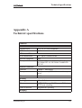
Appendix A
Technical specifications . . . . . . . . . . . . . . . . . . . . . . .
A-1
A.1
Mechanical construction and power supply . . . . . . . . . .
A-3
A.2
Ambient conditions, EMC and safety . . . . . . . . . . . . . . .
Ambient conditions . . . . . . . . . . . . . . . . . . . . . . . . . . . . .
EMC . . . . . . . . . . . . . . . . . . . . . . . . . . . . . . . . . . . . . . . . .
Safety . . . . . . . . . . . . . . . . . . . . . . . . . . . . . . . . . . . . . . . .
A-3
A-3
A-3
A-4
Glossary
C33907001SE_00
E Copyright Nokia Networks Oy
vii
M1112 Administrator Manual
viii
E Copyright Nokia Networks Oy
C33907001SE_00
Introduction to Nokia M1112
Chapter 1
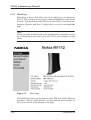
Introduction to Nokia M1112
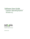
Nokia M1112 is an integrated ADSL (Asymmetric Digital Subscriber
Line) bridge and router which enables high-speed Internet access for
your Ethernet local area networks (LAN). It multiplies the capacity of
the already installed telephone lines used for ISDN services. M1112
brings high-speed connections available for home users, small offices
and telecommuters.
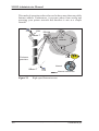
Figure 1-1
Nokia M1112
M1112 allows you to connect your desktop and laptop PCs to remote
networks. Your PCs must be equipped with a 10Base-T Ethernet
interface. M1112 has an in-built 4-port hub, which allows easy home
network installation.
The ADSL high-speed Internet access may be delivered to you over
the same copper pair of wires that is used for your ISDN services. As
C33907001SE_00
E Copyright Nokia Networks Oy
1-1
M1112 Administrator Manual
both services utilise the same pair of wires, a filter is needed to separate
them. This is called an ISDN filter and it is a small external device
connected between your telephone and the telephone wall socket.
Your Nokia M1112 interconnects with a Digital Subscriber Line
Access Multiplexer (DSLAM) installed and maintained by your
access provider in their central office. M1112 ADSL technology is
based on Discrete Multitone (DMT) modulation allowing a maximum
of 8 Mbit/s data transmission from the network and 800 kbit/s towards
the network. However, these figures illustrate the maximum
performance of the technology and are subjected to the physical line
conditions and the distance from you to the central office. M1112 is
capable of adapting to the physical line conditions and guarantees the
maximum transmission rate possible on the particular line. M1112
adapts its speed to the line conditions in steps of 32 kbit/s. In addition
to these physical limitations affecting your data throughput, your
Internet Service Provider (ISP) may limit your access according to
their service provisioning policy and based on your service contract.
1-2
E Copyright Nokia Networks Oy
C33907001SE_00
Applications and features
Chapter 2
Applications and features
In this chapter, we present the most common applications and features
of M1112. The use and configuration of your Nokia M1112 may be
different from the configurations presented in this manual, even for
similar applications. The configurations presented in this manual
represent a typical way of using M1112 for the corresponding
applications.
2.1
Applications
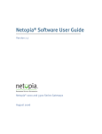
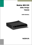
The three typical applications discussed below are the Internet access,
remote work, and office LAN interconnection.
Internet access
Your access to the Internet is provided by your Internet Service
Provider (ISP). Nokia M1112 connects you through your telephone
line and the ATM (Asynchronous Transfer Mode) network to the
network of your ISP, which, in turn, is connected to the Internet.
Hence, all your data goes through the ISP’s network. If you are using
only one ISP for your Internet access, your ISP may give you a limited
set of IP addresses belonging to its address space that you may utilise
in your desktop and laptop computers on your home network.
However, in many cases it is more practical to separate your own
private LAN from the ISP’s public network by using private IP
addresses. This way you are not limited to the number of public IP
addresses provided by your ISP but you can manage your own address
space independently. For this you will need to use NAPT (Network
Address Port Translation) feature available in your M1112 modem.
C33907001SE_00
E Copyright Nokia Networks Oy
2-1
M1112 Administrator Manual
This mode of operation reduces the need to have more than one public
Internet address. Furthermore, it prevents others from seeing and
accessing your private network and therefore it acts as a simple
firewall.
LAN
DSLAM
10Base-T
ATM
network
RAN
Customer
premises
Internet
10Base-T
Internet connection
Figure 2-1
2-2
High-speed Internet access
E Copyright Nokia Networks Oy
C33907001SE_00
Applications and features
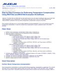
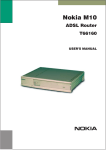
Remote work
Another application for M1112 is remote work. In this case the
end-to-end architecture can, for example, use PPP over Ethernet,
where a dial-up-type PPP connection is created between your home PC
and your corporate networks PPP access server based on the user name
and password you issue in your PC. The same set up could be used for
accessing the public Internet with a different user name and password.
This example naturally presumes that your ISP supports this type of
approach for providing remote work services for our company.
Remote
worker 1
DSLAM
ATM
network
10Base-T
Nokia M1112
Remote
worker 2
RAN
PPPoE
L2TP
Company
router
Corporate
network
Remote
worker 3
Figure 2-2
C33907001SE_00
Remote work using M1112 as a standard router
E Copyright Nokia Networks Oy
2-3
M1112 Administrator Manual
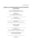
LAN interconnection
M1112 can also be used for corporate branch office LAN
interconnection. As a bridge, M1112 enables all network protocols to
be used on the corporate network.
LAN
10Base-T
DSLAM
ATM
network
Remote
office 1
Remote
office 2
Company
bridge
Remote
office 3
10Base-T
Figure 2-3
2.2
Corporate
network
LAN interconnection
Features
M1112 can operate as a bridge and/or Internet Protocol (IP) router
between the Ethernet and the virtual channels of ADSL/ATM
interfaces supporting both dynamic and static routing.
2.2.1
Interfaces
M1112 has the following interfaces:
D
D
D
2-4
Four Ethernet interfaces (LAN)
8 ATM VCC interfaces
ATM VCC management interface
E Copyright Nokia Networks Oy
C33907001SE_00
Applications and features
D
Gateway/bridge management interface. This interface is used as a
bridge host interface or gateway interface depending on the
operation mode. In this manual it is called VBRIDGE. On the
M1112 web pages, the interface is called gateway or bridge IP
interface.
M1112 can operate in four different main modes:
D
D
D
D
Bridging only
Routing/tunneling IP only
Routing/tunneling IP, bridging all but IP
Routing/tunneling IP and bridging all, including IP
The mode in which M1112 operates depends on the configuration of
the unit’s interfaces. Table 2-1 shows the operational modes and the
corresponding interface configurations.
LAN interface
ATM VCC interfaces
Vbridge
(gateway/host interface)
Bridge only
Bridging
Bridging.
Used as a management (host) interface
for all bridged interfaces in case such is
needed.
Route/tunnel IP only
Routing (IP address
configured)
C33907001SE_00
Routing (IP address
configured) or PPTP
local tunneling activated for each active
ATM VCC.
E Copyright Nokia Networks Oy
Not used in this case.
The unit can be managed through any of
the LAN or ATM interface IP addresses.
2-5
M1112 Administrator Manual
LAN interface
ATM VCC interfaces
Vbridge
(gateway/host interface)
Route/tunnel IP, bridge all other traffic
Routing (IP address
VCCs that only route
configured) and bridg- or tunnel have routing
ing activated.
(IP address configured) or PPTP local
tunneling activated.
VCCs that both bridge
and route have additionally bridging activated. This requires
ETH-LLC encapsulation to be used on
those VCCs.
VCCs that only bridge
have only bridging
activated.
Typically not used in
this case. The unit
can be managed locally through the LAN
interface and remotely through a separate
management VCC or
the ATM VCCs which
have routing activated.
Route/tunnel IP, bridge all other including IP
Bridging activated
Table 2-1
VCCs that only route Used as an IP gateor tunnel have routing way interface for LAN
(IP address confiinterface.
gured) or PPTP local
tunneling activated.
VCCs that only bridge
have only bridging
activated.
Operational modes
LAN interface
LAN interface can be configured individually to bridge and route
packets. There are three different operational modes in the LAN
interface:
D
D
D
2-6
Bridging only; only bridging is activated in the interface. In this
case the interface bridges all protocols.
Routing only; only IP address is configured in the interface. In this
case, the interface routes IP packets.
Bridging and routing; Bridging is activated in the interface and IP
address is configured in the interface. In this case, the interface
routes IP packets and bridges all other packets.
E Copyright Nokia Networks Oy
C33907001SE_00
Applications and features
Internal host/gateway interface
There is a special host/gateway logical IP interface within M1112
called VBRIDGE. This interface has a specific purpose in M1112. In
applications where some ATM virtual channel connections are used
for bridging IP traffic and some other ATM virtual channel
connections are used for routing IP traffic, the VBRIDGE interface
must be used instead of LAN IP address. Alternatively, this interface is
used in bridge only application when the IP address is required for
remote management purposes.
Data VCC operation
M1112 supports the following encapsulations in each ATM data
virtual channel individually:
D
D
D
D
RFC2684 LLC encapsulation for bridged IP (ETH-LLC)
RFC2684 LLC encapsulation for routed IP (IP-LLC)
RFC2364 Virtual circuit multiplexed PPP over AAL5 (PPP-VC)
RFC2364 Virtual circuit multiplexed PPP over AAL5 used to
tunnel LAN/VBRIDGE PPTP packets
(TUNNELED-PPP-VC)
If an IP address is given to a virtual channel interface and bridging is
enabled at that interface, then IP data at that interface is routed and all
other protocols are bridged. The only encapsulation which allows both
bridging and routing simultaneously is ETH-LLC. For example, it is
possible to route ETH-LLC encapsulated packets and at the same time
bridge, for example, PPPoE packets (PPPoE packets are transported
directly over Ethernet frame, not within IP packets).
2.2.2
Routing
Routing is based on routing entries in a routing table. Static routes are
added via the management interface and dynamic routing is done using
RIP and RIPv2. Routing is done between the Ethernet 10Base-T
interface and the virtual channel connection (VCC) of the ATM/ADSL
interface. M1112 supports up to 8 simultaneous VCCs.
M1112 supports IGMP (Internet Group Management Protocol) proxy
receive function for IP multicast applications.
2.2.3
Bridging
Bridging is supported to provide full protocol transparency. Bridging
can be used simultaneously with IP routing. M1112 works as a
C33907001SE_00
E Copyright Nokia Networks Oy
2-7
M1112 Administrator Manual
self-learning bridge supporting up to 1024 MAC addresses. Bridging
is done between the Ethernet 10Base-T interface and each ATM VCC
interface. Optionally, the bridging between the VCCs can be disabled.
2.2.4
Network Address Port Translation
M1112 supports Network Address Port Translation (NAPT) for
TCP/IP, UDP/IP and ICMP/IP protocols. When NAPT is used, a single
IP address is allocated to a VCC which leads to the public IP network.
The Ethernet subnet has private IP addressing and is not visible to the
VCC. NAPT translates the IP source address and source port number
dynamically to the VCC IP address and port number. Similarly,
packets coming from the VCC are mapped back to the original
destination addresses. NAPT allows up to hundreds of hosts to share a
single VCC IP address to the public network. The principle of Network
Address Port Translation is presented in Figure 2-4.
src:192.168.1.112:1228
dst:194.112.11.111:80
src:194.112.11.111:80
dst:192.168.1.112:1228
Figure 2-4
NAPT router
195.112.12.161
Internet (WAN)
192.168.1.254
Home network (LAN)
src:195.112.12.161:50001
dst:194.112.11.111:80
src:194.112.11.111:80
dst:195.112.12.161:50001
Principle of Network Address Port Translation
NAPT may restrict the operation of some IP applications. NAPT also
operates as a simple IP firewall because translation is only allowed
when the first packet is transmitted from the LAN. This means that the
NAPT table entry is created only when a packet is sent from the home
network to the Internet. With server support capability, the user can
add static entries to the NAPT table allowing the translation always in
both directions. This capability is used to add servers (HTTP, NNTP,
and FTP), which are visible to the public IP network via the VCC, on
the LAN subnet.
NAPT supports most IP-based protocols. Because NAPT operates on
the IP and transport layer, the application that includes IP address and
port within the payload will not work properly through NAPT. In many
cases, these applications can be passed through the NAPT using
2-8
E Copyright Nokia Networks Oy
C33907001SE_00
Applications and features
Application Layer Gateway functionality (ALG). M1112 has ALG for
the following protocols/applications:
D
D
D
D
D
D
D
ICMP
FTP
H.323 including NetMeeting
CUSeeMe
PPTP
IRC
IPSEC ESP tunnel mode and IKE
Note, that most IPSEC implementations will fail when passed through
NAPT. A typical reason is that the identification may fail if the
identification is based on IP address. Also, only tunnel mode without
Authentication Header (AH) works.
2.2.5
Dynamic Host Configuration Protocol
M1112 can act as a Dynamic Host Configuration Protocol (DHCP)
server for the PCs on the end-user home network. In this mode, M1112
can assign up to 253+253 consecutive addresses from two separate
address ranges (that is, 253 consecutive addresses per address range)
to the PCs on the home network. Two separate address ranges can be
used if more than 253 addresses are required on the local subnet, if two
non-contiguous ranges are needed or if an additional router with
DHCP relay is used on the local network. M1112 can also act as a
DHCP relay agent and relay the DHCP requests to an external DHCP
server.
2.2.6
ATM and ADSL
M1112 supports up to 8 simultaneous VCCs and supports UBR
(Unspecified bit rate) traffic shaping on all VCCs. The maximum
transmit rate on each VCC is the ADSL upstream capacity. If more
than one VCC is transmitting simultaneously, the ADSL upstream
capacity is temporarily shared between these VCCs. When one VCC is
idle, the bandwidth is used by another VCC.
The ADSL transmission is based on the DMT line code. M1112
provides a DMT line rate up to 8 Mbit/s downstream and up to 800
kbit/s upstream. The DMT transceiver is rate adaptive and capable of
providing faster rates over short distances or slower rates over long
distances. The transceiver adapts itself to the line conditions.
M1112 is compatible with ETSI 101 388.
C33907001SE_00
E Copyright Nokia Networks Oy
2-9
M1112 Administrator Manual
Rate adaptation is done in steps of 32 kbit/s. The ADSL interface of
M1112 functions completely automatically and all configuration
related to the ADSL connection is done at the access multiplexer in the
operator’s premises. The network operator can set the data rates as a
part of the network management functionality provided by Nokia
DSLAM.
2.2.7
Point-to-Point Tunneling Protocol (PPTP)
When PPTP local tunneling is used, a local network client initialises a
PPTP-tunneled PPP connection (VPN) to Nokia M1112. The modem
terminates the tunnel and all data from that terminated local PPTP
tunnel will be forwarded to an assigned ATM VCC by using PPP over
AAL5 encapsulation. Thus, each local PPTP tunnel requires an
equivalent ATM VCC assigned to it restricting the total number of
local PPTP hosts to 8.
Local tunneling is used when there is a need to have one or more
computers connected independently to different networks. For
example, in remote work application, the rest of the family may be
using the common ISP services and one or two family members need to
gain access to their corporate networks. With local tunneling, these
remote workers may be connected to a different network than the rest
of the users.
Local tunneling is activated using the PPTP client running, for
example, in Windows The destination IP address must be M1112
LAN/VBRIDGE IP address depending on the configuration. PPP
packets within PPTP are mapped to the configured VCC. M1112 has
three different ways to choose the ATM VCC that will be used for
tunneling:
D
D
D
2-10
Automatic, chooses the first free VCC
Chooses the VCC number using C:number, where number is from
1 to 8. C:number is typed after the M1112 IP address in PC’s PPTP
client Connect To window (see Figure 2-5).
Chooses the VCC number using N:name, where name is the
VCCx description. N:name is fed after the M1112 IP address.
E Copyright Nokia Networks Oy
C33907001SE_00
Applications and features
Figure 2-5
2.2.8
Choosing the VCC2 for tunneling example
Point-to-Point Protocol over Ethernet (PPPoE)
Standard PPPoE mode is used when M1112 is operating as a bridge.
PPPoE protocol defines how PPP sessions are mapped into Ethernet
packets. When M1112 operates as a bridge, this protocol is transparent
to M1112.
2.2.9
Payload encapsulations
Both routed and bridged protocols are encapsulated in the ATM link by
using either RFC 2684 LLC/SNAP encapsulation or VC multiplexing.
M1112 also supports PPP over AAL5 encapsulation, in which routed
protocols are first encapsulated in PPP (RFC 1661). PPP is then
encapsulated in ATM according to the IETF PPP over AAL5 using
RFC 2364 VC multiplexing or LLC/NLPID encapsulation.
2.2.10 Weighted Fair Queueing (Class of Service)
As a Class of Service (CoS) function, M1112 supports Weighted Fair
Queueing (WFQ) for each ATM VCC. The CoS function ensures that
different IP traffic flows are treated fairly in the upstream (towards the
Internet) direction. This may be necessary, in some cases, because the
upstream capacity of the ADSL line is somewhat limited compared to
the Ethernet bandwidth on the office or home LAN. The WFQ CoS
C33907001SE_00
E Copyright Nokia Networks Oy
2-11
M1112 Administrator Manual
function classifies IP traffic flows based on IP address, protocol and
port fields. It is capable of identifying the IP flow from all supported
payload encapsulation formats. WFQ works properly only with
IP-based protocols. If the flow is IP-based but is encrypted using IPSec
or PPP encryption, then WFQ cannot identify the flows correctly. In
this case, the default flow is used and the default flow is treated as a
single flow.
2.2.11 Management
There are three management methods in M1112:
D
D
D
Command line interface (CLI) through console serial port
CLI via telnet
Web browser management
The CLI allows complete configuration of the unit; the Web browser
management allows the configuration of the most frequently used
configuration parameters.
2.2.12 Dedicated management channel
The operator or the Internet Service Provider can establish a dedicated
management channel to M1112. This channel provides access to the
M1112 management (with telnet or web browser) and it can be used to
upload a new software to M1112.
The dedicated management channel is separated from the other IP
stack. It is not possible to access the other interfaces or networks
behind the data interfaces through the dedicated management channel.
Similarly, access from LAN or data VCCs to the management channel
is blocked. The management channel supports only routing using the
following encapsulations:
D
D
D
RFC2684 LLC encapsulation for bridged IP (ETH-LLC)
RFC2684 LLC encapsulation for routed IP (IP-LLC)
RFC2364 Virtual circuit multiplexed PPP over AAL5 (PPP-VC)
In Figure, 2-6 VCC1 is used for customers data transmission.
Administration through this channel has been disabled. The operator
or the service provider uses the management VCC for management
purposes only.
2-12
E Copyright Nokia Networks Oy
C33907001SE_00
Applications and features
LAN
VCC1/Data
(admin disabled)
Internet
10Base-T
Home
network
Nokia M1112
ISP’s NMS Network
management system
Figure 2-6
C33907001SE_00
Management VCC
Dedicated management channel
E Copyright Nokia Networks Oy
2-13
M1112 Administrator Manual
2-14
E Copyright Nokia Networks Oy
C33907001SE_00
Interfaces and indicator lights
Chapter 3
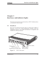
Interfaces and indicator lights
This chapter describes the external interfaces of M1112 and introduces
its front panel indicator lights.
3.1
Interfaces
M1112 has one ADSL line interface and one LAN interface (10Base-T
Ethernet). It also has a local management interface (CLI) for
management purposes. The ADSL line interface is compatible with
ETSI TS 101 388 specification.
Power switch
Mains connector
Command line interface (CLI)
Figure 3-1
C33907001SE_00
ADSL line (DSL)
Ethernet ports
(ETH-1, ETH-2,
ETH-3, ETH-4)
M1112 back panel
E Copyright Nokia Networks Oy
3-1
M1112 Administrator Manual
3.1.1
Ethernet interface
The Ethernet interface (ETH) is located on the back panel. The
Ethernet interface is a standard 10 Mbit/s half-duplex 10Base-T
interface. The mechanical connector is an 8-pin RJ-45. The pin-out
numbering is shown in Table 3-1.
1
8
Figure 3-2
PIN
Signal
Direction
M1112Ethernet
1
2
3
6
Rx+
Rx–
Tx+
Tx–
<–
<–
–>
–>
Table 3-1
3.1.2
ETH connector
MDI signal
Receive data +
Receive data –
Transmit data +
Transmit data –
Ethernet interface pin-out numbering
ADSL interface
The ADSL interface (DSL) is compatible with ETSI TS 101 388
specification. The mechanical connector is a 6-pin RJ-11. The pin-out
numbering is shown in Table 3-2.
1
6
Figure 3-3
3-2
DSL connector
E Copyright Nokia Networks Oy
C33907001SE_00
Interfaces and indicator lights
Table 3-2
3.2
PIN
Signal
3
4
DSL1
DSL2
ADSL interface pin-out numbering
Command line interface
The command line interface (CLI) is RS-232 interface with an RJ-45
mechanical connector. The pin-out numbering is shown in Table 3-3.
1
8
Figure 3-4
CLI connector
PIN
Signal
Direction
M5112-terminal
1
107 DSR
(const. ON)
108 DTR
109 DCD
(const. ON)
–>
Data set ready
<–
–>
<–
–>
<–
Data terminal ready
Data channel received line signal detector
Signal ground
Transmitted data
Received data
Request to send
–>
Clear to send
2
3
4
5
6
7
8
Table 3-3
C33907001SE_00
102 SG
103 TxD
104 RxD
105 RTS
(not in use)
106 CTS
(const. ON)
MDI signal
Command line interface pin-out numbering
E Copyright Nokia Networks Oy
3-3
M1112 Administrator Manual
3.3
Indicator lights
M1112 has eight indicator lights on the front panel: PWR, STA, COL,
ETH-1, ETH-2, ETH-3, ETH-4, and DSL. STA indicator is red. Other
indicators are green.
Figure 3-5
DSL
Off
Blinks
On
ETH-
Off
On
Blinks
COL
Blinks
3-4
M1112 front panel indicators
GREEN
ADSL link is down.
ADSL connection is being established.
ADSL link is up.
GREEN
Ethernet is down.
10Base-T Ethernet is functional
Receives traffic from Ethernet.
GREEN
Collisions on the Ethernet. Note, that it is normal that some
collisions occur on the Ethernet.
E Copyright Nokia Networks Oy
C33907001SE_00
Interfaces and indicator lights
STA
Off
On
PWR
Off
On
C33907001SE_00
RED
OK
Hardware malfunction during startup.
GREEN
Power off.
Power on.
E Copyright Nokia Networks Oy
3-5
M1112 Administrator Manual
3-6
E Copyright Nokia Networks Oy
C33907001SE_00
Installing Nokia M1112
Chapter 4
Installing Nokia M1112
This chapter presents a step-by-step installation procedure of M1112.
Before starting the installation check that M1112 is physically
undamaged. The package contains the following items:
D
D
D
D
D
D
4.1
M1112 modem
ADSL line cable
Straight 10Base-T Ethernet cable
power cord
serial adapter
User Manual
M1112 default settings
Typically, M1112 has a customer-specific configuration. The default
configuration of a general version is shown in Table 4-1.
C33907001SE_00
E Copyright Nokia Networks Oy
4-1
M1112 Administrator Manual
Config mode level
Parameter
Setting
system
hostname
M1112
eth
IP address
192.168.1.1
255.255.255.0
vcc1
pvc
0 (vpi) 100 (vci)
ppp-vc (encaps)
IP address
0.0.0.0 0.0.0.0,
means that M1112
gets its IP address
dynamically from the
network.
IP NAPT
on
ppp authentication
both-chap-pap
ppp username
none
ppp password
none
ip route
0.0.0.0 0.0.0.0 0.0.0.0
vcc1
DHCP mode
server
common
Table 4-1
4-2
M1112 default settings
E Copyright Nokia Networks Oy
C33907001SE_00
Installing Nokia M1112
4.2
Step-by-step installation procedure
1. Plug the mains power cord to a mains outlet.
2. Switch on M1112. The PWR indicator lights up.
3. Connect the 8-pin Ethernet cable between your PC’s 10 Base-T
Ethernet card and the Ethernet connector on the M1112 back
panel.
4. Switch on your PC. The indicator corresponding the Ethernet port
you connected your PC to becomes green when your PC has
started. This indicator blinks when there is traffic in the
corresponding Ethernet port.
5. Connect the 6-pin ADSL line cable between the ADSL connector
on the M1112 back panel and your ADSL line wall socket. If you
want to use ISDN and ADSL data services simultaneously,
connect a splitter according to Figure 4-1. After a while, the DSL
indicator starts blinking indicating that the ADSL connection is
being established. After the connection has been established
successfully the DSL indicator remains lit.
6. During normal operation PWR and DSL indicators are lit and the
Ethernet indicators of the active Ethernet ports blink or are lit
depending whether there is traffic or not. COL indicator may blink
occasionally during normal operation.
S int.
ISDN NT1
U int.
splitter
Figure 4-1
M1112 and splitter connected
Now, your M1112 has been connected and you can check the
connections according to your service provider’s instructions. See
C33907001SE_00
E Copyright Nokia Networks Oy
4-3
M1112 Administrator Manual
Chapter 5 Managing M1112 for instructions on how to configure
M1112.
4-4
E Copyright Nokia Networks Oy
C33907001SE_00
Managing M1112
Chapter 5
Managing M1112
This chapter shows some operational examples of M1112. The
examples can be used as a guide when you are planning your
configuration. After the operational examples, we introduce the
management methods of M1112. First we show how to use the web
browser management and then the command line interface (CLI) will
be presented. The command line interface section contains all CLI
commands.
5.1
Operational examples
This section presents some typical operational examples and the
corresponding configurations. Figure 5-1 shows a general block
diagram of the IP forwarding and bridging functions of M1112.
C33907001SE_00
E Copyright Nokia Networks Oy
5-1
M1112 Administrator Manual
IP-HOST or IP-FORWARD-STACK
(Routing or NAPT routing or tunneling)
VCC8
VCC7
VCC6
VCC5
VCC4
VCC3
VCC2
VCC1
VBRIDGE
LAN
Bridge/
IP
LAN
Bridge/ Bridge/ Bridge/ Bridge/ Bridge/ Bridge/ Bridge/ Bridge/
IP
IP
IP
IP
IP
IP
IP
IP
VCC1 VCC2 VCC3 VCC4 VCC5 VCC6 VCC7 VCC8 MNGT
Figure 5-1
5.1.1
MNGTVCC
Bridge group
Bridging between interfaces connected to Bridge group. VBRIDGE
interface is the common IP interface for all bridge only interfaces
Block diagram
Routing/tunneling IP only
If the application requires only routing of IP packets, an IP address
should be configured for each interface in use. The example below
shows a typical configuration in such a case.
M1112> show conf running
eth
ip address 192.168.1.1 255.255.255.0
vcc1
pvc 0 101 ip-llc
ip address 10.98.16.1 255.255.255.0
M1112>
5.1.2
Routing/tunneling IP, bridging other protocols
When the application requires routing IP packets and bridging all other
protocols, then IP address has to be configured and bridging enabled
5-2
E Copyright Nokia Networks Oy
C33907001SE_00
Managing M1112
for all relevant interfaces. The result is that IP packets will be routed
and all other packets will be bridged. In the configuration example
below, LAN interface routes IP traffic and bridges all other protocols.
ATM VCC1 routes IP traffic and ATM VCC2 interfaces bridges all
traffic.
M1112> show config running
eth
ip address 192.168.1.1 255.255.255.0
bridging
vcc1
pvc 0 101 ip-llc
ip address 10.98.16.1 255.255.255.0
vcc2
pvc 0 102 eth-llc
bridging
M1112>
5.1.3
Routing/tunneling IP, bridging all protocols including IP
When IP packets that are received from LAN must be routed/tunneled
to some ATM VCC and bridged to some other ATM VCC, then the
VBRIDGE interface must be used as this common IP interface for all
bridged interfaces. LAN interface is in this case configures as bridge
only.
M1112> show config running
eth
bridging
vcc1
pvc 0 101 ip-llc
ip address 10.98.16.1 255.255.255.0
vcc2
pvc 0 102 tunneled-ppp-vc
vcc3
pvc 0 103 eth-llc
bridging
vbridge
ip address 192.168.1.1 255.255.255.0
M1112>
C33907001SE_00
E Copyright Nokia Networks Oy
5-3
M1112 Administrator Manual
5.1.4
Bridging only
When only bridging is required, all ATM VCCs are configured as
bridge. VBRIDGE IP address can be used as an optional management
interface.
M1112> show config running
eth
bridging
vcc1
pvc 0 101 eth-llc
bridging
vcc2
pvc 0 102 eth-llc
bridging
vbridge
ip address 192.168.1.1 255.255.255.0
M1112>
5.2
Typical configuration tasks
This section provides some typical configuration tasks. These
configuration examples can be done through the command line
interface.
Note
After you have made changes to the configuration, you must save the
configuration if you want it to be active also after restarting M1112.
5.2.1
Configuring DHCP and DNS
The DHCP server can be enabled towards LAN and VBRIDGE ports.
When the DHCP server is enabled, up to two address ranges (scopes)
will be automatically generated and bound to LAN/VBRIDGE
interfaces, in this order, if the interface has an IP address. Two separate
address ranges can be used if more than 253 addresses are required on
the local subnet, if two non-contiguous adress ranges are needed or if
an additional router with DHCP relay is used on the local network.
The address range defines pool of IP addresses and parameters like
default gateway, DNS addresses and domain name. The generated
default address range allows up to 253 IP addresses (C class).
5-4
E Copyright Nokia Networks Oy
C33907001SE_00
Managing M1112
Automatically generated address ranges use LAN/VBRIDGE IP
address as gateway and DNS server addresses. If one address range is
defined, then automatic binding will be disabled. If optional address
range parameters like gateway or DNS addresses are not defined,
LAN/VBRIDGE IP addresses are used as in automatic binding.
Typically, when DHCP is used, the advertised DSN addresses point to
LAN/VBRIDGE interfaces. In such cases, the DNS proxy forwards
the DNS request to statically configured DNS servers or to DNS
servers learned dynamically vie PPP/IPCP.
The following commands are used to configure DHCP and DNS
settings:
M1112(conf-common)#dhcp?
usage: dhcp mode
dhcp address
dhcp gateway
dhcp dns
dhcp lease-time
dhcp domain-name
M1112(conf-common)#dhcp mode server ; this enables
DHCP server
Normally, there is no need to configure the DNS addresses. If the
service provider does not support automatic DNS address allocation,
the DNS servers can be configured as shown by the following
example:
M1112(conf-common)# dns address primary 1.2.3.4
M1112(conf-common)# dns address secondary 1.2.3.5
M1112(conf-common)#
5.2.2
Configuring static and dynamic routing
Routing entries in the routing table are needed in order to forward the
IP packets to the correct interface. M1112 has both static and dynamic
routes. Static routes are configured manually and dynamic routes are
learned automatically using RIP v1 and RIP v2 protocols. The
following examples show how to configure static routes to M1112.
Default gateway for an interface that learns the next hop automatically:
M1112(conf-common)# ip route 0.0.0.0 0.0.0.0 0.0.0.0
vcc1
C33907001SE_00
E Copyright Nokia Networks Oy
5-5
M1112 Administrator Manual
Default gateway for an interface that requires static next hop:
M1112(conf-common)# ip route 0.0.0.0 0.0.0.0 1.2.3.1
vcc1
Static route for an interface that learns the next hop automatically:
M1112(conf-common)#
ip
255.255.255.0 0.0.0.0 vcc1
route
131.132.133.0
Static route for an interface that requires a static next hop:
M1112(conf-common)#
ip
255.255.255.0 1.3.5.1 vcc1
route
131.132.133.0
M1112 can have only one default gateway. The interfaces that can
learn gateway/peer address dynamically can use value 0.0.0.0 instead
of the next hop address.
5.2.3
File system and downloading new firmware using TFTP
M1112 has a flash file system. Some files in the file system have
special meanings. These files are:
D
D
D
D
image.exe; primary application file.
image.bak; secondary application file used if image.exe has been
corrupted or is missing. It is then renamed as image.exe
automatically.
startup.cfg; primary configuration file used during startup.
dhcp.leases; contains DHCP lease table information.
M1112 has the following commands that can be used for file handling:
D
D
D
D
copy
rename
delete
dir
If you use image.exe as a destination filename with the copy command
and the image.exe already exists, the existing image.exe will be
automatically renamed as image.bak. This guarantees that the
application file exists if M1112 loses power during SW download.
You can update the operating software of M1112 by downloading the
new software from a TFTP server. To download and activate new
M1112 operating software:
5-6
E Copyright Nokia Networks Oy
C33907001SE_00
Managing M1112
1. Use CLI to issue
install
tftp:/<ip-address>/Gx1x2200.R00 command,
where <ip-address is the IP address of the TFTP server
containing the new software and Gx1x2200.R00 is the name of the
file
to
be
downloaded.
The
command
copy
tftp:/<ip-address>/Gx1x2200.R00 image.exe can be used
alternatively.
SUCCESSFUL
2. After you will see transfer status
message, restart M1112 to activate the new software.
Downloading configuration or application from monitor
Monitor is a small application that is executed before the actual
software image is started. Typically the Monitor automatically loads
the application file image.exe. You can activate the Monitor by
pressing “m” followed by “o” in the very beginning of the system
startup:
local MAC=00:40:43:02:36:72; Using M111/850 eth conf
Type ’m’ (fast) followed by ’o’ (in 10 sec) to
activate Monitor
Nokia Networks (C) 1999
Nokia Boot
B-R0.0.0. built on Apr 4 2000 11:27:55
MON>
The following commands are available for file handling in the
Monitor:
D
D
D
rename
delete
dir
M1112 has two methods of retrieving files:
D
D
TFTP
XMODEM
You can retrieve files from a TFTP server using the commands in the
following example:
MON>ipa 192.168.1.1
ip=192.168.1.1
ipserver=0.0.0.0
ipgw=0.0.0.0
serverfile=
MON>ips 192.168.1.100
C33907001SE_00
E Copyright Nokia Networks Oy
5-7
M1112 Administrator Manual
ip=192.168.1.1
ipserver=192.168.1.100
ipgw=0.0.0.0
serverfile=
MON>file startup.cfg
ip=192.168.1.1
ipserver=192.168.1.100
ipgw=0.0.0.0
serverfile=startup.cfg
MON>eget
tftp loader
ip=192.168.1.1
ipserver=192.168.1.100
ipgw=0.0.0.0
serverfile=startup.cfg
loading file...
file size=556
MON>wri startup.cfg
Writing successful
MON>
A file can also be transmitted from an XMODEM1K running in a PC,
for example, as in the following example:
MON>xget
Start Xmodem1k sending...
MON>wri image.exe
Writing successful
MON>
5.3
Browser management
M1112 can be managed with a web browser or command line interface
(CLI). The web configuration pages of M1112 can be accessed
through the Ethernet or through the ADSL/ATM channels of M1112.
In order to access the web management feature, the IP functionality
must be activated and an IP address must be given to the corresponding
interface.
You can use your PC’s web browser software to access the web
configuration pages in M1112. To access the web pages you must
know the IP address of your M1112 or, alternatively, the “name” that
your M1112 recognises.
5-8
E Copyright Nokia Networks Oy
C33907001SE_00
Managing M1112
Note
Before using your web browser for configuration, you must know the
IP address or the name assigned to your M1112.
There are three ways to find out whether to use a name or an IP
address:
D
D
D
5.3.1
Your service provider has given you an IP address for M1112.
Your M1112 uses Dynamic Host Configuration Protocol (DHCP)
and Domain Name Server. In this case the name is M1112.
Your M1112 uses DHCP. In this case run winipcfg.exe (Windows
95) or ipconfig.exe (Windows NT). The IP address of M1112 is the
Default Gateway address shown by the ipconfig program.
Opening a connection
To open a connection to the Nokia M1112:
1. Start your web browser.
2. Enter the name (’M1112’) or IP address of your Nokia M1112 in
the browser’s Open Location field and press Enter. If you use the
IP address, it has to be assigned to a local port or gateway interface
(VBRIDGE).
3. Type in the username/password as requested. If no
username/password is required, just click OK to proceed. The
Nokia M1112 Main Page appears.
C33907001SE_00
E Copyright Nokia Networks Oy
5-9
M1112 Administrator Manual
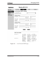
5.3.2
Main Page
Main Page is shown first when you use a web browser to connect to
M1112. The currently shown page is shown highlighted on the list on
the left. Clicking an item on the list (Service Providers, Local Network,
Statistics, Restart, and Save Config) takes you to the corresponding
page.
Note
When you make modifications to the configuration, remember to save
the configuration and restart your M1112 for your changes to take
effect.
Figure 5-2
Main Page
The Main Page shows you the statuses of the DSL line and the Ethernet
interface. Software and hardware versions and the serial number of
M1112 are shown in the bottom of the page.
5-10
E Copyright Nokia Networks Oy
C33907001SE_00
Managing M1112
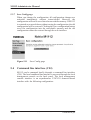
5.3.3
Service Providers pages
The Service Providers page can be used to set authentication for ATM
VCCs with PPP encapsulation (Figure 5-3). You can set the
Authentication method and the corresponding Username and
Password. You can also view Network connection information in the
bottom of the page. If you are using PPTP encapsulation, you can
change the name of the connection through the Service Providers page
(Figure 5-4). The name can be used in your PPTP client for tunnel
configuration, see section 2.2.7 Point-to-Point Tunneling Protocol.
Figure 5-3
C33907001SE_00
Service Providers page with PPP configuration
E Copyright Nokia Networks Oy
5-11
M1112 Administrator Manual
Figure 5-4
5-12
Service Providers page with PPTP configuration
E Copyright Nokia Networks Oy
C33907001SE_00
Managing M1112
5.3.4
Local Network pages
The Local Network page as four sub pages: Local ports, DHCP, NAPT,
and Routing.
Local ports
On the Local Network Local Ports sub page you can assign an IP
address to the Ethernet port.
Note
When you click Apply, the IP addresses are changed immediately. If
the IP address of the interface you are using changes the connection
will be lost. You have to reconfigure the IP address of the accessing
host. For example, in Windows programs winipcfg.exe or
ipconfig.exe must be used first to release the old address and then to
renew to request new address.
Figure 5-5
Local Network Local Ports page
DHCP
On the Local Network DHCP subpage you can enable/disable
Dynamic Host Control Protocol and set the Address ranges from
which the addresses are distributed to the DHCP clients on your
network. You can also set the Domain Name Server addresses here.
C33907001SE_00
E Copyright Nokia Networks Oy
5-13
M1112 Administrator Manual
Start address is the first address in the address range. The Range size
defines how many addresses the range contains. Subnet mask is the
subnet mask of the addresses in the range. Primary and Secondary
DNSs set the domain name servers for the corresponding address
range. Lease time defines how often the DHCP client must renew its
lease. Domain name defines the domain name for the range.
The DHCP server can be enabled towards LAN and VBRIDGE
(gateway interface) ports. When the DHCP server is enabled, up to two
scopes (address ranges) are automatically generated and bound to
LAN/VBRIDGE interfaces, in this order if the interface has an IP
address. In Figure 5-6, scope (a) has been bound to Ethernet interface
and scope (b) to VBRIDGE interface. When the address ranges are not
defined, M1112 uses the default values for all DHCP parameters. The
default values are:
D
D
D
D
D
D
Start address is the interface IP address
Subnet mask 255.255.255.0
Range size of up to 253 addresses starting from the interface IP
address.
DNS address is the interface IP address
Lease time is 60 minutes
Domain name is null string
If at least one address range has been defined, then IP address, DNS,
domain name and lease time, if defined, override the default values.
5-14
E Copyright Nokia Networks Oy
C33907001SE_00
Managing M1112
Figure 5-6
C33907001SE_00
Local Network DHCP page
E Copyright Nokia Networks Oy
5-15
M1112 Administrator Manual
NAPT
If Network Address Port Translation (NAPT) has been activated,
servers on your local network are not visible outside your network. On
NAPT page, you can configure pinholes through which you can
provide outside access to your web server from the Internet, for
example.
In the example shown in Figure 5-7, a pinhole has been added on the
Server list. This example means that all TCP traffic coming from the
Internet through VCC1 to ports 80...89 will be mapped to the IP
address 192.168.1.15 ports 90...99 on your local network.
Figure 5-7
5-16
Local Network NAPT page
E Copyright Nokia Networks Oy
C33907001SE_00
Managing M1112
Routing page
On the Local Network Routing sub page you can set static routes and
enable/disable dynamic routing protocols (Routing Information
Protocol version 1 and 2).
To enable dynamic routing to a particular interface select the Routing
protocol version from the pull-down list and click the Apply button.
RIP versions 1 and 2 are supported. Send v1-compat. v2 option enables
the sending of RIPv2 packets using broadcast. Receive v1-compat. v2
option enables the receiving of both RIPv1 and RIPv2 packets.
To add a static route, type in the Destination network IP address, the
Subnet mask of the destination network, and the Gateway and the
Interface through which the destination network can be reached. Then
click the Add new button. There are two static routes in Figure 5-8.
Figure 5-8
C33907001SE_00
Local Network Routing page
E Copyright Nokia Networks Oy
5-17
M1112 Administrator Manual
5.3.5
Statistics page
The Statistics page lets you view a selection of M1112 statistics. to
view statistics of a particular function, click the corresponding button
and the statistics view is opened on a separate window.
Figure 5-9
5-18
Statistics page
E Copyright Nokia Networks Oy
C33907001SE_00
Managing M1112
5.3.6
Restart page
On the Restart page, you can reset subsystems and restart M1112.
Figure 5-10
C33907001SE_00
Restart page
E Copyright Nokia Networks Oy
5-19
M1112 Administrator Manual
5.3.7
Save Config page
When you change the configuration, all configuration changes are
activated immediately without restart/reload. However, the
configuration will not be saved into the nonvolatile memory. If M1112
is restarted or powered down without saving the configuration, the old
configuration will be restored. Clicking the Save configuration button
saves the configuration into the nonvolatile memory and the old
configuration cannot be restored through the web interface.
Figure 5-11
5.4
Save Config page
Command line interface (CLI)
M1112 can be managed locally through a command line interface
(CLI). The local command line interface is accessed through the local
management console on the back panel. The local management
console interface is an asynchronous V.24/V.28 character-based
interface with the following configuration:
5-20
E Copyright Nokia Networks Oy
C33907001SE_00
Managing M1112
Setting
Value
Speed
9600
Parity
None
Data bits
8
Stop bits
1
Duplex
Full
Flow control
None
Table 5-1
Local management console configuration
Use the 10Base-T Ethernet cable with the serial adapter to connect you
PC’s serial port to the local management console interface according to
Figure 5-12.
10Base-T
Ethernet cable
serial adapter
Figure 5-12
Local management cabling
The command line interface can also be accessed through the Ethernet
port of M1112 or through the ATM channels of M1112 on top of the
telnet protocol. In order to use the CLI through telnet or the ATM
channel, the IP function must be switched on and IP address must be
given to the corresponding interface.
M1112 can also be managed remotely through a separate ATM virtual
channel. This channel is only used for management purposes. In order
to use this management channel, it has to be activated first and given an
IP address configuration. The management traffic to this interface is
not routed to any other interfaces of M1112.
C33907001SE_00
E Copyright Nokia Networks Oy
5-21
M1112 Administrator Manual
The command line interface has been divided into two modes: main
and configuration. The main mode lets you monitor the status and
performance of M1112. The configuration mode lets you change
M1112 configuration. The CLI is case sensitive. All commands must
be given in lower case characters. Only file names and strings can
contain upper case characters.
In the configuration mode, functions can be activated by typing the
corresponding command, for example bridging. The function can be
deactivated by simply typing no bridging. In commands which
require typing in parameter values, the default value can be restored by
typing de ppp mru, for example. de in front of the command means
“default”. If you type in a value which is incorrect (for example, letters
instead of numbers), the CLI prompts you to enter the value correctly
and displays help. You can always get help on the command or display
by typing help or ? at the command prompt.
You can recall you previous commands by pressing the “up-arrow”
key on your keyboard.
The configuration mode has been divided into levels. You can navigate
through the configuration mode by typing the name of the level. By
typing exit you will return to the main mode. top command returns
you to the root level of the configuration mode (M1112(conf)#).
The configuration mode levels are:
D
D
D
D
D
D
D
system
password
eth
vcc1, vcc2, vcc3, vcc4, vcc5, vcc6, vcc7, and vcc8
vbridge
mngtvcc
common.
The example below shows how to access the different levels:
M1112>
M1112>conf
M1112(conf)#system
M1112(conf-system)#password
M1112(conf-password)#eth
M1112(conf-eth)#vcc1
M1112(conf-vcc1)#vcc2
M1112(conf-vcc2)#vcc3
M1112(conf-vcc3)#vcc4
5-22
E Copyright Nokia Networks Oy
C33907001SE_00
Managing M1112
M1112(conf-vcc4)#vcc5
M1112(conf-vcc5)#vcc6
M1112(conf-vcc6)#vcc7
M1112(conf-vcc7)#vcc8
M1112(conf-vcc8)#vbridge
M1112(conf-vbridge)#mngtvcc
M1112(conf-mngtvcc)#common
M1112(conf-common)#top
M1112(conf)#exit
M1112>
5.4.1
Main mode commands
Command
Show diagnostic log
Description
Displays diagnostic log.
Syntax
show log
Arguments
all
Example
M1112> show log
00/00:00:04 HI(1) ATM chann/vcc1/admin.stat up
M1112>
C33907001SE_00
E Copyright Nokia Networks Oy
5-23
M1112 Administrator Manual
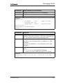
Command
Show DSL line status
Description
Displays DSL line status
Syntax
show dsl [all]
Arguments
all
Example
M1112> show dsl
hardware-type ALCATEL/DMT
hardware-rev
99111601/ISDN/CP
firmware-rev
00002508
activity-statusOPER/FULL
near-end
maximum-bitrate5696kbits
actual-bitrate4608kbits
noise-margin
3.5dB
output-power
12.0dBm
attenuation
48.5dB
corr-fast-fec 0
corr-intl-fec 47
fail-fast-crc 0
fail-intl-crc 0
fail-fast-hec 0
fail-intl-hec 0
flaged-alarms NONE
M1112>
Command
Show Ethernet interface status
Description
Displays Ethernet interface status
Syntax
show eth [all]
Arguments
show eth command shows Ethernet interface state
and status.
all argument shows also interrupts.
Example
M1112> show eth
##eth(up)
stat-tx-payload
stat-rx-payload
M1112>
5-24
far-end
448kbits
416kbits
0.0dB
20dBm
0.0dB
0
0
0
0
0
658
NONE
type
IEEE 802.3/DIX
pkt
oct
dis
10964
672919 0
10968
657690 0
E Copyright Nokia Networks Oy
err
0
0
C33907001SE_00
Managing M1112
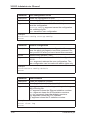
Command
Show ATM status
Description
Displays ATM status.
Syntax
show atm [all]
Arguments
show atm command shows active ATM channels and
traffic statistics.
all shows all ATM information.
Example
M1112> show atm
##vcc1(up) vpi
0
stat-tx-payload
stat-rx-payload
M1112>
vci
35
type
DATA_PVC
encap
ETH-LLC
pkt
oct
dis
223641 2568289 0
18030
1440816 0
err
0
0
Command
Show bridge interface status
Description
Displays interfaces which have bridging enabled.
Syntax
show bridge if
Arguments
None
Example
M1112> show bridge if
VBRI (up)
phys-address
00:99:12:16:10:53
ETH (up)
phys-address
00:00:00:00:00:00
VCC1 (up)
phys-address
00:00:00:00:00:00
M1112>
C33907001SE_00
E Copyright Nokia Networks Oy
5-25
M1112 Administrator Manual
Command
Show bridging statistics
Description
Displays bridging statistics.
Syntax
show bridge stat
Arguments
None
Example
M1112> show bridge stat
in-packet
8518
out-packet
discard
24
M1112>
Command
Show bridging table
Description
Displays bridging table.
Syntax
show bridge table
Arguments
None
Example
M1112> show bridge table
if
phys-address
age
VBRI 00:99:12:16:10:53 n/a
VCC1 00:60:08:94:da:a7 0
ETH 00:60:08:94:af:d7 0
nr-of-entries 3
M1112>
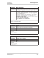
Command
Show PPTP information
Description
Displays PPTP information
Syntax
show pptp
Arguments
None
Example
M1112>show pptp
VCC3 net-address
n/a
description
Office
M1112>
5-26
port status
n/a IDLE
E Copyright Nokia Networks Oy
8494
type
forever
dynamic
dynamic
host-cid peer-cid
n/a
n/a
C33907001SE_00
Managing M1112
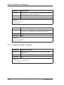
Command
Show Address Resolution Protocol (ARP) table
Description
Displays ARP table.
Syntax
show ip arp
Arguments
None
Example
M1112>show ip arp
VBRIDGE
net-address
10.98.20.140
M1112>
phys-address
00:00:0e:7c:15:d4
Command
Show IP interfaces
Description
Displays IP interfaces.
Syntax
show ip if
Arguments
None
Example
M1112> show ip if
VBRIDGE (up)
net-address
net-mask
192.168.172.2 255.255.255.0
as ETHERNET/RIP DISABLED
M1112>
C33907001SE_00
age
00.07
mtu phys-address
1500 00:99:12:16:10:53
E Copyright Nokia Networks Oy
5-27
M1112 Administrator Manual
Command
Show IP statistics
Description
Displays IP statistics.
Syntax
show ip stat
Arguments
None
Example
M1112> show ip stat
forwarding NO FORWARD
default-ttl
255
in-receives
2355
in-hdr-errors
0
in-addr-errors
1
forw-datagrams
0
in-unknown-protos 0
in-discards
2354
in-delivers
2354
out-requests
0
M1112>
out-discards 0
out-no-routes 0
reasm-timeout 5
reasm-reqds
0
reasm-OKs
0
reasm-fails
0
frag-OKs
0
frag-fails
0
frag-creates 0
routing-discards0
Command
Show IP cache table and statistics
Description
Displays IP cache table and statistics.
Syntax
show ip cache
Arguments
None
Example
M1112> show ip cache
if
net-address phys-header
ETH 192.168.1.3 005004b67d680040430236720800
ETH 192.168.1.2 005004b669750040430236720800
VCC2 10.98.16.250 0021
nr-of-entries
3
M1112>
5-28
E Copyright Nokia Networks Oy
C33907001SE_00
Managing M1112
Command
Show IP routing table
Description
Displays IP routing table.
Syntax
show ip route
Arguments
None
Example
M1112>show ip route
VBRIDGE
route-dest route-mask
10.98.20.255255.255.255.255
10.98.20.150255.255.255.255
10.98.20.0 255.255.255.0
MNGTVCC
route-dest route-mask
10.98.9.0
255.255.255.0
10.98.5.255 255.255.255.255
10.98.5.100 255.255.255.255
10.98.5.0
255.255.255.0
ETH
route-dest route-mask
10.98.0.255 255.255.255.255
10.98.0.254 255.255.255.255
10.98.0.0
255.255.255.0
VCC3
route-dest route-mask
11.22.20.255255.255.255.255
11.22.20.108255.255.255.255
11.22.20.0 255.255.255.0
0.0.0.0
0.0.0.0
M1112>
C33907001SE_00
netxthop
tag
255.255.255.255BCAST
10.98.20.150 IFACE
10.98.20.150 LOCAL
netxthop
tag
10.98.5.200
RIP
255.255.255.255BCAST
10.98.5.100
IFACE
10.98.5.100
LOCAL
netxthop
tag
255.255.255.255BCAST
10.98.0.254
IFACE
10.98.0.154
LOCAL
netxthop
tag
255.255.255.255BCAST
11.22.20.108 IFACE
11.22.20.108 LOCAL
11.22.20.1
STAT
E Copyright Nokia Networks Oy
5-29
M1112 Administrator Manual
Command
Show Internet Control Message Protocol statistics
Description
Displays ICMP statistics.
Syntax
show ip icmp
Arguments
None
Example
M1112> show ip icmp
in-msgs
23
in-errors
0
in-dest-unreachs 0
in-time-excds
0
in-parm-probs
0
in-src-quenchs
0
in-redirects
0
in-echos
23
in-echo-reps
0
in-timestamps
0
in-timestamp-reps 0
in-addr-masks
0
in-addr-mask-reps 0
M1112>
out-msgs
out-errors
out-dest-unreachs
out-time-excds
out-parm-probs
out-src-quenchs
out-redirects
out-echos
out-echo-reps
out-timestamps
out-timestamp-reps
out-addr-masks
out-addr-mask-reps
Command
Show User Datagram Protocol statistics
Description
Displays UDP statistics.
Syntax
show ip udp
Arguments
None
Example
M1112> show ip udp
in-datagrams
0 in-errors
no-ports
0 out-datagrams
M1112>
5-30
23
0
0
0
0
0
0
23
0
0
0
0
0
E Copyright Nokia Networks Oy
0
0
C33907001SE_00
Managing M1112
Command
Show Transmission Control statistics
Description
Displays TCP statistics.
Syntax
show ip tcp
Arguments
None
Example
M1112> show ip tcp
rto-algorithm
VANJ
rto-min
0
rto-max
240000
max-conn
16
active-opens
0
passive-opens
0
attemp-fails
0
M1112>
estab-resets
curr-estab
in-segs
out-segs
retrans-segs
in-errs
out-rsts
0
0
0
0
0
0
0
Command
Show Routing Information Protocol statistics
Description
Displays RIP statistics.
Syntax
show ip rip
Arguments
None
Example
M1112> show ip rip
in-pkts
0
in-updates
0
in-requests
0
M1112>
out-pkts
out-updates
out-requests
Command
Show SNMP statistics
Description
Displays SNMP statistics.
Syntax
show ip snmp
Arguments
None.
0
0
0
Example
M1112> show ip snmp
M1112>
C33907001SE_00
E Copyright Nokia Networks Oy
5-31
M1112 Administrator Manual
Command
Show Network Address Port Translation Protocol
table entries
Description
Displays NAPT table entries.
Syntax
show napt table
Arguments
None.
Example
M1112>show napt table
Private IP Port Public IP Port Peer IP
Port Prot
192.15.0.1 512 10.98.20.10 7500 10.98.16.25 0
ICMP
192.15.1.1 768 10.98.20.10 7501 10.98.16.25 0
ICMP
192.15.1.1 1959 10.98.20.10 50008131.228.51.32 9494 UDP
M1112>
Command
Show Network Address Port Translation Protocol
resources
Description
Displays used and available NAPT resources.
Syntax
show napt
Arguments
None.
Example
M1112> show napt
NAPT resource summary
Start
Public TCP ports 50000
Public UDP ports 50000
NAPT Entries
NAPT Hash Entries
M1112>
End
59999
59999
Used
0
1
3
6
Show Network Address Port Translation Protocol
servers (pinholes)
Description
Displays NAPT server information.
Syntax
show napt server
Arguments
None.
E Copyright Nokia Networks Oy
T
0
1
14
Free
10000
9999
9997
19994
Command
Example
M1112> show napt server
VCC3
net-address port-mappings
“nat” 192.168.0.1 21<–>21
M1112>
5-32
Flgs
0x00
0x00
0x00
size prot
1
TCP
C33907001SE_00
Managing M1112
Command
Show Domain Name Server entry table and statistics
Description
Displays DNS entry table and statistics.
Syntax
show dns
Arguments
None.
Example
M1112> show dns
dns-proxy “Mxx”/”Nokia Mxx”/AUTOMATIC
M1112>
Command
Show Dynamic Host Configuration Protocol server
entry table and statistics
Description
Displays DHCP server entry table and statistics. It also
shows leased address and states.
Syntax
show dhcp server
Arguments
None.
Example
M1112> show dhcp server
##scope (a)
pool-address pool-last
192.168.0.1 192.168.0.254
net-binding primary-dns
ETH
192.168.0.254
lease-time
gateway
00/01:00:00 12.168.0.254
##scope (b)
pool-address pool-last
192.168.1.1 192.168.1.254
net-binding primary-dns
VBRIDGE
192.168.1.254
lease-time
gateway
00/01:00:00 192.168.1.254
M1112>
C33907001SE_00
pool-mask
255.255.255.0
secondary-dns
n/a
domain-name
n/a
pool-mask
255.255.255.0
secondary-dns
n/a
domain-name
n/a
E Copyright Nokia Networks Oy
5-33
M1112 Administrator Manual
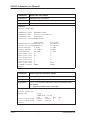
Command
Show M1112 information
Description
Displays M1112 hardware and software information.
Syntax
show status [session | performance]
Arguments
Optional arguments session and performance.
session shows information of the active configuration
sessions. If login-id is used, it is shown on the screen.
performance shows error counters.
Example
M1112> show status
product-id
serial-num
cpu-type
flash-type
sdram-type
phys-address-lan
phys-address-wan
short-desc
long-desc
boot-version
appl-version
log-severity
start-uptime
M1112>
5-34
T66285.01
61000206829
XPC850SR / B
2 M
8 M
00:40:43:02:36:80
00:40:43:02:36:81
M1112
NOKIA M1112
ADSL over ISDN router
B-R0.0.8
Gx1x2200.R00
HIGH
00/00:37:26
E Copyright Nokia Networks Oy
C33907001SE_00
Managing M1112
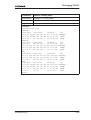
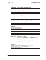
Command
Show running configuration
Description
Displays currently active configuration. If you have
made changes in the configuration and you want them
to be active after restart, save the current configuration
to startup.cfg file using save config command.
Syntax
show config running
Arguments
None
Example
M1112> show config running
system
hostname M1112
eth
ip address 192.168.172.148
255.255.255.128
vcc1
pvc 0 155 tunneled-ppp-vc
bridging
vcc2
pvc 0 156 ppp-vc
ip address 0.0.0.0 0.0.0.0
ppp authentication chap
ppp username nokia
ppp password mypassword
vbridge
mngtvcc
common
M1112>
C33907001SE_00
E Copyright Nokia Networks Oy
5-35
M1112 Administrator Manual
Command
Show startup configuration
Description
Displays the startup configuration of your M1112. This
is the configuration saved in the startup.cfg file. Startup.cfg file is activated when M1112 is switched on. If
the startup.cfg file is missing, the default configuration
is used.
Syntax
show config startup
Arguments
None
Example
M1112> show config startup
system
hostname M1112
eth
ip address 192.168.172.148
255.255.255.128
vcc1
pvc 0 155 tunneled-ppp-vc
bridging
vbridge
mngtvcc
common
M1112>
Command
Show default configuration
Description
Displays the default configuration of M1112. M1112
uses this configuration if the startup.cfg file is missing.
Syntax
show config default
Arguments
None
Example
M1112> show config default
system
hostname Mxx
eth
bridging
vcc1
pvc 0 100 eth-llc
bridging
vbridge
mngtvcc
common
M1112>
5-36
E Copyright Nokia Networks Oy
C33907001SE_00
Managing M1112
Command
Show configuration file
Description
Displays the local configuration file
Syntax
show config file <filename>
Arguments
filename is the name of the local configuration file.
Example
M1112> show config file startup.cfg
M1112>
Command
Show debug status
Description
Displays the status (ON/OFF) of the debug functions.
Syntax
show debug
Arguments
None.
Example
M1112> show debug
log
OFF
eth
OFF
atm-aal5
OFF
pptp
OFF
ip-host
OFF
ip-icmp
OFF
napt-entry
OFF
napt-h323
OFF
dns
OFF
M1112>
dsl
atm-aal0
ppp
arp
ip-forward
napt-map
napt-internal
dhcp
OFF
OFF
OFF
OFF
OFF
OFF
OFF
OFF
Command
Ping
Description
Send an ICMP echo request to an IP address to test
the IP function.
Syntax
ping <ip-address>
Arguments
ip-address is the IP address of the ping destination
in dotted decimal format.
Example
M1112> ping 198.168.172.23
Reply from 198.168.172.23: bytes 32 time <10ms
TTL=128
M1112>
C33907001SE_00
E Copyright Nokia Networks Oy
5-37
M1112 Administrator Manual
Command
ATMping
Description
Sends five OAM F5 loopback cells to the specified VPI/
VCI destination with a 5 second total timeout interval.
You can use ATMping to test the ATM connection.
Syntax
atmping <vpi> <vci> <range>
Arguments
vpi is the Virtual Path Identifier and vci is the Virtual
Channel Identifier of the ATM channel you want to test.
vpi values are integers (0...255).
vci values are integers (0...65535)
range values are segment and end-to-end depending whether you want to test the first segment of the
ATM connection or the end-to-end connection.
Example
M1112> atm ping 0 23 segment
reply asserted roundtrip time = 4.20 ms
M1112>
The debug commands are used to solve difficult problem situations.
The debugging can be switched off with the following command.
Other debugging commands are not handled in this manual.
Command
Switch off debug
Description
Switches all debug operations off. To quit debugging,
write no debug all on the screen regardless of what is
being printed on the screen.
Syntax
no debug all
Arguments
no switches debugging off.
Example
M1112> no debug all
M1112>
5-38
E Copyright Nokia Networks Oy
C33907001SE_00
Managing M1112
Command
Show contents of file directory
Description
Displays the contents of M1112 file directory.
Syntax
dir
Arguments
None
Example
M1112> dir
filename
size
startup.cfg 195
image.exe
375007
nr-of-files 2
avail-media 1454306 bytes
M1112>
appl-version
Gx1x2200.R00
Command
Copy file
Description
Copies files within M1112 or over a TFTP (Trivial File
Transfer Protocol) connection. With this command you
can, for example, download configuration files.
Syntax
copy [file:/] <src-filename> [file:/] <dst-filename>
copy [file:/] <src-filename> tftp:/<ip-address>/<../dstfilename>
copy tftp:/<ip-address>/<../src-filename> [file:/] <dstfilename>
Arguments
src-filename is the name of the file you want to
copy.
dst-filename is its destination filename.
ip-address is the IP address of the TFTP server.
Example
M1112>copy tftp:/191.111.111.1/file.txt file.new
M1112>
C33907001SE_00
E Copyright Nokia Networks Oy
5-39
M1112 Administrator Manual
Command
Rename file
Description
Renames a file
Syntax
rename <old-filename> <new-filename>
Arguments
old-filename is the name of the file you want to rename.
new-filename is the new filename.
Example
M1112> rename newconfig oldconfig
M1112>
Command
Delete file
Description
Deletes a file
Syntax
delete <del-filename>
Arguments
del-filename is the name of the file you want to delete.
Example
M1112> delete oldfile
M1112>
Command
Download new firmware
Description
Downloads a new firmware from a TFTP server. Remember to restart M1112 after downloading to activate
the new firmware.
Syntax
install tftp:/<ip-address>/<../src-filename>
Arguments
ip-address is the IP address of the TFTP server.
src-filename is the name of the file which contains
the new software.
Example
M1112> install tftp:/10.98.20.6/appl-A0.4.2
blocks received
transfer status SUCCESSFUL
M1112> restart
...
5-40
E Copyright Nokia Networks Oy
C33907001SE_00
Managing M1112
Command
Execute a command batch
Description
Executes a custom command batch.
Syntax
script <batch-filename>
Arguments
batch-filename is the name of the file in which you
want to execute.
Example
M1112>script swap.bat
M1112>
Command
Save log to file
Description
Saves log to a file.
Syntax
save log file<log-filename>
Arguments
log-filename is the name of the file in which you
want to save the log.
Example
M1112>save log file log.txt
M1112>
Command
Save log to a default file
Description
Saves log with a default file name (default.log).
Syntax
save log default
Arguments
None
Example
M1112>save log default
M1112>
C33907001SE_00
E Copyright Nokia Networks Oy
5-41
M1112 Administrator Manual
Command
Save configuration to file
Description
Saves the configuration to a file.
Syntax
save config {file<filename> | startup | user}
Arguments
filename is the name of the file in which you want to
save the configuration.
startup-config argument saves the configuration
into a startup.cfg file.
user saves the user configuration.
Example
M1112>save config startup-config
M1112>
Command
Restore configuration
Description
Restores the default or user configuration. You must
have the admin privileges to issue this command. Restart your M1112 after you have issued this command.
Syntax
restore config {default | user}
Arguments
default argument restores the default configuration of
M1112.
user argument restores the user configuration. The
user configuration can be made with admin rights only.
Example
M1112>restore config default
M1112>
Command
Clear counters
Description
Clears the statistics counters.
Syntax
clear {log | eth | atm | bridge | ppp | ip}
Arguments
log argument rewinds the diagnostic log to the beginning of the log file.
eth argument clears the Ethernet statistics counters.
atm argument clears the ATM statistics counters.
bridge argument clears the bridging counters.
ppp argument clears the PPP counters.
ip argument clears the IP statistics counters.
Example
M1112> clear log
M1112>
5-42
E Copyright Nokia Networks Oy
C33907001SE_00
Managing M1112
Command
Reset subsystem
Description
Resets subsystems.
Syntax
reset {log | dsl | ppp [vcc-id] | arp | bridge | napt}
Arguments
log resets the diagnostic log subsystem.
dsl resets the DSL subsystem. The DSL connection
will be re-established.
ppp resets the whole PPP subsystem. The PPP connection will be re-establihed. If you provide a VCC
number (vcc-id), only that connection will be reseted.
arp clears the ARP table.
bridge clears the bridge table.
napt resets the NAPT subsystem.
Example
M1112> reset bridge
M1112>
Command
Logout
Description
Logs out from the command line interface.
Syntax
logout
Arguments
None
Example
M1112>logout
Command
Fast restart M1112
Description
Restarts M1112 software.
Syntax
reload
Arguments
None
Example
M1112>reload
in progress...
C33907001SE_00
E Copyright Nokia Networks Oy
5-43
M1112 Administrator Manual
Command
Restart M1112
Description
Restarts M1112. This command is equivalent to switching the power first off and then on.
Syntax
restart
Arguments
None
Example
M1112> restart
in progress...
Command
Switch to configuration mode
Description
Switches to the configuration mode. The configuration
mode lets you change the configuration of M1112.
Syntax
configure
Arguments
None
Example
M1112>configure
M1112(conf)#
5.4.2
Configuration mode commands
Command
Return to root level
Description
Returns you to the root level from a higher configuration level.
Syntax
top
Arguments
None.
Example
M1112(conf-system)#top
M1112(conf)#
5-44
E Copyright Nokia Networks Oy
C33907001SE_00
Managing M1112
Root level commands
Command
Show current running configuration
Description
Displays currently running configuration.
Syntax
show
Arguments
None
Example
M1112(conf)# show
system
hostname M1112
eth
bridging
vcc1
pvc 0 100 eth-llc
bridging
vcc2
vcc3
vcc4
vcc5
vcc6
vcc7
vcc8
vbridge
mngtvcc
common
M1112>
show command given on different configuration levels displays the
current configuration of that particular configuration level.
Use the following commands to enter different configuration levels:
system
password
eth
vcc1 ... vcc8
vbridge
mngtvcc
common
C33907001SE_00
E Copyright Nokia Networks Oy
5-45
M1112 Administrator Manual
System level commands
Command
Assign hostname
Description
Assigns a hostname to M1112.
Syntax
hostname <name-string>
Arguments
name-string is an ASCII string of maximum of 32
characters.
Example
M1112(conf-system)#hostname nokia
nokia(conf-system)#
Command
Set configuration session timeout
Description
Sets a timeout for a management session.
Syntax
timeout <value>
Arguments
value is a time from 1 to 255 minutes.
Example
M1112(conf-system)#timeout 10
nokia(conf-system)#
5-46
E Copyright Nokia Networks Oy
C33907001SE_00
Managing M1112
Password level command
Command
Assign new password
Description
Switches password on/off and sets a new password for
different user levels. Note, that you must assign admin
password before you can assign other passwords.
When removing passwords, admin password must be
removed last.
Syntax
[no] {user | bridge-user | router-user | pptp-user | naptuser | admin} <passwd-string>
Arguments
no switches off user password.
user argument sets the user privilege level password.
User password gives no access to the configuration
mode. Also, firmware download is not allowed on the
user privilege level.
bridge-user sets the bridge-user privilege level
password. Bridge user can set static routes and enable
VBRIDGE IP address.
router-user sets the router-user privilege level password. Router user can change log levels and hostname.
pptp-user sets the PPTP-user privilege level password. PPTP user can change VCCx description, DHCP,
DNS and LAN/VBRIDGE configurations.
napt-user set the NAPT-user privilege level password. NAPT user can change VCCx description, LAN/
VBRIDGE, NAPT servers (pinholes), PPP username/
password/mode/autostop, DHCP, DNS configurations,
and set static routes.
admin sets the administrator privilege level password.
Administrator can change all configuration parameters.
Only the administrator is allowed to use file handling
commands (copy, rename, etc.).
passwd-string is the new password.
Example
M1112> admin nokia
M1112
C33907001SE_00
E Copyright Nokia Networks Oy
5-47
M1112 Administrator Manual
Ethernet level commands
Command
Switch on/off bridging
Description
Switches on/off bridging.
Syntax
[no] bridging
Arguments
no switches bridging off.
Example
M1112(conf-eth)#bridging
M1112(conf-eth)#
Command
Switch on/off IP function in Ethernet interface
Description
Switches on/off IP function in the Ethernet interface.
Syntax
[no] ip address <ip-address> <ip-mask>
Arguments
no switches IP function off.
ip-address is the IP address you want to assign to
the Ethernet interface.
ip-mask is the subnet mask.
Example
M1112(conf-eth)#ip address 192.168.132.11
255.255.255.0
M1112(conf-eth)#
Command
Switch on/off RIP send function in Ethernet interface
Description
Switches on/off RIP send function. When enabled
M1112 sends Routing Information Protocol messages
to other routers.
Syntax
[no] ip rip-send {rip-send-mode}
Arguments
no switches rip-send function off.
v1 send-mode selects RIP version 1.
v2 send-mode selects RIP version 2.
compatible-v1 send-mode selects the sending of
RIPv2 packets using broadcast.
Example
M1112(conf-eth)#ip rip-send v1
M1112(conf-eth)#
5-48
E Copyright Nokia Networks Oy
C33907001SE_00
Managing M1112
Command
Switch on/off RIP receive function in Ethernet interface
Description
Switches on/off RIP send function. When enabled
M1112 receives Routing Information Protocol messages from other routers.
Syntax
[no] ip rip-receive {rip-receive-mode}
Arguments
no switches RIP receive function off.
v1 receive-mode selects RIP version 1.
v2 receive-mode selects RIP version 2.
both-v1v2 receive-mode selects both RIP version 1
and version 2.
Example
M1112(conf-eth)#ip rip-receive v1
M1112(conf-eth)#
Command
Disable/enable management through the Ethernet
interface
Description
Enables/disables the management of M1112 through
the Ethernet interface.
Syntax
[no] ip admin-disabled
Arguments
no enables management through the Ethernet interface.
Example
M1112(conf-eth)#ip admin-disabled
M1112(conf-eth)#
C33907001SE_00
E Copyright Nokia Networks Oy
5-49
M1112 Administrator Manual
VCC (ATM channel) commands
Command
Activate ATM channel
Description
Activates an ATM channel and sets the encapsulation
for that channel.
Syntax
[no] pvc <vpi> <vci> <encap>
Arguments
no deactivates the ATM channel.
vpi is the Virtual Path Identifier of the ATM channel.
Possible values are 0...255.
vci is the Virtual Channel Identifier of the ATM channel. Possible values are 0...65535.
encap is the encapsulation of the ATM channel. The
encapsulations are auto-llc, eth-llc, ip-llc,
ppp-vc, and tunneled-ppp-vc. auto-llc encapsulates the routed packets in ip-llc and the bridged
packets in eth-llc.
Example
M1112(conf-vccx)#pvc 0 100 ip-llc
M1112(conf-vccx)#
Command
Switch on/off bridging
Description
Switches bridging on/off on the specified ATM channel.
Syntax
[no] bridging
Arguments
no switches off bridging.
Example
M1112(conf-vccx)#bridging
M1112(conf-vccx)#
5-50
E Copyright Nokia Networks Oy
C33907001SE_00
Managing M1112
Command
Switch on/off PPP authentication
Description
Switches PPP authentication on/off on the specified
ATM channel.
Syntax
[no] ppp authentication {mode}
Arguments
no switches off PPP authentication.
chap mode selects Challenge Handshake Authentication Protocol.
pap mode selects Password Authentication Protocol.
both-chap-pap mode selects both authentication
protocols.
Example
M1112(conf-vccx)#ppp authentication chap
M1112(conf-vccx)#
Command
Set PPP username
Description
Sets the username used in PPP authentication.
Syntax
[no] ppp username <name-string>
Arguments
no deletes PPP username.
name-string is your PPP username. The maximum
length of the username is 15 characters.
Example
M1112(conf-vccx)#ppp username ut32aj
M1112(conf-vccx)#
Command
Set PPP password
Description
Sets the password used in PPP authentication.
Syntax
[no] ppp password <passwd-string>
Arguments
no deletes PPP password.
passwd-string is the PPP password. The password
must be 4...15 characters long.
Example
M1112(conf-vccx)#ppp password jfddslfj
M1112(conf-vccx)#
C33907001SE_00
E Copyright Nokia Networks Oy
5-51
M1112 Administrator Manual
Command
Stop PPP negotiation when authentication failure
occurs
Description
When enabled, the athentication failure causes the
PPP negotiation to stop. The command reset ppp
vccx is required to restart the PPP negotiation.
Syntax
[no] ppp autostop
Arguments
no disables PPP autostop.
Example
M1112(conf-vccx)#ppp autostop
M1112(conf-vccx)#
Command
Switch on/off IP function on ATM channel
Description
Switches on/off IP function on the ATM channel.
Syntax
[no] ip address <ip-address> <ip-mask>
Arguments
no switches IP function off.
ip-address is the IP address you want to assign to
the ATM channel. IP address 0.0.0.0 with subnet mask
0.0.0.0 can be used with ppp-vc encapsulation if the
dynamic IP address negotiation is required.
ip-mask is the subnet mask.
Example
M1112(conf-vccx)#ip address 192.168.132.13
255.255.255.0
M1112(conf-vccx)#
Command
Switch on/off RIP send function on ATM channel
Description
Switches on/off RIP send function. When enabled,
M1112 sends Routing Information Protocol messages
to other routers.
Syntax
[no] ip rip-send {rip-send-mode}
Arguments
no switches rip-send function off.
v1 send-mode selects RIP version 1.
v2 send-mode selects RIP version 2.
compatible-v1 send-mode selects the sending of
RIPv2 packets using broadcast.
Example
M1112(conf-vccx)#ip rip-send v1
M1112(conf-vccx)#
5-52
E Copyright Nokia Networks Oy
C33907001SE_00
Managing M1112
Command
Switch on/off RIP receive function on ATM channel
Description
Switches on/off RIP receive function. When enabled,
M1112 receives Routing Information Protocol messages from other routers.
Syntax
[no] ip rip-receive {rip-receive-mode}
Arguments
no switches RIP receive function off.
v1 receive-mode selects RIP version 1.
v2 receive-mode selects RIP version 2.
both-v1v2 receive-mode selects both RIP version 1
and version 2.
Example
M1112(conf-vccx)#ip rip-receive v1
M1112(conf-vccx)#
Command
Enable Network Address Port Translation
Description
Enables Network Address Port Translation.
Syntax
[no] ip napt
Arguments
no switches NAPT function off.
Example
M1112(conf-vccx)#ip napt
M1112(conf-vccx)#
C33907001SE_00
E Copyright Nokia Networks Oy
5-53
M1112 Administrator Manual
Command
Set server support entry
Description
Sets a NAPT server support entry.
Syntax
[no] ip server-napt <pool-string><hidden-address>
<hidden-pool-base> <public-pool-base> <pool-size>
<protocol-id>
Arguments
no deletes pinhole entry.
pool-string identifies the server entry.
hidden-address is the address of the local server for
which the pinhole is made.
hidden-pool-base is the start of the local port
range.
public-pool-base is the start of the external port
range.
pool-size is the size of the port range.
protocol-id is the protocol allowed through the pinhole. Available protocols are: UDP, TCP, PPTP-GRE,
and ESP-IPSEC
Example:
When hidden-pool-base is 80, public-poolbase is 80 and pool-size is 1, traffic coming to external port (WAN port) 80 will be mapped to internal port
80.
Example
M1112(conf-vccx)#ip server-napt web_server
192.168.1.100 80 80 1 tcp
M1112(conf-vccx)#
Command
Disable/enable management through the ATM channel
Description
Enables/disables the management of M1112 through
the ATM channel.
Syntax
[no] ip admin-disabled
Arguments
no enables management through the ATM channel.
Example
M1112(conf-vccx)#ip admin-disabled
M1112(conf-vccx)#
5-54
E Copyright Nokia Networks Oy
C33907001SE_00
Managing M1112
Vbridge commands
Command
Switch on/off IP function in vbridge
Description
Switches on/off IP function.
Syntax
[no] ip address <ip-address> <ip-mask>
Arguments
no switches off IP function.
ip-address is the IP address of the Vbridge in dotted
decimal notation.
ip-mask is the subnet mask in dotted decimal notation.
Example
M1112(conf-vbridge)#ip address nnn.nnn.nnn.nnn
255.255.255.0
M1112(conf-vbridge)#
Command
Switch on/off RIP receive function in vbridge
Description
Switches on/off RIP receive function. When enabled,
M1112 receives Routing Information Protocol messages from other routers.
Syntax
[no] ip rip-receive {rip-receive-mode}
Arguments
no switches RIP receive function off.
v1 receive-mode selects RIP version 1.
v2 receive-mode selects RIP version 2.
both-v1v2 receive-mode selects both RIP version 1
and version 2.
Example
M1112(conf-vbridge)#ip rip-receive v1
M1112(conf-vbridge)#
Command
Disable/enable management through the vbridge
Description
Enables/disables the management of M1112 through
the vbridge.
Syntax
[no] ip admin-disabled
Arguments
no enables management through the ATM channel.
Example
M1112(conf-vbridge)#ip admin-disabled
M1112(conf-vbridge)#
C33907001SE_00
E Copyright Nokia Networks Oy
5-55
M1112 Administrator Manual
Command
Switch on/off VCC-to-VCC bridging
Description
Switches on/off bridging between ATM channels.
Syntax
[no] interwan-bridging
Arguments
no switches off bridging between ATM channels.
Example
M1112(conf-vbridge)#interwan-bridging
M1112(conf-vbridge)#
Dedicated management channel commands
Command
Activate dedicated management channel
Description
Activates a dedicated management channel and sets
the encapsulation for that channel.
Syntax
[no] pvc <vpi> <vci> <encap>
Arguments
no deactivates the ATM channel.
vpi is the Virtual Path Identifier of the ATM channel.
Possible values are 0...255.
vci is the Virtual Channel Identifier of the ATM channel. Possible values are 0...65535.
encap is the encapsulation of the ATM channel. Encapsulations are ppp-vc, eth-llc, and ip-llc.
Example
M1112(conf-mngtvcc)#pvc 0 100 eth-llc
M1112(conf-mngtvcc)#
5-56
E Copyright Nokia Networks Oy
C33907001SE_00
Managing M1112
Command
Switch on/off IP function on dedicated management channel
Description
Switches on/off IP function.
Syntax
[no] ip address <ip-address> <ip-mask>
Arguments
no switches off IP function.
ip-address is the IP address of the Vbridge in dotted
decimal notation. IP address 0.0.0.0 with subnet mask
0.0.0.0 can be used with ppp-vc encapsulation if the
dynamic IP address negotiation is required.
ip-mask is the subnet mask in dotted decimal notation.
Example
M1112(conf-mngtvcc)#ip address nnn.nnn.nnn.nnn
255.255.255.0
M1112(conf-mngtvcc)#
Command
Switch on/off RIP receive function on dedicated
management channel
Description
Switches on/off RIP receive function.
Syntax
[no] ip rip-receive {rip-receive-mode}
Arguments
no switches rip-send function off.
v1 receive-mode selects RIP version 1.
v2 receive-mode selects RIP version 2.
both-v1v2 receive-mode selects both RIP version 1
and version 2.
Example
M1112(conf-mngtvcc)#ip rip-receive v1
M1112(conf-mngtvcc)#
Common commands
Command
Set PPP packet size
Description
Sets the maximum size of the received PPP packets.
Syntax
[de] ppp mru <size>
Arguments
size is the size of a PPP packet. Default size is 1500.
Example
M1112(conf-common)#ppp mru 1000
M1112(conf-common)#
C33907001SE_00
E Copyright Nokia Networks Oy
5-57
M1112 Administrator Manual
Command
Set PPP restart time parameter
Description
Defines how long M1112 waits for the configure-request
packet.
Syntax
[de] ppp restart <time>
Arguments
time in seconds.
Example
M1112(conf-common)#ppp restart 5
M1112(conf-common)#
Command
Set max-config parameter value
Description
Defines how many times the configure-request packet
will be sent.
Syntax
[de] ppp max-config <pkt-count>
Arguments
pkt-count is the number of configure request
packets, values 1...30.
Example
M1112(conf-common)#ppp max-config 10
M1112(conf-common)#
Command
Set max-terminate parameter value
Description
Defines how many terminate-request packets will be
sent before M1112 decides that the connection is down.
Syntax
[de] ppp max-terminate <pkt-count>
Arguments
pkt-count is the number of configure request
packets, values 1...30.
Example
M1112(conf-common)#ppp max–terminate 10
M1112(conf-common)#
5-58
E Copyright Nokia Networks Oy
C33907001SE_00
Managing M1112
Command
Set max-failure parameter value
Description
Defines how many times PPP options will be offered
before the negotiation fails.
Syntax
[de] ppp max-failure <pkt-count>
Arguments
pkt-count is the number of packets, values 1...30.
Example
M1112(conf-common)#ppp max-failure 10
M1112(conf-common)#
Command
Switch on/off IP cache
Description
Switches IP cache on/off. Enabled IP cache increases
the speed of the IP packet forwarding.
Syntax
[no] ip cache
Arguments
no switches IP cache off.
Example
M1112(conf-common)#
M1112(conf-common)#
Command
Add/delete IP route
Description
Adds/deletes an IP route
Syntax
[no] ip route <dest-net> <net-mask> <gateway> <if>
Arguments
no deletes an IP route.
dest-net is the IP address of the destination in the
dotted decimal notation.
net-mask is the subnet mask of the destination in
dotted decimal notation.
gateway is the default gateway for the route.
if is the interface through which the destination can be
reached, vbridge or mngtvcc.
Example
M1112(conf-common)#ip route 131.112.11.1
255.255.255.0 131.2.111.2 mngtvcc
M1112(conf-common)#
C33907001SE_00
E Copyright Nokia Networks Oy
5-59
M1112 Administrator Manual
Command
Define and activate host acces list
Description
You can define up to four IP addresses from which MW
1122 can be accessed using telnet or http. f you define
one or more addresses, M1112 can be accessed from
the specified addresses only.
Syntax
[no] ip host-acl <ip-address> <ip-mask>
Arguments
no switches host access list off.
ip-address is the allowed host address and ipmask is its subnet mask.
Example
M1112(conf-common)#ip host-acl 192.168.1.17
255.255.255.0
M1112(conf-common)#
Command
Switch on/off dynamic host configuration protocol
Description
Switches on/off dynamic host configuration protocol.
Syntax
[no] dhcp mode <service>
Arguments
no switches off DHCP.
service parameter value is server when you want to
use M1112 as a DHCP server.
Example
M1112(conf-common)#dhcp mode server
M1112(conf-common)#
5-60
E Copyright Nokia Networks Oy
C33907001SE_00
Managing M1112
Command
Set DHCP address range
Description
You can define to DHCP address ranges with this command. The default pool is the IP address of the interface with a subnet mask 255.255.255.0.
If you don’t define an address range, up to two ranges
will be defined automatically for ETH/VBRIDGE interfaces, in this order, if the interface has an IP address.
Syntax
[no] dhcp address <scope> <pool-base> <pool-mask>
<pool-size>
Arguments
no switches of address pool.
scope defines the pool. Values are 1 and 2.
pool-base is the first IP address in the pool in dotted
decimal format.
pool-mask is the subnet mask of the pool addresses.
pool-size is the size of the address pool, 0...254.
Example
M1112(conf-common)#dhcp address 1 168.190.1.1
255.255.255.0 100
M1112(conf-common)#
Command
Set DNS address for DHCP clients
Description
Defines a DNS address for the DHCP clients.
Syntax
[de | no] dhcp dns <scope> <class> <dns-server>
Arguments
scope defines the DHCP pool (1 or 2).
class defines whether the server is a primary or a
secondary server.
dns-server is the IP address of the DNS server.
Example
M1112(conf-common)#dhcp dns 1 primary 190.168.2.1
M1112(conf-common)#
C33907001SE_00
E Copyright Nokia Networks Oy
5-61
M1112 Administrator Manual
Command
Set DHCP server lease time
Description
Defines the time how often the PC has to renew its
DHCP lease.
Syntax
[de | no] dhcp lease-time <scope> <time-count>
Arguments
scope defines the DHCP pool (1 or 2).
time-count is the renewal interval in minutes,
1...65535.
Example
M1112(conf-common)#dhcp lease-time 1 360
M1112(conf-common)#
Command
Set DHCP pool domain name
Description
Set the domain name for the DHCP pool. The domain
name is used to show the client in which network the
client is in.
Syntax
[no] dhcp domain-name <scope> <name-string>
Arguments
scope defines the DHCP pool (1 or 2).
name-string set the domain name.
Example
M1112(conf-common)#dhcp domain-name 1 nokia
M1112(conf-common)#
Command
Set Domain name server address
Description
Defines the address of the domain name server used
by M1112.
Syntax
[no] dns <class> <dns-server>
Arguments
no deletes domain name server address.
class defines whether the server is a primary or a
secondary name server.
dns-server is the IP address of the DNS server.
Example
M1112(conf-common)#dns primary 190.168.12.1
M1112(conf-common)#
5-62
E Copyright Nokia Networks Oy
C33907001SE_00
Managing M1112
Command
Switch on/off weighted fair queueing
Description
Switches on/off weighted fair queueing.
Syntax
[no] misc global-wfq
Arguments
no switches off weighted fair queueing.
Example
M1112(conf-common)#misc global-wfq
M1112(conf-common)#
C33907001SE_00
E Copyright Nokia Networks Oy
5-63
M1112 Administrator Manual
5-64
E Copyright Nokia Networks Oy
C33907001SE_00
Technical specifications
Appendix A
Technical specifications
Features
ADSL
Physical layer
ETSI TS 101 388 compatible
ADSL line connector
RJ-11
ATM over ADSL
ATM connections
PVC, up to 8 virtual circuits
Service categories
UBR
Encapsulations
RFC2684 ETH-LLC, RFC2684 IP-LLC,
RFC2364 PPP-VC, RFC2364 TUNNELEDPPP-VC
Ethernet interface
Ethernet
10Base-T, half duplex
Encapsulation
DIXv2 (transmit), IEEE 802.3 and DIXv2 (receive)
Ethernet connectors
RJ-45
Routing
Routing protocols
RIPv1, RIPv2, and static routes
Other
NAPT, IGMP proxy, DHCP server, DNS relay,
PPTP local tunneling
Class of Service
Weighted fair queueing
Bridging
C33907001SE_00
E Copyright Nokia Networks Oy
A-1
M1112 Administrator Manual
Features
Bridging
Self-learning bridge, bridges between all interfaces. Possibility to disable bridging between
WAN interfaces.
MAC table
1024 entries
Class of Service
Weighted fair queueing
Command line interface (CLI) for local management
Physical layer
Electrically RS-232, TxD, RxD and GND signals
Data format
Asynchronous, 8+no parity
Bit rate
9600 bps
Flow control
None
CLI connector
RJ-45
Dedicated ATM management channel
Service categories
UBR
Encapsulations
RFC2684 ETH-LLC, RFC2684 IP-LLC,
RFC2364 PPP-VC
IP addressing
Statically configured
Through IPCP when PPP over ATM is used
Routing
Static routes
RIPv1, RIPv2
Management protocols
Telnet/TCP/IP for command line interface,
TFTP/UDP/IP for software and configuration
download, HTTP/web server
Management through payload
Management protocols
Telnet/TCP/IP for command line interface,
TFTP/UDP/IP for software and configuration
download, HTTP/web server
Indicator lights
A-2
DSL
ADSL line status
ETH-1, ETH-2,
ETH-3, ETH-4
Ethernet activity and status
COL
Ethernet collision
STA
M1112 startup error
PWR
Power on
E Copyright Nokia Networks Oy
C33907001SE_00
Technical specifications
A.1 Mechanical construction and power supply
M1112 is a stand-alone device which can also be wall-mounted.
Mechanical construction
Width
225 mm
Height
65 mm
Depth
230 mm
Weight
1 kg
Table A-1
Mechanical construction
M1112 has an in-built power supply. The characteristics of the mains
connection are presented in Table A-2.
Mains connection
Voltage
100 ... 240 VAC
Frequency
45 ... 65 Hz
Power consumption
8W
Table A-2
Mains connection
A.2 Ambient conditions, EMC and safety
Ambient conditions
Operating temperature range 5 to 45°C
Humidity
10% to 90%, non-condensing
EMC
M1112 complies with the following specifications provided that the
device is connected to an earthed socket outlet:
Emission
EN55022: 1998 class B
Immunity
EN55024: 1998
EMC
EN300386-2: 1997
C33907001SE_00
E Copyright Nokia Networks Oy
A-3
M1112 Administrator Manual
A-4
Overvoltage
ITU-T K.21
Safety
Safety
EN60950
E Copyright Nokia Networks Oy
C33907001SE_00
Glossary
Glossary
Abbreviations
ADSL
Asymmetric digital subscriber line
ATM
Asynchronous transfer mode
CLI
Command line interface
COL
Collision
DMT
Discrete multitone
DSL
Digital subscriber line
DSLAM
Digital Subscriber Line Access Multiplexer
EMC
Electromagnetic compatibility
ETH
Ethernet
IP
Internet protocol
ISDN
Intergrated services digital network
ISP
Internet service provider
L2TP
Layer 2 tunneling protocol
LAN
Local area network
LLC
Logical link control
MAC
Media access control
PC
Personal computer
POTS
Plain old telephone system
PPP
Point-to-point protocol
C33907001SE_00
E Copyright Nokia Networks Oy
Glossary-1
M1112 Administrator Manual
PPTP
Point-to-point tunneling protocol
PWR
Power
RAN
Remote access node
RFC
Request for comments
STA
Status
TCP
Transmission control protocol
UBR
Unspecified bit rate
VCC
Virtual channel connection
VCI
Virtual channel identifier
VPI
Virtual path identifier
WWW
World Wide Web
Terms
10Base-T
10 Mbit/s Ethernet specification using two pairs of twisted cabling.
10Base-T is a part of the IEEE 802.3 specification.
ATM access network
An access network where traffic from the subscribers is multiplexed
and forwarded using ATM technology.
bridge
A device that connects two or more physical networks and forwards
packets between them. Bridges can usually be made to filter packets,
that is, to forward only certain traffic.
command line interface
Character-based man-machine interface where a command line ending with <CR> character is used to configure a device. The device interprets the command and returns a character-based response.
Glossary-2
E Copyright Nokia Networks Oy
C33907001SE_00
Glossary
Digital Subscriber Line Access Multiplexer
A network element which multiplexes the traffic coming from the
high-speed subscriber lines and forwards this traffic to the ATM network.
encapsulation
Wrapping of data in a protocol header.
Ethernet
LAN specification IEEE 802.3.
host
Computer system on a network.
Integrated services digital network
Integrated services network that provides digital connections between
user-network interfaces. ISDN provides or supports a range of different telecommunications services, for example a variety of telephony
and data services.
IP network
Data communications network based on the Internet Protocol.
ISDN filter
A device used for separating the ISDN signal from ADSL data signals
in the digital subscriber line.
MAC address
Ethernet address.
C33907001SE_00
E Copyright Nokia Networks Oy
Glossary-3
M1112 Administrator Manual
multiplexer
A device where several logical connections are combined into one
physical connection.
remote access node
RAN accepts a high concentration of data traffic from many DSLAMs.
It grooms the traffic to reduce the heavy processing load for backbone
routers which can limit the scalability of high-speed networks. RAN
receives cell- or frame-based end user traffic from the DSLAM and
sends the aggregated IP traffic to ISP backbone routers.
serial console connection
Serial connection (CLI) on the back panel of M5122. It is used for
configuring M5122 locally.
telecommuter
A person who works at home with data communications to the central
office.
virtual channel
A communications channel which provides for the sequential unidirectional transport of ATM cells.
virtual channel connection
A concatenation of virtual channel links that extends between the
points where the ATM service users access the ATM layer.
virtual path
A unidirectional logical association of virtual channels.
Glossary-4
E Copyright Nokia Networks Oy
C33907001SE_00
Glossary
web browser
A software that is used to browse the World Wide Web.
C33907001SE_00
E Copyright Nokia Networks Oy
Glossary-5
M1112 Administrator Manual
Glossary-6
E Copyright Nokia Networks Oy
C33907001SE_00