1
Nokia M/MW Gateways
M1112, M1122, MW1112,
MW1122, MW1324, MW1352
User Manual
C34300001SE_00
DN01154358
Issue 1-0 en
© Nokia Networks Oy
Nokia Proprietary and Confidential
1 (40)
Nokia M/MW Gateways M1112, M1122, MW1112, MW1122, MW1324, MW1352
The information in this document is subject to change without notice and describes only the
product defined in the introduction of this documentation. This document is intended for the
use of Nokia Networks' customers only for the purposes of the agreement under which the
document is submitted, and no part of it may be reproduced or transmitted in any form or
means without the prior written permission of Nokia Networks. The document has been
prepared to be used by professional and properly trained personnel, and the customer
assumes full responsibility when using it. Nokia Networks welcomes customer comments as
part of the process of continuous development and improvement of the documentation.
The information or statements given in this document concerning the suitability, capacity, or
performance of the mentioned hardware or software products cannot be considered binding
but shall be defined in the agreement made between Nokia Networks and the customer.
However, Nokia Networks has made all reasonable efforts to ensure that the instructions
contained in the document are adequate and free of material errors and omissions. Nokia
Networks will, if necessary, explain issues which may not be covered by the document.
Nokia Networks' liability for any errors in the document is limited to the documentary correction
of errors. Nokia Networks WILL NOT BE RESPONSIBLE IN ANY EVENT FOR ERRORS IN
THIS DOCUMENT OR FOR ANY DAMAGES, INCIDENTAL OR CONSEQUENTIAL
(INCLUDING MONETARY LOSSES), that might arise from the use of this document or the
information in it.
This document and the product it describes are considered protected by copyright according to
the applicable laws.
NOKIA logo is a registered trademark of Nokia Corporation.
Other product names mentioned in this document may be trademarks of their respective
companies, and they are mentioned for identification purposes only.
Copyright © Nokia Networks Oy 2001. All rights reserved.
2 (40)
© Nokia Networks Oy
Nokia Proprietary and Confidential
DN01154358
Issue 1-0 en
Contents
Contents 3
1
1.1
1.2
About this manual 5
Purpose of this manual 5
Models covered in this manual 5
2
Introduction to Nokia M and MW Gateways 7
3
3.1
3.2
3.3
Preparations 9
What you need to access the Internet 9
Check the contents of the package 9
Get acquainted with your gateway's indicator lights and connectors 10
4
4.1
4.2
4.3
4.4
Physical installation 13
Placing the gateway on a table or desk 13
Installing the gateway on a wall 13
Connecting the data cables (and WLAN cards) 16
Installing an external WLAN antenna (MW series only) 17
5
5.1
5.2
5.3
Configuring your PC(s) and gateway for use 19
Finding out the gateway's IP address or name 19
Opening a connection to the gateway with a browser 20
Configuring your computer settings 22
6
6.1
6.2
6.3
Basic WLAN configurations (MW models only) 23
Changing the wireless LAN settings 23
Enabling admission control 24
Enabling wireless encryption 26
7
Troubleshooting 29
Appendix A. Technical specifications 31
A.1
Technical specifications 31
Glossary 35
DN01154358
Issue 1-0 en
© Nokia Networks Oy
Nokia Proprietary and Confidential
3 (40)
Nokia M/MW Gateways M1112, M1122, MW1112, MW1122, MW1324, MW1352
4 (40)
© Nokia Networks Oy
Nokia Proprietary and Confidential
DN01154358
Issue 1-0 en
About this manual
1
About this manual
Before using your Nokia M/MW gateway it is important to read the safety
instructions. You find them both on paper and in the CD delivered with the
gateway.
Also, take time to read this User Manual.
1.1
Purpose of this manual
This manual is designed to help you set up your gateway and also make some
basic configurations. The configurations needed depend on your service provider.
For configuration, you can use the gateway's web interface.
If a complete configuration and customisation is desired, the command line
interface (CLI) and the CLI commands are to be used.
Note
If your operator/ISP has configured the gateway for you, you need not change the
gateway's settings.
In some cases, however, you must change some of the wireless LAN settings.
1.2
Models covered in this manual
This User Manual covers the following Nokia M and MW models:
DN01154358
Issue 1-0 en
•
M1112, M1122
•
MW1112, MW1122
•
MW1324, MW1352
© Nokia Networks Oy
Nokia Proprietary and Confidential
5 (40)
Nokia M/MW Gateways M1112, M1122, MW1112, MW1122, MW1324, MW1352
For readability, all these models are referred to as “gateway”. Similarly, Internet
Service Provider is abbreviated as “ISP”.
The examples given in this manual represent typical operational situations; the
web pages of your gateway may differ from them, depending on the configuration
and model of your gateway.
6 (40)
© Nokia Networks Oy
Nokia Proprietary and Confidential
DN01154358
Issue 1-0 en
Introduction to Nokia M and MW Gateways
2
Introduction to Nokia M and MW
Gateways
Nokia M and MW gateways utilise ADSL/SHDSL technology, providing highspeed Internet connections for home users, small offices and telecommuters.
The highly integrated Nokia MW series gateways can support wireless (WLAN)
and Ethernet clients within your local network.
Nokia M series gateways have the same features except that they do not have a
WLAN interface.
MW1324 also supports Home Phoneline (HPNA) function. With HomePNA 2.0,
home networkers are able to use a wide variety of applications at a higher speed
using the existing wiring at home.
Regardless of the LAN interface used for the clients, they all can belong to the
same subnet for seamless networking.
DN01154358
Issue 1-0 en
© Nokia Networks Oy
Nokia Proprietary and Confidential
7 (40)
Nokia M/MW Gateways M1112, M1122, MW1112, MW1122, MW1324, MW1352
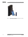
Figure 1.
8 (40)
Product example: Nokia MW1324 and Nokia C111 Wireless
LAN card & antenna (optional)
© Nokia Networks Oy
Nokia Proprietary and Confidential
DN01154358
Issue 1-0 en
Preparations
3
Preparations
You must have all the necessary hardware and software installed before you can
access the Internet with your gateway. See the list below.
3.1
3.2
What you need to access the Internet
•
Correctly configured PC, equipped with 10Base-T Ethernet Card
•
Operational DSL line (contact your ISP to make sure that DSL services are
available)
•
User account provided by your ISP
•
Nokia M/MW gateway which is configured according to your ISP's
instructions
•
All the accessories included in the gateway's sales package
•
Web browser (Netscape Navigator, Microsoft Internet Explorer or
equivalent)
•
MW models only: If you want to use the wireless feature, you must have
wireless LAN adapters installed in all the computers which will be used in
your wireless network.
•
MW1324 only: If you want to utilise the HomePNA feature, you either
need a HomePNA adapter or a preconfigured PC.
Check the contents of the package
Check that the gateway and the items delivered with it are undamaged.
The package contains the following items:
DN01154358
Issue 1-0 en
•
Gateway
•
Wireless LAN card and antenna (MW series only, optional)
© Nokia Networks Oy
Nokia Proprietary and Confidential
9 (40)
Nokia M/MW Gateways M1112, M1122, MW1112, MW1122, MW1324, MW1352
•
DSL line cable
•
10Base-T Ethernet cable
In M models, straight through Ethernet cables are used
In MW models, crossover Ethernet cables are used
3.3
•
Power cord
•
Serial adapter
•
User Manual
Get acquainted with your gateway's indicator
lights and connectors
Indicator lights
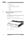
There are six (MW1324: seven) indicator lights in the front panel: DSL, HPNA
(MW1324 only), ETH, COL, WLAN, STA and PWR. STA indicator is red. The
other indicators are green.
The indicator lights are located in the gateway's front panel.
MW1324 only
Figure 2.
10 (40)
PWR
STA
WLAN
COL
ETH
HPNA
DSL
Models M1112 and M1122 have four ETH indicator lights (ETH1–ETH4) in the
front panel.
MW series only
Front panel indicators
© Nokia Networks Oy
Nokia Proprietary and Confidential
DN01154358
Issue 1-0 en
Preparations
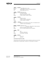
DSL
GREEN
Off
Blinks
On
HPNA
ADSL/SHDSL link is down.
ADSL/SHDSL connection is being established.
ADSL/SHDSL link is up.
GREEN (MW1324 only)
Off
On
Blinks
ETH
No stations detected.
Stations detected but no traffic.
Traffic detected at HPNA interface.
GREEN
Off
On
Blinks
COL
Ethernet is down.
10Base-T Ethernet is functional.
Traffic detected on Ethernet.
GREEN
Blinks
WLAN
Collisions on the Ethernet. Note, that it is normal that some
collisions occur on the Ethernet.
GREEN (MW series only)
Off
On
Blinks
STA
Off
On
Blinks
PWR
Off
On
No stations on the WLAN, or WLAN PC Card not inserted.
Stations on the WLAN but no traffic.
Receives traffic through the WLAN interface.
RED
OK
Hardware malfunction.
The gateway is booting.
GREEN
Power off.
Power on.
Connectors and power switch
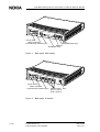
The gateway's power switch, mains connector and data connectors are located in
the back panel. For MW models, see figure 3. For M models, see figure 4.
DN01154358
Issue 1-0 en
© Nokia Networks Oy
Nokia Proprietary and Confidential
11 (40)
Nokia M/MW Gateways M1112, M1122, MW1112, MW1122, MW1324, MW1352
Power switch
Mains connector
Command line interface (CLI)
Figure 3.
DSL
HPNA (MW1324 only)
Ethernet
WLAN (PC card)
Back panel, MW models
Power switch
Mains connector
Command line interface (CLI)
Figure 4.
12 (40)
Ethernet ports DSL
(ETH-1, ETH-2,
ETH-3, ETH-4)
Back panel, M models
© Nokia Networks Oy
Nokia Proprietary and Confidential
DN01154358
Issue 1-0 en
Physical installation
4
Physical installation
4.1
Placing the gateway on a table or desk
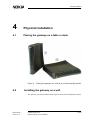
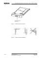
Figure 5.
4.2
Placing the gateway in a vertical (A) or horizontal (B) position
Installing the gateway on a wall
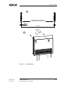
The gateway can also be wall mounted. Figure 6 shows the installation procedure.
DN01154358
Issue 1-0 en
© Nokia Networks Oy
Nokia Proprietary and Confidential
13 (40)
Nokia M/MW Gateways M1112, M1122, MW1112, MW1122, MW1324, MW1352
Depending on the wall material, you may have to drill holes and use plastic plugs
to install the gateway on the wall. Certain wall materials do not require drilled
holes or plugs.
WARNING
Before drilling and/or fixing the screws, make sure that there are no electric
cables, phone cables, waterpipes or any other objects at the drilling points
inside the wall. Electric cables and telephone cables carry voltages which can
cause dangerous electric shocks.
If drilling holes and the use of plugs are required, do the following:
1.
Drill two holes (6 mm in diameter) on the wall. The distance between the
holes must be 155 mm.
2.
Insert the plugs into the holes.
3.
Fix the screws.
4.
Mount the gateway on the wall as shown in Figure 6. Make sure the
gateway is seated firmly.
If drilling and plugs are not required, do the following:
14 (40)
1.
Fix the screws on the wall. Do not use plugs. The distance between the
screws must be 155 mm.
2.
Mount the gateway on the wall as shown in Figure 6. Make sure the
gateway is seated firmly.
© Nokia Networks Oy
Nokia Proprietary and Confidential
DN01154358
Issue 1-0 en
Physical installation
1.
If drilled holes are needed,
insert these plugs into the holes.
6 mm
155 mm
2.
Figure 6.
DN01154358
Issue 1-0 en
Wall installation
© Nokia Networks Oy
Nokia Proprietary and Confidential
15 (40)
Nokia M/MW Gateways M1112, M1122, MW1112, MW1122, MW1324, MW1352
4.3
Connecting the data cables (and WLAN cards)
WARNING
Do not connect the gateway's power cord yet!
Note
If you are using WLAN cards, note that the installation procedure described
below only covers the physical installation of the WLAN cards.
Before you can use your gateway's wireless feature, you must first install Nokia
C110/C111 WLAN card software on your computer. The software and
installation guide are delivered with the optional Nokia C110/C111 WLAN card.
Connect the data cables
1.
Connect the 8-pin Ethernet cable between the computer's Ethernet card and
the gateway's Ethernet connector located in the gateway's back panel.
Steps 2 and 3 are for MW1324 only.
2.
If you use a splitter with your MW1324, connect an additional DSL/HPNA
cable (RJ-12) between the HPNA connector of your MW1324 and a phone
wall socket after the splitter.
If you use a microfilter before each phone, you do not need to install the
additional DSL/HPNA cable. In such a case, leave the HPNA connector
unconnected. (The HPNA signal uses the same cable as ADSL, so no
additional cabling is needed.)
16 (40)
3.
Connect each PC in your home network to your home phoneline network
(without microfilters). Your PC's must be equipped with HPNA network
adapters.
4.
Connect the 6-pin DSL cable between the gateway's DSL connector and
your DSL phone wall socket.
© Nokia Networks Oy
Nokia Proprietary and Confidential
DN01154358
Issue 1-0 en
Physical installation
MW models only: connect the WLAN cards
1.
Insert one WLAN card gently into the card slot located in the back panel of
the gateway.
2.
Insert the other WLAN card(s) gently into the WLAN card slot(s) of your
PC(s).
Connect the gateway's power cable
1.
Plug the gateway's power cord into the mains connector located in
gateway's back panel.
2.
Connect the gateway's power cord plug into an earthed wall mains socket.
3.
Switch on the power on your gateway.
Use filters if you want to use telephone and Internet simultaneously
Use in-line filters to block the high-frequency signals (data) from travelling
through the phone cord to your telephone, fax or answering machine. DSL and
HomePNA use the high bandwidth of your telephone line to transmit and receive
data.
Use approved filters only and install them according to the manufacturer's
instructions.
4.4
Installing an external WLAN antenna (MW series
only)
To obtain a better coverage for your wireless network, you can use external
antennas.
With Nokia C111 WLAN card, up to two external antennas can be used.
If you use only one external antenna, connect the external antenna to the right
antenna connector of the wireless LAN card. See figure 7.
Install the external antenna on the wall or on the ceiling according to figure 8. For
further information, refer to the WLAN card User's Guide.
DN01154358
Issue 1-0 en
© Nokia Networks Oy
Nokia Proprietary and Confidential
17 (40)
Nokia M/MW Gateways M1112, M1122, MW1112, MW1122, MW1324, MW1352
18 (40)
Figure 7.
External antenna connector
Figure 8.
External antenna installation
© Nokia Networks Oy
Nokia Proprietary and Confidential
DN01154358
Issue 1-0 en
Configuring your PC(s) and gateway for use
5
Configuring your PC(s) and gateway for
use
This chapter describes briefly the basic configuration of your PC and gateway so
that they can communicate with each other.
You must create a connection between your PC and gateway.
For the connection, you need a browser (Netscape Navigator, Microsoft Internet
Explorer or equivalent).
Once a connection between your gateway and PC is established, you have access
to the gateway's web page.
After you have made all the necessary configurations for your gateway and PC,
you are ready to use the Internet.
Before proceeding, take some time to check that all the cables are properly
connected and that your PC is set up properly.
5.1
Finding out the gateway's IP address or name
The gateway has a web interface with which you can configure the gateway and
view the gateway's web pages.
First, you have to create a connection between your PC and the gateway.
For this, you need to know either the gateway's IP address or the name assigned
to it.
You have two options:
Your ISP has given a fixed IP address for the gateway. Use this address for the
browser connection.
or
DN01154358
Issue 1-0 en
© Nokia Networks Oy
Nokia Proprietary and Confidential
19 (40)
Nokia M/MW Gateways M1112, M1122, MW1112, MW1122, MW1324, MW1352
Your gateway uses Dynamic Host Configuration Protocol (DHCP) and Domain
Name Server. In this case the name is M1112, M1122, MW1112, MW1122,
MW1324 or MW1352, depending on the model.
To find out the IP address, you can also run winipcfg.exe (Windows 95/98/Me)
or ipconfig.exe (Windows 2000/NT). See the instructions below.
To find out the IP address in Win95/98/Me
1.
Click Start, and then click Run.
2.
In the Open box, type:
3.
winipcfg (IP dialog box opens)
4.
Now the program displays the IP parameters on the screen. Default
Gateway is your gateway's IP address. Use this address for the browser
connection.
To find out the IP address in Windows NT and Windows 2000
5.2
1.
Click Start , and then click Run.
2.
In the Open field, type cmd. A DOS box opens.
3.
In the DOS box, type ipconfig.
4.
Now the program displays the IP parameters on the screen. The Default
Gateway is your gateway's IP address. Use this address for the browser
connection.
Opening a connection to the gateway with a
browser
To create a connection, do the following
1.
20 (40)
Open the web browser (Netscape Navigator, Microsoft Internet Explorer or
equivalent).
© Nokia Networks Oy
Nokia Proprietary and Confidential
DN01154358
Issue 1-0 en
Configuring your PC(s) and gateway for use
2.
Switch on your gateway. The booting takes a few moments during which
some of the gateway's indicator lights blink.
After booting, the PWR and ETH lights should remain lit. If this does not
happen, see Chapter 7 Troubleshooting.
3.
Enter the IP address or name of your gateway in the Address (Internet
Explorer) or Location/Go to (Netscape Navigator) field of the browser.
In the example presented in figure 9, Netscape Navigator and the default
gateway address, as shown by the ipconfig command, is used.
Figure 9.
Opening a connection to the gateway using an IP address
4.
Press Enter on your keyboard.
5.
Enter username and password which were provided by your ISP. If no
username/password is required, just click OK to prodeed.
6.
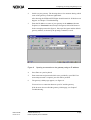
The gateway's Main page appears, see figure 10.
You now have a connection between your PC and the gateway.
If the browser does not find the gateway's Main page, see Chapter 7
Troubleshooting.
DN01154358
Issue 1-0 en
© Nokia Networks Oy
Nokia Proprietary and Confidential
21 (40)
Nokia M/MW Gateways M1112, M1122, MW1112, MW1122, MW1324, MW1352
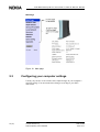
Main Page
Figure 10. Main page
5.3
Configuring your computer settings
Usually, all you have to do is make some simple changes in your computer's
network settings. You must make these changes according to your ISP's
instructions.
22 (40)
© Nokia Networks Oy
Nokia Proprietary and Confidential
DN01154358
Issue 1-0 en
Basic WLAN configurations (MW models only)
6
Basic WLAN configurations (MW models
only)
If you are using WLAN, you may have to change some of your wireless network
settings.
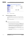
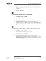
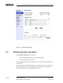
You find these settings on the Wireless LAN and WLAN Clients web pages
presented in figures 11 and 12.
If you have purchased your gateway from a store, you may need to make more
configurations. For further information, consult your ISP.
6.1
Changing the wireless LAN settings
On the Wireless LAN page you can change the following settings:
•
Network name
•
Regulatory domain
•
Radio channel
•
Transmit power level
You can activate the new settings by clicking the Apply button.
If you want to save the new settings, first go to Save config page and click Save
configuration.
DN01154358
Issue 1-0 en
© Nokia Networks Oy
Nokia Proprietary and Confidential
23 (40)
Nokia M/MW Gateways M1112, M1122, MW1112, MW1122, MW1324, MW1352
Figure 11. Wireless LAN page
6.2
Enabling admission control
On the WLAN Clients page you can enable access control based on the MAC
addresses of the wireless LAN clients (that is the PC's or laptops in your wireless
network).
When access control is enabled, only the wireless stations on the client table have
access to your wireless network.
To add a client in the client table, do the following:
24 (40)
1.
Choose a name for the wireless client and write it in the Name field. (The
fields used for adding new clients are located next to the Add new button).
2.
Write the client's MAC address in the MAC address field. Depending on
your Windows version, refer to the instrustions below on how to find out
the MAC address(es) of the computer(s) in your wireless network.
3.
Select the encryption key length from the WEP key length menu. If you
select the key length (that is, your choice is other than “None”), you must
also enter the encryption key.
4.
Select the Client table MAC address option from the Admission method
pull-down menu.
© Nokia Networks Oy
Nokia Proprietary and Confidential
DN01154358
Issue 1-0 en
Basic WLAN configurations (MW models only)
5.
Select the encryption method you want to use for this client from the
Encryption pull-down menu. For more information on encryption, refer to
section 6.3.
6.
Click the Apply button.
To find out the MAC address in Win95/98/Me
1.
Click Start, and then click Run.
2.
In the Open box, type:
3.
winipcfg (IP dialog box opens)
4.
Now the program displays the IP parameters on the screen. The
information you need is “Adapter Address”. Use this address (called MAC
address in your gateway) when creating an access list on WLAN clients
page.
To find out the MAC address in Windows NT and Windows 2000
DN01154358
Issue 1-0 en
1.
Click Start , and then click Run.
2.
In the Open field, type cmd. A DOS box opens.
3.
In the DOS box, type ipconfig/all.
4.
Now the program displays the IP parameters on the screen. The
information you need is Ethernet adapter´s “Physical Address” . Use this
address (called MAC address in your gateway) when creating an access list
on WLAN clients page.
© Nokia Networks Oy
Nokia Proprietary and Confidential
25 (40)
Nokia M/MW Gateways M1112, M1122, MW1112, MW1122, MW1324, MW1352
Figure 12. WLAN clients page
6.3
Enabling wireless encryption
On the WLAN Clients page you can also:
•
activate Wired Equivalent Privacy (WEP) encryption
•
set the encryption key parameters
It is recommended that you use encryption in your wireless network and use an
encryption key.
Ensure that wireless LAN clients (that is, the wireless devices you want to use in
your network) have the same configuration as the wireless LAN card in the
gateway and that they are in the Infrastructure mode.
26 (40)
© Nokia Networks Oy
Nokia Proprietary and Confidential
DN01154358
Issue 1-0 en
Basic WLAN configurations (MW models only)
When you have set the network name to your wireless client, the wireless
connection is established and the WLAN indicator on the gateway's front panel
lights up.
DN01154358
Issue 1-0 en
© Nokia Networks Oy
Nokia Proprietary and Confidential
27 (40)
Nokia M/MW Gateways M1112, M1122, MW1112, MW1122, MW1324, MW1352
28 (40)
© Nokia Networks Oy
Nokia Proprietary and Confidential
DN01154358
Issue 1-0 en
Troubleshooting
7
Troubleshooting
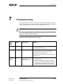
This chapter informs you how to correct the most common problems you may
encounter when using your gateway. If you cannot find a solution to the problem,
contact your ISP or the store from which you bought the gateway.
WARNING
Do not try to repair the gateway yourself. The gateway does not contain any
user-serviceable parts. Do not open or remove the gateway covers. There are
dangerous voltages inside the gateway.
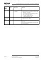
Problems indicated by the front panel lights
Front
panel
light
Status
Description
Solution
PWR
Off
Power is off.
1. Switch the power on.
2. Check the power cable.
STA
Solid red
Hardware malfunction
1. Switch the power off.
2. Pull the power cord out of the wall socket.
3. Contact your ISP's help desk.
Note that during startup the red STA indicator blinks.
This is normal.
WLAN (MW
models
only)
Off
No active WLAN
clients (PC's, laptops
etc.) in range
1. Check the WLAN card instructions of the gateway
and of the client.
2. Bring your WLAN client closer to your gateway.
3. Check your WLAN client installation and settings
(radio channel, network name, etc.). See the
WLAN client's user manual for further assistance.
DN01154358
Issue 1-0 en
© Nokia Networks Oy
Nokia Proprietary and Confidential
29 (40)
Nokia M/MW Gateways M1112, M1122, MW1112, MW1122, MW1324, MW1352
Front
panel
light
Status
Description
Solution
ETH
Off
No Ethernet
connection
1. Check that the computer is operating.
2. Check the Ethernet cable. Use the Ethernet cable
provided in the package.
If you have purchased the cable yourself, check
that the cable type is correct:
- M series: straight through type
- MW series: crossover type
HPNA
(MW1324
only)
Off
DSL
Off
No stations detected
1. Check that the computer is operating.
2. Check the HPNA cabling.
DSL link is down
It takes 1 to 10 minutes for the DSL line to become
operative.
If the DSL indicator light is off after this period, contact
your ISP's help desk.
30 (40)
© Nokia Networks Oy
Nokia Proprietary and Confidential
DN01154358
Issue 1-0 en
Technical specifications
Appendix A. Technical specifications
A.1
Technical specifications
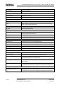
Features
ADSL (MW1122, MW1324)
Physical layer
ANSI T1.413 Issue 2 (ANSI ADSL), ITU-T G.992.1 (ITU-T ADSL), ITU-T
G.992.2 (G.lite), and ITU-T G.994.1 (Handshake) compatible
ADSL (M1112, MW1112)
Physical layer
ETSI TS 101 388 compatible
ADSL line connector(all models)
RJ-12
ATM over ADSL (all models except MW1352)
ATM connections
PVC, up to 8 virtual circuits for data
Service categories
UBR
Encapsulations
RFC2684 ETH-LLC, RFC2684 IP-LLC,
RFC2364 PPP-VC, RFC2364 TUNNELLED-PPP-VC, RFC2516 PPPoELLC
SHDSL (MW1352 only)
Physical layer
ITU-T G.991.2 (ITU-T SHDSL)
SHDSL line connector
RJ-12
ATM over SHDSL (MW1352 only)
ATM connections
PVC, up to 8 virtual circuits
Service categories
UBR
Encapsulations
RFC2684 ETH-LLC, RFC2684 IP-LLC, RFC2364 PPP-VC, RFC2364
TUNNELED-PPP-VC, PPPoE-LLC
Ethernet interface
Ethernet
10Base-T, half duplex
Encapsulation
DIXv2 (transmit), IEEE 802.3 and DIXv2 (receive)
Ethernet connectors
RJ-45
HomePNA 2.0 interface (MW1324 only)
HPNA
Half duplex, 4 - 16 Mbit/s
Modes
HPNA 1.0, 1.1 and 2.0 specifications data rates up to 16 Mbit/s
DN01154358
Issue 1-0 en
© Nokia Networks Oy
Nokia Proprietary and Confidential
31 (40)
Nokia M/MW Gateways M1112, M1122, MW1112, MW1122, MW1324, MW1352
Encapsulation
Ethernet compatible
Connector
RJ-12
Wireless LAN interface (MW models only)
Wireless LAN
IEEE 802.11b DSSS
Data connector
PC Card slot type 2
Routing
Routing protocols
RIPv1, RIPv2, and static routes
Other
NAPT, IGMP proxy, DHCP server, DHCP relay, DHCP client, DNS relay,
PPTP local tunnelling, PPPoE client
Class of Service
Weighted fair queueing
Firewall
Stateful inspection firewall
Bridging
Bridging
Self-learning bridge, bridges between all interfaces. Possibility to disable
bridging between WAN interfaces.
MAC table
1024 entries
Class of Service
Weighted fair queueing
Command line interface (CLI) for local management
Physical layer
Electrically RS-232, TxD, RxD and GND signals
Data format
Asynchronous, 8+no parity + 1 stop bit (8-N-1)
Bit rate
9600 bps
Flow control
None
CLI connector
RJ-45
Dedicated ATM management channel
Service categories
UBR
Encapsulations
RFC2684 ETH-LLC, RFC2684 IP-LLC, RFC2364 PPP-VC
IP addressing
Statically configured
Through IPCP when PPP over ATM is used
Routing
Static routes
RIPv1, RIPv2
Management protocols
Telnet/TCP/IP for command line interface,
TFTP/UDP/IP for software and configuration download, HTTP/web server
Management through payload
Management protocols
Telnet/TCP/IP for command line interface,
TFTP/UDP/IP for software and configuration download, HTTP/web server
32 (40)
© Nokia Networks Oy
Nokia Proprietary and Confidential
DN01154358
Issue 1-0 en
Technical specifications
Indicator lights
DSL
ADSL line status
HPNA (MW1324 only)
HomePNA activity and status
ETH
Ethernet activity and status
COL
Ethernet collision
WLAN
WLAN activity and status
STA
M/MW startup
PWR
Power on
Mechanical construction and power supply
Width
255 mm
Height
65 mm
Depth
230 mm
Weight
1 kg
Mains connection
Voltage
100 Vrms-240 Vrms AC (nominal values)
Frequency
50/60 Hz
Power consumption
10 W
Ambient confitions, EMC and safety
Operating temperature
5 to 45°C
Humidity
10% to 90%, non-condensing
EMC
M/MW complies with the following specifications provided that the device is connected to an earthed socket
outlet.
Emission
EN55022: 1998 class B
Immunity
EN55024: 1998
EMC
EN300286–2: 1997, FCC part 15 class B
Overvoltage
ITU-T K.21, FCC PART 68
Safety
Safety
DN01154358
Issue 1-0 en
EN 60950, UL 1950, 3rd edition
© Nokia Networks Oy
Nokia Proprietary and Confidential
33 (40)
Nokia M/MW Gateways M1112, M1122, MW1112, MW1122, MW1324, MW1352
34 (40)
© Nokia Networks Oy
Nokia Proprietary and Confidential
DN01154358
Issue 1-0 en
Glossary
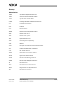
Abbreviations
ADSL
Asymmetric Digital Subscriber Line
ANSI
American National Standards Institute
ATM
Asynchronous Transfer Mode
CHAP
Challenge Handshake Authentication Protocol
CLI
Command Line Interface
COL
Collision
CoS
Class of Service
DHCP
Dynamic Host Configuration Protocol
DNS
Domain Name Server
DNS
Domain Name System
DSL
Digital Subscriber Line
EMC
Electromagnetic Compatibility
ETH
Ethernet
ETSI
European Telecommunications Standards Institute
FCC
Federal Communications Commission
FTP
File Transfer Protocol
HPNA
Home Phone Line Network Alliance
HTTP
HyperText Transfer Protocol
ICMP
Internet Control Message Protocol
IGMP
Internet Group Management Protocol
IP
Internet Protocol
IPCP
Internet Protocol Control Protocol
ISDN
Integrated Services Digital Network
ISP
Internet Service Provider
DN01154358
Issue 1-0 en
© Nokia Networks Oy
Nokia Proprietary and Confidential
35 (40)
Nokia M/MW Gateways M1112, M1122, MW1112, MW1122, MW1324, MW1352
ITU-T
International Telecommunication Union - Telecommunication Standardization
Sector
LAN
Local Area Network
LLC
Logical Link Control
MAC
Media Access Control
NAPT
Network Address and Port Translation
PAP
Password Authentication Protocol
PPP
Point-to-Point Protocol
PPPoE
PPP over Ethernet
PPTP
Point-to-Point Tunnelling Protocol
PVC
Permanent Virtual Circuit
PWR
Power
RFC
Request For Comments
RIP
Routing Information Protocol
SHDSL
Single pair High bit rate Digital Subscriber Line
SIF
Stateful Inspection Firewall
SNMP
Simple Network Management Protocol
STA
Status
TCP
Transmission Control Protocol
TC-PAM
Trellis Coded Pulse Amplitude Modulation.
TFTP
Trivial File Transfer Protocol
UBR
Unspecified Bit Rate
UDP
User Datagram Protocol
VCC
Virtual Channel Connection
VPN
Virtual Private Network
WAN
Wide Area Network
36 (40)
© Nokia Networks Oy
Nokia Proprietary and Confidential
DN01154358
Issue 1-0 en
WEP
Wired Equivalent Privacy
WFQ
Weighted Fair Queueing
WLAN
Wireless Local Area Network
WWW
World Wide Web
Terms
10Base-T
10 Mbit/s Ethernet LAN specification using two pairs of twisted cabling. 10BaseT is a part of the IEEE 802.3 specification.
Authentication
Determining the identity of a user that is attempting to access a network.
Asymmetric digital
subscriber line,
ADSL
High-speed transmission technology using existing copper telephone lines. Data
is transmitted in general from a server to a user.
Bridge
Device or software that transmits data from a source network to a destination
network. These two networks normally use the same protocol.
Broadcast
Transmitting data to everyone on the network. Rf. multicast.
Command line
interface, CLI
Character-based man-machine interface for configuring a device.
Digital subscriber
line, xDSL
Generic abbreviation for various different DSL types. For example ADSL,
HDSL, SDSL, and VDSL.
Domain name
server, DNS
Server used on the Internet for translating names of network nodes into IP
addresses. A name server lets users access networks nodes by name instead of
having to remember IP address numbers.
Domain name
system, DNS
System containing domain name servers.
Encapsulation
Method for using multiple protocols within the same network. This is done by
enclosing a data unit of one protocol into a data unit of another protocol.
Encryption
For data security, transforming data into an unreadable form to prevent any but
the intended receiver from reading it.
Encryption key
Character or bit sequence which is used for encryption, decryption or
authentication of data.
Ethernet
Local area network that connects devices like computers, printers, and terminals.
Ethernet operates over twisted-pair or coaxial cable.
Gateway
Device or software in an information network which links two networks that use
differents communications protocols.
DN01154358
Issue 1-0 en
© Nokia Networks Oy
Nokia Proprietary and Confidential
37 (40)
Nokia M/MW Gateways M1112, M1122, MW1112, MW1122, MW1324, MW1352
HomePNA, HPNA
Technology for the home network based on Ethernet and using existing phone
lines. Voice and data travel on the same wires without interfering with each other.
IP address
Numerical identification individualising a device connected to the Internet or a
network. For example 192.168.1.2.
Local area network,
LAN
Data transmission network covering a small area, for example a flat or a house.
Usually based on Ethernet technology.
MAC address
Unique fixed address of a piece of hardware, normally set at the time of
manufacture and used in LAN protocols.
Multicast
Transmitting data to a select group of recipients at the same time, for example
sending an e-mail message to a mailing list. Rf. broadcast.
Network address
port translation,
NAPT
Method by which IP addresses and translating transport identifiers (for example
TCP and UDP port numbers, ICMP query identifiers) are mapped from one
address realm to another, providing transparent routing to end hosts.
Packet Internet
Groper, ping
Program used to test whether a particular network destination is accessible, by
sending an ICMP (Internet control message protocol) echo request and waiting
for a response. Ping is used primarily to troubleshoot Internet connections.
Ping
See Packet Internet Groper.
Proxy server
Server which retrieves information from the Internet and stores the information
that users frequently use to speed up the retrieval. For example, in using the web
the proxy server speeds up the downloading of those web pages located behind
slow or congested network connections.
Request for
comments, RFC
Document series which describes the Internet suite of protocols and related
experiments.
Router
Device or software which transmits data from a source network to a destination
network in accordance with an address.
Single pair high bit
rate digital
subscriber line,
SHDSL
High-speed transmission technology using existing copper telephone lines.
Stateful inspection
firewall, SIF
Firewall which provides access control at the network layer by inspecting the
contents of incoming packets and accepting or rejecting them depending upon
their content.
Subnet mask
Numerical indentification used to determine what subnetwork an IP address
belongs to, for example 255.255.255.0.
Tunnelling
Technique to improve the rate, reliability, and security of transmission in a
network by creating for transmission a permanent connection, called tunnel,
which is often secured by encryption.
38 (40)
© Nokia Networks Oy
Nokia Proprietary and Confidential
DN01154358
Issue 1-0 en
Unspecified bit rate,
UBR
Quality of service QoS where there are no guarantees in terms of data loss rate
and delay. UBR is very efficient, but not used for critical data.
Vbridge
Gateway/bridge management interface used as a bridge host interface or gateway
interface depending on the operation mode On the gateway's web pages, the
VBRIDGE is called gateway or bridge IP interface.
Virtual private
network, VPN
Network which is constructed by using a public information network and which
uses encryption. The terminal equipment can be situated all over the world but
they function as if they were connected to a local area network LAN.
Weighted fair
queueing, WFQ
Traffic management technique which controls transmission bandwidth allocation
determined by the bandwidth needed for the traffic flow.
Wide area network,
WAN
Data communications network that serves users across a broad geographic area.
Wi-Fi, Wireless
Fidelity
Wireless LAN standard (IEEE 802.11b) developed to maximise multi-vendor
interoperability as well as to introduce a variety of performance improvements
and benefits to the wireless networking technology.
Wired equivalent
privacy, WEP
Security protocol used to provide data security by encrypting data over radio
waves. The WEP is defined in IEEE 802.11 standard and it is designed to provide
the same level of security as that of a wired LAN.
Wireless LAN Card,
Nokia C111
Card which enables to wirelessly connect compatible laptop computers, handheld devices, desktop PCs, and other devices with a type II or II PC card slot to a
wired local area network through an access point.
Wireless local area
network, WLAN
Local area network using wireless connections as transmission path.
WLAN clients
The wireless devices (for example PC's and laptops) inside your wireless
network.
DN01154358
Issue 1-0 en
© Nokia Networks Oy
Nokia Proprietary and Confidential
39 (40)
Nokia M/MW Gateways M1112, M1122, MW1112, MW1122, MW1324, MW1352
40 (40)
© Nokia Networks Oy
Nokia Proprietary and Confidential
DN01154358
Issue 1-0 en