1
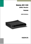
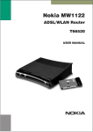
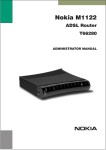
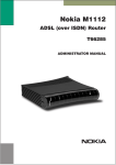
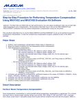
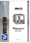
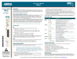
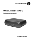
Nokia M5122
ADSL Bridgeā
T66250
USER MANUAL
Nokia M5122
ADSL Bridge
User Manual
C33874.21 B0
02.11.2000
1
Introduction to Nokia M5122
Nokia M5122 is an ADSL bridge which enables high-speed Internet
access and LAN interconnection. It increases the capacity of the
already installed telephone lines used traditionally for telephone
services. M5122 enables high-speed connections for homes and small
offices.
Figure 1
Nokia M5122
Nokia M5122 allows multiple PCs equipped with a 10Base-T Ethernet
interface to be connected to a remote network via a Digital Subscriber
Line Access Multiplexer (DSLAM) and an ATM access network. It
acts as a bridge between the Ethernet LAN and ADSL/ATM network
interfaces. An in-built 4-port hub allows easy home and small office
network installation.
C33874002SE_A0
E Copyright Nokia Networks Oy
1
Nokia M5122 User Manual
2
Installing M5122
Before installing M5122, you may want to familiarise yourself with
the interfaces and indicator lights of M5122. From section 2.3, you
will find a step-by-step installation procedure, which shows the
physical installation of M5122.
2.1
Interfaces
M5122 has one ADSL line interface and four Ethernet interfaces
(10Base-T). It also has a Command Line Interface (CLI) for
management purposes. The ADSL line interface is compatible with
ITU-T G.992.1 specification.
Power switch
Mains connector
Command line interface (CLI)
Figure 2
2.2
ADSL line (DSL)
Ethernet ports
(ETH-1, ETH-2,
ETH-3, ETH-4)
M5122 back panel
Indicator lights
M5122 has eight indicator lights on the front panel: PWR, STA, COL,
ETH-1, ETH-2, ETH-3, ETH-4, and DSL. STA indicator is red. Other
indicators are green.
2
E Copyright Nokia Networks Oy
C33874002SE_A0
Figure 3
DSL
Off
Blinks
On
ETH-
Off
On
Blinks
COL
Blinks
STA
Off
On
PWR
Off
On
C33874002SE_A0
M5122 front panel indicators
GREEN
ADSL link is down.
ADSL connection is being established.
ADSL link is up.
GREEN
Ethernet is down.
10Base-T Ethernet is functional.
Receives traffic from Ethernet.
GREEN
Collisions on the Ethernet. Note, that it is normal that some
collisions occur on the Ethernet.
RED
OK
Hardware malfunction during startup.
GREEN
Power off.
Power on.
E Copyright Nokia Networks Oy
3
Nokia M5122 User Manual
2.3
Step-by-step installation procedures
In this section, we present two installation procedures: ADSL data
services and Telephone and ADSL data services. To use both telephone
and ADSL services, you will need a POTS splitter. This manual gives
installation example for a Nokia splitter T66270.
In these examples, we assume that you have installed your Ethernet
card properly and that your service provider has provided you with
instructions how to set your PC’s networking options.
ADSL data services
2.
1.
3.
4.
Figure 4
5.
M5122 with cables connected (ADSL services only)
1. Plug the mains power cord to a mains outlet. M5122 can be
connected to an earthed socket outlet only.
2. Switch on M5122. The PWR indicator lights up. After a while, the
red STA indicator blinks and then remains unlit. M5122 is now
functional.
3. Connect the Ethernet cable between your PC’s 10Base-T
connector and the Ethernet connector on the M5122 back panel
(ETH-1, ETH-2, ETH-3, or ETH-4).
4. Switch on your PC. The indicator corresponding the Ethernet port
you connected your PC to becomes green when your PC has
started. This indicator blinks when there is traffic in the
corresponding Ethernet port.
4
E Copyright Nokia Networks Oy
C33874002SE_A0
5. Connect the ADSL line cable between the DSL connector on the
M5122 back panel and the wall socket. After a while, the DSL
indicator starts blinking. This indicates that the ADSL line is being
established. When the DSL indicator remains lit, the line is
functional.
6. During normal operation PWR and DSL indicators are lit and the
Ethernet indicators of the active Ethernet ports blink or remain lit
depending whether there is traffic or not. COL indicator may blink
occasionally during normal operation.
C33874002SE_A0
E Copyright Nokia Networks Oy
5
Nokia M5122 User Manual
Telephone and ADSL data services with T66270 splitter
2.
1.
3.
7.
5.
4.
6.
Figure 5
M5122 with cables and splitter (T66270) connected
(Telephone and ADSL services)
1. Plug the mains power cord to a mains outlet. M5122 can be
connected to an earthed socket outlet only.
2. Switch on M5122. The PWR indicator lights up. After a while, the
red STA indicator blinks and then remains unlit. M5122 is now
functional.
3. Connect the Ethernet cable between your PC’s 10Base-T
connector and the Ethernet connector on the M5122 back panel
(ETH-1, ETH-2, ETH-3, or ETH-4).
4. Switch on your PC. The indicator corresponding the Ethernet port
you connected your PC to becomes green when your PC has
started. This indicator blinks when there is traffic in the
corresponding Ethernet port.
5. Connect the ADSL line cable between the DSL connector on the
M5122 back panel and the splitter’s MODEM connector.
6. Connect the splitter cable between the splitter’s LINE connector
and the wall socket. After a while, the DSL indicator starts
blinking. This indicates that the ADSL line is being established.
When the DSL indicator remains lit, the line is functional.
7. Connect the telephone to the splitter’s PHONE connector.
6
E Copyright Nokia Networks Oy
C33874002SE_A0
8. During normal operation PWR and DSL indicators are lit and the
Ethernet indicators of the active Ethernet ports blink or remain lit
depending whether there is traffic or not. COL indicator may blink
occasionally during normal operation.
Now your M5122 has been connected and you can configure your PC’s
networking options and check that the service works according to your
service provider’s instructions.
2.4
Troubleshooting
This section gives some tips for troubleshooting.
Power (PWR) indicator is unlit.
Make sure that power cord has been connected to a mains outlet and
M5122 has been switched on.
Red status (STA) indicator is lit
Switch power off and then on again. If the STA indicator remains lit,
the unit may be faulty.
ADSL (DSL) indicator is unlit
Make sure that the ADSL line cable has been properly connected
between the DSL connector and the wall socket.
Ethernet (ETH-) indicator is unlit
Make sure that the Ethernet cable has been properly connected
between your PC’s Ethernet interface and the M5122 ETH connector.
Make sure that your PC is ON.
You cannot access the Internet
1. Make sure that your M5122 is ON.
2. Check that the DSL indicator is lit.
3. Check that Ethernet indicator (ETH-1, ETH-2, ETH-3, or ETH-4)
corresponding to the Ethernet interface you are connected to is
ON.
4. Make sure that your PC’s networking functions have been
configured according to your service provider’s instructions.
C33874002SE_A0
E Copyright Nokia Networks Oy
7
Nokia M5122 User Manual
2.5
Installing M5122 on the wall
M5122 can also be wall mounted. Figure 6 shows the installation
procedure.
1. Drill two holes (6 mm in diameter) on the wall. The distance
between the holes must be 155 mm. Insert the plugs to the holes
and fix the screws.
2. Mount the modem on the wall as shown in Figure 6.
1.
6 mm
155 mm
2.
Figure 6
8
Wall installation
E Copyright Nokia Networks Oy
C33874002SE_A0
3
Configuring M5122
Your service provider has configured your M5122 for the service. Do
not change settings unless specifically asked by your service
provider. You can change M5122 settings with an ordinary web
browser, such as Microsoft Internet Explorer or Netscape Navigator.
Use a PC connected to an ETH port of M5122 for configuration. In this
case the corresponding ETH indicator should be lit.
3.1
Browser management
The web configuration pages of M5122 can be accessed through the
Ethernet and through the ADSL/ATM channels of M5122. In order to
access the web management feature, the IP functionality must be
activated and an IP address must be given to the corresponding
interface.
You can use your PC’s web browser software to access the web
configuration pages in M5122. To access the web pages you must
know the IP address of your M5122 or, alternatively, the “name” that
your M5122 recognises.
Note
Before using your web browser for configuration, you must know the
IP address or the name assigned to your M5122.
There are three ways to find out whether to use a name or an IP address:
D
D
D
3.1.1
Your service provider has given you an IP address for M5122.
Your M5122 uses Dynamic Host Configuration Protocol (DHCP)
and Domain Name Server. In this case the name is M5122.
Your M5122 uses DHCP. In this case run winipcfg.exe (Windows
95) or ipconfig.exe (Windows NT). The IP address of M5122 is the
Default Gateway address shown by the ipconfig program.
Opening a connection
To open a connection to the Nokia M5122:
1. Start your web browser.
C33874002SE_A0
E Copyright Nokia Networks Oy
9
Nokia M5122 User Manual
2. Enter the name (’M5122’) or IP address of your Nokia M5122 in
the browser’s Open Location field and press Enter. If you use the
IP address, it has to be assigned to a local port or gateway interface
(Vbridge).
3. Type in the username/password as requested. If no
username/password is required, just click OK to proceed. The
Nokia M5122 Main Page appears.
10
E Copyright Nokia Networks Oy
C33874002SE_A0
3.1.2
Main Page
Main Page is shown first when you use a web browser to connect to
M5122. The currently shown page is shown highlighted on the list on
the left. Clicking an item on the list (Service Providers, Local Network,
Statistics, Restart, and Save Config) takes you to the corresponding
page.
Note
When you make modifications to the configuration, remember to save
the configuration if you want your changes to be active after a restart.
Figure 7
Main page
The Main Page shows you the statuses of the DSL line and Ethernet
interfaces. Software and hardware versions and the serial number of
M5122 are shown in the bottom of the page.
C33874002SE_A0
E Copyright Nokia Networks Oy
11
Nokia M5122 User Manual
3.1.3
Service providers page
You can view network connection information (ATM channel number,
VPI and VCI values, and encapsulation) by selecting the connection
from the pulldown list. Figure 8 shows the page with eth-llc
encapsulation enabled and Figure 9 with PPTP tunneling enabled.
Connection name (Figure 9) is used for identifying connections. The
name can be changed and it can be 31 characters long.
12
Figure 8
Service Providers page with eth-llc encapsulation
Figure 9
Service Providers page with PPTP tunneling enabled
E Copyright Nokia Networks Oy
C33874002SE_A0
3.1.4
Local network pages
The Local Network page as three sub pages: Local ports, DHCP, and
Routing.
Local ports page
On the Local Network Local Ports sub page you can assign an IP
address to the Gateway port (Vbridge).
Note
When you click Apply, the IP address is changed immediately. If the IP
address of the interface you are using changes the connection will be
lost. You have to reconfigure the IP address of the accessing host. For
example, in Windows programs winipcfg.exe or ipconfig.exe must be
used first to release the old address and then to renew to request new
address.
Figure 10
C33874002SE_A0
Local Network Local Ports page
E Copyright Nokia Networks Oy
13
Nokia M5122 User Manual
DHCP page
Note
Use DHCP with PPTP tunneling only.
On the Local Network DHCP subpage you can enable/disable
Dynamic Host Control Protocol and set the Address ranges from
which the addresses are distributed to the DHCP clients on your
network. You can also set the Domain Name Server addresses here.
Start address is the first address in the address range. The Range size
defines how many addresses the range contains. Subnet mask is the
subnet mask of the addresses in the range. Primary and Secondary
DNSs set the domain name servers for the corresponding address
range. Lease time defines how often the DHCP client must renew its
lease. Domain name defines the domain name for the range.
The DHCP server can be enabled towards LAN and Vbridge (gateway
interface) ports. When the DHCP server is enabled, up to two scopes
(address ranges) are automatically generated and bound to Vbridge
interface. Two separate address ranges can be used if more than 253
addresses are required on the local subnet, if two non-contiguous
ranges are needed, or if an additional router with DHCP relay is used
on the local network. In Figure 11, scope (a) has been bound to Vbridge
interface. When the address ranges are not defined, M5122 uses the
default values for all DHCP parameters. The default values are:
D
D
D
D
D
D
Start address is the interface IP address
Subnet mask 255.255.255.0
Range size of up to 253 addresses starting from the interface IP
address.
DNS address is the interface IP address
Lease time is 60 minutes
Domain name is null string
If at least one address range has been defined, then IP address, DNS,
domain name and lease time, if defined, override the default values.
14
E Copyright Nokia Networks Oy
C33874002SE_A0
Figure 11
C33874002SE_A0
Local Network DHCP page
E Copyright Nokia Networks Oy
15
Nokia M5122 User Manual
Routing page
On the Local Network Routing sub page you can set static routes and
enable/disable dynamic routing protocols (Routing Information
Protocol versions 1 and 2).
To enable dynamic routing select the Routing protocol version from
the pull-down list and click the Apply button. RIP versions 1 and 2 are
supported. Both v1 and v2 option enables the receiving of both RIPv1
and RIPv2 packets.
To add a static route, type in the Destination network IP address, the
Subnet mask of the destination network, and the Gateway and the
Interface through which the destination network can be reached. Then
click the Add new button.
Figure 12
16
Local Network Routing page
E Copyright Nokia Networks Oy
C33874002SE_A0
3.1.5
Statistics page
The Statistics page lets you view a selection of M5122 statistics. to
view statistics of a particular function, click the corresponding button
and the statistics view is opened on a separate window.
Figure 13
C33874002SE_A0
Statistics page
E Copyright Nokia Networks Oy
17
Nokia M5122 User Manual
3.1.6
Restart page
On the Restart page, you can reset subsystems and restart M5122.
Figure 14
18
Restart page
E Copyright Nokia Networks Oy
C33874002SE_A0
3.1.7
Save configuration page
When you change the configuration, all configuration changes are
activated immediately without restart/reload. However, the
configuration will not be saved into the nonvolatile memory. If M5122
is restarted or powered down without saving the configuration, the old
configuration will be restored. Clicking the Save configuration button
saves the configuration into the nonvolatile memory and the old
configuration cannot be restored through the web interface.
Figure 15
4
Save configuration page
Features
M5122 can operate as a bridge between the Ethernet and the virtual
channels of ADSL/ATM interfaces.
4.1
Bridging
M5122 operates as a self-learning bridge supporting up to 1024 MAC
addresses. Bridging in done between the Ethernet 10Base-T interfaces
and the ATM/ADSL interface.
4.2
ATM and ADSL
M5122 supports eight ATM/ADSL virtual channel connections
(VCC). The factory default setting is one VCC with virtual path
identifier (VPI) 0 and virtual channel identifier (VCI) 100. The ATM
channel supports UBR (Unspecified bit rate) traffic shaping. The
C33874002SE_A0
E Copyright Nokia Networks Oy
19
Nokia M5122 User Manual
maximum transmit rate on the VCC is equal to the ADSL upstream
capability.
The ADSL transmission is based on the DMT line code. M5122
provides a DMT line rate up to 8 Mbit/s downstream and up to 800
kbit/s upstream. The DMT transceiver is rate adaptive and capable of
providing faster rates over short distances or slower rates over long
distances. The transceiver adapts itself to the line conditions and rate
adaptation is done in steps of 32 kbit/s. The network operator can set
the data rates as a part of the network management functionality
provided by Nokia DSLAM.
M5122 supports ATM over ADSL transmission ITU-T G.992.1 and
ADSL Lite ITU-T G.992.2. The ADSL mode can be changed through
the command line interface.
4.3
Dynamic Host Configuration Protocol
Note
Use DHCP with PPTP tunneling only.
M5122 can act as a Dynamic Host Configuration Protocol (DHCP)
server for the PCs on the end-user home network. In this mode, M5122
can assign up to 253+253 consecutive addresses from two separate
address ranges (that is, 253 consecutive addresses per address range)
to the PCs on the home network. Two separate address ranges can be
used if more than 253 addresses are required on the local subnet, if two
non-contiguous address ranges are needed or if an additional router
with DHCP relay is used on the local network. M5122 can also act as a
DHCP relay agent and relay the DHCP requests to an external DHCP
server.
4.4
Point-to-Point Tunneling Protocol (PPTP)
When PPTP local tunneling is used, a local network client initialises a
PPTP-tunneled PPP connection (VPN) to Nokia M5122. The modem
terminates the tunnel and all data from that terminated local PPTP
tunnel will be forwarded to an assigned ATM VCC by using PPP over
AAL5 encapsulation. Thus, each local PPTP tunnel requires an
equivalent ATM VCC assigned to it restricting the total number of
local PPTP hosts to 8.
20
E Copyright Nokia Networks Oy
C33874002SE_A0
Local tunneling is used when there is a need to have one or more
computers connected independently to different networks. For
example, in remote work application, the rest of the family may be
using the common ISP services and one or two family members need to
gain access to their corporate networks. With local tunneling, these
remote workers may be connected to a different network than the rest
of the users.
Local tunneling is activated using the PPTP client running, for
example, in Windows. The destination IP address must be M5122
LAN/VBRIDGE IP address depending on the configuration. PPP
packets within PPTP are mapped to the configured VCC. M5122 has
three different ways to choose the ATM VCC that will be used for
tunneling:
D
D
D
Automatic, chooses the first free VCC
Chooses the VCC number using C:number, where number is from
1 to 8. C:number is typed after the M5122 IP address in PC’s PPTP
client Connect To window (see Figure 1-1).
Chooses the VCC number using N:name, where name is the
VCCx description. N:name is entered after the M5122 IP address.
Figure 1-1
4.5
Choosing the VCC2 for tunneling example
Payload encapsulations
The Ethernet frames are encapsulated in the ATM link by using RFC
2684 LLC/SNAP encapsulation.
C33874002SE_A0
E Copyright Nokia Networks Oy
21
Nokia M5122 User Manual
4.6
Weighted Fair Queueing (Class of Service)
As a Class of Service (CoS) function, M5122 supports Weighted Fair
Queueing (WFQ) for each ATM VCC. The CoS function ensures that
different IP traffic streams are treated fairly in the upstream (towards
the Internet) direction. This may be necessary, in some cases, because
the upstream capacity of the ADSL line is somewhat limited compared
to the Ethernet bandwidth on the office or home LAN. The WFQ CoS
function classifies IP traffic streams based on IP address, protocol and
port fields. It is capable of identifying the IP stream from all supported
payload encapsulation formats.
22
E Copyright Nokia Networks Oy
C33874002SE_A0
5
Technical specifications
Features
ADSL
Physical layer
ANSI T1.413 Issue 2 (ANSI ADSL), ITU-T
G.992.1 (ITU-T ADSL), and ITU-T G.994.1
(Handshake) compatible.
ADSL line connector
RJ-11
ATM over ADSL
ATM connections
PVC, up to 8 virtual circuits
Service categories
UBR
Encapsulation
RFC 2684 Ethernet LLC
Ethernet interfaces (4)
Ethernet
10Base-T, half duplex, 4-port 10Base-T hub
Encapsulation
DIXv2 (transmit), IEEE 802.3 and DIXv2 (receive)
Ethernet connectors
RJ-45
Bridging
Bridging
Self-learning bridge, bridges between all interfaces, possibility to disable bridging between
WAN interfaces
MAC table
1024 entries
Class of Service
Weighted fair queueing
Command line interface (CLI) for local management
Physical layer
Electrically RS-232, TxD, RxD and GND signals
Data format
Asynchronous, 8+no parity
Bit rate
9600 bps
Flow control
None
CLI connector
RJ-45
Dedicated ATM management channel
Service categories
UBR
Encapsulations
RFC 2684 Ethernet LLC, RFC 2684 IP LLC,
PPP over ATM
C33874002SE_A0
E Copyright Nokia Networks Oy
23
Nokia M5122 User Manual
Features
IP addressing
Statically configured
Through IPCP when PPP over ATM is used
Routing
Static routes
RIPv1
Management protocols
Telnet/TCP/IP for command line interface
TFTP/UDP/IP for software and configuration
download
Management through payload
Service categories
UBR
Encapsulations
RFC 2684 Ethernet LLC
Routing
Static routes
RIPv1
Management protocols
Telnet/TCP/IP for command line interface
TFTP/UDP/IP for software and configuration
download
Indicator lights
24
DSL
ADSL line status
ETH-1, ETH-2,
ETH-3, ETH-4
Ethernet activity and status
COL
Ethernet collision
STA
M5122 startup error
PWR
Power on
E Copyright Nokia Networks Oy
C33874002SE_A0
5.1
Connectors and pin numbering
Use these pin numberings when you want to obtain longer cables for
your M5122.
1
8
Figure 16
ETH connector
PIN
Signal
Direction
M5122Ethernet
1
2
3
6
Rx+
Rx–
Tx+
Tx–
<–
<–
–>
–>
Table 1
1
C33874002SE_A0
Receive data +
Receive data –
Transmit data +
Transmit data –
Ethernet interface pin-out numbering
6
Figure 17
Table 2
MDI signal
DSL connector
PIN
Signal
3
4
DSL1
DSL2
ADSL interface pin-out numbering
E Copyright Nokia Networks Oy
25
Nokia M5122 User Manual
5.2
Mechanical construction and power supply
M5122 is a stand-alone device which can also be wall-mounted.
Mechanical construction
Width
225 mm
Height
65 mm
Depth
230 mm
Weight
1 kg
Table 3
Mechanical construction
M5122 has an in-built power supply. The characteristics of the mains
connection are presented in Table 4.
Mains connection
Voltage
100 ... 240 VAC
Frequency
45 ... 65 Hz
Power consumption
8W
Table 4
5.3
Mains connection
Ambient conditions, EMC and safety
Ambient conditions
Operating temperature range 0 to 40°C
Humidity
10% to 90%, non-condensing
M5122 is for indoor use only
M5122 can be connected to an earthed socket outlet only.
EMC
M5122 complies with the following specifications provided that the
device is connected to an earthed socket outlet:
Emission
26
EN55022: 1998 class B
E Copyright Nokia Networks Oy
C33874002SE_A0
5.4
Immunity
EN55024: 1998
EMC
EN300386-2: 1997
Overvoltage
ITU-T K.21
Safety
Safety
EN60950
Copyright note
HTTP server, Copyright 1996, 1997, 1998, 1999 Michiel Boland
C33874002SE_A0
E Copyright Nokia Networks Oy
27
Nokia M5122 User Manual
28
E Copyright Nokia Networks Oy
C33874002SE_A0