1
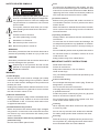
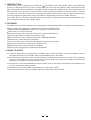
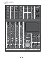
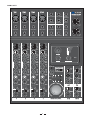
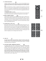
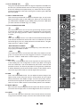
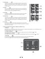
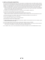
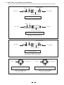
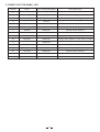
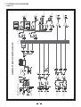
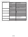
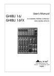
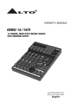
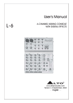
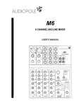
User's Manual
GHIBLI 16/
GHIBLI 16FX
16-CHANNEL MIXING
CONSOLE/WITH
DIGITAL EFFECTS
R
LTO
www.altoproaudio.com
Version 1.2 September 2006
English
Fuse
SAFETY RELATED SYMBOLS
CAUTION
RISK OF ELECTRIC SHOCK
DO NOT OPEN
This symbol, wherever used, alerts you to the presence of un-insulated and dangerous voltages within the product enclosure. These are voltages that
may be sufficient to constitute the risk of electric
shock or death.
Protective Ground
Before turning the product ON, make sure that it is
connected to Ground. This is to prevent the risk of
electric shock.
This symbol, wherever used, alerts you to important operating and maintenance instructions.
Please read.
Never cut internal or external Ground wires. Likewise,
never remove Ground wiring from the Protective
Ground Terminal.
Protective Ground Terminal
Operating Conditions
AC mains (Alternating Current)
Always install in accordance with the manufacturer's
instructions.
Hazardous Live Terminal
ON:
To prevent fire and damage to the product, use only
the recommended fuse type as indicated in this
manual. Do not short-circuit the fuse holder. Before
replacing the fuse, make sure that the product is
OFF and disconnected from the AC outlet.
To avoid the risk of electric shock and damage, do
not subject this product to any liquid/rain or moisture.
Do not use this product when in close proximity to
water.
Denotes the product is turned on.
OFF: Denotes the product is turned off.
WARNING
Describes precautions that should be observed to
prevent the possibility of death or injury to the user.
CAUTION
Do not install this product near any direct heat source.
Do not block areas of ventilation. Failure to do so
could result in fire.
Keep product away from naked flames.
Describes precautions that should be observed to
prevent damage to the product.
Disposing of this product should not be
placed in municipal waste and should be
Separate collection.
IMPORTANT SAFETY INSTRUCTIONS
Read these instructions
Follow all instructions
Keep these instructions. Do not discard.
Heed all warnings.
WARNING
Only use attachments/accessories specified by the
manufacturer.
Power Supply
Ensure that the mains source voltage (AC outlet)
matches the voltage rating of the product. Failure
to do so could result in damage to the product and
possibly the user.
Power Cord and Plug
Do not tamper with the power cord or plug. These are
designed for your safety.
Unplug the product before electrical storms occur
and when unused for long periods of time to reduce
the risk of electric shock or fire.
Do not remove Ground connections!
External Connection
Protect the power cord and plug from any physical
stress to avoid risk of electric shock.
Always use proper ready-made insulated mains
cabling (power cord). Failure to do so could result
in shock/death or fire. If in doubt, seek advice from
a registered electrician.
Do Not Remove Any Covers
Within the product are areas where high voltages
may present. To reduce the risk of electric shock do
not remove any covers unless the AC mains power
cord is removed.
Covers should be removed by qualified service
personnel only.
No user serviceable parts inside.
1
If the plug does not fit your AC outlet seek advice from
a qualified electrician.
Do not place heavy objects on the power cord. This
could cause electric shock or fire.
Cleaning
When required, either blow off dust from the product
or use a dry cloth.
Do not use any solvents such as Benzol or Alcohol.
For safety, keep product clean and free from dust.
Servicing
Refer all servicing to qualified service personnel only.
Do not perform any servicing other than those instructions contained within the User's Manual.
TABLE OF CONTENTS
1. INTRODUCTION...........................................................................................................................................3
2. FEATURES...................................................................................................................................................3
3. READY TO START.......................................................................................................................................3
4. CONTROL ELEMENTS...............................................................................................................................4
5. INSTALLATION AND CONNECTION........................................................................................................10
6. PRESET LIST.............................................................................................................................................13
7. SYSTEM BLOCK DIAGRAMS...................................................................................................................14
8. TECHNICAL SPECIFICATION...................................................................................................................16
9. WARRANTY................................................................................................................................................17
2
1. INTRODUCTION
Thank you very much for expressing your confidence in LTO products by purchasing GHIBLI 16(FX) 16-Channel Mixing
Console. You will get the smooth, accurate more natural and open sound from this apparatus, and it is really ideal for small
gigs, recording and fixed PA installations. The GHIBLI 16(FX) is packed with features that can not be found in other con
soles of its size: 4 mono (these are provided with ultra low noise microphone preamplifiers and Phantom Power at +18 Volt)
and 4 stereo input channels, and each mono channel with 3 bands EQ + Mid Frequency sweep and MUTE function; highly
accurate 4-segment bar graph meters; built-in high efficiency digital effects processor for GHIBLI 16FX only;
Your GHIBLI 16(FX) is very easy to operate but we advise you to go through each section of this manual carefully. In this
way you will get the best out of your GHIBLI 16(FX).
2. FEATURES
The GHIBLI 16(FX) 16-Channel Mixing Console is designed for professional application. It provides the following features:
Mono channels with 3 bands EQ + Mid Frequency sweep and MUTE function.
TUBE SOUND COMPRESSOR on the MIC1-4 channels + De-esser function.
Insert function for all mono channels.
Surround processor with center and surround out + Stereo Bass Enhancer.
Extremely high headroom offering more dynamic range
Balanced ultra low noise microphone inputs with "HIGH END PREAMP"
Suitable for live, studio and home applications
2 AUX Control per mono channel for internal/external effects and monitoring
High-quality, low tolerance components for highest results.
Rugged construction ensures long life and durability
External power supply design for professional applications.
3. READY TO START
3.1 There is a small black box provided with your GHIBLI 16(FX). This is the specific 18V AC input adapter. Connect
the proper terminal into your GHIBLI 16(FX) and the adapter into an AC socket.
3.2 Be sure that the main power switch is turned off before connecting the mixer to the AC socket. Also, You should
make sure that all input and output controls are turned down before connecting the AC adapter. This will avoid
damage to your speakers and avoid excessive noise.
3.3 You shall turn on the mixer BEFORE the power amplifier and turn the mixer off AFTER the power amplifier once
you have finished your working session.
3.4 Before disconnecting the GHIBLI 16(FX) always turn off the power switch.
3.5 Do not use solvents to clean your GHIBLI 16(FX). A dry and clean cloth will be OK.
3
4. CONTROL ELEMENTS
GHIBLI 16
MIC 1
MIC 3
MIC 2
MIC 4
R
LTO
GHIBLI 16
16-CHANNEL MIXING CONSOLE
2
1
2
1
2
1
2
CENTER &
CH5 LEFT IN (MONO) CH7 LEFT IN (MONO)
SURROUND OUT
1
3
3
3
3
MIC IN (BAL)
MIC IN (BAL)
MIC IN (BAL)
MIC IN (BAL)
CH6 RIGHT IN
CH8 RIGHT IN
AUX1 OUT
LINE IN (UNBAL)
LINE IN (UNBAL)
LINE IN (UNBAL)
LINE IN (UNBAL)
CH9-10 IN (LEFT)
CH13-14 IN (LEFT)
AUX2 OUT
INSERT
INSERT
INSERT
INSERT
CH12-11 IN (RIGHT)
CH16-15 IN (RIGHT)
PHONES
LOW CUT
HARD
100Hz
OFF
LOW CUT
HARD
100Hz
OFF
LOW CUT
HARD
100Hz
OFF
SOFT
SOFT
BYPASS COMP DE-ES
BYPASS COMP DE-ES
BYPASS COMP DE-ES
BYPASS COMP DE-ES
CLIP
MIC 0
LINE -20
50 0dB
+30
0dB
15KHz
HIGH
-15
+15
0dB
-15
50 0dB
+30
0dB
15KHz
-15
+15
+15
+15
+15
+15
freq
Hz
+15
0dB
-15
1KHz
MID
HIGH
MID
-15
1KHz
50 0dB
+30
0dB
15KHz
-15
0dB
MID
-15
CLIP
MIC 0
LINE -20
HIGH
-15
0dB
MID
50 0dB
+30
0dB
15KHz
MID
+15
1KHz
MID
freq
Hz
RIGHT
OUT
GAIN
CLIP
MIC 0
LINE -20
HIGH
MID
1KHz
GAIN
CLIP
MIC 0
LINE -20
BALANCED +4dBu
LOW CUT
SOFT
GAIN
LEFT
OUT
HARD
100Hz
OFF
SOFT
GAIN
BALANCED +4dBu
MID
freq
Hz
freq
Hz
OPERATING
BASS ENHANCER
LOW
80Hz
80Hz
BYPASS
ON
-
0dB
-
+10
PAN
8
0dB
-
+10
PAN
8
-20
AUX2
post
+10
center
-10
0
10
0dB
+10
1
-
-
+10
2
CH
ON
MUTE
LEVEL
0dB
-
+10
3
Left
0dB
-
MUTE
LEVEL
-
-
MAIN MIX LEVEL
4
-
LEVEL
+10
7-8
0dB
AUX1
pre
-
+10
0dB
+10
4
0dB
5-6
PAN
Right
CH
ON
PAN
Right
Left
LEVEL
+10
8
MUTE
LEVEL
0dB
Right
+10
center
RIGHT
8
8
-
CH
ON
Left
8
MUTE
LEVEL
0dB
Right
8
CH
ON
Left
8
Right
PAN
Right
Left
0dB
Left
-
+10
center
AUX1
pre
LEFT
+10
AUX2
post
center
AUX1
pre
+10
PHONES
8
8
AUX1
pre
-
-
+15
0dB
+10
AUX2
post
center
PAN
-
-15
8
-
+10
center
AUX1
pre
0dB
AUX2
post
+15
0dB
+10
8
-
-15
8
AUX1
pre
0dB
-
+15
0dB
+10
8
-
-15
8
+15
0dB
8
-15
0dB
AUX1
pre
0dB
8
LOW
80Hz
0dB
0dB
8
LOW
80Hz
5K
600
0dB
0dB
LEVEL
+10
9-12
-
AUX1
pre
+10
8
LOW
5K
600
0dB
8
5K
600
0dB
8
5K
600
LEVEL
+10
13-16
GHIBLI 16FX
MIC 1
MIC 3
MIC 2
MIC 4
R
LTO
GHIBLI 16 FX
16-CHANNEL MIXING CONSOLE
2
1
2
1
2
1
2
1
3
3
3
3
MIC IN (BAL)
MIC IN (BAL)
MIC IN (BAL)
MIC IN (BAL)
CH6 RIGHT IN
CH8 RIGHT IN
LINE IN (UNBAL)
LINE IN (UNBAL)
LINE IN (UNBAL)
CH9-10 IN (LEFT)
CH13-14 IN (LEFT)
AUX2 OUT
INSERT
INSERT
INSERT
INSERT
CH12-11 IN (RIGHT)
CH16-15 IN (RIGHT)
PHONES
LOW CUT
HARD
100Hz
LOW CUT
HARD
100Hz
OFF
LOW CUT
HARD
100Hz
OFF
SOFT
SOFT
SOFT
BYPASS COMP DE-ES
BYPASS COMP DE-ES
BYPASS COMP DE-ES
GAIN
GAIN
GAIN
GAIN
CLIP
CLIP
CLIP
CLIP
MIC 0
LINE -20
50 0dB
+30
0dB
HIGH
15KHz
MIC 0
LINE -20
50 0dB
+30
0dB
HIGH
15KHz
LEFT
OUT
BALANCED +4dBu
RIGHT
OUT
LOW CUT
SOFT
50 0dB
+30
0dB
HIGH
15KHz
BALANCED +4dBu
HARD
100Hz
OFF
BYPASS COMP DE-ES
MIC 0
LINE -20
DIGITAL EFFECTS
AUX1 OUT
LINE IN (UNBAL)
OFF
WITH
CENTER &
CH5 LEFT IN (MONO) CH7 LEFT IN (MONO)
SURROUND OUT
MIC 0
LINE -20
15
14
13
12
11
50 0dB
+30
0dB
HIGH
15KHz
16 1
2
4
5
6
10 9 8
PRESETS
VIBRAFLANGE
FUNKY
ROCKABILLY
BIGSTAGE
VIBRATO
1
2
3
4
5
8
9
12
13
16
3
7
FLANGER
CHORUS
PEAK
0dB
-15
-15
+15
0dB
MID
+15
1KHz
-15
+15
0dB
+15
-15
1KHz
MID
+15
MID
-15
1KHz
freq
Hz
-15
0dB
MID
-15
MID
+15
MID
+10
REVERB LEVEL
+10
FX LEVEL
+15
1KHz
MID
freq
Hz
-
8
+15
8
-15
MID
freq
Hz
freq
Hz
OPERATING
BASS ENHANCER
0dB
LOW
0dB
0dB
LOW
80Hz
LOW
80Hz
80Hz
BYPASS
ON
-
0dB
AUX2
post D
F
D
F
X
center
PAN
AUX1
pre
8
+10
AUX2
post D
F
-20
AUX2
post
-10
0
10
Right
Left
0dB
PAN
-
+10
center
PAN
+10
center
+10
1
-
+10
-
+10
2
Right
0dB
Right
CH
ON
MUTE
LEVEL
0dB
-
+10
3
Left
LEVEL
0dB
-
MUTE
LEVEL
-
7-8
-
+10
4
5
MAIN MIX LEVEL
-
+10
0dB
+10
0dB
AUX1
pre
Right
CH
ON
-
5-6
PAN
8
MUTE
LEVEL
0dB
PAN
RIGHT
8
8
-
CH
ON
Left
8
MUTE
LEVEL
0dB
Right
8
CH
ON
Left
8
Right
+10
center
Left
LEVEL
0dB
Left
PAN
LEFT
+10
0dB
-
+10
center
PHONES
AUX1
pre
X
-
+10
8
8
0dB
X
-
+10
center
-
+10
AUX2
post D
F
X
-
-
+10
-
+15
0dB
AUX1
pre
8
0dB
AUX1
pre
-15
8
-
+15
0dB
8
AUX1
pre
-15
8
+15
0dB
+10
8
-
-15
8
+15
0dB
8
-15
0dB
AUX1
pre
8
80Hz
0dB
0dB
LEVEL
+10
9-12
-
AUX1
pre
+10
8
0dB
LOW
5K
600
8
0dB
5K
600
8
5K
600
8
5K
600
LEVEL
+10
13-16
4.1 THE MIC/LINE INPUT
1
These are Channel 1 through Channel 4. You can connect balanced, low
impedance microphones or a low level signal to the XLR socket. On the
1/4" Line jack you can connect either a microphone or a line level instrument .
Note: You shall never connect an unbalanced microphone to the XLR
socket if you do not want to damage both the microphone and the mixer.
Also, it is not possible to simultaneously use both the MIC&LINE inputs
on the same channel, use only one of them for the appropriate source on
each channel.
MIC 1
2
1
MIC IN (BAL)
- PHANTOM POWER +18 Volts
It is available only on the XLR input sockets. Please make sure the power
switch is turned off before connecting a microphone to the XLR input.
4.2 MONO CHANNEL INSERT
LINE IN (UNBAL)
2
2
Insert points are provided for mono MIC channels, which can allow you to
patch external signal processing devices into signal path. When you insert
a TRS jack in the insert socket, the signal will be taken out after the channel
compressor, sent to an external processor, and returned into the channel
strip immediately before the EQ section. Of course, the jacks used must be
stereo (Tip Send/Ring Return).
4.3 STEREO INPUT (CH5~CH16)
INSERT
3
Each stereo channel comes with two unbalanced line level inputs on 1/4"
TRS jacks, which are used to connect left and right input signals. Use the
LEFT input when connect a mono input signal to the STEREO INPUT. The
last two stereo channels feature an original and exclusive double stereo
input for each stereo channel. This feature allows you to connect two stereo
sources at the same time for each stereo channel, enlarging the real
number of signals you can manage at the same time.
4.4 LOW CUT
1
3
4
By pushing this switch you will activate a 100Hz low frequency filter that
provides a precise cut for frequencies under 100Hz. You can use this facility
to reduce the hum noise infected by the mains power supply, or the stage
rumble while using a microphone.
4.5 THE TUBE SOUND COMPRESSOR SWITCH
5
The TSC switch (on the first 4 channels) activates the TUBE SOUND
COMPRESSOR and let you choose between Compressor and De-esser
functions. The two yellow LEDs show the amount of compression applied
to the input signal. Two algorithms are provided, one for soft compression
with a threshold level of 0dB, and one for hard limiting with a threshold
level of around +10dB. This dynamic processor works on the very entry
stage of the channel and it can avoid also the channel clipping, maintain
the best signal-to-noise ratio. The compression algorithm applied to the
sound is shown by two yellow LEDs.
6
CH5 LEFT IN (MONO) CH7 LEFT IN (MONO)
CH6 RIGHT IN
CH8 RIGHT IN
CH9-10 IN (LEFT)
CH13-14 IN (LEFT)
CH12-11 IN (RIGHT)
CH16-15 IN (RIGHT)
3
6
4.6 CLIP LED/0dB LED
The green LED illuminates when the signal overpasses the 0dB level,
the red CLIP LED illuminates when the channel is going into overload.
If the CLIP LED becomes permanently on, reduce the amount of gain.
To have best signal-to-noise ratio set the gain so that the green 0dB LED
becomes lighted.
7
4.7 INPUT LEVEL SETTING
LOW CUT
This control is provided with 2 different indication rings: one is for the
MIC input and the other for the LINE input. When you use a MIC input
you shall read the INSIDE ring (0~50dB); when you use a LINE input
you shall read the OUTSIDE ring (-20~+30dB).
100Hz
OFF
SOFT
GAIN
CLIP
MIC 0
LINE -20
50 0dB
+30
0dB
HIGH
15KHz
-15
MID
9
-15
+15
1KHz
MID
freq
Hz
- LOW
11
This is the bass control. It is used to boost male voice, kickdrum or bass
guitar. Your system will sound much bigger than what it is. The gain range
goes from -15dB to +15dB and the center frequency is 80Hz.
LOW
80Hz
11
-15
+15
0dB
+10
8
-
AUX1
pre
0dB
D
F
X
+10
8
-
12
AUX2
post
center
PAN
13
13
14
Left
15
This control will adjust the overall level of this channel and set the amount
of signal sent to the Main output, and to the Surround and Center outputs.
7
MUTE
LEVEL
0dB
14
15
-
Mono channels are provided with a MUTE switch that allows to switch on
and off the channel signal, both on Left and Right buses and on AUX ones.
Right
CH
ON
8
This is the PANORAMA control. You can adjust the stereo image of the
signal via this control. Keep this control in center position and your signal
will be positioned in the middle of stage. Turn this control fully counterclockwise and the signal will be present only on the left speaker and viceversa. Of course a wide number of intermediate positions are available.
4.12 LEVEL
10
5K
600
0dB
4.11 MUTE SWITCH
7
+15
0dB
- MID FREQUENCY SWEEP
10
This control allow to choose the ceuter frequency of the mid band in a
range going from 600Hz to 5KHz.
4.10 PAN
6
8
- MID
9
This is the midrange control. It can affect most fundamental frequencies
of all musical instruments and human voice. An attentive use of this
control will give you a very wide panorama of sound effects. The gain
range goes from -15dB to +15dB.
4.9 AUX 1& 2
12
This control is used to adjust the level of respective channel signal sent
to the Auxiliary Bus. The configuration of AUX1 is pre-fader so the signal
sent to the AUX Bus 1 will not be affected by the LEVEL control of that
particular channel. The AUX2 is post-fader so the signal sent to AUX Bus
2 will be affected by the channel LEVEL control. In this GHIBLI 16FX,
The AUX2 signal also feeds the internal digital effect processor.
5
BYPASS COMP DE-ES
4.8 The 3 BANDS EQUALISER
- HI
8
This is the treble control. You can use it to get rid of high frequency noises
or to boost the sound of cymbals or the high harmonics of the human
voice. The gain range goes from -15dB to +15dB with a center frequency
of 15kHz.
4
HARD
+10
1
4.13 AUX1 pre
16
-
4.14 PAN
8
0dB
17
0dB
AUX1
pre
-
+10
center
8
The AUX1 control allows to manage the signals coming from the
stereo inputs and send them to AUX1 output in order to feed the
monitors. The level of this signal is not affected by the channel
LEVEL control.
PAN
AUX1
pre
+10
center
16
PAN
17
This control allows to choose the position of a mono input signal into
the stereo field. It allows also to modify the amount of left and right
level for a stereo input signal (balance function).
Right
Left
0dB
Right
Left
0dB
LEVEL
LEVEL
18
-
0dB
4.17 LEVEL
-
+10
0dB
The AUX1 control allows to manage the signals coming from the
stereo inputs and send them to AUX1 output in order to feed the
monitors. The level of this signal is not affected by the channel
LEVEL control.
0dB
AUX1
pre
0dB
LEVEL
AUX1
pre
19
+10
8
-
8
19
+10
7-8
5-6
It determines the amount of the input signal on the main mix (LEFT
and RIGHT output) and on the Surround and Center outputs.
LEVEL
20
-
+10
8
-
+10
8
4.16 AUX1 pre
-
+10
8
18
8
4.15 LEVEL
13-16
9-12
20
It is channel's LEVEL control and it determines the amount of the
input signals on the main mix (LEFT and RIGHT output) and on the Surround and Center outputs.
4.18 24 BIT DIGITAL EFFECTS (For GHIBLI 16FX Model only)
- PRESETS
21
Adjust this knob to select the right effect you wish to perform. There are total 16 options for you: Vibraflange, Funky,
Rockabilly, Bigstage, Vibrato, Flanger and Chorus etc.
- FX LEVEL CONTROL
22
This control is used to adjust the output level of FX signal, which can be varied from -
to 10dB.
- REVERB LEVEL CONTROL
23
This control is used to adjust the output level of REVERB signal, which can be varied form -
to 10dB.
- PEAK LED
24
This LED will illuminate when the internal effect signal is too high and possibly distorted.
In case of the digital effect module being muted, this LED also lights up.
21
15
14
13
12
11
16 1
2
3
4
5
6
10 9 8
PRESETS
7
1
2
3
4
5
8
9
12
13
16
VIBRAFLANGE
FUNKY
ROCKABILLY
BIGSTAGE
VIBRATO
FLANGER
CHORUS
22
+10
FX LEVEL
+10
REVERB LEVEL
8
8
PEAK
-
24
8
24
25
4.19 OPERATING LED
The operating LED, when is on, shows that the main power
supply is present and the mixer is operating.
25
OPERATING
BASS ENHANCER
26
28
0dB
BYPASS
This control sets the amount of signal sent to the PHONES
output.
-
ON
26
+10
8
4.20 PHONES
PHONES
27
4.21 VU METER
LEFT
-20
It is the output VU meter of the mixer, it shows both the left
and right output signal level.
-10
0
27
10
RIGHT
28
4.22 BASS ENHANCER
This is the BASS ENHANCER processor switch. Inserting this
processor it is possible to increase and optimize the general performance at low frequency of the mixer.
29
29
4.23 MAIN MIX LEVEL
This control sets the amount of signal sent to the MAIN MIX
LEFT and RIGHT outputs.
MAIN MIX LEVEL
4.24 CENTER & SURROUND OUT
30
This is Center and Surround output of the mixer. You can pick
up their signals using an insert cable.
31
4.25 AUX1 OUT
This is the AUX1 output, it is useful to connect active monitors
to the mixer.
30
32
4.26 AUX2 OUT
GHIBLI 16 FX
16-CHANNEL MIXING CONSOLE
This is the AUX2 output, using its signal it is possible to feed
an external effect processors, wiring the effect return to one
of the stereo channels of the mixer.
4.27 PHONES
R
LTO
WITH
CENTER &
SURROUND OUT
DIGITAL EFFECTS
31
AUX1 OUT
33
This socket will be used to send the signal to a pair of headphones as well as active monitors.
32
BALANCED +4dBu
LEFT
OUT
BALANCED +4dBu
RIGHT
OUT
AUX2 OUT
4.28 MAIN MIX OUTPUT
34
This stereo output is controlled by the MAIN MIX LEVEL on
the front panel and will send the audio signal to an external
amplifier. It is electronically balanced and it has got a professional standard level of +4dBu. You can use both for stereo
and for surround system wiring.
33
PHONES
4.29 REAR PANEL
- POWER SUPPLY
35
Used to connect the supplied 24V AC adapter, supplied by
LTO company only.
- POWER ON/OFF SWITCH
36
This switch is used to turn the main power ON and OFF.
36 35
MODEL
SERIAL
POWER POWER
ON SUPPLY
9
34
5. INSTALLATION AND CONNECTION
Ok, you have got to this point and you are now in the position to successfully operate your GHIBLI 16(FX). However,
we advise you to read carefully the following section to be the real master of your own mixer. Not paying enough
attention to the input signal level, to the routing of the signal and the assignment of the signal will result in unwanted
distortion, a corrupted signal or no sound at all. So you should follow these procedures for every single channel:
1). Before connecting mics or instruments, make sure that the power of all your systems components including the
mixer is turned off. Also, make sure that all input and output controls of your mixer are turned down. This will avoid
damage to your speakers and avoid excessive noise.
2). Properly connect all external devices such as microphone, power amplifier, speakers etc.
3). Connect the 24V AC adapter to the mixer and main power.
4). Now, turn on the power of any perpheral devices, and then power up the mixer.
Note: the power amplifier or powered monitors shall be turned on after the mixer and turned off before the mixer.
5). Set the output level of your GHIBLI 16(FX) or the connected power amplifier at no more than 75%.
6). Now, set the PHONE level at no more than 50%.
7). Set HI, MID and LOW EQ controls on the middle position
8). Set panoramic controls on the middle position.
9). While speaking into the mic (or playing the instrument), adjust the channel level control so to maintain a good
headroom and ideal dynamic range.
10). You can shape the tone of each channel by adjusting the equalizer controls as desired.
11). Now repeat the same sequence for all other input channels. The Main LED Meter could move up into the red section.
In this case you can adjust the overall output level through the MAIN MIX control.
12). For GHIBLI 16FX, you can select desired DSP sound effects via PRESET and FX & REVERB LEVEL controls.
10
5.1 SOME FINAL TIPS ON WIRING CONFIGURATION
You can connect unbalanced equipment to balanced inputs and outputs. Simply follow these schemes.
Ring=Right Signal
Tip
Sleeve
Ring
Strain Clamp
Tip=Left Signal
Sleeve=Ground/Screen
Use for Headphone
1/4" Stereo (TRS) Jack Plug
Sleeve
Tip
Tip=Signal
Strain Clamp
Sleeve=Ground/Screen
Use for Mono Line In, Mono 1/4"Jack Plugs
1/4" Mono (TS) Jack Plug
Sleeve
Ring=Return Signal
Tip
Ring
Strain Clamp
Tip=Send Signal
Sleeve=Ground/Screen
Use for Insert Points
1/4" Stereo (TRS) Jack Plug
2=Hot(+)
2
1
3
2=Hot(+)
1=Ground/Screen
3=Cold(-)
2
1
3
1=Ground/Screen
3=Cold(-)
Use for Balanced Mic Inputs
(For unbalanced use, connect pin 1 to 3)
Use for Main output
(For unbalanced use, leave pin 3 unconnected)
3-pin XLR Male Plug
3-pin XLR Line Socket
(seen from soldering side)
(seen from soldering side)
11
Ring=Return Signal (Connected together)
To Channel Insert
Sleeve=Ground/Screen
Tip=Signal
To Tape or FX Input
Sleeve=Ground/Screen
'Tapped' Connection Direct Output Lead
(Enables the Insert to be used as a Direct Output
while maintaining the channel signal flow)
To Processor Input
Sleeve=Ground/Screen
Tip=Send Signal
Tip
To Channel Insert
Sleeve
Ring=Return Signal
Ring
To Processor Output
-Stereo lead for insert Connection
(To be used when the processor does not employ a
single jack connection for the In/Out Connections)
12
6. PRESET LIST FOR GHIBLI 16FX
Position
Name
Eff.1 Variat (REVERB)
Eff.2 Variat (FX)
1
Vibraflange
Spring Rev.
Waves
2
Funky
Spring Rev.
Funky style
3
Rockabilly
Tape Rev.
Slow & Soft Flanger
4
Bigstage
Hall Rev.
Solo Flanging
5
Vibrato4
Base Rev.
Vibrato modul. Speed 4
6
Vibrato3
Base Rev.
Vibrato modul. Speed 3
7
Vibrato2
Base Rev.
Vibrato modul. Speed 2
8
Vibrato1
Base Rev.
Vibrato modul. Speed 1
9
Flanger4
Base Rev.
Flanger modul. Speed 3 + mod. Depth + Feedbk
10
Flanger3
Base Rev.
Flanger modul. Speed 4 + mod. Depth + Feedbk
11
Flanger2
Base Rev.
Flanger modul. Speed 2
12
Flanger1
Base Rev.
Flanger modul. Speed 1
13
Chorus4
Base Rev.
Chorus modul. Speed 4
14
Chorus3
Base Rev.
Chorus modul. Speed 3
15
Chorus2
Base Rev.
Chorus modul. Speed 2 + mod. Depth
16
Chorus1
Base Rev.
Chorus modul. Speed 1
13
14
A
B
C
D
2
3
1
1
CH11/CH15 (RIGHT)
CH12/CH16 ( LEFT)
CH10/CH14 (RIGHT)
CH9/CH13 (LEFT)
CH6/CH8(RIGHT)
CH5/CH7(MONO)
X2
X1
MIC GAIN: 0~50dB
LINEGAIN: +30dB~-20dB
LINE IN
MIC IN
PHANTOM
POWER
+18V
1a
2b
4d
3c
5e
1a
2b
4d
3c
5e
1a
2b
4d
3c
5e
1a
2b
4d
3c
5e
MONO INPUT CHANNELS(1-4)
1
2
2
LOW CUT 100HZ
LOW CUTSW
LOW CUT SW
LOW CUT 100HZ
GAIN
4
5
LEVEL
AUX1PRE
3
INSERT
T
R
RN
TN
R BUS
L BUS
AUX1PRE
PAN
5e S
3c
4d
2b
1a
SOFTDE-ES
COMP
BYPASS
R BUS
L BUS
MID (FREQ) HI
+/-15db
4
80 600Hz-5KHz 15K
3-BAND EQ
LO
MUTE
PRE
AUX1
POST
AUX2
LEVEL
5
PAN
GHIBLI 16 BLOCK DIAGRAM
3
AUX-2
6
MASTER LEVEL
MASTER LEVEL
6
LEFT-BUS
BASS ENAHANCER
BASS ENAHANCER
PHONES LEVEL
PHONES LEVEL
D9
D7
D9
D7
7
-10dB
RED
10dB
GR
-10dB
RED
10dB
GR
7
D8
D6
D8
D6
0dB
GR
-20dB
YEL
0dB
GR
-20dB
YEL
8
AUX2(POST)
AUX1(PRE)
HEADPHONE OUTPUT
CENTER&SURROUNDOUT
MAIN RIGHT OUTPUT
2
3
1
MAIN LEFT OUTPUT
2
3
1
8
A
B
C
D
7. SYSTEM BLOCK DIAGRAMS
GHIBLI 16
AUX-1
RIGHT-BUS
8. TECHNICAL SPECIFICATION
Mono input channels
Microphone input
electronically balanced
Bandwidth
Distortion (THD & N)
15Hz to 20kHz, +/3dB
Gain range
SNR (Signal to Noise Ratio)
Line input
Stereo input channels
Bandwidth
Distortion (THD & N)
Line level range
Max input level
Line input
Equalization
unbalanced
15Hz to 60kHz, +/3dB
0.007% at +4dBu, 1kHz, Bandwidth 60KHz
-20dBu to +30dBu
+10dBu
Bandwidth
Distortion (THD & N)
unbalanced
10Hz to 55kHz, +/3dB
0.007% at +4dBu, 1kHz, Bandwidth 80KHz
Hi shelving
+
15dB @12kHz
+
15dB @600~5kHz
Mid bell
Low shelving
Max output
Main Mix Section
AUX Sends max out
Phones Out
Center, Surround output
Signal-to-Noise Ratio
Power Supply (AC/AC Adapter) Main voltage
Physical
0.007% at +4dBu, 1kHz, Bandwidth 20KHz
0dB to 50dB (MIC)
Dimension (W D H)
Net weight
Shipping weight
16
+ 15dB @80Hz
+26dBu balanced
+22dBu unbalanced
+22dBu unbalanced
+22dBu unbalanced
112dB, all channels at Unity Gain
USA/Canada ~115VAC, 60Hz;
Europe ~230VAC, 50Hz;
U.K./Australia ~240VAC, 50Hz
Japan ~100VAC, 60Hz
270mm 198mm 43mm
1.73Kg
2.45Kg
9. WARRANTY
10.1 WARRANTY REGISTRATION CARD
To obtain Warranty Service, the buyer should first fill out and return the enclosed Warranty Registration Card
within10 days of the Purchase Date.
All the information presented in this Warranty Registration Card gives the manufacturer a better understanding
of the sales status, so as to purport a more effective and efficient after-sales warranty service.
Please fill out all the information carefully and genuinely, miswriting or absence of this card will void your warranty
service.
10.2 RETURN NOTICE
a. In case of return for any warranty service, please make sure that the product is well packed in its original shipping
carton, and it can protect your unit from any other extra damage.
b. Please provide a copy of your sales receipt or other proof of purchase with the returned machine, and give detail
information about your return address and contact telephone number.
c. A brief description of the defect will be appreciated.
d. Please prepay all the costs involved in the return shipping, handling and insurance.
10.3 TERMS AND CONDITIONS
a.
LTO warrants that this product will be free from any defects in materials and/or workmanship for a period
of 1 year from the purchase date if you have completed the Warranty Registration Card in time.
b. The warranty service is only available to the original consumer, who purchased this product directly from the
retail dealer, and it can not be transferred.
c. During the warranty service, LTO may repair or replace this product at its own option at no charge to you for
parts or for labor in accordance with the right side of this limited warranty.
d. This warranty does not apply to the damages to this product that occurred as the following conditions:
Instead of operating in accordance with the user's manual thoroughly, any abuse or misuse of this product.
Normal tear and wear.
The product has been altered or modified in any way.
Damage which may have been caused either directly or indirectly by another product / force / etc.
Abnormal service or repairing by anyone other than the qualified personnel or technician.
And in such cases, all the expenses will be charged to the buyer.
e. In no event shall LTO be liable for any incidental or consequential damages. Some states do not allow the exclusion or limitation of incidental or consequential damages, so the above exclusion or limitation may not apply to you.
f. This warranty gives you the specific rights, and these rights are compatible with the state laws, you may also
have other statutory rights that may vary from state to state.
17
SEIKAKU TECHNICAL GROUP LIMITED
No. 1, Lane 17, Sec. 2, Han Shi West Road, Taichung 40151, Taiwan
http://www.altoproaudio.com Tel: 886-4-22313737
email: [email protected] Fax: 886-4-22346757
All rights reserved to ALTO. All features and content might be changed
without prior notice. Any photocopy, translation, or reproduction of part of this
manual without written permission is forbidden. Copyright c 2006 SEIKAKU GROUP
NF01889-1.2