1
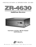
I N S TA L L AT I O N G U I D E
H O M E T H E AT E R M A I N S Y S T E M U N I T
HT-MSU
CONGRATULATIONS!
Thank you for purchasing the HT-MSU Home Theater Main System Unit from Niles. With proper
installation and operation, you should enjoy years of trouble-free use.
Niles manufactures the industry’s most complete line of custom installation components and
accessories for audio/video systems. To see the complete Niles product assortment, visit us on
the Internet at: www.nilesaudio.com
TABLE OF CONTENTS
Introduction
1
Features and Benefits
2
Contents
3
Parts Guide
4
System Design Considerations
5
Installation Considerations
11
Installation
14
Troubleshooting
17
Accessories
19
Specifications
21
Warranty
24
Warranty Registration Card
25
INTRODUCTION
Thank you for purchasing the Niles HT-MSU Home Theater Main System Unit. The HT-MSU
addresses an essential need of today’s consumers—the ability to easily control and manage the
assortment of entertainment sources found in the home theater environment.
Home theater systems are often controlled entirely by the remote. The result is a big, bulky, remote
control with small, complicated buttons or screens that only a “mad scientist” could figure out. The
Niles Home Theater Main System Unit (HT-MSU) ends the confusion by placing power and control
in an interface box and using the remote to “trigger” desired activities.
The Niles HT-MSU can be used with the Niles R-8 Handheld IR Remote Control or any learning
IR remote control programmed with Niles single-touch activity keys. With the Niles HT-MSU,
users gain levels of control that are simply not possible with traditional “universal” remotes.
Infrared, RS232, voltage triggers, and contact closures make the HT-MSU a complete control and
automation system for displays, surround receivers, cable boxes, satellite receivers, DVD players
and more. In addition, the HT-MSU can automate functions like lighting control, TV lifts, draperies,
and projection screens.
Home entertainment systems should be fun, not frustrating, and Niles has always recognized the
need for simple-to-use, cost-effective solutions. The Niles HT-MSU Home Theater Main System
Unit gives end users one-touch control of their home theater systems and reflects the high quality
fit and finish that meets the standards of today’s consumers.
NILES AUDIO CORPORATION – 1-800-BUY-HIFI – 305-238-4373
1
FEATURES AND BENEFITS
SIMPLE CONTROL OF COMPLEX SYSTEMS
The Niles HT-MSU Home Theater Main System Unit simplifies entertainment by allowing one-touch
control of home theater components. Ordinary home theater system controllers require users
to turn on (and off) multiple components, resulting in a confusing situation of hunting down the
fugitive component that is “off,” when it really should be “on.”
The HT-MSU eliminates the confusion by shifting control to an interface box. The remote initiates
commands to the HT-MSU, so whether you’re playing a DVD or watching a program recorded on
your DVR, the HT-MSU provides one-touch access to all your entertainment.
INTELLIGENT MAIN SYSTEM UNIT
The HT-MSU incorporates an infrared sensor port to control sources that use original remotes
or “all-in-one” programmable universal remotes, even if the system is hidden from view. The
HT-MSU has both video and 12 Volt sync inputs to manage the “power state” of your home theater
system components. These synch ports, along with IR flasher ports, RS232 control ports, and an
expansion port, allow the HT-MSU to control up to 22 devices from your home theater system and
even “share” sources with a house-wide distributed audio system. The HT-MSU also includes “dry
contact closure” relays and 12V trigger outputs that can be used to control devices like projector
lifts, screens, drapes or lighting. An ethernet expansion port is also included for system expansion,
communication to Niles MultiZone Receivers, and future upgrades.
INSTALLATION FLEXIBILITY
With a low profile design, easy-to-access connections, and rack-mount-hole wings, the HT-MSU
can be wall-mounted behind theater components or attached to the back of metal professional
racks.
QUICK AND EASY SET-UP WITH WIZARD-BASED NILES
QUICKCONFIG™ PC CONFIGURATION SOFTWARE
An HT-MSU configuration can be programmed, saved, and edited using the Niles QuickConfig PC
Configuration Software and Niles IR-CS Infrared Capture Station. The QuickConfig PC Configuration
Software is Wizard-based and guides the installer/programmer through basic and advanced
system designs.
ASSIGNABLE RELAYS AND 12V OUTPUTS
Three dry contact closures and three 12V DC trigger outputs can be independently programmed
to give installers greater control of mechanical devices or voltage-triggered power strips and
dispersion controlled home theater loudspeakers.
2
INTELLIGENT INTEGRATION WITH MULTI-ZONE SYSTEMS
The HT-MSU includes control ports that allow it to “share” sources with whole-house distributed
audio systems. The power state of these “shared” sources can be completely managed so that
sources are always powered-on when they need to be and powered-off when both whole-house
and home theater systems are turned off.
PROGRAM MEMORY PROTECTION
The entire system profile is stored in non-volatile memory within the HT-MSU. This safeguards
against accidental loss of the configuration programming.
CONTENTS
Check that your HT-MSU Home Theater Main System Unit contains the following:
• Home Theater Main System Unit (HT-MSU)
• HT-MSU Power Supply
• RF Antenna
• 10 ft. Antenna Extension Cable
• Antenna Wall Bracket
• System Configuration Worksheet
NILES AUDIO CORPORATION – 1-800-BUY-HIFI – 305-238-4373
3
PARTS GUIDE
THE HOME THEATER MAIN SYSTEM UNIT (HT-MSU)
7
1
10
9
8
2
3
13
4
5
6
11
12
Figure 1. HT-MSU Top View
1) IR Outputs - SRC1 – SRC6, TV/7, RCV/8 are eight dedicated 3.5mm jacks that output IR
data specifically for that source
2) RS232 Outputs - SRC1 – SRC6, TV/7 and RCV/8 are eight dedicated 3.5mm jacks that
output RS232 data specifically for that source
3) Assignable 12V Outputs - Three 3.5mm jacks, output 12V DC 150mA
when activated:
a. 12V outputs 1 & 2 are independent of each other and are programmable
to output 12V momentarily or constantly when activated.
b. 12V output 3 is assignable and outputs 12V constantly when active.
4) Assignable Relays - There are three, 3-position removable quick-connect plugs labeled
1, 2 and 3 for connecting either NO (normally open) or NC (normally closed) contact closure devices
to the HT-MSU.
4
5) IR Input - A 4-position removable quick-connect plug for connecting an IR sensor to the
HT-MSU. This connection allows IR control of the HT-MSU and/or IR pass-through for connected
sources
6) Global IR Output - A 3.5mm jack provides all IR codes that the HT-MSU generates
and all IR codes that come in through the IR Input connection and can be configured via Niles
QuickConfig Software for Normal or High output. Normal output is designed for a Niles MF1 IR
MicroFlasher®; high output is designed for a Niles IRB1 High-Output IR Flasher
7) RF Antenna Socket - The BNC connector accommodates the supplied antenna. The
antenna must be installed perpendicular to the ground for best results. A 10 ft. (3 meter) antenna
extension cable and mounting bracket are included if remote installation of the antenna is necessary.
The antenna is used when the HT-MSU is being controlled via a Niles compatible RF Remote
8) Status 12V or Video - Six video and voltage-sensing RCA synch inputs for sources
1 through 6 detect when a source is on/off for reliable system activation
9) Status 12V - Two voltage-sensing 3.5mm jacks for sources TV/7 and RCV/8 detect when
those sources are on/off for reliable system activation
10) Power 12V DC - A barrel connection for the provided 12V DC power supply
11) Diagnostic - A USB A connection for Niles Service Center
12) PC Connection/Expansion - A RJ45 connection used to plug in a computer for
system configuration programming or expanding the system design out to future Niles multizone
receivers. Niles QuickConfig PC Configuration Software is used for system configuration
13) RF Test - A 3.5mm jack used to connect the optional Niles IR/RF tester for testing RF reception
SYSTEM DESIGN CONSIDERATIONS
The Niles HT-MSU Home Theater Main System Unit is a highly flexible tool that allows system
designers to create home theater systems that will delight their customers. The following section
explains just some of the system design features of the Niles HT-MSU Home Theater Main System
Unit. To fully understand the system configurations, it’s important to understand the basic control
sections of the HT-MSU.
IR INPUT PORT
This connection is used to control the HT-MSU and all of the home theater sources connected to
it. Each of the system configurations that follow must include an Infrared Sensor connected to this
port and a learning remote programmed with the Niles HT-MSU codes or the Niles R-8 Remote
control. This port also allows for IR pass-through of IR codes from the original remotes of the
connected sources. (Refer to the Accessories section on page 19 for more information on Niles IR
sensors.)
NILES AUDIO CORPORATION – 1-800-BUY-HIFI – 305-238-4373
5
IR OUTPUT PORTS
IR (Infrared) codes are stored in the HT-MSU during configuration programming. The labels of the
IR Outputs identify what source number these ports are designed to operate. SRC1 means source
1. The outputs are labeled SRC1 through SRC6, TV/7 and RCV/8. If the TV is to be controlled via
IR codes, then the IR Output TV/7 port should be used. However, if the TV will be controlled via
RS232, then the TV/7 IR output can be used to control an alternate IR source. These IR outputs are
dedicated and routed, meaning IR codes stored for source number 3 (i.e., a DVD player) can only
be emitted from the IR output port labeled SRC3. RCV/8 can be used either for the receiver in the
home theater or a source number 8.
RS232 OUTPUT PORTS
RS232 is a serial device control protocol that allows sources to be controlled via a transmit-receive
cable. (See the Installation section for wiring information.) RS232 codes are stored in the HT-MSU
as string codes during configuration programming. The labels of the RS232 Outputs identify what
source number they are designed to operate. SRC1 means source 1. The outputs are labeled SRC1
through SRC6, TV/7 and RCV/8. If the TV is to be controlled via RS232 codes, then the RS232 TV/7
port should be used. However, if the TV will be controlled via IR, then the RS232 TV/7 port can
be used to control an alternate RS232 source. These RS232 outputs are dedicated and routed,
meaning RS232 codes stored for source number 3 (i.e., a DVD player) can only be emitted from|
the RS232 output port labeled SRC3. RCV/8 can be used either for the receiver in the home theater
or a source number 8.
SOURCE POWER STATUS CONNECTIONS
To properly automate home theater sources, the HT-MSU needs to “know” when the source is
powered On or Off. There are three ways that sources are powered on:
1. Toggle Power: A source via its remote control has one button for turning that source
On and Off. When trying to automate such a device, you must provide the HT-MSU the
“Power Status” as feedback using the Status connection on the HT-MSU’s top edge
(detailed below).
2. Separate On and Off Power: A source via its remote control has one button to turn
the source On and a different button to turn the source Off. When trying to automate
such an IR device, you should provide the HT-MSU the “Power Status” as feedback so
the IC2 System will act faster using the Status connection on the HT-MSU. If a source
is to be controlled via RS232 and it has separate On and Off codes, you do not need to
provide the HT-MSU feedback.
3. Latching Power: Latching power is an industry term that means the source has no
power command/s on its remote control. A latching power source may have a “hard”
power button on the front panel. To determine if a source is latching power, push its
“hard” power button in, take its power cord and plug it into a live AC power outlet. If
it turns on when plugged into the outlet and turns off when unplugged from the outlet,
it is a latching power source. Latching power sources do not need a Power Status
6
connection, but you will want to do one of two things:
a. Plug it into the switched outlet of the receiver, or
b. Use a Niles AC-3 Voltage Triggered Power Strip connected to one of
the assignable 12V outputs on the HT-MSU. Use the QuickConfig PC
Configuration Software to program the assigned 12V output to turn on
when that source is selected. (See QuickConfig manual for more details on
programming 12V outputs.)
Along the top edge of the HT-MSU are the source-specific status connections labeled
SRC1 through SRC6. These RCA jacks are designed to sense either 12 Volts or video
so the HT-MSU “knows” when the source is On or Off. You must use these connections
if the source you are trying to automate is IR controlled and uses toggle power
(see 1.Toggle Power above).
If the source has a video out jack, connect the video output to the corresponding SRC
Status RCA jack on the HT-MSU. If the source has no video output jack, you may use one
of the Niles external-sensing devices that provides 12V output (i.e., the CS12V Current
Sensor or the LS-1 Light Sensor) connected to the RCA Status jack.
ASSIGNABLE 12 VOLT OUTPUTS
These three ports are completely assignable and can be used to trigger out-board automation
devices such as:
• 12V Triggered AC Power strips like the Niles AC-3
• 12V Triggered subwoofers like the Niles SW300, SW12, SW10, and Pro15SW
• 12V Triggered Dipole/Bipole rear effects speakers like the StageFront IW650FX
• Motorized drapery systems and projection screens
12V Output #1 has a default setting to output 12V DC whenever the home theater receiver is turned
on by the HT-MSU Master Key activity setting.
12V Output #2 has a default setting to output 12V DC whenever the HT-MSU Master Key activity
setting turns on the TV.
12V Output #3 has no default and is completely assignable.
The three assignable 12V outputs can be configured (programmed) using the Niles QuickConfig
PC Configuration Software.
ASSIGNABLE RELAYS
There are three independently assignable dry contact closures/relays. These connections can be
used to trigger lights, curtains, screen lifts, and other devices. Use the Normally Open or Normally
Closed side of the contact closure to complete the circuit to control the device.
NILES AUDIO CORPORATION – 1-800-BUY-HIFI – 305-238-4373
7
SYSTEM CONFIGURATION 1
SINGLE TV WITH A COMBINATION OF IR AND RS232 CONTROLLABLE SOURCES
Flat Panel Display
HT Receiver
Satellite Receiver
Media Server
CS12V
12 V DC Power
Supply
DVD Player
Portable Docking Station
HT-MSU
Motorized Lift
WS110
CD Disc Changer
Flasher
12 Volt
RS232
2 Conductor
Video Synch
Remote
Figure 2.
System Configuration 1
AC-3
In System Configuration #1 (Figure 2), a Niles IR sensor must be connected to the IR sensor input and a learning IR remote (programmed with the HT-MSU codes) is used to activate the HT-MSU.
In this configuration, a flat panel TV is controlled via the RS232 connection TV/7 on the HT-MSU.
A motorized lift to raise and lower the TV is being activated with the programmable Relay #1. The
surround receiver is being controlled via IR flasher connected to the RCV/8 connection on the
HT-MSU. The surround receiver’s power status is being monitored by a Niles 12V DC power supply
plugged into the receiver’s switched AC outlet and then plugged into RCV/8 Status 12V connection
on the HT-MSU. In addition to the TV and receiver, there are five sources. The DSS Satellite receiver
is being controlled via IR from the IR SRC1 port. There is no status connection to the HT-MSU because it has separate On/Off codes. The Media Server is being controlled via the RS232 SRC2 port.
The DVD player is being controlled via the IR SRC3 port, and a CS12V Current Sensor connected
to the SRC3 Status RCA jack is providing the status. IR connected to the IR SRC4 is controlling the
portable Music Player in its dock, and video is providing the status connected to the SRC4 Status
RCA jack. IR connected to the IR SRC5 port is controlling a latching power CD player and, using the
12V Output # 1, triggering a Niles AC-3 to power it On and Off.
8
SYSTEM CONFIGURATION 2
DUAL TV MODE AND INTEGRATION WITH AN IR CONTROLLED MULTIZONE RECEIVER
HT Receiver
Flat Panel Display
Portable Docking Station
12 V DC
Power Supply
Projector
RS232 Controllable
Lighting System
Motorized Projection Screen
WS110
HT-MSU
Multizone Receiver with IR Interface
1
Z R . 6
M u l t i Z o n e
2
3
4
5
6
BAND
CS12V
SET
R e c e i v e r
See Figure 7
DVD Player
Flasher
12 Volt
RS232
Video Synch
CD/DVD 0 1
Remote
0:0 0
Figure 3. System Configuration 2
TiVo®
System Configuration #2 (Figure 3) demonstrates the Dual TV Mode feature of the iC2 System.
The flat panel TV is controlled via RS232 on the HT-MSU RS232 TV/7 port. This is considered the
default TV. The customer also has a projector and screen used only when the theater room is dark.
The projector is configured (programmed) with Niles QuickConfig PC Configuration Software to be
TV2 and is wired for IR control to the HT-MSU IR SRC1 port. The Status of TV2 is connected to the
HT-MSU IR SRC1 RCA connection using the 12V output of the projector (usually used to trigger the
screen). The projection screen is being triggered by the HT-MSU 12V Output #3. When the first Master Key on the iC2 Remote is pressed from an all-off mode, the default TV (the flat panel TV, TV1)
is turned on. Master Key 8 is labeled SWAP TV. When the SWAP TV Master Key is pressed, TV1 (flat
panel) is turned off and TV2 (the projector) is turned on, and the screen is lowered for viewing. The
Dual TV Feature is not limited to IR controllable TVs. Either TV can be RS232 controllable.
NOTE: IN DUAL TV MODE, ONLY ONE TV IS ON AT A TIME. BOTH TVS CANNOT BE ON AT THE SAME TIME.
NILES AUDIO CORPORATION – 1-800-BUY-HIFI – 305-238-4373
9
System Configuration #2 also shows an RS232 controllable lighting system connected to the
HT-MSU RS232 SRC6 port. In this configuration, there are 2 sources (a DVD and a DSS satellite
receiver) being “shared” with the house-wide multizone distributed audio receiver. The HT-MSU
sends IR codes for both of the shared sources out of the Global IR Output port into the multizone’s
IR IN port. The HT-MSU’s 12V Output #1 is connected to the multizone’s HT SYNC port, which
ensures that the “shared” sources are turned On and Off correctly. The multizone “knows” that
the home theater system is On or Off via this 12V connection.
SYSTEM CONFIGURATION 3
TV ARRAY MODE
Flat Panel Displays
HT Receiver
Satellite Receiver
12 V DC
Power Supply
Media Server
CS12V
Flat Panel Display
DVD Player
PAR4
Flasher
HT-MSU
AC-3
12 Volt
RS232
CAT-5 Cable
Video Synch
WS110
CD Disc Changer
Remote
Portable Docking
Station
Figure 4. System Configuration 3
System Configuration #3 (Figure 4) shows two more system design features of the Home
Theater Main System Unit. The HT-MSU has a design feature called TV Array. Here, a Niles PAR4
Simplified IR Router is used with the HT-MSU to control an array of identical televisions. (In order
to use the TV Array feature, all of the TVs must be identical or respond to the same IR codes.
Additionally, the TVs must have separate On and Off power commands and direct access input
commands.) A Niles 3.5mm to 3.5mm cable connects the PAR4 to the HT-MSU’s IR TV/7 port. On
the Niles PAR4, Niles MicroFlashers are connected to the numbered outputs 1 through 4. The main
TV should be connected to the PAR4 #1 output. When the end user presses any Master Key from
an All Off situation, the Main TV (PAR4 #1) turns on. Master Key 8 is labeled TV Array. Press the TV
Array Master Key (Master Key 8), then press one of the number keys 1, 2, 3 or 4. This allows the
end user to control that TV in the array of TVs. Two Niles PAR4’s can be used for a maximum of
eight TVs in the TV array.
10
INSTALLATION CONSIDERATIONS
PLACEMENT OF THE HT-MSU
Niles recommends placing the HT-MSU conveniently
close to the equipment it is controlling. Generally, the
unit should be placed in a concealed location because
its indicator and connections are only used during
installation. Placement possibilities include:
1) Wall-mount (affixed to the back of the equipment
cabinet or a nearby wall) (Figure 5)
2) Rack-mount (attached to the back of a professional
19-inch standard equipment rack that uses traditional
1, 2 or 3 “u” hole spacing (e.g. Middle Atlantic)
Figure 5. Wall-mount placement.
Use sheetrock screws
3) Table-top (on the floor or shelf behind the equipment)
WIRING CONSIDERATIONS
The HT-MSU requires several different types of wires runs:
1) IR Sensor Wire: The HT-MSU has an infrared (IR) sensor input for connection to any type
of Niles IR sensor. Niles IR sensors utilize 4-conductor wiring and have been designed
for use with CAT-5 cable (4-pair twisted) (Figure 6).
2) Flasher Cable: Niles infrared flashers (not supplied with the IC2 System) include
a 10 foot cable. Flasher wires can be extended up to 200 feet using
Remotely Located
2-conductor 22 gauge (“zip-cord”). Shielding is not necessary
IR Sensor
for a flasher.
Sensors In
3) RS232 Cable: The HT-MSU can control home
theater sources using one-way RS232 control
cable. Niles does not supply RS232 cables. Home
theater sources that are RS232 control capable
will usually supply or recommend the wire
and the pin-out that will control their devices.
Traditionally, RS232 one-way communication
can be sent over three wires (transmit, receive
and ground), but not for very long distances.
(Niles recommends placing the HT-MSU in
close proximity to the sources it
is controlling.)
NILES AUDIO CORPORATION – 1-800-BUY-HIFI – 305-238-4373
CAT-5
Figure 6.
Home run the
sensor cable
from the sensor
to the HT-MSU
11
4) Status Wiring: The Niles HT-MSU has status (power synchronization) ports for eight
home theater sources. The status connections for sources 1 through 6 (labeled SRC1
– SRC6) are RCA jacks that can sense video or a 12V DC voltage signal. The TV/7 and
RCV/8 (receiver) status connections are 3.5mm jacks that sense voltage signals. When
using video for status, a standard RCA cable can be used from that source. Alternatively,
when using 12V for status, a standard 22 gauge, 2-conductor cable (“zip-cord”) can
be used. Niles Accessory Cables (FG00724 or FG00933) can also be used (SEE THE
ACCESSORIES SECTION FOR MORE INFORMATION).
TECH TIP
WIRE SIZE IS EXPRESSED BY ITS AWG (AMERICAN WIRE GAUGE) NUMBER – THE LOWER THE
NUMBER, THE LARGER THE WIRE, FOR EXAMPLE, 20 AWG IS PHYSICALLY LARGER THAN 22 AWG.
5) 12V Output and Relay Wiring: The HT-MSU has three 12V and three “Dry Contact
Closure” Relay Outputs that can activate mechanical devices such as motorized drapery
and projection screen systems, as well as a number of other automation devices. For
each device these outputs will control, standard 22 gauge 2-conductor cable (“zipcord”) can be used. Niles Accessory Cables (FG00724 or FG00933) can also be used.
Each relay is rated to handle 12V DC, up to 5 amps. (SEE THE ACCESSORIES SECTION
FOR MORE INFORMATION).
6) Expansion Cable: The HT-MSU has an Expansion connection that can be used to extend
the built-in RF radio away from the HT-MSU and/or for connection to and “sharing”
sources with future Niles multizone receivers (SEE SYSTEM CONFIGURATION #3 IN THE
SYSTEM DESIGN CONSIDERATIONS SECTION). This cable must be CAT-5 terminated
with RJ45 connectors (T568A TERMINATION PROTOCOL IS SHOWN IN THE INSTALLATION
SECTION 7).
7) Antenna Cable: The supplied extension cable is 10 foot long and is a RG59 CL rated
cable so it can be run through the wall. Extending the cable or using longer cable is not
recommended as this will drastically affect the RF reception. The antenna is only used
if a Niles RF Remote issued to control the HT-MSU.
PROGRAMMING PREPARATIONS AND WORKSHEET
The HT-MSU has a PC Configuration/Expansion port on the bottom edge that is used for configuring
(programming) the system. If the HT-MSU is being used by itself, the PC Configuration/Expansion
port will be empty and used to program the system (Figure 7).
A Worksheet is provided with the HT-MSU Home Theater Main System Unit and should be used
to organize all of the information an installer will need to configure the HT-MSU. The HT-MSU
worksheet is also available on the Niles website: www.nilesaudio.com.
12
Figure 7. PC connection for programming
LAPTOP
IR-CS
HT-MSU
CAT-5 CABLE
USB CABLE
HT-MSU TRIGGERING REMOTE CONTROL CONSIDERATIONS
Choosing the right IR remote to trigger the HT-MSU is very important. The HT-MSU is a component
in the Niles IC2 Home Theater Automation and Control System. This system consists of the
HT-MSU, the IC2 Remote, and a Zigbee RF remote that sends RF commands to the HT-MSU
to trigger the activities.
When choosing an IR Remote, consider the functions of the IC2 Remote that you want to duplicate.
The IC2 Remote uses eight Master Keys (Activities or Sources) and 36 function keys for each of the
Master Keys. The IR remote you choose should have the following features:
1. Eight Source buttons that can be programmed with the Niles Master Key commands.
2) Function Keys broken into the following categories:
a. Transport functions (Play, Stop, Pause, Fast Forward, Rewind and Record)
b. Numeric access the (numbers 1-0, Last, Enter and Favorites/Presets)
c. Menu Navigation functions (Cursor keys, Select, Guide, Info, Exit, menu
application-specific keys Red, Green, Yellow and Menu)
d. Volume up/down, Mute and Channel up/down
NILES AUDIO CORPORATION – 1-800-BUY-HIFI – 305-238-4373
13
INSTALLATION
Before you begin, make sure that all of the cables and wires, as well as the power supply cable will
reach the proposed location of the HT-MSU. Mark the cables with labels that describe where the
cable originates (rather than which terminal on the HT-MSU it connects to).
STEPS:
1) CONNECT POWER TO THE HT-MSU. CHECK LED, DISCONNECT POWER
Plug the supplied 12V DC power supply into an unswitched AC outlet. Plug the connector
into the socket marked “Power” on the HT-MSU. If the Power LED does not light, test the
unswitched AC outlet with another appliance. If the outlet tests OK, you have a defective
power supply, which must be replaced for you to continue. Once you have completed
the power supply test, unplug the power supply and continue hooking up the rest of the
wires and cables.
2) CONNECT THE SENSOR CABLE TO IR INPUT
Strip 1/4 inch of the insulation from the end of each wire.
Tightly twist the end of each wire until no frayed ends
remain. Use a small flathead screwdriver or your fingernail
to raise the locking tabs, exposing the holes on the
removable connector. Insert each wire into the appropriate
hole on the removable connector plug (Figure 8) and
snap the locking tab down. To help you, the connector plug
is keyed. Insert the smooth side of the connector plug into
the smooth side of the socket.
3) CONNECT ALL FLASHERS
Figure 8.
HT-MSU sensor
removable
connection plug
Route the connecting wire to the HT-MSU. Connect
the 3.5mm mono plug into the corresponding SRC jack
labeled “IR Output” from the installation worksheet.
If you need to extend the wire, use a 2-conductor 16
gauge or larger (SEE “TECH TIP ON PAGE 12).
Figure 9.
Flasher connection
on HT-MSU
14
4) CONNECT ALL RS232
The RS232 Output jacks use 3.5mm STEREO plug with standard TRS (Tip, Ring and Sleeve)
configuration of Transmit, Receive, and Ground. This may require the installer to custommake the connection to the corresponding source. Most RS232 controllable sources use
one of the following as its RS232 input connector:
a) A Male DB9 connector
b) A Female DB9 connector
c) A 3.5mm stereo input jack
Most sources that are RS232 controllable provide a protocol document (usually from their
Tech Support Department) that will have all of the necessary information, including pin-out,
to custom build the RS232 control cable (Figure 10).
Ring
Female
Sleeve
Tip
Male
Figure 10. 3.5mm Stereo Plug and DB9 Connectors
5) CONNECT ALL STATUS
There are two types of status (power synchronization) ports on the HT-MSU: the TV/7
and RCV/8 status connections are 3.5mm mono ports; and SRC1 through SRC6 status
connections are RCA jack ports. The TV/7 and RCV/8 status connections are voltagesensing ports “looking for” 12V DC Volt input. The most common technique for “synching”
the home theater receiver is to use a Niles 12V (FG01035) power supply plugged into the
receiver’s switched outlet, and plugging the 3.5mm jack into the RCV/8 Status connection
port. The most common way to “synch” the TV (which usually doesn’t have a switched AC
outlet on the back) is to use one of the Niles synching accessories like the CS12V Current
Sensor or LS-1 Light Sensor. Both of these synching accessories have 12V outputs that can
be connected to the HT-MSU using a 3.5mm mono jack plugged into the TV/7 status port.
The SRC1 through SRC6 RCA connections are RCA jack ports that are “looking” for either
voltage or a video signal from the source. If a DVD is to be hooked up as SRC2 (use the
worksheets to help with source connection layouts), an RCA video cable would be used
to connect the DVD’s composite video output to the SRC2 RCA Status connection port.
If the DVD has only one composite video output, and that is being used to show video
on the TV, an RCA Y-adaptor can be used to split the video output (of the DVD) for both
NILES AUDIO CORPORATION – 1-800-BUY-HIFI – 305-238-4373
15
the TV signal and Status connection to the HT-MSU (Figure
11).If the source to be “synched” doesn’t have a video output,
one of the Niles Synching Accessories can be used instead of
video. Most Niles Synching Accessories use a 3.5mm jack as the
output. This 3.5mm jack must be changed to mate with the RCA
connector on the HT-MSU; use a Radio Shack 274-897 OR 274330 mini-plug to male RCA adapter.
IMPORTANT NOTE: RCA SOURCE STATUS INPUTS ARE DESIGNED
WITH HIGH-INPUT IMPEDANCES IN ORDER TO PRESERVE THE
QUALITY OF THE VIDEO SIGNAL WHEN USING A RCA Y-ADAPTOR.
6) CONNECT 12V
Figure 11.
RCA Jack Status
Connection
The 12V trigger output jacks use 3.5mm mono plug with standard
“Tip and Collar” configuration. The tip is 12V DC 150mA when activated and the collar is
ground. Niles has two accessory cables for use with these 12V output jacks (FG00724 or
FG00933). Simply plug one of these cables with a 3.5mm mono plug into one of the three
assignable jacks. Plug the other end of the cable into the device that will be triggered or
activated.
The Niles QuickConfig PC Configuration Software is used to assign (program) the
functionality of these jacks. The configuration software allows the 12V output to be
programmed as follows:
a) Output #1 can be configured to output 12V constantly or momentarily. A
momentary output would be used to activate a device that requires a pulse of
12V instead of a constant 12V. The pulse can be programmed for 1, 3 or 5 seconds,
then off when activated. The constant mode will output 12V continuously when
activated, and no 12V when deactivated.
b) Output #2 can be programmed just like Output #1, but
completely independent of output #1.
c) Output #3 configured for constant output only when
activated, but is also completely independent of outputs 1 and 2.
Please refer to the Niles QuickConfig Configuration manual for more
information about the 12V output programmability.
7) CONNECT RELAYS
The “Dry Contact Closure” relays use 2-conductor wire to pair
either the NO “Normally Open” or NC “Normally Closed” side of
the removable connector plug with the “Common”. NO or NC is
determined by which device you are triggering. Strip 1/4 inch of the
insulation from the end of each wire, and tightly twist the end of each
wire until no frayed ends remain. Use a small flathead screwdriver or
16
N
O
R
M
A
L
L
Y
O
P
E
N
C
O
M
M
O
N
N
O
R
M
A
L
L
Y
C
L
O
S
E
D
Figure 12.
Relay removable
connection plug
your fingernail to raise the locking tabs, exposing the holes on the removable connector.
Insert each wire into the appropriate hole on the removable connector plug (Figure
12) and snap the locking tab down. To help you, the connector plug is keyed. Insert the
smooth side of the connector plug into the smooth side of the socket.
8) CONNECT EXPANSION CAT-5 CABLE
If connecting the HT-MSU to a Niles
network controllable multizone receiver
and/or if using a Niles Radio Frequency
Gateway instead of attaching the
supplied antenna (SEE THE SYSTEM
DESIGN CONSIDERATION SECTION,
CONFIGURATION #3), use CAT-5 cable
terminated with RJ45 connection plugs.
The CAT-5 cable must be terminated using
the T568A standard wiring (Figure 13).
1 = GREEN/WHITE
2 = GREEN
3 = ORANGE/WHITE
4 = BLUE
5 = BLUE/WHITE
6 = ORANGE
7 = BROWN/WHITE
8 = BROWN
Figure 13. T568A wire termination
9) RE-CONNECT POWER TO THE HT-MSU
10) PROGRAM A LEARNING REMOTE
Program a learning remote with Niles HT-MSU control commands available from
the Niles Technical Support Website.
YOU ARE NOW READY TO PROGRAM THE NILES HT-MSU HOME THEATER MAIN SYSTEM UNIT.
TROUBLESHOOTING
The HT-MSU Home Theater Main System Unit is a configurable system (i.e., the product arrives
“empty” and must be programmed by the installer). Troubleshooting generally occurs after the
HT-MSU is programmed; however, troubleshooting can be divided into two main areas, some of
which can occur prior to programming:
1) Hardware Issues
2) Programming (refer to the Niles QuickConfig Configuration Software Manual for more
information on programming troubleshooting)
HARDWARE ISSUES
There are two basic issues that can prevent proper operation of the HT-MSU system. These issues
are presented in the order of probability and are as follows:
PROBLEM:
1. Bad Connections or Wiring
If the connections or wiring are wrong, loose, shorted or open, the system will not
NILES AUDIO CORPORATION – 1-800-BUY-HIFI – 305-238-4373
17
operate properly. The symptoms could include: Power LED flickers or is off, IR/RF Test
LED is continuously flickering or on without any Niles RF remote use, intermittent
operation or no operation.
SOLUTIONS:
• Test your power supply connections
• Test your Flasher connections
• Test your Sensor connection
• Test your cable for shorts and opens
2. Source Powering On or Off Incorrectly
To automate sources correctly, the HT-MSU requires Status feedback from sources
that have a single-toggle power command. The HT-MSU either “sees” or doesn’t “see”
control signals at the Status ports. If the HT-MSU sees improper or intermittent status
feedback (i.e., the HT-MSU may “think” that the source is off when it may really be
powered on), the operation of the HT-MSU is compromised.
The symptoms could include: sources staying on when the System Off button is
pressed; a source turns on for a Master Key and off when that Master Key is pressed
again; and sources not turning on at all. The most important tool for troubleshooting
this issue is knowledge. Knowing the functionality of the sources being used with the
HT-MSU is paramount. For example, we know that most DVD players require choosing
composite/component video output, even digital HDMI or DVI output. When set for
component or digital video output, the composite video output is sometimes disabled.
If a DVD player is set for digital video output and it disables the composite video output,
you cannot use the composite video output for status connection to the HT-MSU.
Because there will never be a signal at the composite output, the HT-MSU will think
that the DVD is always off and issue the power command. This will cause the DVD
player to be turned on the first time a Master Key is pressed and turned off the second
time the same Master Key is pressed.
Status feedback is tested when configuring the HT-MSU using the Niles QuickConfig
PC Configuration Software. After the transfer screen in the software, there is a
Functionality Test Screen that allows the software to test the configuration stored in
the HT-MSU while providing feedback on the screen of the programming laptop. The
feedback provided is real-time status feedback for Status Ports SRC1 through SRC6
as well as the TV/7 and RCV/8 ports. The Functionality Test Screen also allows for
feedback on the Assignable 12V Output and relay ports.
ACCESSORIES
18
ACCESSORIES
FLASHERS
MF1 IR MICROFLASHER®
MS110 FLUSH MOUNT IR SENSOR
FG01019
FG01409
10 ft. cable with a 3.5mm plug.
Includes elastomer-style blocking
cover for curved surfaces
Flush-mount infrared sensor used
for IR control and pass-through on
HT-MSU
MF1VF IR MICROFLASHER
FG01020
10 ft. cable with a 3.5mm plug
with visual feedback LED
MS210 MINIATURE SURFACE-MOUNT
IR SENSOR
FG01410- Silver
FG01411- White
FG01412- Black
Flush-mount infrared sensor used
for IR control and pass-through
on HT-MSU
IRB1 HIGH-OUTPUT IR FLASHER
FG01023
IR Flasher can be mounted inside
of cabinets or on top of equipment
rack. Can control entire stack of
A/V components
TRIGGERING ACCESSORIES
AC-3 VOLTAGE-TRIGGERED AC POWER STRIP
FG00242
SENSORS
AC power strip with two-voltage
triggered AC outlets and one
unswitched AC outlet
TS110 TABLE TOP IR SENSOR
FG01413
3.5 MM TO 3.5MM CABLE
Tabletop infrared sensor used for
IR control and pass-through on
HT-MSU
FG00933
Sends synch signal to the 12V
synch inputs of the HT-MSU and
to trigger auxiliary devices
Connects with a 3.5 mm Mono
Mini on each end
WS110R WALL-MOUNT IR SENSOR
FG01414 - White
FG01415 - Bone
FG01416 - Almond
FG01417 - Black
3.5MM TO FLYING LEADS
Wall-Mount infrared sensor used
for IR control and pass-through on
HT-MSU
NILES AUDIO CORPORATION – 1-800-BUY-HIFI – 305-238-4373
FG00724
10 ft.. cable with 3.5mm mono miniplug to 3.5mm mono mini-plug and
two flying leads
19
STATUS ACCESSORIES
CS12V CURRENT SENSING 12 VOLT TRIGGER
PAR4 SIMPLIFIED INFRARED ROUTER
FG01173
FG01172
Activates voltage controlled
devices by turning on another
component. Current-sensing
makes it compatible with any 110V
electrical device
Routes IR commands to four
components. Used for IC2
TV Array feature
LS-1 LIGHT SENSOR
FG00728
Senses the brightness of a
component’s front-panel display
and outputs a 12V DC sync signal
when the display is brightest
APC-2 CURRENT-SENSING OUTLET SWITCHER
FG00254
Accessory 12Volt DC power
adaptor. Provides enough current to
trigger up to six automated
switchers; also used for status on
receivers with switched outlets
1.25A 12VDC UNIVERSAL POWER SUPPLY
FG01035
Provides 12 V DC synch signal to
HT-MSU via 3.5 mm jack
20
EXPANSION ACCESSORIES
REMOTE CONTROL
R-8 HANDHELD IR REMOTE CONTROL
FG00939
Basic IR Remote Control for
control over HT-MSU
SPECIFICATIONS
HT-MSU
Power Requirements: 12VDC 1.25A Regulated In-line Power Supply (Included)
Unit Dimensions: 10.52” x 5.85” x 1.01”
(26.72 cm x 14.86 cm x 2.57 cm)
Wiring Requirements: RG59 CL Antenna Cable (included), CAT-5 cable, 3 conductor 22-gauge
cable, and 2 conductor 22-gauge cable
Trigger Output Voltage: Three assignable outputs at 12VDC 150mA
Contact Closures: Three assignable Normally Open/Normally Closed contact closures rated to
handle 12v @ 5 amps each
IR Ports: 8 Routed IR Flasher Ports and 1 Routable Global IR Output Port
RS232 Ports: 8 Routed RS232 Output Ports
IR & RS232 Code Memory: 4000 commands depending on brand type and model of source
Sequence capability: 450 thirty-two step sequences
Sequence Delays: .1 to 20.0 seconds per step
Component Synchs: 8 Power Status Synch ports rated to sense 12V 150mA input signals or video
voltage
IR Bandwidth: Compatible with virtually all brands of remotes using carrier frequencies between
26 and 105kHz
RF Section: 2.4-gigahertz frequency ZigBee® wireless mesh technology
Signal Range: 75 to 100 feet open air (22.86 to 30.48 meters)
NILES AUDIO CORPORATION – 1-800-BUY-HIFI – 305-238-4373
21
NOTES
22
NOTES
NILES AUDIO CORPORATION – 1-800-BUY-HIFI – 305-238-4373
23
LIMITED WARRANTY
NILES AUDIO CORPORATION (“NILES”) WARRANTS ITS ACTIVE PRODUCTS (THOSE REQUIRING AC OR BATTERY
POWER) TO THE ORIGINAL PURCHASER TO BE FREE OF MANUFACTURING DEFECTS IN MATERIAL AND
WORKMANSHIP FOR A PERIOD OF TWO YEARS FROM DATE OF PURCHASE.
THIS WARRANTY IS SUBJECT TO THE FOLLOWING ADDITIONAL CONDITIONS AND LIMITATIONS. THE WARRANTY
IS VOID AND INAPPLICABLE IF NILES DEEMS THAT THE PRODUCT HAS BEEN USED OR HANDLED OTHER THAN IN
ACCORDANCE WITH THE INSTRUCTIONS PROVIDED BY THE MANUFACTURER, INCLUDING BUT NOT LIMITED TO
DAMAGE CAUSED BY ACCIDENT, MISHANDLING, IMPROPER INSTALLATION, ABUSE, NEGLIGENCE, OR NORMAL
WEAR AND TEAR, OR ANY DEFECT CAUSED BY REPAIR TO THE PRODUCT BY ANYONE OTHER THAN NILES OR
AN AUTHORIZED NILES DEALER.
TO OBTAIN WARRANTY SERVICE, TAKE THE UNIT TO THE NEAREST AUTHORIZED NILES DEALER, WHO WILL
TEST THE PRODUCT AND IF NECESSARY, FORWARD IT TO NILES FOR SERVICE. IF THERE ARE NO AUTHORIZED
NILES DEALERS IN YOUR AREA, YOU MUST WRITE TO NILES AND INCLUDE YOUR NAME, MODEL AND SERIAL
NUMBER OF YOUR UNIT, ALONG WITH A BRIEF DESCRIPTION OF THE PROBLEM. A FACTORY RETURN
AUTHORIZATION NUMBER WILL BE SENT TO YOU. DO NOT RETURN ANY UNIT WITHOUT FIRST RECEIVING
WRITTEN AUTHORIZATION AND SHIPPING INSTRUCTIONS FROM NILES.
IF THE ABOVE CONDITIONS ARE MET, THE PURCHASER’S SOLE REMEDY SHALL BE TO RETURN THE
PRODUCT TO NILES, IN WHICH CASE NILES WILL REPAIR OR REPLACE, AT ITS SOLE OPTION, THE DEFECTIVE
PRODUCT WITHOUT CHARGE FOR PARTS OR LABOR. NILES WILL RETURN A UNIT REPAIRED OR REPLACED
UNDER WARRANTY BY SHIPPING SAME BY ITS USUAL SHIPPING METHOD FROM THE FACTORY (ONLY) AT
ITS EXPENSE WITHIN THE UNITED STATES OF AMERICA. THERE ARE NO OTHER WARRANTIES, INCLUDING
WITHOUT LIMITATION, EITHER EXPRESS OR IMPLIED WARRANTIES OF MERCHANTABILITY OR FITNESS FOR A
PARTICULAR PURPOSE, WITH RESPECT TO THE PRODUCT.
REPAIR OR REPLACEMENT AS PROVIDED UNDER THIS WARRANTY IS THE EXCLUSIVE REMEDY OF THE
CONSUMER/PURCHASER. NILES SHALL NOT BE RESPONSIBLE FOR ANY INCIDENTAL OR CONSEQUENTIAL
DAMAGES EXCEPT TO THE EXTENT PROVIDED (OR PROHIBITED) BY APPLICABLE LAW.
SOME STATES DO NOT ALLOW THE EXCLUSION OR LIMITATION OF INCIDENTAL OR CONSEQUENTIAL DAMAGES,
SO THE ABOVE LIMITATION MAY NOT APPLY TO YOU. THIS WARRANTY GIVES YOU SPECIFIC LEGAL RIGHTS,
AND YOU MAY ALSO HAVE OTHER RIGHTS WHICH VARY FROM STATE TO STATE.
FOR THE NAME OF YOUR NEAREST AUTHORIZED NILES DEALER CONTACT:
NILES AUDIO CORPORATION, P.O. BOX 160818, MIAMI, FLORIDA 33116-0818.
Please fill in your product information and retain for your records.
Model______________________ Serial No.___________________ Purchase Date________
24
DETACH HERE AND RETURN TO: NILES AUDIO CORPORATION WARRANTY REGISTRATION DEPT. P.O. BOX 160818 MIAMI, FLORIDA 33116-0818
WARRANTY
REGISTRATION
CARD
WARRANTY
REGISTRATION
CARD
Model Purchased _________________________________________________________
Serial Number ___________________________________________________________
Date Purchased (month/day/year) _____________________________________________
Dealer Name and Location __________________________________________________
______________________________________________________________________
❍ Dr.
❍ Miss
❍ Mr.
❍ Mrs.
❍ Ms.
Name__________________________________________________________________
Address________________________________________________________________
______________________________________________________________________
City_______________________________________State________________Zip ______
Telephone (
) _________________________________________________
Please take a moment to fill out our warranty registration card. The information helps us to get to
know you better and develop the products you want
Age:
❍ Under 25
❍ 25-34
❍ 35-44
❍ 45-54
❍ 55 & over
Income:
❍ Under $24,999
❍ $25,000-$34,999
❍ $35,000-$44,999
❍ $45,000-$59,999
❍ $60,000-$74,999
❍ $75,000-$99,999
❍ Over $99,999
Occupation:
❍ Arts/Entertainment
❍ Business Owner
❍ Engineer
❍ Finance/Accounting
❍ General Office
❍ Management
❍ Professional
❍ Sales/Marketing
❍ Student
❍ Tradesperson
Musical tastes:
(Please check
all that apply)
❍ Alternative
❍ Classical
❍ Country
❍ Jazz
❍ New Age
❍ Popular
❍ R&B
❍ Rock
❍ Other _____________
How did you hear
about Niles?
❍ Architect/Developer
❍ Custom Installer
❍ Direct Mail
❍ Friend/Family
❍ In-Store Display
❍ Interior Designer
❍ Magazine Ad
❍ Mail-Order Catalog
❍ Newspaper Ad
❍ Product Brochure
❍ Product Review
❍ Retail Salesperson
What magazines
do you read?
1. ________________
Do you . . . ?
❍ Own a House. If yes,
how many square feet?
2. ________________
3. ________________
❍ Own a Town House/
Who will install
the product?
❍ Custom Installer
❍ Electrician
❍ Friend
❍ Myself
❍ Rent an Apartment
❍ Rent a House
Which factor(s) influenced
the purchase of your Niles
product? (Please check
all that apply)
❍ Ease of Use
❍ Price/Value
❍ Product Features
❍ Quality/Durability
❍ Reputation
❍ Style/Appearance
❍ Warranty
NILES AUDIO CORPORATION – 1-800-BUY-HIFI – 305-238-4373
Condominium/Co-op
Are you interested in
receiving literature on
other Niles products?
❍ Yes
❍ No
Are there products/
capabilities that you would
like to see introduced?
25
BLENDING HIGH FIDELITY AND ARCHITECTURE®
Niles Audio Corporation
1 2 3 3 1 S . W. 1 3 0 S t r e e t M i a m i , F l o r i d a 3 3 1 8 6
1-305-238-4373
1 - 8 0 0 - B U Y- H I F I – w w w. n i l e s a u d i o . c o m
© 2 0 0 7 N i les Audio Co rporation. All r ig hts re ser ved . N iles, t he Ni l es l o g o s a n d
B l en d i n g H i g h F i d elity and Arc hitec t ure are r egister ed t rademar ks of Ni l es A ud i o C o rp o ra t i o n .
A l l o t h er t rademar ks are the p rop er ty of their r espec tive owne rs . D S 0 05 8 2A