1
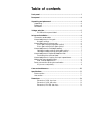
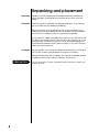
Operating Manual
Mark Levinson®
Nº28
Preamplifier
Madrigal Audio Laboratories, Inc.
15
WARNING: TO REDUCE THE RISK OF FIRE OR ELECTRIC SHOCK,
DO NOT EXPOSE THIS APPLIANCE TO RAIN OR MOISTURE.
CAUTION
RISK OF ELECTRIC SHOCK
DO NOT OPEN
CAUTION: TO REDUCE THE RISK OF ELECTRICAL SHOCK,
DO NOT REMOVE COVER. NO USER-SERVICEABLE PARTS
INSIDE. REFER SERVICING TO QUALIFIED PERSONNEL.
The lightning flash with arrowhead symbol, within an equilateral triangle, is intended to alert the
user to the presence of uninsulated “dangerous voltage” within the product’s enclosure that may
be of sufficient magnitude to constitute a risk of electric shock to persons.
The exclamation point within an equilateral triangle is intended to alert the user to the presence of
important operating and maintenance (servicing) instructions in the literature accompanying the
appliance.
16
Important safety instructions
Please read all instructions and precautions carefully and completely before operating your Nº28
Preamplifier.
1. ALWAYS disconnect your entire system from the AC mains before connecting or disconnecting
any cables, or when cleaning any component.
2. This product is equipped with a three-conductor AC mains power cord which includes an earth
ground connection. To prevent shock hazard, all three connections must ALWAYS be used. If
your electrical outlets will not accept this type of plug, an adapter may be purchased. If an
adapter is necessary, be sure it is an approved type and is used properly, supplying an earth
ground. If you are not sure of the integrity of your home electrical system, contact a licensed
electrician for assistance.
3. AC extension cords are not recommended for use with this product. If an extension cord must
be used, be sure it is an approved type and has sufficient current-carrying capacity to power
this product.
4. NEVER use flammable or combustible chemicals for cleaning audio components.
5. NEVER operate this product with any covers removed.
6. NEVER wet the inside of this product with any liquid.
7. NEVER pour or spill liquids directly onto this unit.
8. NEVER block air flow through ventilation slots or heatsinks.
9. NEVER bypass any fuse.
10. NEVER replace any fuse with a value or type other than those specified.
11. NEVER attempt to repair this product. If a problem occurs, contact your Mark Levinson® retailer.
12. NEVER expose this product to extremely high or low temperatures.
13. NEVER operate this product in an explosive atmosphere.
14. ALWAYS keep electrical equipment out of the reach of children.
17
From all of us at Madrigal Audio Laboratories, thank you for choosing the Mark Levinson® Nº28
Preamplifier.
A great deal of effort went into the design and construction of this precision device. Used properly, it
will give you many years of enjoyment.
18
Table of contents
Front panel ................................................................................................... 1
Rear panel ................................................................................................... 2
Unpacking and placement ....................................................................... 4
Unpacking .............................................................................................. 4
Placement ............................................................................................. 4
Ventilation .............................................................................................. 4
Voltage selection ........................................................................................ 5
PLS-228 bottom-panel label .......................................................... 5
Set-up and installation ................................................................................ 6
Connectors and cables ....................................................................... 6
Internal adjustments: line gain ............................................................. 6
Line gain settings ............................................................................ 6
Internal adjustments: phono gain ....................................................... 6
Phono gain settings (high-gain option) ....................................... 6
Phono gain settings (low-gain option) ......................................... 6
Internal adjustments: cartridge loading ............................................. 7
Cartridge loading settings (high-gain option) ............................ 7
Cartridge loading settings (low-gain option) .............................. 7
Internal adjustments: optional load terminals ................................... 7
Terminating the optional load ...................................................... 7
Internal adjustments: varying the input capacitance ...................... 8
Making the internal adjustments ......................................................... 8
Nº28, internal adjustments ............................................................. 8
Power connection and system activation ......................................... 9
AC power cord polarity ................................................................. 9
Care and maintenance ........................................................................... 10
Specifications ............................................................................................ 11
Phono section ...................................................................................... 11
Line section .......................................................................................... 11
Dimensions ................................................................................................. 12
Dimensions, Nº28, top view .......................................................... 12
Dimensions, Nº28, side view ......................................................... 12
Dimensions, PLS-228, top view ..................................................... 13
Dimensions, PLS-228, side view .................................................... 13
19
PHONO/
AUX 1
CD
5
TUNER
4
6
MADRIGAL AUDIO LABORATORIES
AUX 2
TAPE 1
AUX 3
3
TAPE 1
TAPE 2
TAPE 2
Nº 28
DEFEAT
INPUT
MONITOR
PREAMPLIFIER
7
8
2
9
1
10
OFF
INPUT SELECTOR
MONITOR SELECTOR
RECORD SELECTOR
OUTPUT LEVEL
1
2
3
4
Front panel
1
INPUT SELECTOR
Selects one of the seven inputs: CD, TUNER, PHONO/AUX 1, AUX 2,
AUX 3, TAPE 1, or TAPE 2.
2
RECORD SELECTOR
Selects between the program source (selected via the INPUT
SELECTOR), and either of two tape monitor inputs (selected via the
MONITOR SELECTOR).
In the DEFEAT position, the tape outputs are disconnected.
In the INPUT position, the tape outputs are connected while still
monitoring the selected source.
In the MONITOR position, the selected tape machine can be
monitored without affecting the signal at the tape outputs.
Note: Because of the switching arrangement employed in
the Nº28, we recommend that while making a critical
recording you don't operate the RECORD SELECTOR switch.
If you wish to monitor the signal from tape, set the RECORD
SELECTOR to MONITOR and use your tape machine's monitor
switch to switch between input and tape.
3
MONITOR SELECTOR
When the RECORD SELECTOR is in the MONITOR position, this selects
between the TAPE 1 and TAPE 2 inputs.
4
OUTPUT LEVEL
Adjusts volume at the main outputs.
The OUTPUT LEVEL control doesn't affect the tape outputs.
1
OUTPUTS
INPUTS
LEFT
PUSH
PUSH
PUSH
TAPE 1
LEFT
PHONO/
AUX 1
RIGHT
TAPE 2
TAPE 1
MAIN
PUSH
AUX 2
LEFT
TUNER
RIGHT
AUX 3
CD
POWER
SUPPLY
INPUT
TAPE 2
BALANCED MAIN
RIGHT
LEFT
GND
RIGHT
7
8
4
6
5
2
3
1
Rear panel
PRECAUTION
Disconnect all associated equipment from the AC mains BEFORE
making any signal connections and applying power to the Nº28.
Note: All left-channel RCA-type inputs and outputs are at the top of
the rear panel, and all right-channel RCA-type inputs and outputs are
at the bottom of the rear panel.
1
PHONO/AUX 1
If your Nº28 is equipped with the phono option, connect your
turntable's right-channel and left-channel signal leads to these
inputs. Connect the tonearm ground lead to the GND binding post
next to the inputs.
If your Nº28 isn't equipped with a phono option, these inputs will
accept signal leads from any line-level source equipment.
2
TUNER
Accepts right-channel and left-channel signal leads from a tuner
or other line-level source equipment.
3
AUX 3
Accepts right-channel and left-channel signal leads from line-level
source equipment.
4
TAPE 1, TAPE 2 (INPUTS)
Accept right-channel and left-channel signal leads from the tapeoutput connectors of a tape machine. These inputs can also be
used with other line-level source equipment.
5
AUX 2, CD
Accept right-channel and left-channel balanced signal leads from
a CD player or other source equipment with balanced output.
The pin assignments of these XLR-type female input connectors
are:
PUSH
2 1
3
2
Pin 1: Signal ground
Pin 2: Signal + (non-inverting)
Pin 3: Signal – (inverting)
Connector ground lug: chassis ground
Refer to the operating manual of your balanced-output line-level
source to verify that the pin assignments of its output connector
correspond to the Nº28. If not, wire the cable so that the
appropriate output pin connects to the equivalent input pin.
Note: If you won't be using the Nº28's balanced inputs and
need more single-ended inputs, it's possible to fabricate a
cable to connect line-level sources with single-ended output
to these balanced inputs:
Male RCA
(connect to
source)
1
3
2
22-guage
buss wire
6
Male XLR
(connect to
Nº28)
TAPE 1, TAPE 2 (OUTPUTS)
Connect these outputs to the right-channel and left-channel tape
inputs of your tape machine.
These outputs are unaffected by the OUTPUT LEVEL control on the
front panel of the Nº28.
7
MAIN
Connect these outputs to the right-channel and left-channel
inputs of your power amplifier or electronic crossover.
These outputs are affected by the OUTPUT LEVEL control on the
front panel of the Nº28.
8
BALANCED MAIN
If your power amplifier is equipped with balanced input
connectors, it's best to connect it to the Nº28 via these connectors,
particularly if long cable lengths are required.
Connect the right-channel and left-channel BALANCED MAIN
outputs of the Nº28 to the appropriate balanced inputs of the
power amplifier.
The pin assignments of these XLR-type male outputs are:
1 2
3
Pin 1: Signal ground
Pin 2: Signal + (non-inverting)
Pin 3: Signal – (inverting)
Connector ground lug: chassis ground
Refer to your power amplifier's operating manual to verify that the
pin assignments of its input connector correspond to the Nº28. If
not, wire the cable so that the appropriate output pin connects to
the equivalent input pin.
3
Unpacking and placement
Unpacking
Unpack your Nº28 Preamplifier and keep all packing materials for
future transport. Locate and remove all accessory items from the
cartons.
Placement
Carefully inspect the product for damage and flaws. If you find any,
see your Mark Levinson dealer immediately.
Place the Nº28 as close as possible to the source equipment, thus
keeping interconnect cabling as short as possible. It may be placed
on a shelf or in a cabinet where it's convenient to operate.
A two-meter DC cable is provided to connect the PLS-228 to the Nº28.
This allows you to place the PLS-228 so that it won't induce hum in the
Nº28 and other sensitive components. Other associated equipment
should also be placed so that it doesn't induce hum in the Nº28 and
other sensitive components.
Ventilation
Be sure to allow 3 to 4 inches of clearance above both the Nº28 and
the PLS-228, to allow heat dissipation through air circulation.
Mechanical drawings are included in this manual to facilitate special
installations and custom cabinet work (see "Dimensions").
PRECAUTION
4
For your protection, review "Important safety instructions" before you
install your Nº28.
Voltage selection
The PLS-228 is factory-set (internally) for 100V, 120V, 200V, 220V, or
240V AC mains operation @ 50 or 60Hz. Make sure that the label on
the bottom of the PLS-228 indicates the correct AC operating voltage
for your location.
PLS-228 bottom-panel
label
PLS-228 POWER SUPPLY
AC INPUT
WARNING: BEFORE ATTEMPTING TO
Voltage
indication
OPERATE THIS DEVICE, REFER TO
OWNER'S MANUAL FOR PROPER
OPERATING INSTRUCTIONS AND SAFETY
PRECAUTIONS. HAZARDOUS VOLTAGE
AVAILABLE INSIDE; DISCONNECT AC~
MAINS CABLE BEFORE REMOVING COVER.
OPERATING VOLTAGE:
90 – 110VAC~
210 – 240VAC~
105 – 125VAC~
230 – 250VAC~
~50 – 60HZ
180 – 220VAC~
100 – 120VAC~
MAINS 2A SLO–BLO 250VAC 3AB
FUSES: 200 – 240VAC~
1A SLO–BLO 250VAC 3AB
SERIAL NO.
DESIGNED AND MANUFACTURED IN U.S.A. BY
MADRIGAL AUDIO LABORATORIES INC.
If the voltage indicated is incorrect, see your Mark Levinson dealer.
If you wish to change the AC operating voltage of the Nº28/PLS-228,
see your Mark Levinson dealer.
The Nº28/PLS-228 can be powered by a normal 15-ampere AC mains
line. If other devices are also powered from the same AC line, their
additional power consumption must be taken into account.
5
Set-up and installation
Connectors and cables
The Nº28 incorporates RCA-type and XLR-type connectors for audio
signal input and output.
The Madrigal-designed RCA-type connectors used for single-ended
audio interconnection are a great improvement over ordinary RCAtype connectors. The gold-plated XLR-type connectors employed are
of European design, and are made to professional application
standards.
When connecting the Nº28 to source equipment and power
amplifiers, we recommend Madrigal Audio Laboratories HPC
Interconnect Cable. HPC is available in various lengths, terminated
with RCA, XLR, and Camac connectors. See your Mark Levinson
dealer for more information.
Internal adjustments:
line gain
The Nº28 offers internal gain adjustment of the line amplifiers, in 6dB
steps via two single-pole miniature rocker switches. These switches
have been factory-adjusted at 6dB/single-ended and 12dB/
balanced operation. In practice, you should have enough gain so
that normal listening is possible with the OUTPUT LEVEL set at
approximately 6.
If you wish to increase the line gain, see "Making the internal
adjustments;" refer to the table below for the proper switch positions
for each gain setting.
Line gain settings
Switch
#1
Off
Off
On
On
Internal adjustments:
phono gain
Gain
#2
Off
On
Off
On
Single-Ended Output
18dB
12dB
6dB
0dB
Balanced Output
24dB
18dB
12dB
6dB
The Nº28 is available with either a high-gain or low-gain phono option.
Each option offers two internally adjustable gain settings via two
single-pole miniature rocker switches, one for each channel. The highgain and low-gain phono options have been factory-adjusted at the
lowest gain settings (58dB and 38dB, respectively).
If you wish to increase the gain, see "Making the internal adjustments;"
refer to the tables below for the proper switch positions for each gain
settings.
Phono gain settings
(high-gain option)
Phono gain settings
(low-gain option)
6
Switch
#1
#2
On
Off
Off
On
Gain
58dB
64dB
Nominal Cartridge Output (3.54 cm/sec)
.2mV - .6mV
.2mV and Lower
Switch
#1
#2
On
Off
Off
On
Gain
38dB
44dB
Nominal Cartridge Output (3.54 cm/sec)
Greater than 2.0mV
2.0mV and Lower
Internal adjustments:
cartridge loading
The high-gain and low-gain phono options offer internally selectable
cartridge loading via four single-pole miniature rocker switches, one
for each channel. The high-gain and low-gain options have been
factory-adjusted at 825Ω and 47KΩ, respectively.
If you wish to change the factory-adjusted cartridge loading, see
"Making the internal adjustments;" refer to the table below for the
proper switch positions for each load setting.
Cartridge loading settings
(high-gain option)
Cartridge loading settings
(low-gain option)
Internal adjustments:
optional load terminals
Terminating the
optional load
Switch
#1
#2
#3
#4
30Ω
On
Off
Off
Off
100Ω
Off
On
Off
Off
825Ω
Off
Off
On
Off
10KΩ
Off
Off
Off
Off
Optional
Off
Off
Off
On
Switch
#1
#2
#3
#4
825Ω
On
Off
Off
Off
10KΩ
Off
On
Off
Off
22KΩ
Off
Off
On
Off
47KΩ
Off
Off
Off
Off
Optional
Off
Off
Off
On
Resistance values other than those listed above can be
accommodated via the optional load terminals. Load resistors can be
inserted into these terminals, allowing virtually any load desired.
Solder
Optional load
component
Solder
PC board
See "Making the internal adjustments;" refer to the "Cartridge loading
settings" tables for the proper switch positions for the optional load.
Because the inherent input resistance (all switches off) is in parallel with
the optional load terminals, use this formula to calculate the actual
resistor needed:
R = 1/ (1/RD - X)
RD = Desired Resistance in ohms
X = 0.00002 for Low-gain Phono Option,
0.0001 for High-gain Phono Option
Note: We recommend precision metal-film resistors; see your
Mark Levinson dealer.
7
Internal adjustments:
varying the input
capacitance
If you wish to vary the input capacitance of the phono option to
obtain the optimal value for a particular cartridge, a capacitor may
also be inserted into the optional load terminals (see "Terminating the
optional load" and "Making the internal adjustments").
Because the inherent input capacitance (all switches off) is in parallel
with the optional load terminals, use the following formula to calculate
the actual capacitor needed.
C = CR - CT - CP
C = The capacitor value
CR = Recommended capacitance value
CT = Tonearm capacitance including leads
CP = Preamplifier inherent shunt capacitance
(Low-gain phono option = 100pf; high-gain phono option = 1000pf)
Note: We recommend high-quality polypropylene, polystyrene
or Teflon capacitors; see your Mark Levinson dealer.
Making the internal
adjustments
1. Make sure all associated equipment is disconnected from the AC
mains, and that the PLS-228 is disconnected from the AC mains.
2. Using a 5/64" Allen key, remove the eight 6-32 flat-head socketcap screws securing the Nº28's top cover. Carefully lift the top
cover and remove it.
Nº28, internal adjustments
1
2
3
4
Cartridge loading
(right channel)
Phono gain
(right channel)
OFF
O 1
N
Optional load pins
2
O
F
F
Cartridge loading
(left channel)
Optional load pins
Phono gain
(left channel)
Line gain
3. Adjust the gain switches (using a ballpoint pen or similar
instrument) and install optional loads as desired.
4. Reassemble the Nº28.
8
Power connection and
system activation
Be sure all associated equipment is disconnected from the AC mains.
After making all signal connections and internal adjustments, connect
the ten-pin DC cable from the rear panel of the PLS-228 to the
connector on the rear panel of the Nº28.
Connect the AC cord to the male IEC connector on the rear panel of
the PLS-228, then connect the AC cord to the AC mains.
To PLS-228
To AC mains
AC power cord polarity
1
2
3
2
1
1 = Line (hot)
2 = Neutral
3 = Earth ground
3
The LED on the PLS-228 will light; after about five seconds, the LED on
the Nº28 will flash. After the LED begins flashing, turn the OUTPUT LEVEL
knob on the front panel of the Nº28 to its lowest (OFF) position (the LED
will stop flashing).
Allow the Nº28's circuitry to stabilize for 1 to 2 minutes, then connect all
associated equipment to the AC mains and activate it.
For optimal sonic performance and longevity, the Nº28/PLS-228 is
designed to remain powered at all times (a power-on/power-off
switch isn't provided).
Note: If AC mains power to the Nº28 is interrupted, the main
output will be muted. When power is restored, the main output
will remain muted and the LED will flash until the OUTPUT LEVEL
knob is turned to its lowest (OFF) position (the LED will stop
flashing). Allow the preamplifier circuitry to stabilize for 1 to 2
minutes; the OUTPUT LEVEL control will then function normally.
9
Care and maintenance
To remove dust from the cabinet of the Nº28, use a feather duster. To
remove dirt and fingerprints, we recommend isopropyl alcohol and a
soft cloth.
10
Specifications
The correlation between published specifications and sonic quality is
unreliable. A list of numbers reveals virtually nothing. All technical
measurements must be subject to qualitative as well as quantitative
interpretation.
Measurements of the Nº28 yield excellent results by any standards.
However, only those specifications that apply to its actual operation
are included here.
■
■
■
■
■
Power consumption:
50W maximum, depending on options
Mains voltage:
100V, 120V, 200V, 220V, or 240VAC @ 50/60Hz
Overall dimensions:
See "Dimensions"
Shipping weight (2 boxes):
29 lbs. (13.2kg)
Connector complement:
16 female RCA-type connectors
4 XLR-type female connectors
2 XLR-type male connectors
1 binding post (for turntable ground)
1 ten-pin connector
1 IEC mains connector
Phono section
■ Gain:
Selectable (see "Set-up and installation")
■ Moving-magnet phono option:
38dB, 44dB
■ Moving-coil phono option:
58dB, 64dB
■ Input impedance:
Selectable (see "Set-up and installation")
■ Output impedance:
10Ω
■ Maximum output (TAPE output):
6V
■ Recommended load (TAPE outputs):
10KΩ or greater
Line section
■ Gain:
Selectable (see "Set-up and installation")
■ Single-ended:
6dB, 12dB, 18dB
■ Balanced:
12dB, 18dB, 24dB
■ Input impedance:
15KΩ shunted by 220pf
■ Maximum output (MAIN outputs):
6V
■ Recommended load (TAPE outputs):
600Ω or greater
For more information, see your Mark Levinson dealer, or contact:
Madrigal Audio Laboratories, Inc.
2081 South Main Street (Route 17), P.O. Box 781
Middletown, Connecticut 06457 USA
Telephone (203) 346-0896
(FAX (203) 346-1540
If purchased in North America, this Mark Levinson product’s warranty is owner-transferable.
Warranty conditions are valid only in the country where the product was originally purchased.
For warranty information and conditions on products purchased outside of North America,
contact your local dealer or regional distributor.
11
Dimensions
3/8"
(9.5)
1/8"
(3.2)
Dimensions, Nº28, top view
1"
(25.4)
3/4" dia.
(19.1)
17-17/64"
(438.6)
15-17/64"
(387.8)
17-1/2"
(444.5)
1-1/2"
(38.1)
7-1/2"
(190.5)
10-7/8"
(276.3)
Dimensions, Nº28, side view
2-9/16"
(65.1)
2-3/4"
(69.9)
7/16"
(11.1)
12
7/64"
(2.5)
3/8"
(9.5)
3/16"
(4.8)
Dimensions, PLS-228,
top view
1-15/64"
(31.4)
3/4" dia.
(19.1)
8-3/16"
(208.0)
8-35/64"
(217.1)
5-3/4"
(146.1)
1-55/64"
(47.2)
9-1/16"
(230.2)
13-1/8"
(333.4)
Dimensions, PLS-228,
side view
2-39/64"
(66.3)
2-3/4"
(69.9)
7/16"
(11.1)
5/64"
(2.0)
13
MADRIGAL AUDIO LABORATORIES
2081 South Main Street, P.O. Box 781
Middletown, Connecticut 06457 USA
Telephone: (203) 346-0896
Fax: (203) 346-1540
®
is a registered trademark of Madrigal Audio Laboratories, Inc.
14
630080-2
©1993 Madrigal Audio Laboratories, Inc. All rights reserved.
Printed in U.S.A.