1
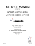
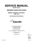
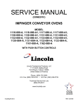
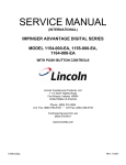
SERVICE MANUAL
(INTERNATIONAL)
IMPINGER CONVEYOR OVENS
MODEL 1621-000-EA, 1628-000-A, 1629-000-A
WITH PUSH BUTTON CONTROLS
Lincoln Foodservice Products, LLC
1111 North Hadley Road
Fort Wayne, Indiana 46804
United States of America
Phone : (800) 374-3004
U.S. Fax: (888) 790-8193 • Int’l Fax: (260) 436-0735
Technical Service Hot Line
(800) 678-9511
www.lincolnfp.com
1600AdDgElecExp
REV: 1/8/07
SEQUENCE OF OPERATIONS
IMPINGER ELECTRIC LOW PROFILE ADVANTAGE
(WITH PUSH BUTTON CONTROL)
MODEL 1621-000-EA 230/400 VAC 50HZ
MODEL 1628-000-A 220/380 VAC 50HZ
MODEL 1629-000-A 224/415 VAC 50HZ
POWER SUPPLY
CONTROL BOX
AUTO COOL DOWN
MAIN FAN CIRCUIT
TEMPERATURE
CONTROL
CONVEYOR DRIVE
AUTOMATIC COOL
DOWN
2
Electrical power to be supplied to the oven by a five conductor service.
Brown conductor is hot.
Black conductor is hot.
Black conductor is hot.
Blue conductor is neutral.
Green conductor is ground.
When the temperature in either one of the control boxes reaches 120°F ±3° (49°C ±
1.7°), the cooling fan thermostats will switch power to the cooling fans. The thermostats
will interrupt power to the cooling fans when the temperature falls to 100°F ± 3° (37°C ±
1.7°)
Line voltage is permanently supplied (through a power filter) to a normally open contact of
the oven power switch. Line voltage is permanently supplied to the two normally open
cooling fan thermostats. Closing the oven power switch supplies line voltage, through both
normally closed control box hi-limit thermostats, to the oven power relay. Its contacts now
close supplying line voltage to the two main fan motors. Closing the oven power switch also
supplies line voltage to the control box cooling fans, the oven control, the control
transformer, and the conveyor motor.
Closing the oven power switch supplies line voltage, through the 10 amp. fuse, through the
oven power relay, to the primary of the control transformer. 24VAC is supplied to the oven
control. The oven control is set to desired temperature. The thermocouple will provide
varying millivolts to the oven control. The oven control supplies line voltage to the contactor
at intermittent intervals to maintain desired temperature. The display on the oven control
will indicate when the contactor is energized.
NOTE: The display also indicates oven temperature.
Closing the oven power switch supplies line voltage, through the 10 Amp fuse, through the
oven power relay to the conveyor motor and to the primary of the control transformer.
Secondary voltage, 24VAC, is supplied to the oven control. Setting the oven control to the
desired time, outputs voltage, through a reversing switch, to the conveyor motor
NOTE: The conveyor system uses a magnet and hall effect sensor to prove operation of
the conveyor motor. If the conveyor motor is not running, “BELT JAM” is indicated on the
display.
When the oven is started, the time delay relay timing circuit is enabled, permitting the oven
fans to operate for approximately 20 minutes after the oven is shut off, to cool the oven.
The time delay relay will keep the coil of the motor relay closed, maintaining operation of
main fan and cooling motors.
Low Profile – 1600 Series Adv Dig Electric S.M. – Int’l
SCHEMATIC
MODEL 1621-000-EA, 1628-000-A, 1629-000-A
Low Profile – 1600 Series Adv Dig Electric S.M. – Int’l
3
TROUBLESHOOTING GUIDE
MODEL 1621-000 EA
230/400 VAC 50 HZ 3 PHASE
MODEL 1628-000 A
220/380 VAC 50 HZ 3 PHASE
MODEL 1629-000 A
240/415 VAC 50 HZ 3 PHASE
NOTE: When checking components on left side of unit, be sure to check for proper connections in power
connector, (marked P. C. on schematic diagram) located inside motor cover.
SYMPTOM
Oven fan will not
run
POSSIBLE CAUSE
Incoming power supply
Fuse, 10 A., main fan
Fuse holder
Filter, Power
Oven fan switch
20 minute time delay relay
Relay, main fan motors
Hi-limit thermostat(s), control
box
No main fan cool
down
No control box
cooling
Capacitor(s)
Motor(s), main fan
20 minute time delay relay
Fan switch
Hi-limit thermostat(s)
Relay, main fan motors
Cooling fan(s)
No automatic
control box cooling
4
Incoming power supply
EVALUATION
Check breakers/ reset if required call Power company
if needed.
Check, replace if necessary.
Check, replace if necessary.
Check for supply voltage to filter. If there is no voltage,
trace wiring back to fuse holder. If there is power in to
the filter, but no power out, replace the filter.
Check continuity between switch terminals.
Check for supply voltage to terminal #1 and #3, if
there is no voltage, trace wiring back to the power
filter. If voltage is present, check for supply voltage at
terminals #3 to #6, if no voltage is present, trace
wiring back to on/off switch. If there is voltage at #3
and #6, check for voltage at terminals #1 and #2, of
there is no voltage at Terminals #1 and #2, replace
the 20 minute time delay relay.
Check for power to coil of motor relay. If no voltage is
present, trace wiring back to 20 minute time delay
relay. Check for supply voltage to the contact of the
relay. If no voltage is present, trace wiring back to
power filter. If voltage is present, at the relay coil,
check to insure the contacts are closing. Replace
relay as needed.
Terminals are normally closed, if open, reset
thermostat and test oven for proper operation. If it will
not reset, replace thermostat.
Check for opens, shorts, or grounds.
Check for opens, shorts, or grounds.
Check for supply voltage at terminals #1 and #2 while
is “ON”. Turn “OFF” the main fan switch, supply
voltage should continue to be present for 20 minutes.
If voltage is not present for 20 minutes, replace 20
minute time delay relay.
(SEE OVEN FAN WILL NOT RUN.)
Terminals are normally closed, if open, reset
thermostat and test oven for proper operation. If it will
not reset, replace thermostat.
Check for power to coil of oven fan relay. If no voltage
is present, trace wiring back to hi-limit thermostat.
Check for supply voltage to the contact of the relay. If
no voltage is present, trace wiring back to fuse holder.
If voltage is present, at the relay coil, check to insure
the contacts are closing. Replace relay as needed.
Supply voltage should now be at these motors. If
voltage is present, check motor for open, shorts, or
grounds. WITH POWER OFF: check for locked rotor.
Check circuit breakers, reset if needed. Call power
company if needed.
Low Profile – 1600 Series Adv Dig Electric S.M. – Int’l
Cooling fan thermostat(s)
Check the cooling fan thermostat. (Thermostat closes
at 49°C and opens at 38°C). With the cooling fan
thermostat preheated, check for continuity. If switch is
open, replace.
Fuse, 3 A., cooling fan
Check, replace if necessary.
Fuse holder
Check, replace if necessary.
Cooling fan(s)
Supply voltage should now be at these motors. If
voltage is present, check motor for opens, shorts or
grounds. WITH POWER OFF: Check for locked rotor.
Oven will not heat
Fan switch
Check to see that the fan switch is on.
Main oven fan
Check if main oven fan is operating. If not, refer to
“Oven fan will not run”.
NOTE: These ovens utilize 2 complete /Temperature control systems. Each system will Follow the same
troubleshooting sequence.
Oven control relay
Check for line voltage to the relay coil. If no voltage is
present, trace wiring back to the control box hi-limit
thermostat(s). If voltage is present, check to insure
contacts are closing. Replace relay as needed.
Thermostat, oven cavity hi-limit
Terminals are normally closed. If open, reset and test
oven for proper operation. If thermostat will not hold
for maximum oven temperature, and oven is not
exceeding maximum temperature dial setting, check
for proper location of capillary bulb in its spring holder
If above checks OK, replace hi-limit.
Contactor, hi-limit
Check for line voltage to the contactor coil. If no
voltage is present, trace wiring back to the oven cavity
hi-limit thermostat(s). If voltage is present, check to
insure contacts are closing. Replace contactor as
needed.
Fuse, heater, 50A.
Check, replace if necessary.
Fuseholder
Check, replace if necessary.
Control transformer
Check for supply voltage to the primary of the control
transformer. If no voltage is present, trace wiring back
to the oven control relay. If primary voltage is present,
check for 24VAC at the transformer secondary. If
there is primary voltage, but no secondary voltage,
replace control transformer.
Oven control
Check for 24VAC supply to control. If no voltage is
present, trace wiring back to control transformer. If
24VAC is present, check for a read-out on the control
display. If there is 24VAC supplied, but there is no
read-out on the control display, replace the oven
control.
If there is a read-out on the control, set the control to
maximum temperature (see installation operations
manual for temperature adjustment). With the control
set at maximum temperature, check for line voltage at
the heat relay (mercury contactor). If there is voltage
at the heat relay, proceed to “Heat relay” for next
check. If there is no voltage at the heat relay, trace
wiring back to the oven control. If there is no voltage
output at the oven control, check the read-out on the
control. If the control reads “LP FAIL” or “RP FAIL”,
this indicates that the thermocouple has failed or has
become disconnected from the control. “LP FAIL”
indicates a problem with the left thermocouple probe,
and “RP FAIL” indicates a problem with the right
thermocouple probe.
Low Profile – 1600 Series Adv Dig Electric S.M. – Int’l
5
Thermocouple probe
Oven control
Thermocouple
Oven control
Oven air pressure switch
Heat relay
Heating elements
6
Check to be sure that the thermocouple is securely
connected to the oven control. If the thermocouple is
connected to the oven control, and the control
indicates “LP FAIL” or “RP FAIL”, disconnect the
thermocouple from the oven control and measure the
resistance of the thermocouple. The left thermocouple
should read approx. 21Ω. The right thermocouple
should read approx. 11Ω. If these readings are not
achieved, replace the thermocouple. If these readings
are correct, proceed.
If the thermocouple checks good, but the oven control
display indicates that there is a thermocouple failure,
replace the oven control. If the oven control indicates
a temperature reading but the oven will not heat,
proceed.
WITH POWER ON AND THERMOCOUPLE
ATTACHED TO THE OVEN CONTROL: Measure the
DC millivolt output of the thermocouple. Refer to the
thermocouple chart (located in the “Removal” section
of the manual) for proper millivolt readings. If these
readings are not achieved, replace thermocouple.
If the thermocouple checks good, but there is no
voltage output to the temperature regulation valve,
replace the oven control. If there is voltage output to
the heat relay, proceed.
Check for supply voltage at the air pressure switch, if
no voltage is present, trace wiring back to the oven
control. Check for supply voltage on both sides of
switch. If voltage is present on one side only, check
for air tube blockage. Adjust air pressure switch. If the
above fails, replace air pressure switch.
Check for line voltage supplied to the coil of the heat
relay. If no voltage is present, trace wiring back to the
air pressure switch. If voltage is present, check to be
certain that all of the contacts are closing when the
relay is energized.. Also check for opens or shorts in
the operating coil. Replace temperature regulation
valve as needed.
Check the Amp draw on each power lead for proper
load. Check the specification plate for proper rating
information.
If the Amp draw is high or low, check the individual
heating elements for opens, shorts and proper
resistance.
To check the resistance of the elements,
TURN OFF THE POWER!
Remove all wiring from the heating elements and use
an accurate digital meter.
The element resistance should be as follows:
220V – 29 ohms approx.
230V – 32 ohms approx.
240V – 34 ohms approx.
If all readings are not correct, replace heating
elements as needed.
Low Profile – 1600 Series Adv Dig Electric S.M. – Int’l
Intermittent heating
Thermal overload of main
fan motor(s)
Conveyor will not
run
Power supply
Power switch
Fuse, 10 Amp.
Fuse holder
Hi-limit thermostat(s),
control box
Relay, oven control
Control transformer
Conveyor motor
Capacitor, conveyor motor
Switch, conveyor reversing
Oven control
Conveyor motor
runs, but there is
no speed display
NOTE: Display will indicate
“Belt jam”
Oven control
Low Profile – 1600 Series Adv Dig Electric S.M. – Int’l
The main fan motors are equipped with internal
thermal protection and will cease to operate if
overheating occurs. As the motors overheat and then
cool, this will cause the units to cycle on and off
intermittently. Improper ventilation or lack of
preventive maintenance may cause this problem.
Also, most of the problems listed under “Oven will not
heat” can cause intermittent failure.
Check for supply voltage at terminals L1 and L2. If
voltage is not present check breakers.
Check continuity between switch terminals. Replace
switch as needed.
Check and/or replace.
Check and/or replace.
Check for voltage on both sides of the switch.
Terminals are normally closed. If open, reset and test
for proper operation. If thermostat will not hold, and
the control box temperature is not exceeding 140°F
(60°C), replace thermostat.
Check for line voltage to the relay coil. If voltage is not
present, trace wiring back to the hi-limit thermostat. If
voltage is present, check to insure contacts are
closing. Replace relay as needed.
Check for line voltage supply to the primary of the
control transformer. If no voltage is present, trace
wiring back to the oven power relay. If voltage is
present, check for 24VAC at the transformer
secondary. If there is primary voltage, but no
secondary voltage, replace control transformer.
Check for line voltage supply to the conveyor motor at
wire #28 to neutral. If no voltage is present, trace
wiring back to the oven power relay. If voltage is
present and the motor will not run, check the motor
windings for opens or shorts.
WITH POWER OFF: Check the motor windings as
follows:
Grey to black - 116 ohms
Grey to brown - 116 ohms
Brown to black - 230 ohms
Check for shorts or grounds. Replace capacitor as
needed.
WARNING: Capacitor has a stored charge, discharge
before testing.
Check continuity between switch terminals, Replace
switch as needed.
If there is supply voltage to the motor. And the motor,
capacitor, and reversing switch check good, replace
the oven control.
Check for output voltage from the oven control to hall
effect sensor (sensor is located in conveyor motor).
Measure voltage at the motor connector, red wire and
yellow wire. Voltage should be approx. 10VDC. If no
voltage is present, trace wiring back to oven control. If
there is no voltage present at the oven control,
replace the oven control.
7
Conveyor motor
Oven control
8
If there is voltage supplied to the hall effect sensor,
check for a frequency output from the hall effect
sensor. Measure frequency across the yellow and
white wires at the motor connector. Frequency
readings should be approx. 20 – 525 Hz. If these
readings are not achieved, replace the conveyor
motor. If the readings are achieved, proceed.
If the hall effect sensor readings are correct, but there
is no speed indicated on the display, replace the oven
control.
Low Profile – 1600 Series Adv Dig Electric S.M. – Int’l
REMOVAL, INSTALLATION & ADJUSTMENTS
MODEL SERIES 1621-000-EA, 1628-000-A, 1629-000-A
CAUTION!
BEFORE REMOVING OR INSTALLING ANY COMPONENT IN THE
IMPINGER OVEN BE SURE TO DISCONNECT ELECTRICAL POWER AND GAS SUPPLY.
AIR PRESSURE SWITCH – REPLACEMENT
A.
B.
C.
D.
E.
Remove control panel top.
Disconnect wires from switch making note of wire number and location for reinstallation.
Remove air tube from switch assembly.
Remove switch from control box.
Install new switch in reverse, make sure air tube is not blocked or misaligned.
To adjust air pressure switch, remove cover from the switch to expose adjusting screw. To
increase sensitivity, turn screw counter- clockwise; to decrease sensitivity, turn screw
clockwise.
CONVEYOR DRIVE MOTOR – REPLACEMENT
A.
B.
C.
D.
E.
F.
G.
H.
Shut off power at main breaker.
Remove conveyor.
Remove control panel top and front cover.
Disconnect wiring from motor and mark for reassembly.
Remove sprocket from motor shaft.
Remove 4 screws and remove conveyor motor and mounting bracket.
Remove mounting bracket from conveyor motor assembly.
Reassemble in reverse order.
CAPACITOR, CONVEYOR MOTOR – REPLACEMENT
A.
B.
C.
D.
E.
Shut off power at main breaker.
Remove control box cover and front panel.
Discharge capacitor before removing wires. Mark wires for reassembly.
Remove mounting screw and remove capacitor.
Reassemble in reverse order.
REVERSING SWITCH – REPLACEMENT
A.
B.
C.
D.
E.
Shut off power at main breaker.
Remove control box cover and front panel.
Disconnect wiring from reversing switch and mark for reassembly.
Remove mounting nut and remove reversing switch.
Reassemble in reverse order and check system operation.
REVERSING CONVEYOR DIRECTION
A. Shut off power at oven switch.
B. Set reversing switch in the other position.
C. Turn oven “on” and check for proper operation.
FUSEHOLDER – REPLACEMENT
A. Shut off power at main breaker.
B. Remove appropriate control box cover.
Low Profile – 1600 Series Adv Dig Electric S.M. – Int’l
9
C. Remove 2 wires, note wire number and location.
D. Remove locknut on backside of fuse holder and push out.
E. Reinstall in reverse order and check system operation.
THERMOSTAT, HIGH LIMIT, OVEN CAVITY – REPLACEMENT
A. Shut off power at main breaker.
B. Remove appropriate control box cover. Remove motor cover and remove oven back to access
high limit thermostat sensing bulb.
C. Remove wires from thermostat, note wire numbers for reinstallation.
D. Remove mounting nut from high limit thermostat and remove high limit from oven.
E. Reassemble in reverse order. Check system operation.
ON-OFF SWITCH (POWER) – REPLACEMENT
A.
B.
C.
D.
E.
Shut off power at main breaker.
Remove control box cover.
Depress spring clips on side of switch and push out.
Remove wires from back of switch, note wire number and location.
Reassemble in reverse order and check system operation.
NOTE: Make sure switch housing is fully seated in control box housing.
CAPACITOR, MAIN FAN MOTOR – REPLACEMENT
A. Shut off power at main breaker.
B. Remove appropriate control box cover.
C. Remove 2 wires from capacitor, note wire number and location. WARNING: Capacitor has a
stored charge, discharge before handling or testing.
D. Cut 2 tyraps securing capacitor to base and replace.
E. Reinstall in reverse order and check system operation.
RELAY – REPLACEMENT
A.
B.
C.
D.
E.
F.
Shut off power at main breaker.
Remove control box cover.
Remove wires from relay, note wire numbers and location for reinstallation.
Remove 2 screws from relay base and replace relay.
Reassemble in reverse order making sure wire connections are properly seated.
Check system operation.
THERMOSTAT, COOLING FAN – REPLACEMENT
A.
B.
C.
D.
E.
Shut off power at main breaker.
Remove appropriate control box cover, remove rear cover.
Remove 2 wires from thermostat, note wire number and location.
Remove 2 mounting screws and replace thermostat.
Reassemble in reverse order and check system operation.
HIGH LIMIT THERMOSTAT,CONTROL BOX – REPLACEMENT
A. Shut off power at main breaker.
B. Remove appropriate control box cover.
C. Remove 2 wires from thermostat, note wire numbers and location for reinstallation
D. Remove screws from bracket and remove thermostat.
E. Reassemble in reverse order and check system operation.
NOTE: Depress reset button to insure thermostat is set for operation.
10
Low Profile – 1600 Series Adv Dig Electric S.M. – Int’l
COOLING FAN MOTOR – REPLACEMENT
A.
B.
C.
D.
E.
Shut off power at main breaker.
Remove appropriate control box cover.
Remove 4 mounting screws.
Unplug electrical connector and remove fan motor.
Reassemble in reverse order and check system operation.
MAIN FAN MOTOR – REPLACEMENT
A. Shut off power at main breaker.
B. Shut off gas supply and remove gas line and manifold lines from back of oven.
C. Remove screws from motor cover housing and lift off.
NOTE: When ovens are stacked, all motor cover housings are fastened together.
D. Unplug power connector.
E. Unplug thermocouple.
F. Unplug 2 motor connectors.
G. Remove 8 bolts from oven back ( 4 left, 4 right ) and lift out.
H. Remove 1 screw from fan hub and slide fan blade off of motor shaft. ( note location of fan blade
for reinstallation )
I. Loosen locknuts on cone. Remove 2 mounting bolts and remove motor from back assembly.
J. Remove 4 hex head screws from motor mount bracket. Remove motor mount from motor and
reinstall on new motor.
K. Reassemble in reverse order. NOTE: 1. Make sure motor is centered in back housing.
2. Verify correct location of fan blade and that it is not hitting fan shroud.
3. Make sure all connectors are properly seated and making good contact.
4. When reinstalling gas manifold across back of oven, check all fittings for leaks.
L. Check system operation (allow 30 minute preheat for all checks) NOTE: Position of the fan on
the motor shaft will be 1.875” from the top of the oven back cone to the blade spider assembly
on the fan hub. (see drawing below ).
THERMOCOUPLE (TYPE K) – REPLACEMENT
A. Shut off power at main breaker.
B. Remove control box covers. Remove motor cover and remove oven back to access
thermocouple.
NOTE: Removal of oven back assy. Is required to replace thermocouples.
C. Remove thermocouple from wire form in oven chamber and remove from chamber.
NOTE: R. H. thermocouple (viewed from front) is connected directly to the temperature control
board, remove 2 wires , make note of wire colors and location. When changing L. H.
thermocouple (viewed from front, the back motor cover must also be removed to gain access to
the thermocouple connector plug.)
D. Reassemble in reverse order making sure bulb is placed securely in the wire form in the oven
chamber.
E. Check system operation, recalibrate as needed. NOTE: The R. H. and L. H. thermocouples
have different connectors on the wire ends and must be ordered accordingly.
THERMOCOUPLE MEASUREMENT
TEMPERATURE (°F)
200°
250°
300°
350°
400°
450°
500°
550°
600°
D.C. MILLIVOLTS
2.8
4.0
5.1
6.0
7.1
8.2
9.3
10.4
11.5
Low Profile – 1600 Series Adv Dig Electric S.M. – Int’l
11
TIME DELAY RELAY – REPLACEMENT
A. Shut off power at main breaker.
B. Remove control box cover.
C. Remove all wires from time delay relay, note wire numbers and location for reinstallation.
D. Remove mounting screw and remove time delay relay.
E. Reassemble in reverse order and check system operation.
HEATING ELEMENT – REPLACEMENT
A. Shut off power at main breaker.
B. Remove appropriate control box cover.
C. Remove wires from heating element, note all wire numbers for reinstallation.
D. Reassemble in reverse order and check system operation. NOTE: Be sure that leading edge of
heating element is located in heating element mounting bracket, located in oven cavity.
CONTACTOR – REPLACEMENT
A. Shut off power at main breaker.
B. Remove appropriate control box cover.
C. Remove all wires from contactor, note all wire numbers for reinstallation.
D. Remove mounting screws and remove contactor.
E. Reassemble in reverse order and check system operation.
POWER FILTER – REPLACEMENT
A. Shut off power at main breaker.
B. Remove control box cover.
C. Remove all wires from the power filter, note all wire numbers for reinstallation.
D. Reassemble in reverse order and check system operation.
BEARING, CONVEYOR – REPLACEMENT
A. Remove conveyor from oven and place on a flat work surface.
B. Remove connecting links from conveyor belting. See Installation and Operating Instructions
Manual.
C. Remove conveyor belting from conveyor. Remove drive sprocket from drive shaft.
D. Move drive shaft or idle shaft toward end of conveyor, and shaft with bearings will now slip out
of holding bracket.
E. Replace bearing and reassemble in reverse order.
CONTROL TRANSFORMER – REPLACEMENT
A. Shut off power at main breaker.
B. Remove wires from primary side, note color and location.
C. Remove wires from secondary side, note color and location.
D. Remove two mounting screws and remove transformer.
E. Reassemble in reverse order and check system operation.
OVEN CONTROL – REPLACEMENT
A. Shut off power at main breaker.
B. Remove control box cover and front panel.
C. Remove all wiring connections and mark for reassembly.
D. Remove oven control by pulling control from mounting pins. Remove control from oven.
E. Before installing new control, set voltage jumper (located at the bottom center of the oven
control) to the proper (120/240V) position. Install the four push button extensions (included with
the oven control) by pushing the extensions onto the four set buttons on control.
F. Reassemble in reverse order and check system operation.
G. Set the oven control for the proper operating mode. The 1600 series ovens have dual burner
systems. The oven control must be set to the “Dual oven mode”. Set control as follows: With
the oven power switch “off”, depress the “temp” and “down” buttons and turn the oven “on”.
Control will indicate “Low Pro”. Release the buttons, the control will indicate “Temp to store”.
Press the “temp” button. The control is now set for dual burner operation.
12
Low Profile – 1600 Series Adv Dig Electric S.M. – Int’l
NOTES: All bake times should be within 10 seconds of set bake time, cavity temperature should be calibrated to within
5° of set temperature. For temperature calibration, allow oven temperature to stabilize at least for 30 minutes.
2 BEFORE APPLYING POWER TO OVEN, ENSURE PROPER VOLTAGE JUMPER SETTING FOR 120V or 240V, AND THE
50 HZ / 60HZ JUMPER SETTING IS CORRECT. JUMPERS ARE LOCATED AT BOTTOM CENTER OF CONTROL BOARD.
3 Set digital control for proper oven cavity and conveyor belt during power-up.
A. Single Cavity Ovens - Impinger I or II
Press and hold the 2 inside buttons while turning the power switch on. After Imp. I or II is displayed, release the
buttons and control will request the conveyor belt setting - Imp. I or Lo Pro - or Imp. II. The up or down button will
toggle between these choises. When desired conveyor belt is selected, press the temp. button to store settings.
B. Dual Cavity Ovens - Impinger Low Profile
Press and hold the 2 outside buttons while turning the power switch on. After Imp. Lo Pro is displayed, release
the buttons and control will request the conveyor belt setting - Imp. I or Lo Pro - or Imp. II. The up or down button will
toggle between these choises. After the '
Imp. I or Lo Pro'conveyor belt is selected, press the temperature button to
store settings.
4 Set digital control for proper temperature scale — F or C
A. Press and hold the 2 RH buttons to enter Sub-Level program. A prompt will be displayed "Technicians Only"
After a couple seconds a second prompt will say "Please Release Buttons" After releasing the buttons, quickly
press the TIME button and the UP button to enter the program. After Sub Set Point is displayed, press temp. button
to indicate Scale. The up or down buttons will toggle choices between F or C. After desired scale is selected, allow
control to go into normal run mode. These special promps are for Prom chips 007 and above.
Prom chips 006 and below, the Sub-Level program can be entered by pressing the two right buttons only.
5 Set bake time and oven temperature — Set Point Menu
A. Press and hold the 2 LH buttons to enter Set Point program. Once in set point program, press temp. button and adjust
temperature using up or down arrows. Press time button while still in set point program and adjust time using up or
down buttons. Pressing time or temp. button will show what that respective setting is. Once desired settings are
programmed, allow control to go into normal running mode.
B. For normal calibration, set bake time to 10:00 and temperature to 500°F/260°C. Bake time can be checked using standard QA
procedures. Install cavity temperature probes per standard QA procedures.
6 Adjusting temperature offset — Sub Set Point Menu
A. Follow the instructions in Step 4. to enter the Sub-level program. After Sub Set Point is displayed, pressing the temp.
button will access the following temperature features:
SCALE (F or C), HI TEMP, LOW TEMP, OFFSET (+ or -), MANUFACTURE MODE (Clear or Active).
•Do not change SCALE after it was set in step 4A, or settings will reset to default
values.
B. To adjust the temperature offset, access the OFFSET display in the Sub Set Point Menu. If cavity temperature is
above the set temperature, decrease (down button) the offset value. If cavity temperature is below the set
temperature, increase (up button) the offset value. The amount of offset needed should be the difference between
the cavity temp. and the set temp. Allow oven to reach set temp. and verify cavity temperature. Readjust offset as necessary.
C. HI TEMP and LOW TEMP are not normally changed unless requested by the customer. Accessing these displays and
pressing the up or down buttons will change each indicated setting accordingly.
D. MANUFACTURE MODE is not normally used, so this feature should be set to '
clear'
.
E. While in Sub Set Point Menu, pressing the time button will access the following time features:
HI TIME and LOW TIME. These are not normally changed unless requested by the customer. Accessing these
displays and pressing the up or down buttons will change each indicated setting accordingly.
Low Profile – 1600 Series Adv Dig Electric S.M. – Int’l
13
GENERAL
ADVANTAGE SERIES
LETTER
PART #
DESCRIPTION
A
B
C
D
E
F
G
H
J
K
L
M
N
O
P
Q
R
S
369110
369929
369926
369925
369927
369930
369211
369058
1609
370252
369745
369723
369783
369717
369057
369501
369328
369030
369390
370167
370663**
370166
370662**
370168
370665***
370169
370664***
Access window assembly
Window retainer
Window frame bottom
Glass, access window
Window frame, top
Screw, 10-32x1/4
Thumb screw
Baffle
Oven top
Drive cover, R.H.
Hinge assy., right
Door assy., small
Latch, spring
Finger retaining bracket
Screw, finger retaining bracket
Latch
Leg
Caster, High stand
Caster, Low stand
Baffle, air return U.L., L.R. (S/N 35950 & below)
Baffle, air return U.L. (S/N 35951 & above)
Baffle, air return U.R. L.L. (S/N 35950 & below)
Baffle, air return U.R. (S/N 35951 & above)
Finger housing T-1, T-3, B-2, B-4 (S/N 35950 & below)
Finger housing T-1, T-3, B-2, B-4 (S/N 35951 & above)
Finger housing T-2, T-4, B-1, B-3 (S/N 35950 & below)
Finger housing T-2, T-4, B-1, B-3 (S/N 35951 & above)
Columnating plates- see Installation
Operations manual.
Finger cover
Handle assy.
Door assy. , large
Screw, 8-32x3/8
Hinge assy.
T
U
V
W
X
Y
Z
AA
BB
369707
369740
369718
369931
369746
** Units from S/N 35951 and above DO NOT contain lower Air Return Baffles. These units only
contain a total of two (2) Air Return baffles which are placed above the top finger assemblies.
*** These parts have minor changes not shown in the exploded view drawing on page 15.
14
Low Profile – 1600 Series Adv Dig Electric S.M. – Int’l
GENERAL VIEW
Low Profile – 1600 Series Adv Dig Electric S.M. – Int’l
15
CONTROL BOX, RIGHT
1621-000-EA, 1628-000-A, 1629-000-A
LETTER
PART #
DESCRIPTION
A
B
9004646
369767
369792
369769
7004973
369025
370361
369119
369134
370117
369378
369766
369793
369768
7004970
370251
7002976
369192
370485
369368
357107
369013
369014
357107
369431
369507
370241
370360
7005624
370256
369125
369422
370180
370354
370355
369432
370257
369158
370357
370466
Control Box Front RH
Firebar Element, Bottom 220V
Firebar Element, Bottom 230V
Firebar Element, Bottom 240V
Mounting Plate Bottom
Switch, Blower Air
Motor Assembly L/P CE ADV
Fuse holder 3 Pole
Fuse, 50 A.
Terminal Block 5 Pole
Cooling Fan Motor 230VAC
Firebar Element, Top 220V
Firebar Element, Top 230V
Firebar Element, Top 240V
Mounting Plate, Top
Top Assembly RH
Capacitor Bracket
Capacitor
Contactor, Mercury 3P
Thermostat, oven cavity hi-limit
Fuse Holder
Fuse, 3 Amp
Fuse, 10 Amp
Fuse holder
Thermostat, control box hi-limit
Thermostat, cooling fan
Transformer 240V-24V
Capacitor 230V Digit
Bracket, Component Assembly
Panel Side Control RH
Terminal Block, 2 Pole
Relay, Fan 240V
Filter EMI
Bush Button Facia
Digital Control Board
Switch, Rocker Lighted
Bracket Gearmotor Mount
Sprocket, 10 Tooth
Thermocouple, right
Timer, cool down, 20 minute
C
D
E
F
G
H
I
J
K
L
M
N
O
P
R
S
T
U
V
X
Z
AA
AB
AC
AD
AE
AF
AG
AH
AJ
Not shown
Not shown
16
Low Profile – 1600 Series Adv Dig Electric S.M. – Int’l
CONTROL BOX, RIGHT VIEW
Low Profile – 1600 Series Adv Dig Electric S.M. – Int’l
17
CONTROL BOX, LEFT
1621-000-EA, 1628-000-A, 1629-000-A
LETTER
PART#
DESCRIPTION
A
B
C
D
E
7006233
370250
369378
370495
369766
369793
369768
7004970
369767
369792
369769
7004973
7006234
369025
370272
369507
369431
7005624
370485
369368
7002976
369192
370358
Control Box, Back LH
Top Assembly LH
Cooling Fan Motor 230VAC
Bracket Fan RH
Firebar Element, Top 220V
Firebar Element, Top 230V
Firebar Element, Top 240V
Mounting Plate, Top
Firebar Element, Bottom 220V
Firebar Element, Bottom 230V
Firebar Element, Bottom 240V
Mounting Plate, Bottom
Control Box, Front LH
Air Switch, Blower
Panel, Control Box Side LH
Thermostat, cooling fan
Thermostat, control box hi-limit
Bracket Component
Contactor, Mercury 3P
Thermostat, oven cavity hi-Limit
Bracket Capacitor
Capacitor 7.5 MFD
Thermocouple, left
F
G
H
I
J
L
M
N
O
P
R
S
T
Not shown
18
Low Profile – 1600 Series Adv Dig Electric S.M. – Int’l
CONTROL BOX, LEFT VIEW
Low Profile – 1600 Series Adv Dig Electric S.M. – Int’l
19
OVEN BACK
1621-000-EA, 1628-000-A, 1629-000-A
20
LETTER
PART#
DESCRIPTION
A
B
C
D
E
F
G
H
I
J
L
369547
369725
369776
369777
369778
369761
369759
1627
369033
370245
369724
Wire form thermostat bulb
Fan, clockwise rotation
Fan shroud
Stand-off
Rear wall assy.
Motor mount
Motor, main fan 220/240V 50 Hz.
Duct cap
Motor clamp
Rear duct
Fan, counter-clockwise rotation
Low Profile – 1600 Series Adv Dig Electric S.M. – Int’l
OVEN BACK VIEW
Low Profile – 1600 Series Adv Dig Electric S.M. – Int’l
21
CONVEYOR
1621-000-EA, 1628-000-A, 1629-000-A
LETTER
A
B
C
D
E
F
G
H
I
J
K
L
M
N
O
P
22
PART#
DESCRIPTION
369830
369002
369362
369314
2114003
369812
369160
369641
369220
369005
369811
369161
369813
369825
370247
370050
369806
369163
Complete conveyor
Knob, conveyor tension
Belt, 1ft. section (32 inch wide belt)
Roll, conveyor, notched
nut, hex
Conveyor idler shaft
Conveyor pan stop
Bracket, idle bearing
Bearing, idle
Connecting link (32 inch wide belt)
Conveyor drive shaft
Roller chain sprocket
Conveyor bearing block
Retaining ring
Drive chain
Conveyor frame
Crumb pan
Conveyor belt, complete (32 inch wide belt)
Low Profile – 1600 Series Adv Dig Electric S.M. – Int’l
CONVEYOR VIEW
Low Profile – 1600 Series Adv Dig Electric S.M. – Int’l
23
24
Low Profile – 1600 Series Adv Dig Electric S.M. – Int’l