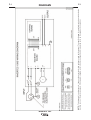
1
IM10060
RETURN TO MAIN MENU
INVERTEC®100S
For use with machines having Code Numbers:
September, 2010
11673
Safety Depends on You
Lincoln arc welding and cutting
equipment is designed and built
with safety in mind. However,
your overall safety can be
increased by proper installation
... and thoughtful operation on
your part. DO NOT INSTALL,
OPERATE OR REPAIR THIS
EQUIPMENT WITHOUT READING THIS MANUAL AND THE
SAFETY PRECAUTIONS CONTAINED THROUGHOUT. And,
most importantly, think before
you act and be careful.
OPERATOR’S MANUAL
Copyright © Lincoln Global Inc.
• World's Leader in Welding and Cutting Products •
• Sales and Service through Subsidiaries and Distributors Worldwide •
Cleveland, Ohio 44117-1199 U.S.A. TEL: 216.481.8100 FAX: 216.486.1751 WEB SITE: www.lincolnelectric.com
i
i
SAFETY
WARNING
CALIFORNIA PROPOSITION 65 WARNINGS
Diesel engine exhaust and some of its constituents
are known to the State of California to cause cancer, birth defects, and other reproductive harm.
The Above For Diesel Engines
The engine exhaust from this product contains
chemicals known to the State of California to cause
cancer, birth defects, or other reproductive harm.
The Above For Gasoline Engines
ARC WELDING CAN bE HAzARDOUS. PROTECT YOURSELF AND OTHERS FROM POSSIbLE SERIOUS INJURY OR DEATH.
KEEP CHILDREN AWAY. PACEMAKER WEARERS SHOULD CONSULT WITH THEIR DOCTOR bEFORE OPERATING.
Read and understand the following safety highlights. For additional safety information, it is strongly recommended that you
purchase a copy of “Safety in Welding & Cutting - ANSI Standard Z49.1” from the American Welding Society, P.O. Box
351040, Miami, Florida 33135 or CSA Standard W117.2-1974. A Free copy of “Arc Welding Safety” booklet E205 is available
from the Lincoln Electric Company, 22801 St. Clair Avenue, Cleveland, Ohio 44117-1199.
bE SURE THAT ALL INSTALLATION, OPERATION, MAINTENANCE AND REPAIR PROCEDURES ARE
PERFORMED ONLY bY QUALIFIED INDIVIDUALS.
FOR ENGINE
powered equipment.
1.h. To avoid scalding, do not remove the
radiator pressure cap when the engine is
hot.
1.a. Turn the engine off before troubleshooting and maintenance
work unless the maintenance work requires it to be running.
____________________________________________________
1.b. Operate engines in open, well-ventilated
areas or vent the engine exhaust fumes
outdoors.
____________________________________________________
1.c. Do not add the fuel near an open flame
welding arc or when the engine is running.
Stop the engine and allow it to cool before
refueling to prevent spilled fuel from vaporizing on contact with hot engine parts and
igniting. Do not spill fuel when filling tank. If
fuel is spilled, wipe it up and do not start
engine until fumes have been eliminated.
____________________________________________________
1.d. Keep all equipment safety guards, covers and devices in
position and in good repair.Keep hands, hair, clothing and
tools away from V-belts, gears, fans and all other moving
parts when starting, operating or repairing equipment.
____________________________________________________
1.e. In some cases it may be necessary to remove safety
guards to perform required maintenance. Remove
guards only when necessary and replace them when the
maintenance requiring their removal is complete.
Always use the greatest care when working near moving
parts.
___________________________________________________
1.f. Do not put your hands near the engine fan.
Do not attempt to override the governor or
idler by pushing on the throttle control rods
while the engine is running.
___________________________________________________
1.g. To prevent accidentally starting gasoline engines while
turning the engine or welding generator during maintenance
work, disconnect the spark plug wires, distributor cap or
magneto wire as appropriate.
ELECTRIC AND
MAGNETIC FIELDS
may be dangerous
2.a. Electric current flowing through any conductor causes
localized Electric and Magnetic Fields (EMF). Welding
current creates EMF fields around welding cables and
welding machines
2.b. EMF fields may interfere with some pacemakers, and
welders having a pacemaker should consult their physician
before welding.
2.c. Exposure to EMF fields in welding may have other health
effects which are now not known.
2.d. All welders should use the following procedures in order to
minimize exposure to EMF fields from the welding circuit:
2.d.1. Route the electrode and work cables together - Secure
them with tape when possible.
2.d.2. Never coil the electrode lead around your body.
2.d.3. Do not place your body between the electrode and
work cables. If the electrode cable is on your right
side, the work cable should also be on your right side.
2.d.4. Connect the work cable to the workpiece as close as
possible to the area being welded.
2.d.5. Do not work next to welding power source.
ii
ii
SAFETY
ELECTRIC SHOCK can
kill.
3.a. The electrode and work (or ground) circuits
are electrically “hot” when the welder is on.
Do not touch these “hot” parts with your bare
skin or wet clothing. Wear dry, hole-free
gloves to insulate hands.
3.b. Insulate yourself from work and ground using dry insulation.
Make certain the insulation is large enough to cover your full
area of physical contact with work and ground.
In addition to the normal safety precautions, if welding
must be performed under electrically hazardous
conditions (in damp locations or while wearing wet
clothing; on metal structures such as floors, gratings or
scaffolds; when in cramped positions such as sitting,
kneeling or lying, if there is a high risk of unavoidable or
accidental contact with the workpiece or ground) use
the following equipment:
• Semiautomatic DC Constant Voltage (Wire) Welder.
• DC Manual (Stick) Welder.
• AC Welder with Reduced Voltage Control.
3.c. In semiautomatic or automatic wire welding, the electrode,
electrode reel, welding head, nozzle or semiautomatic
welding gun are also electrically “hot”.
3.d. Always be sure the work cable makes a good electrical
connection with the metal being welded. The connection
should be as close as possible to the area being welded.
3.e. Ground the work or metal to be welded to a good electrical
(earth) ground.
3.f. Maintain the electrode holder, work clamp, welding cable and
welding machine in good, safe operating condition. Replace
damaged insulation.
3.g. Never dip the electrode in water for cooling.
3.h. Never simultaneously touch electrically “hot” par ts of
electrode holders connected to two welders because voltage
between the two can be the total of the open circuit voltage
of both welders.
3.i. When working above floor level, use a safety belt to protect
yourself from a fall should you get a shock.
ARC RAYS can burn.
4.a. Use a shield with the proper filter and cover
plates to protect your eyes from sparks and
the rays of the arc when welding or observing
open arc welding. Headshield and filter lens
should conform to ANSI Z87. I standards.
4.b. Use suitable clothing made from durable flame-resistant
material to protect your skin and that of your helpers from
the arc rays.
4.c. Protect other nearby personnel with suitable, non-flammable
screening and/or warn them not to watch the arc nor expose
themselves to the arc rays or to hot spatter or metal.
FUMES AND GASES
can be dangerous.
5.a. Welding may produce fumes and gases
hazardous to health. Avoid breathing these
fumes and gases. When welding, keep
your head out of the fume. Use enough
ventilation and/or exhaust at the arc to keep
fumes and gases away from the breathing zone. When
welding with electrodes which require special
ventilation such as stainless or hard facing (see
instructions on container or MSDS) or on lead or
cadmium plated steel and other metals or coatings
which produce highly toxic fumes, keep exposure as
low as possible and within applicable OSHA PEL and
ACGIH TLV limits using local exhaust or mechanical ventilation. In confined spaces or in some circumstances,
outdoors, a respirator may be required. Additional precautions are also required when welding on galvanized
steel.
5. b. The operation of welding fume control equipment is affected
by various factors including proper use and positioning of the
equipment, maintenance of the equipment and the specific
welding procedure and application involved. Worker exposure level should be checked upon installation and periodically thereafter to be certain it is within applicable OSHA
PEL and ACGIH TLV limits.
5.c. Do not weld in locations near chlorinated hydrocarbon vapors
coming from degreasing, cleaning or spraying operations.
The heat and rays of the arc can react with solvent vapors to
form phosgene, a highly toxic gas, and other irritating products.
3.j. Also see Items 6.c. and 8.
5.d. Shielding gases used for arc welding can displace air and
cause injury or death. Always use enough ventilation,
especially in confined areas, to insure breathing air is safe.
5.e. Read and understand the manufacturer’s instructions for this
equipment and the consumables to be used, including the
material safet y data sheet (MSDS) and follow your
employer’s safety practices. MSDS forms are available from
your welding distributor or from the manufacturer.
5.f. Also see item 1.b.
iii
iii
SAFETY
WELDING and CUTTING
SPARKS can
cause fire or explosion.
6.a. Remove fire hazards from the welding area.
If this is not possible, cover them to prevent
the welding sparks from starting a fire.
Remember that welding sparks and hot
materials from welding can easily go through small cracks
and openings to adjacent areas. Avoid welding near
hydraulic lines. Have a fire extinguisher readily available.
6.b. Where compressed gases are to be used at the job site,
special precautions should be used to prevent hazardous
situations. Refer to “Safety in Welding and Cutting” (ANSI
Standard Z49.1) and the operating information for the
equipment being used.
6.c. When not welding, make certain no part of the electrode
circuit is touching the work or ground. Accidental contact can
cause overheating and create a fire hazard.
6.d. Do not heat, cut or weld tanks, drums or containers until the
proper steps have been taken to insure that such procedures
will not cause flammable or toxic vapors from substances
inside. They can cause an explosion even though they have
been “cleaned”. For information, purchase “Recommended
Safe Practices for the Preparation for Welding and Cutting of
Containers and Piping That Have Held Hazardous
Substances”, AWS F4.1 from the American Welding Society
(see address above).
6.e. Vent hollow castings or containers before heating, cutting or
welding. They may explode.
6.f. Sparks and spatter are thrown from the welding arc. Wear oil
free protective garments such as leather gloves, heavy shirt,
cuffless trousers, high shoes and a cap over your hair. Wear
ear plugs when welding out of position or in confined places.
Always wear safety glasses with side shields when in a
welding area.
6.g. Connect the work cable to the work as close to the welding
area as practical. Work cables connected to the building
framework or other locations away from the welding area
increase the possibility of the welding current passing
through lifting chains, crane cables or other alternate circuits.
This can create fire hazards or overheat lifting chains or
cables until they fail.
6.h. Also see item 1.c.
CYLINDER may explode
if damaged.
7.a. Use only compressed gas cylinders
containing the correct shielding gas for the
process used and properly operating
regulators designed for the gas and
pressure used. All hoses, fittings, etc. should be suitable for
the application and maintained in good condition.
7.b. Always keep cylinders in an upright position securely
chained to an undercarriage or fixed support.
7.c. Cylinders should be located:
• Away from areas where they may be struck or subjected to
physical damage.
• A safe distance from arc welding or cutting operations and
any other source of heat, sparks, or flame.
7.d. Never allow the electrode, electrode holder or any other
electrically “hot” parts to touch a cylinder.
7.e. Keep your head and face away from the cylinder valve outlet
when opening the cylinder valve.
7.f.
Valve protection caps should always be in place and hand
tight except when the cylinder is in use or connected for
use.
7.g. Read and follow the instructions on compressed gas
cylinders, associated equipment, and CGA publication P-l,
“Precautions for Safe Handling of Compressed Gases in
Cylinders,” available from the Compressed Gas Association
1235 Jefferson Davis Highway, Arlington, VA 22202.
FOR ELECTRICALLY
powered equipment.
8.a. Turn off input power using the disconnect
switch at the fuse box before working on
the equipment.
8.b. Install equipment in accordance with the U.S. National
Electrical Code, all local codes and the manufacturer’s
recommendations.
8.c. Ground the equipment in accordance with the U.S. National
Electrical Code and the manufacturer’s recommendations.
6.I. Read and follow NFPA 51B “ Standard for Fire Prevention
During Welding, Cutting and Other Hot Work”, available from
NFPA, 1 Batterymarch Park, PO box 9101, Quincy, Ma
022690-9101.
6.j. Do not use a welding power source for pipe thawing.
Refer to http://www.lincolnelectric.com/safety for additional safety information.
iv
SAFETY
PRÉCAUTIONS DE SÛRETÉ
Pour votre propre protection lire et observer toutes les instructions
et les précautions de sûreté specifiques qui parraissent dans ce
manuel aussi bien que les précautions de sûreté générales suivantes:
Sûreté Pour Soudage A L’Arc
1. Protegez-vous contre la secousse électrique:
a. Les circuits à l’électrode et à la piéce sont sous tension
quand la machine à souder est en marche. Eviter toujours
tout contact entre les parties sous tension et la peau nue
ou les vétements mouillés. Porter des gants secs et sans
trous pour isoler les mains.
b. Faire trés attention de bien s’isoler de la masse quand on
soude dans des endroits humides, ou sur un plancher
metallique ou des grilles metalliques, principalement dans
les positions assis ou couché pour lesquelles une grande
partie du corps peut être en contact avec la masse.
c. Maintenir le porte-électrode, la pince de masse, le câble
de soudage et la machine à souder en bon et sûr état
defonctionnement.
d.Ne jamais plonger le porte-électrode dans l’eau pour le
refroidir.
e. Ne jamais toucher simultanément les parties sous tension
des porte-électrodes connectés à deux machines à souder
parce que la tension entre les deux pinces peut être le
total de la tension à vide des deux machines.
f. Si on utilise la machine à souder comme une source de
courant pour soudage semi-automatique, ces precautions
pour le porte-électrode s’applicuent aussi au pistolet de
soudage.
2. Dans le cas de travail au dessus du niveau du sol, se protéger
contre les chutes dans le cas ou on recoit un choc. Ne jamais
enrouler le câble-électrode autour de n’importe quelle partie
du corps.
3. Un coup d’arc peut être plus sévère qu’un coup de soliel,
donc:
a. Utiliser un bon masque avec un verre filtrant approprié
ainsi qu’un verre blanc afin de se protéger les yeux du rayonnement de l’arc et des projections quand on soude ou
quand on regarde l’arc.
b. Porter des vêtements convenables afin de protéger la
peau de soudeur et des aides contre le rayonnement de
l‘arc.
c. Protéger l’autre personnel travaillant à proximité au
soudage à l’aide d’écrans appropriés et non-inflammables.
4. Des gouttes de laitier en fusion sont émises de l’arc de
soudage. Se protéger avec des vêtements de protection libres
de l’huile, tels que les gants en cuir, chemise épaisse, pantalons sans revers, et chaussures montantes.
5. Toujours porter des lunettes de sécurité dans la zone de
soudage. Utiliser des lunettes avec écrans lateraux dans les
zones où l’on pique le laitier.
iv
6. Eloigner les matériaux inflammables ou les recouvrir afin de
prévenir tout risque d’incendie dû aux étincelles.
7. Quand on ne soude pas, poser la pince à une endroit isolé de
la masse. Un court-circuit accidental peut provoquer un
échauffement et un risque d’incendie.
8. S’assurer que la masse est connectée le plus prés possible
de la zone de travail qu’il est pratique de le faire. Si on place
la masse sur la charpente de la construction ou d’autres
endroits éloignés de la zone de travail, on augmente le risque
de voir passer le courant de soudage par les chaines de levage, câbles de grue, ou autres circuits. Cela peut provoquer
des risques d’incendie ou d’echauffement des chaines et des
câbles jusqu’à ce qu’ils se rompent.
9. Assurer une ventilation suffisante dans la zone de soudage.
Ceci est particuliérement important pour le soudage de tôles
galvanisées plombées, ou cadmiées ou tout autre métal qui
produit des fumeés toxiques.
10. Ne pas souder en présence de vapeurs de chlore provenant
d’opérations de dégraissage, nettoyage ou pistolage. La
chaleur ou les rayons de l’arc peuvent réagir avec les vapeurs
du solvant pour produire du phosgéne (gas fortement toxique)
ou autres produits irritants.
11. Pour obtenir de plus amples renseignements sur la sûreté, voir
le code “Code for safety in welding and cutting” CSA Standard
W 117.2-1974.
PRÉCAUTIONS DE SÛRETÉ POUR
LES MACHINES À SOUDER À
TRANSFORMATEUR ET À
REDRESSEUR
1. Relier à la terre le chassis du poste conformement au code de
l’électricité et aux recommendations du fabricant. Le dispositif
de montage ou la piece à souder doit être branché à une
bonne mise à la terre.
2. Autant que possible, I’installation et l’entretien du poste seront
effectués par un électricien qualifié.
3. Avant de faires des travaux à l’interieur de poste, la debrancher à l’interrupteur à la boite de fusibles.
4. Garder tous les couvercles et dispositifs de sûreté à leur
place.
v
SAFETY
Electromagnetic Compatibility (EMC)
Conformance
Products displaying the CE mark are in conformity with European Community Council Directive of 15 Dec
2004 on the approximation of the laws of the Member States relating to electromagnetic compatibility,
2004/108/EC. It was manufactured in conformity with a national standard that implements a harmonized
standard: EN 60974-10 Electromagnetic Compatibility (EMC) Product Standard for Arc Welding Equipment.
It is for use with other Lincoln Electric equipment. It is designed for industrial and professional use.
Introduction
All electrical equipment generates small amounts of electromagnetic emission. Electrical emission may be
transmitted through power lines or radiated through space, similar to a radio transmitter. When emissions are
received by other equipment, electrical interference may result. Electrical emissions may affect many kinds of
electrical equipment; other nearby welding equipment, radio and TV reception, numerical controlled
machines, telephone systems, computers, etc. Be aware that interference may result and extra precautions
may be required when a welding power source is used in a domestic establishment.
Installation and Use
The user is responsible for installing and using the welding equipment according to the manufacturer’s
instructions. If electromagnetic disturbances are detected then it shall be the responsibility of the user of the
welding equipment to resolve the situation with the technical assistance of the manufacturer. In some cases
this remedial action may be as simple as earthing (grounding) the welding circuit, see Note. In other cases it
could involve construction of an electromagnetic screen enclosing the power source and the work complete
with associated input filters. In all cases electromagnetic disturbances must be reduced to the point where
they are no longer troublesome.
Note: The welding circuit may or may not be earthed for safety reasons according to national codes.
Changing the earthing arrangements should only be authorized by a person who is competent
to access whether the changes will increase the risk of injury, e.g., by allowing parallel welding
current return paths which may damage the earth circuits of other equipment.
Assessment of Area
Before installing welding equipment the user shall make an assessment of potential electromagnetic problems in the surrounding area. The following shall be taken into account:
a) other supply cables, control cables, signaling and telephone cables; above, below and adjacent to the
welding equipment;
b) radio and television transmitters and receivers;
c) computer and other control equipment;
d) safety critical equipment, e.g., guarding of industrial equipment;
e) the health of the people around, e.g., the use of pacemakers and hearing aids;
f) equipment used for calibration or measurement
g) the immunity of other equipment in the environment. The user shall ensure that other equipment being
used in the environment is compatible. This may require additional protection measures;
h) the time of day that welding or other activities are to be carried out.
v
vi
SAFETY
Electromagnetic Compatibility (EMC)
The size of the surrounding area to be considered will depend on the structure of the building and other
activities that are taking place. The surrounding area may extend beyond the boundaries of the premises.
Methods of Reducing Emissions
Mains Supply
Welding equipment should be connected to the mains supply according to the manufacturer’s recommendations. If interference occurs, it may be necessary to take additional precautions such as filtering of the mains
supply. Consideration should be given to shielding the supply cable of permanently installed welding equipment, in metallic conduit or equivalent. Shielding should be electrically continuous throughout its length. The
shielding should be connected to the welding power source so that good electrical contact is maintained
between the conduit and the welding power source enclosure.
Maintenance of the Welding Equipment
The welding equipment should be routinely maintained according to the manufacturer’s recommendations.
All access and service doors and covers should be closed and properly fastened when the welding equipment is in operation. The welding equipment should not be modified in any way except for those changes
and adjustments covered in the manufacturers instructions. In particular, the spark gaps of arc striking and
stabilizing devices should be adjusted and maintained according to the manufacturer’s recommendations.
Welding Cables
The welding cables should be kept as short as possible and should be positioned close together, running at
or close to floor level.
Equipotential Bonding
Bonding of all metallic components in the welding installation and adjacent to it should be considered.
However, metallic components bonded to the work piece will increase the risk that the operator could receive
a shock by touching these metallic components and the electrode at the same time. The operator should be
insulated from all such bonded metallic components.
Earthing of the Workpiece
Where the workpiece is not bonded to earth for electrical safety, not connected to earth because of its size
and position, e.g., ships hull or building steelwork, a connection bonding the workpiece to earth may reduce
emissions in some, but not all instances. Care should be taken to prevent the earthing of the workpiece
increasing the risk of injury to users, or damage to other electrical equipment. Where necessary, the connection of the workpiece to earth should be made by a direct connection to the workpiece, but in some countries
where direct connection is not permitted, the bonding should be achieved by suitable capacitance, selected
according to national regulations.
Screening and Shielding
Selective screening and shielding of other cables and equipment in the surrounding area may alleviate problems of interference. Screening of the entire welding installation may be considered for special applications. 1
_________________________
1 Portions of the preceding text are contained in EN 60974-10: “Electromagnetic Compatibility (EMC) product standard for arc welding equipment.”
vi
vii
vii
Thank
for selecting one of our QUALITY products. We want you to take
pride in operating this product ••• as much pride as we have in
bringing this product to you!
CUSTOMER ASSISTANCE POLICY
The business of our company is manufacturing and selling high quality welding equipment. Our challenge is to
meet the needs of our customers and to exceed their expectations. On occasion, purchasers may ask us for
advice or information about their use of our products. We respond to our customers based on the best information in our possession at that time. We are not in a position to warrant or guarantee such advice, and assume no
liability, with respect to such information or advice. We expressly disclaim any warranty of any kind, including any
warranty of fitness for any customer’s particular purpose, with respect to such information or advice. As a matter
of practical consideration, we also cannot assume any responsibility for updating or correcting any such information or advice once it has been given, nor does the provision of information or advice create, expand or alter any
warranty with respect to the sale of our products.
We are a responsive manufacturer, but the selection and use of specific products sold by us is solely within the
control of, and remains the sole responsibility of the customer. Many variables beyond our control affect the
results obtained in applying these types of fabrication methods and service requirements.
Subject to Change – This information is accurate to the best of our knowledge at the time of printing.
Please Examine Carton and Equipment For Damage Immediately
When this equipment is shipped, title passes to the purchaser upon receipt by the carrier. Consequently, Claims
for material damaged in shipment must be made by the purchaser against the transportation company at the
time the shipment is received.
Please record your equipment identification information below for future reference. This information can be
found on your machine nameplate.
Product _________________________________________________________________________________
Model Number ___________________________________________________________________________
Code Number or Date Code (if available)______________________________________________________
Serial Number (if available)__________________________________________________________________
Date Purchased___________________________________________________________________________
Where Purchased_________________________________________________________________________
Whenever you request replacement parts or information on this equipment, always supply the information you
have recorded above.
Read this Operators Manual completely before attempting to use this equipment. Save this manual and keep it
handy for quick reference. Pay particular attention to the safety instructions we have provided for your protection.
The level of seriousness to be applied to each is explained below:
WARNING
This statement appears where the information must be followed exactly to avoid serious personal injury or loss of life.
CAUTION
This statement appears where the information must be followed to avoid minor personal injury or damage to this equipment.
viii
TAbLE OF CONTENTS
Page
Installation.......................................................................................................................Section A
Technical Specifications .......................................................................................................A-1
Safety Precautions .................................................................................................A-2
Select Suitable Location .......................................................................................................A-2
Stacking................................................................................................................................A-2
Tilting ....................................................................................................................................A-2
Input Connections ................................................................................................................A-2
Ground Connection ..............................................................................................................A-2
Input Power Connection .......................................................................................................A-2
120V Input ............................................................................................................................A-3
Output Connections..............................................................................................................A-3
Stick Welding........................................................................................................................A-3
________________________________________________________________________________
Operation.........................................................................................................................Section b
Safety Instructions ................................................................................................................B-1
General Description..............................................................................................................B-1
Welding Capability................................................................................................................B-1
Limitations ............................................................................................................................B-1
Controls and Operational Features ......................................................................................B-2
Arc Welding Circuit ...............................................................................................................B-2
Electric Arc ...........................................................................................................................B-2
Making the Weld ...........................................................................................................B-3, B-4
________________________________________________________________________
Accessories .....................................................................................................Section C
Optional Accessories and Compatible Equipment.................................................C-1
Factory, Field Installed...........................................................................................C-1
________________________________________________________________________
Maintenance ....................................................................................................Section D
Safety Precautions ................................................................................................D-1
Input Filter Capacitor Discharge Procedure ..........................................................D-1
Routine Maintenance.............................................................................................D-1
________________________________________________________________________
Troubleshooting ..............................................................................................Section E
How to Use Troubleshooting Guide .......................................................................E-1
Troubleshooting Guide............................................................................E-2 thru E-4
________________________________________________________________________
Wiring Diagram ................................................................................................Section F
________________________________________________________________________
Parts Pages.............................................................................................................P-655
––––––––––––––––––––––––––––––––––––––––––––––––––––––––––––––––––––––––
viii
INSTALLATION
A-1
A-1
TECHNICAL SPECIFICATION INVERTEC® 100S
INPUT - SINGLE PHASE ONLY
Input Voltages 60 Hz.
Rated Input Current
120Vac ± 15%
20 Amps @ Rated Output
RATED OUTPUT
Duty Cycle
Output Amps
Output Volts
Input Circuit
20%
80A (Stick)
23.2 Vdc
120 Vac
OUTPUT
Output Current Range
Maximum Open Circuit Voltage
10-100 Amps
Type of Output
DC
45 Volts Max.
RECOMMENDED INPUT WIRE AND FUSE SIzES FOR MAXIMUM RATED OUTPUT
INPUT VOLTAGE /
FREQUENCY (Hz)
TYPE SJT OR HARD USAGE INPUT MAXIMUM TIME-DELAY CIRCUIT
CORD
bREAKER OR FUSE SIzE (AMPS)
120/60
3 Conductor, 14 AWG
20
PHYSICAL DIMENSIONS
Height
224mm
(8.8in.)
Width
148mm
(5.8in.)
Length
315mm
(12.4in.)
Weight
4.6Kg
(10.1lbs.)
TEMPERATURE RANGES
OPERATING TEMPERATURE RANGE
-10°C to +40°C
STORAGE TEMPERATURE RANGE
-25°C to +55°C
INVERTEC® 100S
A-2
A-2
INSTALLATION
Read entire installation section before starting
installation.
SAFETY PRECAUTIONS
WARNING
ELECTRIC SHOCK can kill.
• Only qualified personnel should perform this installation.
• Disconnect input power by removing
plug from receptacle before working
inside INVERTEC® 100S. Allow
machine to sit for 5 minutes minimum to allow the power capacitors
to discharge before working inside
this equipment.
• Insulate yourself from the work and ground.
• Always wear dry insulating gloves.
• Always connect the INVERTEC® 100S to a power
supply grounded according to the National
Electrical Code and local codes.
-----------------------------------------------------------SELECT SUITAbLE LOCATION
This machine can operate in harsh environments.
However, it is important that simple preventative
measures are followed to assure long life and reliable
operation:
• This machine must be located where there is free
circulation of clean air without restrictions for air
movement to and from the air vents. Do not cover
the machine with paper, cloth or rags when switched
on.
• Dirt and dust that can be drawn into the machine
should be kept to a minimum.
• This machine has a protection rating of IP21S.
Keep it dry and do not place it on wet ground or in
puddles. Do not use in wet or damp locations. Store
indoors.
• Locate the machine away from radio controlled
machinery. Normal operation may adversely affect
the operation of nearby radio controlled machinery,
which may result in injury or equipment damage.
Read the section on electromagnetic compatibility in
this manual.
• Do not operate in areas with an ambient temperature greater than 40°C.
TILTING
Place the machine directly on a secure, level surface.
Do not place or operate this machine on a surface
with an incline greater than 15° from horizontal. The
machine may topple over if this procedure is not followed.
INPUT CONNECTIONS
WARNING
• A grounding conductor is supplied in the
input cord and plug, it is important that
the supply receptacle ground is connected.
-----------------------------------------------------------INPUT POWER CONNECTION
Check the input voltage, phase, and frequency supplied to this machine before turning it on. The allowable input voltage is indicated in the technical specification section of this manual and on the rating plate of
the machine. Be sure that the machine is grounded.
Make sure the power available at the input connection
is adequate for normal operation of the machine. The
fuse rating and cable sizes are both indicated in the
technical specification section of this manual.
Fuse the input circuit with time delay fuses marked “D”
or delay type(1) circuit breakers. Using fuses or circuit
breakers smaller than recommended may result in
“nuisance” shut-offs from welder inrush currents even
if not welding at high currents.
(1)Also
called “inverse time” or “thermal/magnetic” circuit breakers.
These circuit breakers have a delay in tripping action that
decreases as the magnitude of the current increases.
The INVERTEC® 100S is recommended for use on
an individual branch circuit.
STACKING
The INVERTEC® 100S cannot be stacked.
INVERTEC® 100S
A-3
A-3
INSTALLATION
120V INPUT
STICK WELDING (SMAW)
The rated output of the Invertec® 100S is available
when connected to a 20A branch circuit. When connected to a branch circuit with lower ampacity, lower
welding current and duty cycle must be used. An output guide is provided below. The values are approximate and must be adjusted downward if the fuse or
circuit breaker trips off. Other loads on the circuit and
fuse/circuit breaker characteristics will affect the available output. Do not exceed these welding conditions:
(See Table A.1)
First determine the proper electrode polarity for the electrode to be used. Consult the electrode data for this
information. Then connect the output cables to the output terminals of the machine for the selected polarity.
Shown here is the connection method for DC(+) welding.
(See Figure A.1)
FIGURE A.1
The Invertec® 100S is provided with a 120V cable,
6.6ft.(2m) in length, with a 15Amp 5-15P plug molded
onto the cord.
TAbLE A.1
bRANCH CIRCUITS
120V Input
Plug Branch
Rating Rating
15 Amp 15 Amp
15 Amp 20 Amp
Output Current
10% Duty
20% Duty
Cycle
Cycle
70A
65A
90A
80A
Connect the electrode cable to the (+) terminal and the
work clamp to the (-) terminal. Insert the connector with
the key lining up with the keyway and rotate approximately 1/4 turn clockwise. Do not over tighten.
For DC(-) welding, switch the cable connections at the
machine so that the electrode cable is connected to (-)
and the work clamp is connected to (+).
OUTPUT CONNECTIONS
TIG WELDING (GTAW)
A quick disconnect system using Twist-MateTM cable
plugs is used for the welding cable connections.
Refer to the following sections for more information on
connecting the machine for operation of stick welding
(MMA) or TIG welding.
• (+) Positive Quick Disconnect: Positive output
connector for the welding circuit.
• (-) Negative Quick Disconnect: Negative output
connector for the welding circuit.
This machine does not include a TIG torch necessary for
TIG welding, but one may be purchased separately.
Refer to the accessories section for more information.
Most TIG welding is done with DC(-) polarity shown here.
If DC(+) polarity is necessary switch the cable connections at the machine. (See Figure A.2)
FIGURE A.2
WARNING
ELECTRIC SHOCK can kill.
• Keep the electrode holder and
cable insulation in good condition.
• Do not touch electrically live parts
or electrode with skin or wet clothing.
• Insulate yourself from work and ground.
• Turn the input line Switch on the Invertec® 100S
“off” before connecting or disconnecting output
cables or other equipment.
Connect the torch cable to the (-) terminal of the machine
and the work clamp to the (+) terminal. Insert the connector with the key lining up with the keyway and rotate
approximately 1/4 turn clockwise. Do not over tighten.
Finally, connect the gas hose to the gas regulator on the
cylinder of gas to be used.
Allowable TIG processes:
• Scratch Start TIG
----------------------------------------------------------------------INVERTEC® 100S
b-1
b-1
OPERATION
Read and understand this entire section before
operating your machine.
WELDING CAPAbILITY
The INVERTEC® 100S is rated at 80 amps, 23.2
volts, at 20% duty cycle on a ten minute basis. It is
capable of higher duty cycles at lower output currents.
If the duty cycle is exceeded, a thermal protector will
shut off the output until the machine cools. See Table
A.1 in the INSTALLATION Section for other rated outputs.
SAFETY INSTRUCTIONS
WARNING
ELECTRIC SHOCK can kill.
• Do not touch electrically live parts such
as output terminals or internal wiring.
• Insulate yourself from the work and
ground.
• Always wear dry insulating gloves.
-----------------------------------------------------------FUMES AND GASES
can be dangerous.
• Keep your head out of fumes.
• Use ventilation or exhaust to
remove fumes from breathing
zone.
-----------------------------------------------------------WELDING, CUTTING and
GOUGING SPARKS
can cause fire or explosion
The INVERTEC® 100S is recommended for the following Electrode Types and Diameters:
Sizes (in.)
Types
1/16 5/64 3/32
Fleetweld 37
X
X
X
(E6013)
Fleetweld 35/180
X
(E6011)
Excalibur 7018 MR
X
(E7018)
1/8
-
-
X - 15 Amp Branch circuit or greater required.
- 20 Amp Branch circuit or greater required.
LIMITATIONS
• Keep flammable material away.
• Do not weld, cut or gouge on containers that have held combustibles.
The INVERTEC® 100S is not recommended for pipe
thawing.
-----------------------------------------------------------ARC RAYS
can burn.
• Wear eye, ear and body
protection.
-----------------------------------------------------------Only qualified personnel should operate this equipment. Observe all safety information throughout this
manual.
------------------------------------------------------------
GENERAL DESCRIPTION
The INVERTEC® 100S is a 100 amp arc welding
power source which utilizes single phase input power
to produce constant current output. The welding
response of this Inverter has been optimized for stick
(SMAW) welding.
INVERTEC® 100S
b-2
b-2
OPERATION
CONTROLS AND OPERATIONAL
ARC-WELDING CIRCUIT
(See Figure B.3)
FIGURE b.3
MACHINE START-UP:
When the machine is turned ON, an auto-test is executed; during this test only the Thermal LED is ON;
after few seconds the Thermal LED turns OFF and the
Power ON/OFF LED lights up.
The Machine is ready to operate when the POWER
ON LED on the Front Control Panel illuminates green.
FRONT PANEL CONTROLS
Output Current Knob:
Potentiometer used to set the output
current used during welding.
Power ON/OFF LED:
This LED lights up when the machine
is ON.
Thermal LED:
This indicator will turn on when the
machine is overheated and the output
has been disabled. This normally
occurs when the duty cycle of the
machine has been exceeded. Leave
the machine on to allow the internal
components to cool. When the indicator turns off, normal operation is
again possible.
A. Power Switch:
It turns ON / OFF the input power to the machine.
b. Input cable:
This machine is provided with an input cord and molded plug. Connect it to a grounded outlet.
C. Fan:
The fan is turned ON / OFF by the machine Power
Switch.
Current flows through the electrode cable and electrode holder to the electrode and across the arc. On
the work side of the arc, the current flows through the
base metal to the work cable and back to the welding
machine. The circuit must be complete for the current
to flow.
To weld, the work clamp must be tightly connected to
clean base metal. Remove paint, rust, etc. as necessary to get a good connection. Connect the work
clamp as close as possible to the area you wish to
weld. Avoid allowing the welding circuit to pass
through hinges, bearings, electronic components or
similar devices that can be damaged.
An electric arc is made between the work and the end
of a small metal rod, the electrode, which is clamped
in a holder and the holder is held by the person doing
the welding. A gap is made in the welding circuit (see
Figure B.3) by holding the tip of the electrode 1/161/8” away from the work or base metal being welded.
The electric arc is established in this gap and is held
and moved along the joint to be welded, melting the
metal as it is moved.
ELECTRIC ARC
(See Figure B.4)
Action that takes place in the electric arc.
FIGURE b.4
INVERTEC® 100S
b-3
b-3
OPERATION
This figure closely resembles what is actually seen
during welding. The “arc stream’’ is seen in the middle
of the figure. This is the electric arc created by the
electric current flowing through the space between the
end of the electrode and the work.
The temperature of this arc is about 6000°F (3315°C),
which is more than enough to melt metal. The arc is
very bright, as well as hot, and cannot be looked at
with the naked eye without risking painful injury. A very
dark lens, specifically designed for arc welding, must
be used with a hand or face shield whenever viewing
the arc. The arc melts the base metal and actually
digs into it, much as water through a nozzle on a garden hose digs into the earth. The molten metal forms
a pool or crater and tends to flow away from the arc.
As it moves away from the arc, it cools and solidifies.
A slag forms on top of the weld to protect it during
cooling.
The function of the covered electrode is much more
than simply to carry current to the arc. The electrode
is composed of a core rod of metal with an extruded
chemical covering. The core rod melts in the arc and
tiny droplets of molten metal shoot across the arc into
the molten pool. The electrode provides additional
filler metal for the joint to fill the groove or gap
between the two pieces of the base metal. The covering also melts or burns in the arc. It has several functions. It makes the arc steadier, provides a shield of
smoke-like gas around the arc to keep oxygen and
nitrogen in the air away from the molten metal, and
provides a flux for the molten pool. The flux picks up
impurities and forms the protective slag.
4. Immediately after striking the arc try to maintain a
distance from the workpiece that is equivalent to
the diameter of the electrode used. Maintain this
distance as constantly as possible during the weld.
Whenever possible, weld from left to right (if righthanded). Hold the electrode at a slight angle as
shown. (See Figure B.5)
FIGURE b.5
5. As the electrode burns off the electrode must be fed
to the work to maintain correct arc length. The easiest way to tell whether the arc has the correct
length is by listening to its sound. A nice, short arc
has a distinctive, “crackling” sound, very much like
eggs frying in a pan. The incorrect, long arc has a
hollow, blowing or hissing sound.
6. The important thing to watch while welding is the
puddle of molten metal right behind the arc. Do
NOT watch the arc itself. It is the appearance of the
puddle and the ridge where the molten puddle
solidifies that indicate correct welding speed. The
ridge should be approximately 3/8" (9.5mm) behind
the electrode. (See Figure B.6)
MAKING A WELD
FIGURE b.6
Insert the bare part of the electrode into the electrode
holder jaws and connect the work clamp to the welding piece. Make sure to have good electrical contact.
1. Turn the welder on.
2. Lower your welding helmet to protect your face and
eyes.
3. Strike the electrode at the work point on the workpiece as if striking a match. Do not hit the electrode
on the workpiece, which will damage the stick electrode and make striking an arc difficult. Scratch the
electrode slowly over the metal and you will see
sparks. While scratching, lift the electrode 1/8"
(3.2mm) and the arc will establish.
NOTE: If you stop moving the electrode while scratching, the electrode will stick.
NOTE: Most beginners try to strike the arc by a fast
jabbing motion down on the plate. Result:
They either stick or their motion is so fast that
they break the arc immediately.
Most beginners tend to weld too fast, resulting in a
thin, uneven, “wormy” looking bead. They are not
watching the molten metal.
IMPORTANT: For general welding it is not necessary
to weave the arc; neither forwards and backwards nor
sideways. Weld along at a steady pace. You will find it
easier. NOTE: When welding on thin plate, you will
find that you will have to increase the welding speed,
whereas when welding on heavy plate, it is necessary
to go more slowly in order to get good penetration.
INVERTEC® 100S
b-4
OPERATION
7. Once the electrode is burned down move the electrode quickly from the weld to extinguish the arc.
b-4
8. Turn the machine off and remove the stub by opening the jaws of the electrode holder and insert a
new electrode.
TIG welding also requires 100% Argon shielding gas
to shield the arc, preventing porosity in the weld. This
is different than stick welding which has a coating on
the electrode to produce its own shielding. In addition,
a gas regulator, a manual gas valve TIG torch, torch
parts kit, torch adapter and filler metal are required.
Note: The welded work piece and electrode stub are
hot after welding. Allow them to cool down
before touching or use pliers to move. Always
make sure the welder is turned off before setting down the Electrode Holder.
Refer to the accessories section of this manual for an
appropriate optional TIG torch, parts kit and torch
adapter. A gas regulator, filler metal and a bottle of
shielding gas are readily available from a welding gas
distributor.
TIG WELDING (TUNGSTEN INERT GAS
WELDING)
See Figure B.7 shows the basic TIG welding setup:
This machine is capable of direct current (DC) TIG
welding which is suitable for hard metals such as
steel, stainless steel, copper and brass. The TIG
process is good for welding thin materials requiring
very good cosmetic appearance with low heat input
and low spatter. TIG welding uses a tungsten electrode which delivers electrical current to the work
piece by way of an electric arc. Unlike stick welding in
which the electrode is consumed in the arc, the tungsten electrode is not consumed. Instead filler metal is
added to the weld by manually dipping a filler rod into
the weld puddle. TIG welding requires a higher skill
level than stick welding and practice is required to
master the technique. For best results a TIG welding
class is suggested or obtaining a book on how to TIG
weld.
FIGURE b.7
INVERTEC® 100S
C-1
ACCESSORIES
OPTIONAL ACCESSORIES
C-1
CAbLE PLUGS
AND COMPATIbLE EQUIPMENT
K852-25 - Cable Plug Kit attaches to welding cable to
provide quick disconnect from machine.
Factory Installed
TIG Torch Parts Kit - A Parts kit is available for the
PTA-17 TIG torch. This kit includes back cap, collets,
collet bodies, nozzles, and tungtens.
Electrical Holder and Cable Assembly
Work Cable and Clamp
Strap Packet
Instruction Manual
Order KP508 for PTA-17 torches
See publication E12.150 for parts kits breakdown.
Field Installed
PTA-17V TIG Torch - 150 Amp air-cooled compact
and durable Tig Torch with integral gas valve for gas
control at the torch. The following 1-piece cable torches
can be used with a K960-2 adapter:
Cut Length Consumables - TIG welding filler metals
are available for welding stainless steel, mild steel,
aluminum and copper alloys. See publication C9.10.
• K1782-6 (12.50 Ft.) 1-Piece Cable
• K1782-8 (25.0 Ft.) 1-Piece Cable
PTA-17FV TIG Torch - 150 Amp Gas Valve flexible
head torch:
• K1782-11 (25.0 Ft.) 1-Piece Cable
• K1782-13 (12.5 Ft.) 1-Piece Ultra Flex Cable
K960-2-TIG Torch Adapter - for connection of PTA17V torches (1-piece cable) to power sources without
gas passing through the Twist Mate connection.
INVERTEC® 100S
D-1
D-1
MAINTENANCE
SAFETY PRECAUTIONS
WARNING
WARNING
ELECTRIC SHOCK can kill.
• Have an electrician install and service this equipment.
• Turn the input power off at the fuse
box, disconnect supply lines and
allow machine to sit for five minutes
minimum to allow the power capacitors to discharge before working
inside this equipment.
• Do not touch electrically hot parts.
Do not open this machine and do not introduce anything into its openings. Power supply must be disconnected from the machine before each maintenance
and service. After each repair, perform proper tests to
ensure safety.
CAUTION
Power supply must be disconnected from the machine
before each maintenance and service. Always use
gloves in compliance with the safety standards.
-----------------------------------------------------------------------------------------------------------------------
INPUT FILTER CAPACITOR
DISCHARGE PROCEDURE
WARNING
For any maintenance or repair operations it is recommended to contact the nearest technical service center or Lincoln Electric. Maintenance or repairs performed by unauthorized service centers or personnel
will null and void the manufacturers warranty.
WARNING
The machine has internal capacitors which are
charged to a high voltage during power-on conditions.
This voltage is dangerous and must be discharged
before the machine can be serviced. Discharging is
done automatically by the machine each time the
power is switched off. However, you must allow the
machine to sit for at least 5 minutes to allow time for
the process to take place.
------------------------------------------------------------------------
ROUTINE MAINTENANCE
The frequency of the maintenance operations may
vary in accordance with the working environment.
Any noticeable damage should be reported immediately.
• Check cables and connections integrity. Replace, if
necessary.
• Clean the power source inside by means of low pressure compressed air.
• Keep the machine clean. Use a soft dry cloth to
clean the external case, especially the airflow inlet /
outlet louvers
INVERTEC® 100S
E-1
TROUbLESHOOTING
E-1
HOW TO USE TROUbLESHOOTING GUIDE
WARNING
Service and Repair should only be performed by Factory Trained Personnel. Unauthorized repairs
performed on this equipment may result in danger to the technician and machine operator and will
invalidate your factory warranty. For your safety and to avoid Electrical Shock, please observe all
safety notes and precautions detailed throughout this manual.
__________________________________________________________________________
This Troubleshooting Guide is provided to help you
locate and repair possible machine malfunctions.
Simply follow the three-step procedure listed below.
Step 1. LOCATE PROBLEM (SYMPTOM).
Look under the column labeled “PROBLEM (SYMPTOMS)”. This column describes possible symptoms
that the machine may exhibit. Find the listing that
best describes the symptom that the machine is
exhibiting.
Step 3. RECOMMENDED COURSE OF ACTION
This column provides a course of action for the
Possible Cause, generally it states to contact your
local Authorized Field Service Facility.
If you do not understand or are unable to perform the
Recommended Course of Action safely, contact your
local Authorized Field Service Facility.
Step 2. POSSIBLE CAUSE.
The second column labeled “POSSIBLE CAUSE” lists
the obvious external possibilities that may contribute
to the machine symptom.
CAUTION
If for any reason you do not understand the test procedures or are unable to perform the tests/repairs safely, contact your
Local Authorized Field Service Facility for technical troubleshooting assistance before you proceed.
INVERTEC® 100S
E-2
E-2
TROUbLESHOOTING
Observe all Safety Guidelines detailed throughout this manual
PRObLEMS
(SYMPTOMS)
POSSIbLE
CAUSE
RECOMMENDED
COURSE OF ACTION
WELDING PRObLEMS
Excessive spatter
1. Long arc
2. High current
Craters
1. Fast movement of the electrode
away from piece.
Inclusions
1. Poor cleanliness or distribution of
the Welding passes.
2. Improper movement of the electrode.
Insufficient penetration
1. High progression speed.
2. Welding current too low.
3. Narrow chamfering.
Sticking
1. Arc too short.
2. Current too low.
Porosity
1. Humidity in electrode.
2. Long arc.
Cracks
1. Current too high.
2. Dirty materials.
3. Hydrogen in weld (present on
electrode coating).
If all recommended possible areas of
misadjustment have been checked
and the problem persists, Contact
your local Lincoln Authorized Field
Service Facility.
CAUTION
If for any reason you do not understand the test procedures or are unable to perform the tests/repairs safely, contact your
Local Authorized Field Service Facility for technical troubleshooting assistance before you proceed.
INVERTEC® 100S
E-3
E-3
TROUbLESHOOTING
Observe all Safety Guidelines detailed throughout this manual
PRObLEMS
(SYMPTOMS)
POSSIbLE
CAUSE
RECOMMENDED
COURSE OF ACTION
PRObLEMS IN TIG WELDING
Oxidation
1. lnsufficient gas.
2. No protection on the back side.
Tungsten inclusions
1. lncorrect electrode sharpening.
2. Electrode too small.
3. Operating failure (contact of the
tip with the workpiece).
Porosity
1. Dirt on the edges.
2. Dirt on the filler material.
3. Excessive travel speed.
4. Current intensity too low.
Hot cracking
1 Unsuitable filler material.
2. High heat supply.
3. Dirty materials.
If all recommended possible areas of
misadjustment have been checked
and the problem persists, Contact
your local Lincoln Authorized
Field Service Facility.
CAUTION
If for any reason you do not understand the test procedures or are unable to perform the tests/repairs safely, contact your
Local Lincoln Authorized Field Service Facility for technical troubleshooting assistance before you proceed.
INVERTEC® 100S
E-4
E-4
TROUbLESHOOTING
Observe all Safety Guidelines detailed throughout this manual
PRObLEMS
(SYMPTOMS)
POSSIbLE
CAUSE
RECOMMENDED
COURSE OF ACTION
ELECTRICAL FAILURES
Machine fails to come on
(Power LED off)
1. No Input Voltage.
2. Faulty supply plug or cable.
3. Supply fuse blown or breaker
tripped.
Thermal overload
(Thermal LED on)
1. Unit has been operated beyond its
capacity rating.
2. Airflow through machine is restricted or fan has failed.
The fan works, but the output current 1. Check the output current potenIf all recommended possible areas of
is unstable and can not be controlled tiometer, and replace it if necesmisadjustment have been checked
by the potentiometer while welding is sary.
and the problem persists, Contact
2. Verify output cables are attached
carried out.
your local Authorized Field
to the welder and tightly connectService Facility.
ed.
CAUTION
If for any reason you do not understand the test procedures or are unable to perform the tests/repairs safely, contact your
Local Authorized Field Service Facility for technical troubleshooting assistance before you proceed.
INVERTEC® 100S
NOTE: This diagram is for reference only. It may not be accurate for all machines covered by this manual. The specific diagram for a particular code is pasted inside the
machine on one of the enclosure panels. If the diagram is illegible, write to the Service Department for a replacement. Give the equipment code number.
F-1
DIAGRAMS
INVERTEC® 100S
F-1
l Do not touch electrically live
WARNING
Spanish
AVISO DE
PRECAUCION
French
ATTENTION
German
WARNUNG
parts or electrode with skin or
wet clothing.
l Insulate yourself from work
and ground.
l No toque las partes o los elec-
trodos bajo carga con la piel o
ropa mojada.
l Aislese del trabajo y de la tierra.
l Keep flammable materials
away.
l Mantenga el material com-
bustible fuera del área de trabajo.
l Wear eye, ear and body protec-
tion.
l Protéjase los ojos, los oídos y
el cuerpo.
l Protégez vos yeux, vos oreilles
l Ne laissez ni la peau ni des
vêtements mouillés entrer en
contact avec des pièces sous
tension.
l Isolez-vous du travail et de la
terre.
l Gardez à l’écart de tout
et votre corps.
matériel inflammable.
l Tragen Sie Augen-, Ohren- und
l Entfernen Sie brennbarres
Kör-perschutz!
Material!
l Berühren Sie keine strom-
Portuguese
ATENÇÃO
führenden Teile oder
Elektroden mit Ihrem Körper
oder feuchter Kleidung!
l Isolieren Sie sich von den
Elektroden und dem
l Use proteção para a vista,
ouvido e corpo.
l Mantenha inflamáveis bem
Japanese
Chinese
Korean
Arabic
READ AND UNDERSTAND THE MANUFACTURER’S INSTRUCTION FOR THIS EQUIPMENT AND THE
CONSUMABLES TO BE USED AND FOLLOW YOUR EMPLOYER’S SAFETY PRACTICES.
SE RECOMIENDA LEER Y ENTENDER LAS INSTRUCCIONES DEL FABRICANTE PARA EL USO DE
ESTE EQUIPO Y LOS CONSUMIBLES QUE VA A UTILIZAR, SIGA LAS MEDIDAS DE SEGURIDAD DE SU
SUPERVISOR.
LISEZ ET COMPRENEZ LES INSTRUCTIONS DU FABRICANT EN CE QUI REGARDE CET EQUIPMENT
ET LES PRODUITS A ETRE EMPLOYES ET SUIVEZ LES PROCEDURES DE SECURITE DE VOTRE
EMPLOYEUR.
LESEN SIE UND BEFOLGEN SIE DIE BETRIEBSANLEITUNG DER ANLAGE UND DEN ELEKTRODENEINSATZ DES HERSTELLERS. DIE UNFALLVERHÜTUNGSVORSCHRIFTEN DES ARBEITGEBERS
l Keep your head out of fumes.
l Use ventilation or exhaust to
l Turn power off before servic-
ing.
l Do not operate with panel
open or guards off.
remove fumes from breathing
zone.
l Los humos fuera de la zona de
respiración.
l Mantenga la cabeza fuera de
los humos. Utilice ventilación
o aspiración para gases.
l No operar con panel abierto o
l Desconectar el cable de ali-
mentación de poder de la
máquina antes de iniciar
cualquier servicio.
l N’opérez pas avec les pan-
l Gardez la tête à l’écart des
fumées.
l Utilisez un ventilateur ou un
l Débranchez le courant avant
von Schweibrauch!
l Sorgen Sie für gute Be- und
Entlüftung des Arbeitsplatzes!
neaux ouverts ou avec les dispositifs de protection enlevés.
l’entretien.
aspirateur pour ôter les
fumées des zones de travail.
l Vermeiden Sie das Einatmen
guardas quitadas.
l Anlage nie ohne
l Strom vor Wartungsarbeiten
abschalten! (Netzstrom völlig
öffnen; Maschine anhalten!)
Schutzgehäuse oder
Innenschutzverkleidung in
Betrieb setzen!
fumaça.
Spanish
AVISO DE
PRECAUCION
French
ATTENTION
German
WARNUNG
Portuguese
l Mantenha-se afastado das
l Mantenha seu rosto da
WARNING
l Não opere com as tampas
removidas.
partes moventes.
ATENÇÃO
l Não opere com os paineis
Japanese
Chinese
Korean
Arabic
LEIA E COMPREENDA AS INSTRUÇÕES DO FABRICANTE PARA ESTE EQUIPAMENTO E AS PARTES
DE USO, E SIGA AS PRÁTICAS DE SEGURANÇA DO EMPREGADOR.
• World's Leader in Welding and Cutting Products •
• Sales and Service through Subsidiaries and Distributors Worldwide •
Cleveland, Ohio 44117-1199 U.S.A. TEL: 216.481.8100 FAX: 216.486.1751 WEB SITE: www.lincolnelectric.com