1
Revision : 05/2004
Manual # : 150-1010
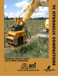
TC SERIES HYDRAULIC COMPACTORS
For Models :
TC51, TC71, TC80, TC91, TC151 & TC301
BREAKER TECHNOLOGY
OWNER’S MANUAL
CONTENTS
General ................................................. 4
TC51 Specifications .............................. 5
TC71 Specifications .............................. 6
TC80 Specifications .............................. 7
TC91S Specifications ............................ 8
TC151S / TC151SH Specifications ....... 9
TC301 / TC301H Specifications ............ 10
Hazard Alerts ........................................ 11
Sizing the Compactor ........................... 15
Typical Hydraulic Circuits ...................... 17
Installation ............................................. 20
Setting Flow & Pressure ....................... 21
Start-Up ................................................. 23
Operation .............................................. 24
Removal & Storage ............................... 27
Product Warranty .................................. 28
Bracket Options .................................... 29
TC51 Parts ............................................ 30
TC71 Parts ............................................ 32
TC80 Parts ............................................ 34
TC91S Parts ......................................... 36
TC151S Parts ....................................... 38
TC151SH Parts ..................................... 40
TC301 Parts .......................................... 42
TC301H Parts ....................................... 44
Compactor Owner’s Manual
3
GENERAL
BTI compactors are designed to mount on mini-excavators, backhoes and
excavators. BTI compactors combine impulse force, down pressure, and
vibration to work as soil compactors or pile/sheet drivers.
The compactor has 3 basic components:
• Mounting Bracket: attaches the compactor to the carrier boom and is
complete with adjustable mounting pins.
• Rubber Isolators: act as suspension between the base and the mount
& isolate the compactor forces from the carrier.
• Base: includes a hydraulic motor coupled to an eccentric, encased in
a steel housing with the base plate attached.
4
www.rockbreaker.com
TC51 SPECIFICATIONS
TC51L/FC
TC51H/FC
Impulse Force:
2,250 - 3,000 lb
1,020 - 1,360 kg
2,250 - 3,000 lb
1,020 - 1,360 kg
Oil Flow Req'd:
8 - 12 US gpm
30 - 45 l/min
12 - 18 USgpm
44 - 68 l/min
Cycles/Minute:
1,940 - 2,200
1,940 - 2,200
Hydraulic Connections:
#8 JIC Male
#8 JIC Male
Minimum Tube I.D.:
1/2"
1/2"
Operating Pressure:
1,500 - 2,200 psi
102 - 150 bar
1,500 - 2,200 psi
102 - 150 bar
Base Plate Dimension:
12.5 x 22"
317.5 x 558.5 mm
12.5 x 22"
317.5 x 558.5 mm
Compaction Area:
1.91 sq ft
0.177 sq M
1.91 sq ft
0.177 sq M
Weight:
295 lb
158 kg
295 lb
158 kg
Swivel Rotation:
N/A
N/A
Locking Positions:
N/A
N/A
Carrier Weight:
2,000 - 10,000 lb
907 - 4, 536 kg
2,000 - 10,000 lb
907 - 4, 536 kg
Compactor Owner’s Manual
5
TC71S SPECIFICATIONS
6
TC71S
TC71FC
Impulse Force:
3,300 - 5,000 lb
1,497 - 2,268 kg
3,300 - 5,000 lb
1,497 - 2,268 kg
Oil Flow Req'd:
13 - 17 US gpm
49 - 63 l/min
13 - 22 USgpm
50 - 83 l/min
Cycles/Minute:
2,020 - 2,500
2,020 - 2,500
Hydraulic Connections:
#12 JIC Male
#12 JIC Male
Minimum Tube I.D.:
¾"
¾"
Operating Pressure:
1,200 - 2,000 psi
81 - 136 bar
1,200 - 2,000 psi
81 - 136 bar
Base Plate Dimension:
15 x 26"
381 x 660 mm
15 x 26"
381 x 660 mm
Compaction Area:
2.71 sq ft
0.252 sq M
2.71 sq ft
0.252 sq M
Weight:
610 lb
277 kg
610 lb
277 kg
Swivel Rotation:
N/A
N/A
Locking Positions:
N/A
N/A
Carrier Weight:
5,500 - 15,500 lb
2,492 - 7,030 kg
5,500 - 15,500 lb
2,492 - 7,030 kg
www.rockbreaker.com
TC80 SPECIFICATIONS
Impulse Force:
5,000 - 8,200 lb
2,270 - 3,727 kg
Oil Flow Req'd:
20 - 26 US gpm
75 - 97 l/min
Cycles/Minute:
1,659 - 2,200
Hydraulic Connections:
#12 JIC Male
Minimum Tube I.D.:
¾"
Operating Pressure:
1,300 - 2,000 psi
88 - 136 bar
Base Plate Dimension:
23 x 26"
584 x 660 mm
Compaction Area:
4.15 sq ft
0.39 sq M
Weight:
969 lb
441 kg
Swivel Rotation:
Floating (Optional)
90o, 0o, 90o
Locking Positions:
Carrier Weight:
7,700 - 25,300 lb
3,500 - 11, 500 kg
Compactor Owner’s Manual
7
TC91S SPECIFICATIONS
8
Impulse Force:
5,000 - 8,200 lb
2,270 - 3,727 kg
Oil Flow Req'd:
20 - 26 US gpm
75 - 97 l/min
Cycles/Minute:
1,659 - 2,200
Hydraulic Connections:
#12 JIC Male
Minimum Tube I.D.:
¾"
Operating Pressure:
1,300 - 2,000 psi
88 - 136 bar
Base Plate Dimension:
23 x 27"
584 x 686 mm
Compaction Area:
4.3 sq ft
0.40 sq M
Weight:
Swivel Rotation:
1,130 lb
514 kg
180o
Locking Positions:
90o, 45o, 0o, 45o, 90o
Carrier Weight:
7,700 - 25,300 lb
3,500 - 11, 500 kg
www.rockbreaker.com
TC301 / TC301H SPECIFICATIONS
TC301
TC301H
Impulse Force:
16,300 - 24,300 lb
7,409 - 11,000 kg
16,300 - 24,300 lb
7,409 - 11,000 kg
Oil Flow Req'd:
35 - 43 US gpm
132 - 163 l/min
50 - 61 gpm
189 - 231 l/min
Cycles/Minute:
1,800 - 2,200
1,800 - 2,200
Hydraulic Connections:
#16 JIC Male
Minimum Tube I.D.:
1"
11/4”
Operating Pressure:
1,500 - 2,000 psi
102 - 136 bar
1100 - 1600 psi
75 - 109 bar
Base Plate Dimension:
34 x 37"
864 x 940 mm
34 x 37"
864 x 940 mm
Compaction Area:
8.74 sq ft
0.812 sq M
8.74 sq ft
0.812 sq M
Weight:
2,150 lb
978 kg
2,155 lb
980
Carrier Weight:
10
31,900 - 105,600 lb
14,500 - 48,000 kg
www.rockbreaker.com
#20 JIC Male
31,900 - 105,600 lb
14,500 - 48,000 kg
HAZARD ALERTS
Danger, Warning, and Caution are hazard alerts used in this manual and
on the compactor decals to identify hazards on or near the carrier and
compactor.
Danger - Immediate hazards, which WILL result in severe personal
injury or death if the proper precautions are not taken.
Warning - Hazards or unsafe practices, which COULD result in personal injury or death if the proper precautions are not taken.
Caution - Hazards or unsafe practices, which COULD result in product
or property damage if the proper precautions are not taken.
BTI cannot anticipate every possible circumstance that might involve a
hazard. The hazard alerts in this publication and on the product are therefore not all inclusive. If a tool, procedure, work method or operating
technique not specifically recommended by BTI is used, you must satisfy
yourself that it is safe for you and others. You should also ensure that the
compactor and carrier will not be damaged or made unsafe by the operation, maintenance or repair procedures you choose.
Compactor Owner’s Manual
11
HAZARD ALERTS
Do not operate the compactor with personnel in the immediate area of
the carrier and compactor.
Note and avoid all hazards and obstructions such as overhangs, ledges,
slide areas, electrical lines, underground cables, water mains, gas lines,
etc. When operating close to electrical lines, underground cables, water
mains or gas lines, contact the responsible authority and request assistance.
Do not operate this machine unless you have read and understood the
instructions and warnings in the Compactor Owner's Manual. Failure to
follow the instructions or heed the warnings could result in injury or
death. Proper care is your responsibility. Contact your distributor or BTI
for replacement manuals or decals.
12
www.rockbreaker.com
HAZARD ALERTS
Hydraulic fluids are under high pressure. Fluid escaping under pressure
can penetrate the skin causing serious injury. Relieve all pressure before
disconnecting hoses. Do not use your hand to check for hydraulic leaks.
If any fluid is injected into the skin, a doctor must surgically remove it
within a few hours or gangrene may set in.
Do not attempt to repair or modify the compactor unless you are a qualified service technician. Read and understand your owner's manuals.
Failure to follow the instructions or heed the warnings could result in
severe personal injury or death. Proper care is your responsibility.
Contact your distributor or BTI for replacement parts.
Some compactor components are heavy or awkward, plan carefully how
you will handle them when installing, removing, or disassembling.
Compactor Owner’s Manual
13
HAZARD ALERTS
Head
Protection
Foot
Protection
Eye
Protection
Hearing
Protection
Do not operate or service the compactor unless you are qualified.
Avoid loose fitting clothing, loose or uncovered long hair, jewelry and
loose personal articles. These can get caught in moving parts. Jewelry
may also ground a live circuit.
Know and use the protective equipment that is to be worn when operating or servicing the carrier. Hard hats, protective glasses, protective
shoes, gloves, reflector type vests and ear protection are types of equipment that may be required.
Never drive or operate any carrier while you are under the influence of
alcohol or drugs.
Consult your supervisor if you do not understand the Compactor Owner's
Manual.
14
www.rockbreaker.com
SIZING THE COMPACTOR
The compactor must be sized properly for both the carrier on which it
will be mounted and the work to be done.
Sizing the Compactor based on the Type of Work
Most applications require the soil under a road or load bearing surface to
be compacted to 95% or greater than the density of the original material
removed. This can be achieved with a compactor, provided the soil is the
correct type and moisture.
Uniform materials like clay and sand are difficult to compact. Virgin dirt,
pit run gravel, or soil with non-uniform particle size is preferred. The
moisture content in most material should be less than ten percent for best
results.
A typical production rate to compact soils to over 95% their original density;
Typical
Production Rate
Lift Sizes
TC51: 14- 22 cu yds /hr
(11 - 17 cu M/hr)
TC71: 18- 27 cu yds /hr
(14 - 21 cu M/hr)
TC80: 23- 32 cu yds /hr
(18 - 25 cu M/hr)
TC91S: 25- 35 cu yds /hr
(19 - 27 cu M/hr)
TC151S: 65- 75 cu yds/hr
(50 - 57 cu M/hr)
TC151SH: 65- 75 cu yds/hr
(50 - 57 cu M/hr)
TC301: 110- 130 cu yds/hr
(84 - 99 cu M/hr)
TC301H: 110- 130 cu yds/hr
(84 - 99 cu M/hr)
For proper compaction we recommend the following lift size;
TC51: .5- 1 foot
(0.15 - 0.3 M)
TC71: .5- 1 foot
(0.15 - 0.3 M)
TC80: 1- 2 foot
(0.3 - 0.6 M)
TC91S: 1- 2 foot
(0.3 - 0.6 M)
TC151S: 2- 3 foot
(0.6 - 0.9 M)
TC151SH: 2- 3 foot
(0.6 - 0.9 M)
TC301: 2- 4 foot
(0.6 - 1.2 M)
TC301H: 2- 4 foot
(0.6 - 1.2 M)
Using a higher depth of material may result in less than 95% compaction.
Compactor Owner’s Manual
15
SIZING THE COMPACTOR
Always use a compactor sized to the carrier. A compactor that is too
small for the carrier will damage the compactor, while a compactor too
big will damage the carrier. Ensure you have the proper installation kit
for attaching the compactor and that the carrier's hydraulic system meets
the compactor flow and pressure requirements.
The carrier that is selected to operate the compactor must have sufficient
reach to compact the deepest area of the trench or excavation. Therefore,
sizing the compactor based on the carrier size becomes the most
important factor in choosing the correct sized compactor.
BTI has assigned a 'Recommended Carrier Weight' range to each compactor. If the operating weight of the carrier falls within this range, the
carrier will safely handle this model. If the desired compactor falls outside of the recommended carrier weight range, the carrier's lifting capacity and oil flow will need to be verified to ensure a proper fit.
Provided the weight of the compactor does not exceed the maximum lifting capacity of the carrier at any position, the carrier is assumed to be
stable. On most loader backhoes and excavators, the maximum lifting
capacity is lowest when the boom is at full reach. This is the value that
must be compared to the operating weight of the compactor.
Carrier
Lifting Capacity
A required oil flow range is specified for each compactor, oil flow to the
compactor within this range is adequate for operation. However, for maximum productivity the carrier should be capable of providing the maximum required flow. Compare the maximum oil flow requirement of the
compactor with the oil flow capacity of the carrier. Remember the compactor will be operating at 1100-2100-psi (75-136 bar), therefore, oil flow
should be evaluated at the operating pressure.
Carrier
Oil Flow
Below is the Carrier Sizing Chart, outlining the recommended carrier
weight range for the compactor models.
16
www.rockbreaker.com
TYPICAL HYDRAULIC CIRCUITS
To run, a compactor needs hydraulic flow in one direction within a working pressure range. When installing the compactor the carrier hydraulic
circuit must have the following:
• The carrier must have a hydraulic circuit which will provide the
correct flow
• A switch to activate the compactor
• A circuit relief valve
Compactor Owner’s Manual
17
TYPICAL HYDRAULIC CIRCUITS
Carrier with Auxiliary Circuit
Often a carrier is equipped with an auxiliary control valve (see Figure 1),
this valve can be adjusted to provide the correct amount of oil flow to the
compactor. A pressure relief cartridge can also be installed to protect the
hydraulic components.
Make sure that oil is not routed back through the return port of this auxiliary valve. Instead, send the oil directly back to the tank, via the cooler
and filter.
If the circuit is plumbed using both ports on the auxiliary valve, the
return line should have a bleed line connected to tank, to prevent damaging pressure spikes from the returning oil.
Figure 1, Carrier with Auxiliary Circuit
18
www.rockbreaker.com
TYPICAL HYDRAULIC CIRCUITS
Carrier without Auxiliary Circuit
If the carrier does not have an auxiliary control valve (see Figure 2), a
priority flow control valve must be installed to direct oil flow from the
normal circuit to the compactor. The priority flow control valve is usually equipped with a flow adjustment and pressure relief.
These auxiliary control valves often need a check valve on the regulated
port to completely close the flow. If too much flow is divided, excess
heat is generated in which case the oil needs to be cooled.
Figure 2, Carrier without Auxiliary Circuit
Compactor Owner’s Manual
19
INSTALLATION
There is no separate pressure adjustment on the compactor.
The compactor's supply oil should be directed out the left side of the
boom and the return line back on the boom's right side. A combination of
hoses and steel tubing is recommended to keep the installation neat and
cost effective.
Hoses and tubes should be secured to the carrier boom with steel clamps.
Attaching mounting clamps or bulkhead fittings to the ends of the tubes
will prevent the tubes from sliding. Check the hoses to ensure they are
not being rubbed or pinched by other components.
BTI recommends the use of high-pressure ball valves at the outer end of
the stick where the hydraulic lines are disconnected to attach the compactor. This allows the line to be disconnected without losing too much
oil. BTI does not recommend hydraulic quick disconnects. However, if
they are installed, ensure the flush face style is used and then only on the
TC91S or smaller models.
Mounting the Compactor
Compactors are easily mounted by doing the following:
Orient the compactor with its hose connections pointed towards the carrier.
Remove the pins and bushings from the compactor top mount bracket
(Note: the compactor mounting pins and bushings are custom made to
match the carrier stick).
Insert the bushings into the boom and link of the carrier. (If Required).
Place the carrier boom into the compactor top mount bracket.
Push the pins through the bracket and boom (do not force the pins, if they
do not enter easily, try realigning).
Insert the pin retainers.
If the carrier is equipped with a Quick Attach system, ensure the device is
securely locking in position before operation.
20
www.rockbreaker.com
SETTING FLOW & PRESSURE
For a compactor to operate properly it requires a specific oil flow and
sufficient oil pressure.
TC51L/FC: 1500-2200 psi @ 8-12 USgpm
Oil Flow &
Oil Pressure
(102-150 bar) @ (30-45 l/min)
TC51H/FC: 1500-2200 psi @ 12-18 USgpm
(102-150 bar) @ (44-68 l/min)
TC71: 1200-2000 psi @ 13-17 USgpm
(81-136 bar) @ (49-63 l/min)
TC71FC: 1200-2000 psi @ 13-22 USgpm
(81-136 bar) @ (50-83 l/min)
TC80 : 1300-2000 psi @ 20-26 USgpm
(88-136 bar) @ (75-97 l/min)
TC91S: 1300-2000 psi @ 20-26 USgpm
(88-136 bar) @ (75-97 l/min)
TC151S: 1500-2000 psi @ 25-31 USgpm
(102-136 bar) @ (98-121 l/min)
TC151SH: 1100-1600 psi @ 35-43 USgpm
(75-109 bar) @ (132-163 l/min)
TC301: 1500-2000 psi @ 35-43 USgpm
(102-136 bar) @ (125-163 l/min)
TC301H: 1100-1600 psi @ 50-61 USgpm
(75-109 bar) @ (189-231 l/min)
Working
Pressure Range
To begin, connect a flow meter into the circuit in place of the compactor. Measure
the 'no-load' flow by pressing the compactor fire, which activates the control
valve and simulates the compactor working. While still activating the 'compactor'
fire, adjust the flow meter putting a load on the circuit. Adjust the flow meter
pressure until it falls within the working pressure range:
TC51L/FC: 1500-2200 psi (102-150 bar) TC51H/FC: 1500-2200 psi (102-150 bar)
Carrier
Oil Flow
TC71: 1200-2000 psi (81-136 bar) TC71FC: 1200-2000 psi (81-136 bar)
TC80: 1300-2000 psi (88-136 bar)
TC91S: 1300-2000 psi (88-136 bar)
TC151S: 1500-2000 psi (102-136 bar) TC151SH: 1100-1600 psi (75-109 bar)
TC301: 1500-2000 psi (102-136 bar) TC301H: 1100-1600 psi (75-109 bar)
Compactor Owner’s Manual
21
SETTING FLOW & PRESSURE
Now adjust the oil flow on the carrier, so the flow meter reading equals:
TC51L/FC: 8-12 USgpm (30-45 l/min) TC51H/FC: 12-18 gpm (44-68 l/min)
TC71: 13-17 USgpm (49-63 l/min) TC71FC: 13-22 gpm (49-83 l/min)
TC80: 20-26 USgpm (75-97 l/min)
TC91S: 18-24 USgpm (68-91 l/min)
TC151S: 25-31 USgpm (95-117 l/min) TC151SH: 35-43 gpm (132-163 l/min)
TC301: 35-43 USgpm (132-163 l/min) TC301H: 50-61 gpm (189-231 l/min)
To ensure the carrier's pressure relief valve does not activate while the compactor
is working, the pressure relief must be set at least 350 psi above the maximum
working pressure of the compactor.Continue to load the circuit pressure by adjusting the flow meter. Eventually the carrier's relief valve will activate and the oil
flow will drop to zero. The pressure at which the oil goes over relief will be displayed on the flow meter. If this pressure setting is at least 350 psi or greater than
the maximum working pressure of the compactor, your machine is ready. If not,
you need to adjust the carrier's pressure relief setting.
TC51 2200 + 350 psi = 2550 psi (176 + 24 = 200 bar) relief
Adjust Carrier’s
Pressure Relief
TC71 2000 + 350 psi = 2350 psi (136 + 24 = 160 bar) relief
TC80 2000 + 350 psi = 2350 psi (136 + 24 = 160 bar) relief
TC91S 2000 + 350 psi = 2350 psi (136 + 24 = 160 bar) relief
TC151S: 2000 + 350 psi = 2350 psi (136 + 24 = 160 bar) relief
TC151SH: 1600 + 350 psi = 1950 psi (109 + 24 = 133 bar) relief
TC301: 2000 + 350 psi = 2350 psi (136 + 24 = 160 bar) relief
TC301H: 1600 + 350 psi = 1950 psi (109 + 24 = 133 bar) relief
If more than one attachment with different flow requirements is to be connected
to this carrier, you will need to measure the flow and note the adjustments of
each. Mark these two locations directly on the flow control valve.
Record the oil flow and relief pressure settings when filling out the BTI
Compactor Installation Notice form.
If you are unable to obtain the proper flow when installing or adjusting the
hydraulic circuit, contact your BTI dealer for technical support.
BTI
Service Centers
Thornbury, Ontario . . .(800) 567-8267
Riverside, California . .(909) 369-0878
Solon, Ohio . . . . . . . . . (440) 248-7168
22
www.rockbreaker.com
START-UP
Carrier oil should be clean and in accordance with the manufacturer's
recommendations.
After mounting the compactor on the boom and connecting the lines,
bleed all air from the hydraulic system.
Initially pump grease to the pins in the bracket until it oozes out around
the pins. Then grease with 10-15 shots daily.
Check torque of bolts and fasteners at installation and again after the first
10 hours of operation.
Operate all boom functions to ensure clearances are good and they allow
the compactor to swivel.
Compactor Owner’s Manual
23
OPERATION
Compaction of Materials
BTI compactors achieve material compaction by using impulse force and
vibration to displace air and water pockets in the material. Compaction
performance depends on 3 items:
• Type and size of material being compacted
• Moisture content of the material
• Depths of lifts being compacted
Use a short trial of the compactor to determine the optimum depth of lift
and speed of boom travel to achieve the required density. This value will
vary depending on the material's composition and size. For example,
marbles being a uniform shape do not pack as well as gravel, which has
uneven shapes allowing the stones to interlock with each other.
Test the
Compactor First
You can reach nearly 100% of the maximum material density with a BTI
compactor by using smaller lifts, and increasing the holding time in each
spot. Typical hourly production rates to compact soil to over 95% its
original density are;
TC51L/FC / TC51H/FC: 14-22 cu yds (11-17 cu M) per hour
Hourly
Production Rates
TC71 / TC71FC: 18-27 cu yds (14-21 cu M) per hour
TC80: 23-32 cu yds (18-25 cu M) per hour
TC91S: 25-35 cu yds (19-27 cu M) per hour
TC151S / TC151SH: 65-75 cu yds (50-57 cu M) per hour
TC301 / TC301H: 110-130 cu yds (84-99 cu M) per hour
Always operate the carrier engine at the minimum speed required to
achieve the desired result. This allows the hydraulic system to run cooler.
Excess flow beyond recommended levels can damage the compactor
motor.
Operate Carrier at
Minimum Speed
Ensure the compactor base plate is in contact with the soil before operating.
Compactor Base
Must Contact Soil
When using a BTI compactor it is the amplitude (up and down motion)
of the plate, which does the compaction and not the compactor weight or
the carrier boom down-force. As you apply down-force to the compactor,
the carrier will lift slightly giving you an indication that the compactor is
properly pressed onto the material. Too much boom down-force inhibits
the up and down motion, reducing the compactor's impact force.
(Improper operation of the compactor can result in premature failure of
the rubber isolators.)
Use Proper
Boom Down-Force
24
www.rockbreaker.com
OPERATION
Shut off the compactor and lift it into the air to a new position, or using
minimum boom down-force slide the compactor along the ground. Avoid
dragging the compactor's plate across the material surface ('ironing')
while the motor is running. Forces exerted on the compactor by 'ironing'
can cause premature failure.
Working in Wet Soil
or Tight Trench
Do Not Grade
with Compactor
Keep Compactor
Parallel with Material
Initial Compacting
Another cause of premature mount failure occurs when working in very
wet soil and/or a very tight trench. Suction or drag when the compactor
is lifted can cause the mounts to tear. In these situations fasten a chain
between the compactor's upper and lower sections to relieve the lifting
strain on the rubber isolators.
Never grade the trench or level backfill with the compactor. Extreme side
forces can damage the rubber isolators.
Always keep the plate of the compactor parallel with the material being
compacted. Compactors can operate on an angle if you keep the carrier
boom down-force at 90o to the compactor base.
Start by operating the compactor in one position. Release the down force
and lift the unit to a new spot. Re-apply down-force and start compacting. Two passes are usually required. During the initial pass the compactor should be held in each position for 8-10 seconds or as long as
compaction is apparent. The second-pass should be with greater boom
down-force, focusing on areas missed during the first pass.
Compact in lift depths of:
TC51: .5-1 ft (0.15-0.3 M)
TC71: .5-1 ft (0.15-0.3 M)
Lift Depths
TC80: 1-2 ft (0.3-0.6 M)
TC91S: 1-2 ft (0.3-0.6 M)
TC151S / TC151SH: 2-3 ft (0.6-0.9 M)
TC301 / TC301H: 2-4 ft (0.6-1.2 M)
Note: using a higher material lift depth may give less than 95% soil compaction. Materials with 5% moisture give better compaction. Narrow
excavations can use higher lifts.
Compactor Owner’s Manual
25
OPERATION
When compaction is complete, shut off compactor before lifting it from
the ground.
Shut-off Compactor
Before Lifting
Do not pound the ground with the compactor.
Do not start in the middle of an un-compacted area. Always start at the
edge, near a solid wall, bank, or a previously compacted area.
Compacting Clay Materials
Clay type materials have a different composition and will not transmit
vibration as well as granular materials; therefore, it is necessary to
decrease the lift height and hold the compactor position for 15 seconds in
each spot. Two passes are usually sufficient.
Sheet or Pile Driving
Compactors are effective in driving timber sheeting, steel sheet piles, 'H'
or 'I' beams, and they drive into most soils including fine sand and rocky
O
material. Best results are achieved by keeping the compactor base 90 to
the pile and use down-force and vibration to hammer the material. If you
come across excessive resistance, lift the compactor slightly and let it
'bounce' on the pile for a hammering effect. Do not use the compactor to
extract pilings.
Cold Weather Operation
Oils for use in cold weather operation should have a viscosity not
exceeding 7500 SSU at the minimumo start up temperature. And the ambient temperature should be at least 20 F above the pour point of the oil.
Start with a gradual warm-up until the oil reaches a reasonably fluid
state.
Daily Inspection
At the end of each shift check the following:
Check rubber isolators for cracks. Replace as necessary.
Check the mounting pins and bushings for proper fit to the carrier. Check
that the pin locks are in place and secure.
Check that all hose connections are tight and there are no leaks.
If your compactor is equipped with a swivel mount, grease this connection with 5 shots dependent on the amount of compactor use.
Always use standard EP2 grease.
Check that all bolts are tight. If necessary, remove the bolt and install
using Loctite and tighten to the specified torque.
Bolt Loctite
Requirements
• Red Loctite: motor and eccentric housing bolts
• Blue Loctite: rubber isolator bolts and all others
26
www.rockbreaker.com
OPERATION
Maintenance- Every 40 Hours of Operation
Check hoses for wear and leaks, replace and tighten as required.
The eccentric housing is filled with gear oil. This oil must be changed
after the initial 50 hours. Then change oil every year. Use 80W90 gear
oil.
Do not overfill the oil reservoir.
Check the rubber isolators for cracks or fatigue. Clean away any soil and
material that has built up in this area.
Check that mounting pins and bushings are receiving lubrication.
Removal and Storage
Disconnect the pressure and return lines. Cap the lines on the machine
and on the compactor to prevent dirt from entering.
Remove pins to disconnect compactor from boom. Spread grease on pins
and bushings after removal to prevent corrosion.
Compactor Owner’s Manual
27
PRODUCT WARRANTY
1. BREAKER TECHNOLOGY Company (hereinafter referred to as BTI) warrants this product against defects in materials and workmanship for a period of
twelve (12) months from the date of installation. This warranty does not cover
o-rings, seals, fittings, hoses, or other items considered normal wear items.
These are covered by the Limited Warranty period of thirty (30) days. Warranty
for propriety items such as valves, filters, installation kits, and componentry that
are not manufactured by BTI, will be governed by the warranty terms of their
manufacturer. This warranty is void if BTI's standard installation specifications
and procedures are not adhered to.
2. BTI's Customer Service Department will authorize return of any defective
components or sufficient evidence of such defect to a BTI warehouse. Such
components or such evidence must clearly show that the defect was caused by
faulty material or poor workmanship. Warranty claim will be accepted only if it
is submitted on a proper claims form with proof of purchase and received within
sixty (60) days from the date of discovery of the defect. Warranty claims will be
considered only if the "Installation Notice" has been duly filled in and returned
to BTI's Customer Service Department within thirty (30) days from the date of
installation.
3. BTI will at it's option, repair or refurbish the defective part(s) without charge
to the initial user or may elect to issue full or partial credit toward the purchase
of a new part(s). The extent of credit issued, which will be in the form of a
"Credit Memo", will be determined by pro-rating against the normal life of the
part(s) in question.
4. BTI is not responsible for mileage, travel time, travel expenses, overtime
labor, and any freight expenses required to facilitate the repair.
5. This warranty does not apply if the product has been damaged by accident,
abuse, misuse, misapplication or neglect, or as a result of service, disassembly
or modification, without BTI's express authorization.
6. BTI assumes no liability beyond the replacement of defective parts or materials and/or the correction of such defective parts or materials.
7. BTI neither assumes nor authorizes any other person to assume for it any liability in connection with the sale of it's products other than that specifically stated herein.
8. THIS WARRANTY IS EXPRESSLY IN LIEU OF ANY AND ALL OTHER
WARRANTIES.
EXCEPT AS EXPRESSLY SET FORTH HEREIN, BTI MAKES NO REPRESENTATION OR
WARRANTY, STATUTORY, EXPRESS OR IMPLIED, WITH RESPECT TO
THE PRODUCTS
MANUFACTURED AND/OR SUPPLIED BY BTI, WHETHER AS TO MERCHANTABILITY, FITNESS FOR A PARTICULAR PURPOSE OR ANY
OTHER MATTER. IN NO EVENT, INCLUDING IN THE CASE OF A
CLAIM OF NEGLIGENCE, SHALL BTI BE LIABLE FOR INCIDENTAL OR
CONSEQUENTIAL DAMAGES.
28
www.rockbreaker.com
BRACKET OPTIONS
Bolt-On Rigid Top Mount:
(Shown on TC80)
Standard equipment on TC51,
TC71, TC80 & TC301
Bolt-On QA Non-Swivel
Top Mount:
Available as an option on the
TC71 & TC80
QA Swivel Top Mount:
Standard equipment on TC91S &
TC151S. Optional Bolt-On on the
TC71 and TC80.
Compactor Owner’s Manual
29
TC51
TC51 PARTS
When ordering give Part Number, Part Name, Model and Serial #.
30
www.rockbreaker.com
TC51 PARTS
NOTE:
For Mounting
Bracket options and
parts information
contact BTI.
Item
Part Number
Description
Qty.
1
2
3
4
5
6
7
8
9
10
11
12
13
14
15
16
17
18
19
20
21
350-0007
1800424*
9006862
650-8780
350-0002
650-8795
1008414
1008453
650-8796
1800288
1009488
1912007
1001856
1008798
1911113
1001856
1912270
1941002
1009487
1932008
H05-KKK-023*
350-0110*
Upper Weldment
Cap
Fill/Drain
Bearing Housing
Lower Weldment
Eccentric Assembly
Bearing
Retaining Ring
Bearing Housing
Fitting
Hydraulic Motor
Bolt - Grade 8
Nordlock Washer Set
Gasket
Bolt - Grade 5
Nordlock Washer Set
Button Head Cap Screw
Flat Washer
Isolator
Locknut
Hose Assembly
Motor Repair Kit
1
2
1
1
1
1
2
2
1
2
1
2
2
1
8
8
32
64
4
32
2
REF
350-1002
350-0103
Low Flow Kit (L/FC) - 9.0 gpm
High Flow Kit (H/FC) - 13.5 gpm
* Not Shown
Compactor Owner’s Manual
31
TC71
TC71 PARTS
When ordering give Part Number, Part Name, Model and Serial #.
32
www.rockbreaker.com
TC71 PARTS
NOTE:
For Mounting
Bracket options and
parts information
contact BTI.
Item
Part Number
Description
Qty.
1
2
3
4
5
6
7
8
9
10
11
12
13
14
15
16
17
18
19
20
21
22
23
24
25
360-0002
1008925
220-2708
1912271
1932014
1941004
360-0003
220-2713
1008936
1008935
1800849
220-2707
1912009
1001856
1008798
1801470
1800288
1009505
1912128
1001857
1800255
1800418*
H409-KKK-025*
H412-KKK-030*
360-0110
Upper Body
Isolator
Bearing Housing
Bolt - Grade 8
Locknut
Flat Washer
Lower Housing
Eccentric Assembly
Bearing
Reatining Ring
O-Ring
Bearing Housing - Motor Side
Bolt - Grade 8
Nordlock Washer Set
Gasket
Plug
Fitting
Hydraulic Motor
Bolt - Grade 8
Nordlock Washer Set
Fitting
Fitting - Not Shown
Hose Assembly
Hose Assemvly
Motor Repair Kit
1
4
1
32
32
34
1
1
2
2
2
1
2
2
1
1
2
1
4
4
2
2
1
1
REF
360-0101
Flow Control Kit
* Included in Hydraulic Kit
P/N 360-0100.
Compactor Owner’s Manual
33
TC80
TC80 PARTS
When ordering give Part Number, Part Name, Model and Serial #.
34
www.rockbreaker.com
TC80 PARTS
Item
NOTE:
For Mounting
Bracket options and
parts information
contact BTI.
1
2
3
4
5
6
7
8
9
10
11
12
13
14
15
16
17
18
19
20
21
22
23
Part Number
Description
Qty.
370-0007
1008925
1912261
1941004
1932014
H409-KKK-021
1800289
650-8641
1009833
1912020
1801983
650-8619
1801982
1001531
1007793
650-8618
H409-KKK-029
370-0005
1801470
650-8620
1800255
1800418
370-0110
Top Mount
Top Frame Weldment
Isolator
Bolt
Washer
Locknut
Hose Assembly
Fitting
Stud
Motor
Hex Head Bolt
O-Ring
Bearing Housing
O-Ring
Bearing
Retaining Ring
Eccentric Assembly
Hose Assembly
Drum Weldment
Plug
Bearing Housing
Fitting
Fitting
Motor Repair Kit
REF
1
4
32
64
32
1
2
4
1
8
1
1
2
2
2
1
1
1
1
1
1
1
REF
Compactor Owner’s Manual
35
TC91S
TC91S PARTS
When ordering give Part Number, Part Name, Model and Serial #.
36
www.rockbreaker.com
TC91S PARTS
NOTE:
For Mounting
Bracket options and
parts information
contact BTI.
Item
Part Number
Description
Qty.
1
2
3
4
5
6
7
8
9
10
11
12
13
14
15
16
17
19
20
25
26
27
28
29
33
34
35
36
37
38
40
44
45
46
47
48
49
50
52
54
1912048
1801016
1941015
650-5569
1001534
Bolt
Grease Fitting 1/8” NPT
Flatwasher
Cap Flange
Top Bearing Washer
Bushing - Contact BTI for Part #
Bushing
Top Mount Weldment
Bottom Bearing Washer
Nordlock Washer Set M12
Bolt 1/2” -13UNC x 1 1/2” LG GR8
Pin - Contact BTI for Part #
Quick Pin c/w Chain
Clevis Pin
Frame Weldment
Fitting
Cap
Fitting
Quick Pin
Bearing Housing
Pipe Plug
O-Ring
Bearing
Retaining Ring
Eccentric Assembly
Lattice Mount (includes 35, 38, 40)
Nordlock Washer Set M20
Locknut 3/4” NC
Base Plate Weldment
Stud
Hex Nut 3/4” NF
Bearing Housing
External Retaining Ring
O-Ring
Fitting
Hose Assembly
Hydraulic Motor
Stud
Locknut 1/2” -20UNF
Hose Assembly
Decal Kit
Motor Repair Kit
14
1
14
1
1
REF
1
1
1
44
40
REF
4
1
1
1
2
1
1
2
2
2
2
2
1
2
20
8
1
12
12
1
1
1
2
1
1
4
4
1
REF
REF
1001535
650-8501
1001536
1001857
1912020
1002184
650-8296
650-8617
1800261
1800418
1800255
1001529
650-8620
1801020
1801982
1001531
1007793
650-8618
650-8710
1001858
1932020
650-8616
650-8676
1931013
650-8619
1007794
1801983
1800289
H405-KKK-014
1009833
650-8641
1932015
H405-KKK-022
650-8622
370-0110
Compactor Owner’s Manual
37
TC151S
TC151S PARTS
When ordering give Part Number, Part Name, Model and Serial #.
38
www.rockbreaker.com
TC151S PARTS
Item Part Number
NOTE:
For Mounting
Bracket options and
parts information
contact BTI.
1
2
3
4
5
6
7
8
9
10
11
12
13
14
15
17
18
20
21
22
23
24
25
26
27
28
29
31
32
33
34
36
38
42
43
44
45
46
47
50
51
54
Description
Bolt
Grease Fitting 1/8” NPT
Flatwasher
Cap Flange
Mounting Bracket - Contact BTI
Top Bearing Washer
1001534
Bushing
1001535
Pin
700-0225
Quick Pin c/w Chain
1002184
Bottom Bearing Washer
1001536
Clevis Pin
650-8296
Frame Weldment
650-8587
Fitting
1800419
Fitting
1800262
Quick Pin
1001529
Fitting
1801223
Bolt 3/4” NC x 3”LG GR.8
1912086
Bolt 5/8” NC x 1 1/2” GR.8
1912138
Nordlock Washer Set
1001768
Bearing Housing
650-8592
Pipe Plug
1801020
O-Ring
1801980
Bearing
1002182
Retaining Ring Internal
1007783
Eccentric Assembly
650-8589
Fitting
1800102
H06-GGG-010 Hose Assembly
Lattice Mount (Includes 32,36,38)
650-8710
Nordlock Washer Set M20
1001858
Locknut 3/4” NC
1932020
Base Plate
650-8586
Stud
650-8676
Hex Nut 3/4” NF
1931013
H408-LLL-026 Hose Assembly
Fitting
1800943
O-Ring
1800947
Hydraulic Motor
1009834
Bolt 1/2” NF x 1/4” GR.8
1912097
Nordlock Washer Set M12
1001857
H405-LLL-026 Hose Assembly
Retaining Ring
1007784
Bearing Housing Motor Side
650-8593
Decal Kit
650-8591
Motor Repair Kit
380-0110
1912048
1801016
1941015
650-5569
Compactor Owner’s Manual
Qty.
6
1
14
1
1
1
1
2
4
1
1
1
2
2
1
2
8
8
8
1
2
2
2
2
1
2
1
2
20
8
1
12
12
1
2
1
1
4
4
1
1
1
REF
REF
39
TC151SH
TC151SH PARTS
40
www.rockbreaker.com
TC151SH PARTS
Item Part Number
NOTE:
For Mounting
Bracket options and
parts information
contact BTI.
1
2
3
4
5
6
7
8
9
10
11
12
13
14
15
17
18
20
21
22
23
24
25
26
27
28
29
31
32
33
34
36
38
42
43
44
45
46
47
50
51
54
Description
Bolt
Grease Fitting 1/8” NPT
Flatwasher
Cap Flange
Mounting Bracket - Contact BTI
Top Bearing Washer
1001534
Bushing
1001535
Pin
700-0225
Quick Pin c/w Chain
1002184
Bottom Bearing Washer
1001536
Clevis Pin
650-8296
Frame Weldment
650-8587
Fitting
1800419
Fitting
1800262
Quick Pin
1001529
Fitting
1801223
Bolt 3/4” NC x 3”LG GR.8
1912086
Bolt 5/8” NC x 1 1/2” GR.8
1912138
Nordlock Washer Set
1001768
Bearing Housing
650-8592
Pipe Plug
1801020
O-Ring
1801980
Bearing
1002182
Retaining Ring Internal
1007783
Eccentric Assembly
650-8589
Fitting
1800102
H06-GGG-010 Hose Assembly
Lattice Mount (Includes 32,36,38)
650-8710
Nordlock Washer Set M20
1001858
Locknut 3/4” NC
1932020
Base Plate
650-8586
Stud
650-8676
Hex Nut 3/4” NF
1931013
H408-LLL-026 Hose Assembly
Fitting
1800292
O-Ring
1800947
Hydraulic Motor
1009835
Bolt 1/2” NF x 1/4” GR.8
1912097
Nordlock Washer Set M12
1001857
H405-LLL-026 Hose Assembly
Retaining Ring
1007784
Bearing Housing Motor Side
650-8593
Decal Kit
650-8591
Motor Repair Kit
380-0110
1912048
1801016
1941015
650-5569
Compactor Owner’s Manual
Qty.
6
1
14
1
1
1
1
2
4
1
1
1
2
2
1
2
8
8
8
1
2
2
2
2
1
2
1
2
20
8
1
12
12
1
2
1
1
4
4
1
1
1
REF
REF
41
TC301
TC301 PARTS
When ordering give Part Number, Part Name, Model and Serial #.
42
www.rockbreaker.com
TC301 PARTS
NOTE:
For Mounting
Bracket options and
parts information
contact BTI.
Item
Part Number
Description
Qty.
1
2
3
4
5
6
7
8
9
10
11
12
13
17
19
22
24
25
26
29
31
33
34
35
390-0002
1800262
1800419
1001858
1912046
650-8526
1801020
1801855
1006886
1006919
650-8527
650-8679
1801223
650-8525
1006920
1009835
1800292
H405-LLL-033
1800947
1932052
1007828
1911185
1912097
1001857
650-8683
380-0110
Top Weldment
Fitting
Fitting
Nordlock Washer Set M20
Bolt 3/4” -10UNC x 2 1/2” GR.8
Bearing Housing
Pipe Plug
O-Ring
Spherical Roller Bearing
Retaining Ring
Eccentric Assembly
Base Weldment
Fitting
Bearing Housing
Retaining Ring
Hydraulic Motor
Fitting
Hose Assembly
O-Ring
Locknut
Rubber Mount
Bolt 3/4” NC x 2 3/4” GR.5
Bolt 1/2” -20 UNF x 1 1/2” GR.5
Nordlock Washer Set M12
Decal Kit
Motor Repair Kit
1
2
2
72
8
1
2
2
2
2
1
1
2
1
1
1
2
2
1
32
4
32
4
4
REF
REF
Compactor Owner’s Manual
43
TC301H
TC301H PARTS
44
www.rockbreaker.com
TC301H PARTS
NOTE:
For Mounting
Bracket options and
parts information
contact BTI.
Item
Part Number
Description
Qty.
1
2
3
4
5
6
7
8
9
10
11
12
13
17
19
22
24
25
26
29
31
33
34
35
650-8680
1801591
1800420
1001858
1912046
650-8526
1801020
1801855
1006886
1006919
650-8527
650-8679
1801223
650-8525
1006920
1009836
1800294
H405-MMM-033
1800947
1932052
1007828
1911185
1912097
1001857
650-8683
390-0110
Top Weldment
Fitting
Fitting
Nordlock Washer Set M20
Bolt 3/4” -10UNC x 2 1/2” GR.8
Bearing Housing
Pipe Plug
O-Ring
Spherical Roller Bearing
Retaining Ring
Eccentric Assembly
Base Weldment
Fitting
Bearing Housing
Retaining Ring
Hydraulic Motor
Fitting
Hose Assembly
O-Ring
Locknut
Rubber Mount
Bolt 3/4” NC x 2 3/4” GR.5
Bolt 1/2” -20 UNF x 1 1/2” GR.5
Nordlock Washer Set M12
Decal Kit
Motor Repair Kit
1
2
2
72
8
1
2
2
2
2
1
1
2
1
1
1
2
2
1
32
4
32
4
4
REF
REF
Compactor Owner’s Manual
45
SOLON FACILITY
30625 Solon Industrial Drive,
SOLON OHIO,
44139 U.S.A.
PH. 440-542-3720
FAX. 440-542-3721
RIVERSIDE FACILITY
3464 DURAHART ST.
RIVERSIDE,CALIF.
92507 U.S.A.
PH. 909-369-0878
FAX. 909-369-8281
THORNBURY FACILITY
35 ELGIN ST.,
THORNBURY,ONT.
N0H 2P0 CANADA
PH. 519-599-2015
FAX. 519-599-6803