1
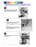
MAGICARD PRINTER
INSTRUCTIONS FOR REPLACEMENT OF
PRINTHEAD AND PRINTHEAD ASSEMBLIES
WARNING - The Magicard colour printer contains hazardous voltages.
CAUTION - The following procedures involve contact with Electrostatic Sensitive
Devices. All Precautions for handling Electrostatic Sensitive Devices should be
followed at all times, including the use of a grounded wrist strap.
HOW TO USE THESE
INSTRUCTIONS
The following procedures are intended to be used for replacement of
Thermal Printheads and Magicard Thermal Printhead Assemblies.
Magicard
If replacing a Thermal Printhead Assembly do NOT carry out those parts of this
document written in italics . These procedures, for head angle adjustment, require some
previous Magicard product training or experience, and must not be undertaken by end
users. Therefore end users are supplied with replacement Printhead Assemblies, which
have already been adjusted for correct head angle.
3461/07/01 ISSUE 2
PRINTHEAD INSTALLATION & COMMISSIONING SPEC.
I
DCR No. 26106
1.
(a) Removing the cover
Magicard 300 and Sprinter models.
(1) Set the printer On/Off switch to off(0) and isolate from the mains supply. Remove the
card cassette and Dye-Film from the
printer.
(2) Position the printer on its side with the
rear of the printer facing towards you
and remove the five securing screws
from the base of the printer plus the
two at the rear of the printer.
(3) Place the printer on its base with the front
of the printer facing towards you.
(4) Lift the printer cover from the rear and
carefully remove it from the printer
taking care not to strain the ribbon cable
connection from printer circuit board
PL8, and place the cover aside.
3461/07/01 ISSUE 2
PRINTHEAD INSTALLATION & COMMISSIONING SPEC.
II
DCR No. 26106
1.
(b) Removing the cover
Magicard Turbo models.
(1) Set the printer On/Off switch to Off(O) and isolate from the mains supply. Remove the
card cassette and the Dye-Film from
the printer.
(2) Position the printer upside down
with the rear of the printer facing
towards you and remove the four
securing screws from the base of the
printer plus the eight at the rear of
the printer.
(3) Position the printer with the front panel
facing upwards. Remove the two screws from
the underside of the front panel and remove the
two screws from the top left and top right of the
front panel.
(4) Turn the printer back onto its base and
lift off the front cover. Using an M4
spanner loosen the bolt at the right hand
end of the Door Locking Shaft and
disconnect the operating lever from the
shaft.
(5) Flex out the sides of the cover and lift it
carefully away.
3461/07/01 ISSUE 2
PRINTHEAD INSTALLATION & COMMISSIONING SPEC.
III
DCR No. 26106
2. Removing old printhead/assembly
(1) Remove the dye-film and
dye-film carrier from the
printer.
(2) If a tye-wrap is fitted to the
grey ribbon cable plug on the
back of the printhead, cut this
tye-wrap taking great care not
to cut the ribbon cable itself.
(3) Disconnect both cables from
the printhead.
(4) If a head bar is fitted, remove the securing
screw at each end and lift away the head bar.
This should leave the earthing strap loose at the
right hand side of the chassis cover.
If no head bar is fitted, disconnect the earthing
strap from the reatining screw at the left hand
side ot the printhead assembly
(5) Disengage the two lugs at the ends of the
two nylon side brackets by spreading apart the
legs of the nylon brackets until the lugs just
clear the chassis cover, swing them forwards
and allow them to rest against the leading edge
of the chassis cover.
N.B. Before removing the printhead
assembly completely from the printer,
take careful note of how the two
springs are attached at the rear and
each side of the assembly.
(6)Using both hands, hold the
printhead assembly at each side by
the nylon brackets, and move it
upwards. Note : as the assembly
disengages from the chassis cover,
the two springs will push it forwards
and care must be taken not to lose
the springs as the printhead is lifted
clear.
(7)Place the printhead assembly on a bench with the printhead and its labels at the bottom.
Undo and remove the printhead pivot screw (see diagram) and its two washers .
(8)Slide the printhead backwards (plugs first) out of the heatsink.
3461/07/01 ISSUE 2
PRINTHEAD INSTALLATION & COMMISSIONING SPEC.
IV
DCR No. 26106
3. Fitting the new printhead to the heatsink
assembly (Magicard Dealers Only)
CAUTION - The following procedures involve contact with the new printhead, all
precautions for handling Electrostatic Sensitive Devices should be followed at all times,
including the use of a grounded wrist strap. Furthermore great care must be taken not to
touch or damage the printing elements of the printhead.
(1) Ensure that the brass backing plate attached to new printhead has a very thin, evenly
spread film of graphite grease over its surface.
(2) Apply a very small amount of Loctite 242 Threadlocker to the hole in the brass backing
plate into which the printhead pivot screw will shortly be inserted .
(3) With the heatsink still in position on the bench, slide in the new printhead until the two
pivot screw holes are aligned and insert the pivot screw with its washers (thin crinkly
washer closest to the head of the screw).
(4) Great care must now be taken to ensure
that this pivot screw is not over tightened
- it must be set loosely enough such that
the printhead can swivel freely about the
axis of the screw (see diagram right) but
not so loose that, with a little pressure,
any gap can be made between heatsink,
and the printhead with its backing plate
(see diagram below).
4. Fitting the new printhead assembly into
the printer
(1) Offer up the printhead assembly to its position in the chassis cover ensuring that the
earthing strap is routed to outside of the chassis cover and, whilst holding in position,
ensure that the ends of each spring are correctly located on the lugs on the chassis
cover. Compress the springs by pushing the printhead assembly backwards and
downwards against the chassis cover, and the printhead assembly should slot into
place.
(2) Now engage the two lugs at the bottom of the printhead assembly nylon side brackets
by bending them outwards slightly and swinging them backwards until the lugs locate
in the holes in the chassis cover.
3461/07/01 ISSUE 2
PRINTHEAD INSTALLATION & COMMISSIONING SPEC.
V
DCR No. 26106
(3) Check that the springs at the back of the printhead assembly are neatly compressed and
are not bulging outwards or inwards. If they are bulging the assembly will have to be
removed and refitted again until they remain neatly compressed.
(4) If a head bar was fitted, refit it with its two securing screws ensuring that the left hand
screw is also fitted through the terminal of the printhead earthing strap (Loctite 222
threadlocker should be used on these screws). Align the terminal downwards and in
parallel with the leading edge of the chassis cover.
If no head bar was fitted, ensure that the printhead earthing strap is connected to its’
original securing point
(5) Reconnect the two cables at the rear of the printhead ensuring that the locking arms of
the grey ribbon cable connector are fully engaged.
(6) Referring to the rear of the Test Card which was supplied with your new printhead, set
the ‘density hex value’ as
indicated on the rear of the
card.
N.B. There are two different
diagrams on the rear of the
card (see right), compare the
cicuit board in your printer
against the two diagrams and
decide which diagram is
relevent to your printer.
Then change the settings on
your printer to match those
marked on the diagram on
your card (in the high-lighted area). Do not change any of the unmarked switch
positions.
5. Refitting the cover
Refitting of the case is the reverse of removal.
Ensure the printer interior is free of debris or particles.
Take care not to trap the display cable as the top cover is lowered into position.
6. Setting up your new thermal printhead
(1) Load the card cassette with cards and refit into the printer.
On Flip models ensure that UR8 Dye-Film is fitted.
On all other models fit UR1 Dye-Film.
(2) Reconnect the mains supply and switch on the printer.
(3) After the printer has finished its initialisation sequence (all lights have stopped
flashing and the printer is silent), press the internal test button at the rear of the printer
(approx 1cm above the Centronics port). After a short delay the printer will start to
print a test image.
3461/07/01 ISSUE 2
PRINTHEAD INSTALLATION & COMMISSIONING SPEC.
VI
DCR No. 26106
(4) The printhead angle has been factory set. In order to ensure that it is still correct,
compare the test card with the images on the back page of this document.
N.B. If your test card shows a completely different test image from those on the back
page, you will need to download the correct test image from the Ultra website at
www.ultra.co.uk/support . This image can then be printed from any paint package on your
PC.
(5) If the printhead angle requires adjustment take note of the current position of the
printhead angle adjustment screws (at the upper rear corner on each nylon side
bracket).
NOTE : There are now two different types of nylon side brackets – one with 7 adjustment
holes and one with 9 adjustment holes (see diagrams below).
(6)With reference to the relevant diagram (below) and the diagram on the rear page,
decide which of the adjustment holes that the screws need to be moved to.
(7)Remove both printhead angle adjustment screws and raise or lower the rear of the
printhead in order to align the required hole in the nylon bracket with the inner hole of
the brass heatsink, and fit and tighten the two printhead adjustment screws.
NOTE : If a printhead angle adjustment screw is moved to a different hole then the other
screw must be moved to the corresponding hole on the other side of the printhead
assembly.
(8) Steps (3) to (7) should be repeated until the optimum printhead angle is obtained.
TWO TYPES OF NYLON SIDE BRACKETS
3461/07/01 ISSUE 2
PRINTHEAD INSTALLATION & COMMISSIONING SPEC.
VII
DCR No. 26106
7. And finally.....
If your new thermal printhead fails to produce a good test image after following the above
steps then please contact your supplier.
Too Positive
Dark patches stressing
out from the rear edge
of the green square
(watermarking). These
patches have many
jagged edges. Plus
possibly a dark patch at
the front of the grey
square,.
SOLUTION: Decrease
head angle by 1 or 2
degrees.
Correct Head Angle
Uniform density across the whole of the grey
square, with no marks or defects in the green
square.
Too Negative
Front or most of the grey
square is pale and washed
out. Density can suddenly
increase in the last third of
the square.
SOLUTION: Increase head
angle by 1 or 2 degrees.
3461/07/01 ISSUE 2
PRINTHEAD INSTALLATION & COMMISSIONING SPEC.
VIII
DCR No. 26106