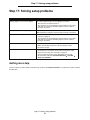
1
4600 MFP Option
Printer and Scanner
Setup Guide for the
C782n printer
February 2007
www.lexmark.com
Stability Information
CAUTION: Certain floor-mounted configurations require additional furniture for stability. More information is available
on our Lexmark Web site at www.lexmark.com/multifunctionprinters.
2
3
English
Edition: February 2007
The following paragraph does not apply to any country where such provisions are inconsistent with local law: LEXMARK
INTERNATIONAL, INC., PROVIDES THIS PUBLICATION “AS IS” WITHOUT WARRANTY OF ANY KIND, EITHER EXPRESS OR
IMPLIED, INCLUDING, BUT NOT LIMITED TO, THE IMPLIED WARRANTIES OF MERCHANTABILITY OR FITNESS FOR A PARTICULAR
PURPOSE. Some states do not allow disclaimer of express or implied warranties in certain transactions; therefore, this statement may not
apply to you.
This publication could include technical inaccuracies or typographical errors. Changes are periodically made to the information herein; these
changes will be incorporated in later editions. Improvements or changes in the products or the programs described may be made at any
time.
Comments about this publication may be addressed to Lexmark International, Inc., Department F95/032-2, 740 West New Circle Road,
Lexington, Kentucky 40550, U.S.A. In the United Kingdom and Eire, send to Lexmark International Ltd., Marketing and Services
Department, Westhorpe House, Westhorpe, Marlow Bucks SL7 3RQ. Lexmark may use or distribute any of the information you supply in
any way it believes appropriate without incurring any obligation to you. To obtain additional copies of publications related to this product, visit
the Lexmark Web site at www.lexmark.com.
References in this publication to products, programs, or services do not imply that the manufacturer intends to make these available in all
countries in which it operates. Any reference to a product, program, or service is not intended to state or imply that only that product,
program, or service may be used. Any functionally equivalent product, program, or service that does not infringe any existing intellectual
property right may be used instead. Evaluation and verification of operation in conjunction with other products, programs, or services, except
those expressly designated by the manufacturer, are the user’s responsibility.
Conventions
Note: A note identifies something that could help you.
CAUTION: A caution identifies something that could cause you harm.
Warning: A warning identifies something that could damage your product hardware or software.
Trademarks
Lexmark, Lexmark with diamond design, and StapleSmart are trademarks of Lexmark International, Inc., registered in the United States
and/or other countries.
Details relating to compatibility are included in the Technical Reference.
Other trademarks are the property of their respective owners.
© 2006 Lexmark International, Inc.
All rights reserved.
UNITED STATES GOVERNMENT RIGHTS
This software and any accompanying documentation provided under this agreement are commercial computer software and documentation
developed exclusively at private expense.
Safety information
CAUTION:Use only a 26 AWG or larger telecommunications (RJ-11) cord when connecting this product to the
public switched telephone network.
CAUTION: Refer service or repairs, other than those described in the operating instructions, to a professional service
person.
CAUTION: This product is designed, tested, and approved to meet strict global safety standards with the use of specific
Lexmark components. The safety features of some parts may not always be obvious. Lexmark is not responsible
for the use of other replacement parts.
CAUTION: Make sure that all external connections (such as Ethernet and telephone system connections) are properly
installed in their marked plug-in ports.
5
CAUTION: This product uses a laser.
Use of controls or adjustments or performance of procedures other than those specified herein may result in
hazardous radiation exposure.
CAUTION: This product contains mercury in the lamp (<5mg Hg). Disposal of mercury may be regulated due to
environmental considerations. For disposal or recycling information, contact your local authorities or the
Electronic Industries Alliance: www.eiae.org.
CAUTION: The printer weighs 48–82 kg (105–181 lb). It requires at least three (3) people to lift it safely. Use the printer
handholds to lift it, do not lift by the front of the printer, and make sure your fingers are not under the printer when
you set it down.
CAUTION: If you are installing options after setting up the printer, turn the printer off, and unplug the power cord from the
wall outlet before continuing.
CAUTION: If you are installing memory or option cards sometime after setting up the printer, turn the printer off, and unplug
the power cord from the wall outlet before continuing.
CAUTION: Connect the power cord to a properly grounded electrical outlet that is near the product and easily accessible.
Do not use the fax feature during a lightning storm. Do not set up this product or make any electrical or cabling
connections, such as the power cord or telephone, during a lightning storm.
Static sensitivity notice
Warning: This symbol identifies static-sensitive parts. Do not touch in the areas near these symbols without first
touching the metal frame of the MFP.
6
Overview
Overview
MFP configurations
Printer stand configuration
Scanner cabinet configuration
Note: Do not use a printer stand with a
configured stack containing a
2000-sheet, high-capacity drawer.
Note: Do not place a scanner shelf on top of a
configured stack containing a 2000-sheet,
high-capacity drawer.
Scanner
Scanner
Scanner shelf
Printer
Scanner cabinet
Duplex unit
Envelope drawer
500-sheet drawer
Printer stand
2000-sheet drawer
Turning off the printer
If you are installing a scanner after initial printer setup, turn the printer off, and unplug the power cord from both the wall
outlet and the printer or the 2000-sheet drawer. If you have other devices connected to the printer, turn them off as well, and
unplug all power cords.
Note: Leave the printer and MFP in the box until you are ready to assemble them.
Selecting a location for your printer and MFP
CAUTION: The printer weighs 48–82 kg (105–181 lb). It requires at least three (3) people to lift it
safely. Use the printer handholds to lift it, do not lift by the front of the printer, and make sure your fingers
are not under the printer when you set it down.
When selecting a location for your printer and MFP option, you must leave enough room to open the printer trays, covers,
doors, and MFP option. It is also important to:
•
Allow space around the printer for proper ventilation.
•
Provide a firm, level, and stable surface.
Overview
7
Overview
•
Keep the equipment away from the direct airflow of air conditioners, heaters, or ventilators.
•
Keep the equipment free of sunlight, humidity extremes, or temperature fluctuations.
•
Keep the equipment clean, dry, and free of dust.
Customizing your MFP option
You can customize your MFP with various input, output, and memory options.
Note: Leave all components and hardware in the boxes until you are ready to install them.
Check the boxes you received to make sure you have all the necessary components for the configuration you ordered.
CAUTION: If you are installing options after setting up the printer, turn the printer off, and unplug the
power cord from the wall outlet before continuing.
The following options are available for your MFP.
Input options
Output options
Other options
500-sheet drawer
Output expander
Duplex unit
2000-sheet drawer
5-bin mailbox
Scanner shelf
Envelope drawer
StapleSmart™ finisher
Printer stand
100-sheet outdoor media drawer
Scanner cabinet
CAUTION: Certain floor-mounted configurations require additional furniture for stability. More
information is available on our Lexmark Web site at www.lexmark.com/multifunctionprinters.
Note: Follow the steps in the order presented. If you do not have the option listed in a step, skip that step
and continue with the next one. Unless other instructions are indicated in a step, see the installation
setup instructions that came with the option.
Customizing your MFP option
8
Step 1: Setting up furniture
Step 1: Setting up furniture
If you purchased your scanner as a bundle (printer shipped with: a duplex unit, two 500-sheet drawers, a scanner, a
scanner shelf, and a printer stand), or you purchased your scanner with optional furniture and/or drawers, set up your
printer starting with the printer stand or scanner cabinet.
Note: Place the furniture in the location you are assembling your printer and follow the instructions that
came with the furniture.
Printer stand assembly
Scanner cabinet setup
Step 1: Setting up furniture
9
Step 2: Installing optional drawers
Step 2: Installing optional drawers
Note: Do not place a scanner shelf on top of a configured stack containing a 2000-sheet, high-capacity
drawer.
Note: Do not use a printer stand with a configured stack containing a 2000-sheet, high-capacity drawer.
If you are installing a 2000-sheet drawer, install it before any other optional drawer. Follow the installation setup instructions
that came with each drawer, and then go to Step 3 to install the duplex unit.
If you are using a printer stand refer to the chart below:
MFP
Total number of additional 500-sheet drawers allowed
with or without a duplex unit*
1
2
3
Yes
Yes
No
*The duplex unit must be installed directly under the printer in any configuration. All other drawers must be
installed under the duplex unit.
Step 3: Installing the duplex unit
If you installed optional drawers, they must be installed below the duplex unit. The duplex unit must be installed directly
under the printer. Follow the installation setup instructions that came with the duplex unit, and then go to Step 4.
Step 4: Unboxing the printer
Remove the printer from the box, and then remove all packaging from the printer. Follow Steps 1 and 2 of the printer setup
sheet that came with the printer, and then go to Step 5.
Step 2: Installing optional drawers
10
Step 5: Preparing the printer
Step 5: Preparing the printer
Removing the print cartridge packaging
Note: If you are installing a scanner after initial printer setup, the print cartridge packaging has already been
removed.
1
Remove all exterior packing tape.
2
Open the front door.
3
Remove and discard the packing strips.
Step 5: Preparing the printer
11
Step 5: Preparing the printer
4
Remove and discard the tabs from the cartridges.
5
Lift up, and then pull out to remove each toner cartridge.
6
Place all toner cartridges on a clean, flat surface.
7
Remove the image transfer unit (ITU) detentioner and protective cover.
Removing the print cartridge packaging
12
Step 5: Preparing the printer
8
Shake each toner cartridge front to back and side to side.
9
Remove each toner cartridge cover.
Warning: Do not touch the photoconductor.
10
Reinsert the toner cartridges into the printer.
Each toner cartridge will drop down and snap into place.
11
Close the front cover.
Removing the print cartridge packaging
13
Step 5: Preparing the printer
Loading paper
Complete these instructions to load paper into any of the standard or optional trays. All trays are loaded in the same way.
1
Remove the tray.
2
Adjust the length and width guides to the correct position for the size of paper you are loading.
3
Flex the sheets of paper back and forth to loosen them, and then fan them.
Do not fold or crease the paper. Straighten the edges of the stack on a level surface.
4
Place the paper into the tray.
5
Slide the guide lightly against the edge of the paper stack.
6
Reinsert the tray.
Loading paper
14
Step 6: Installing an optional operator panel cover
Step 6: Installing an optional operator panel cover
An optional operator panel cover is provided with the MFP. To install the optional cover:
1
Locate the cover bracket packaged with your MFP.
2
Remove the backing from the tape on the rear of the cover bracket.
3
Align the holes in the cover bracket with the buttons on the operator panel, and then press it into place.
4
Align the cover with the cover bracket.
5
Press and hold the four corners against the bracket, and then slide the cover down until it snaps into place.
Step 6: Installing an optional operator panel cover
15
Step 7: Attaching a scanner shelf
Step 7: Attaching a scanner shelf
1
Remove the top cover from the printer.
You will not need the cover when the scanner shelf is attached. Store the cover; it will be needed if you remove the
scanner shelf.
2
Remove the backing from the tape on the scanner shelf bottom.
3
Align and insert the scanner shelf mounting brackets into the slots on top of the printer.
Step 7: Attaching a scanner shelf
16
Step 8: Installing the scanner on a scanner shelf
4
Make sure the scanner shelf is positioned securely.
5
Attach the plastic bracket to the scanner shelf.
6
Place the tips of the wire bail into the ends of the plastic brackets so that the bail curves downward.
The wire bail came with the printer and rests in the standard output bin when installed.
1
2
Step 8: Installing the scanner on a scanner shelf
1
Place the scanner on the scanner shelf.
Align the four pads on the bottom of the scanner with the depressions on the scanner shelf.
2
Insert the two thumbscrews attached to the bottom of the scanner shelf into the bottom of the scanner, and tighten
securely.
Step 8: Installing the scanner on a scanner shelf
17
Step 8: Installing the scanner on a scanner shelf
3
Align the hinges on the scanner top with the slots in the scanner, and then lower the scanner top onto the scanner.
For information on removing the scanner top, see “Removing the scanner top” in the User’s Guide located on
the4600 MFP Software and Documentation CD.
4
Connect the two scanner cables.
Note: To prevent errors and scanner malfunction, make sure the scanner cable thumbscrews are tightened
securely.
Step 8: Installing the scanner on a scanner shelf
18
Step 9: Unlocking the scanner
Step 9: Unlocking the scanner
1
Locate the lock switch on the side of the scanner, and then slide the switch down.
2
Lift the scanner feed tray up until it locks into position.
Step 10: Installing the scanner without a scanner
shelf
1
Remove the scanner from the carton.
2
Place the scanner on a table, scanner cabinet, or other flat surface.
Step 9: Unlocking the scanner
19
Step 10: Installing the scanner without a scanner shelf
3
Align the hinges on the scanner top with the slots in the scanner, and then lower the scanner top onto the scanner.
For information on removing the scanner top, see “Removing the scanner top” in the User’s Guide located on
the4600 MFP Software and Documentation CD.
4
Connect the two scanner cables.
Note: To prevent errors and scanner malfunction, make sure the scanner cable thumbscrews are tightened
securely.
Step 10: Installing the scanner without a scanner shelf
20
Step 11: Installing output options
Step 11: Installing output options
If you purchased an output option (output expander, 5-bin mailbox, or StapleSmart™ finisher), follow these steps:
1
Remove the top cover from the printer.
You will not need the cover when the output option is attached. Store the cover; it will be needed if you remove the
output option.
2
Remove the option from the box, and follow the installation setup instructions that came with the option.
3
Place the tips of the wire bail into the ends of the plastic bracket so that the bail curves downward.
1
2
The wire bail came with the printer and rests in the standard output bin when installed.
4
Follow the instructions that came with the option to attach the plastic bracket to the output expander, 5-bin
mailbox, or StapleSmart™ finisher.
Step 11: Installing output options
21
Step 12: Installing memory, option, or interface cards
Step 12: Installing memory, option, or interface cards
Note: If you purchased the printer as part of a bundle, memory cards have been preinstalled.
CAUTION:If you are installing memory or option cards sometime after setting up the printer,
turn the printer off, and unplug the power cord from the wall outlet before continuing.
The instructions in this section help you install the interface card, memory card, and “optionadded” firmware card. Information about other memory or option cards can be found in the printer User’s Guide.
Accessing the printer system board
You must access the printer system board to install the interface card, memory card, and firmware card.
Note: Use a Phillips screwdriver to remove the system board access cover.
1
Locate the system board access cover on the back of the printer.
2
Remove the four access cover screws.
3
Remove the access cover, and set it aside.
Use the illustration to locate the connector for the card you want to install.
System board
Option card
Firmware and
flash memory
cards
Memory card
connector
Step 12: Installing memory, option, or interface cards
22
Step 12: Installing memory, option, or interface cards
Installing a memory card
Note: Printer memory cards designed for other Lexmark printers may not work with the printer.
1
Remove the system board access cover from the back of the printer. (See Accessing the printer system board.)
Warning: Printer memory cards are easily damaged by static electricity. Touch something metal such as the
printer frame before you touch a memory card.
2
Push open the latches on both ends of the memory card connector.
3
Unpack the memory card.
Avoid touching the connection points along the edge of the card. Save the packaging.
4
Align the notches on the bottom of the card with the notches on the connector.
5
Push the memory card firmly into the connector until the latches on either end of the connector snap into place.
It may require some force to fully seat the card.
6
Make sure each latch fits over the notch on the end of the card.
Memory card connector
Memory card
Memory card
connector
Installing a memory card
23
Step 12: Installing memory, option, or interface cards
Installing an “option-added” firmware card
Note: “Option-added” firmware cards designed for other Lexmark printers will not work with the printer.
1
Remove the system board access cover from the back of the printer. (See Accessing the printer system board.)
Note: If an “option-added” firmware card has already been installed, you must remove it.
2
Unpack the “option-added” firmware card.
3
Holding the card by its sides, align the pins on the card with the holes on the system board.
4
Push the “option-added” firmware card firmly into place.
The entire length of the connector on the “option-added” firmware card must touch the system board and be
locked into the connector.
Be careful not to damage the connectors.
Pins
Installing an “option-added” firmware card
24
Step 12: Installing memory, option, or interface cards
Installing the interface card
Warning: Interface cards are easily damaged by static electricity. Touch something metal such as the printer
frame before you touch an interface card.
1
Remove the system board access cover from the back of the printer. (See Accessing the printer system board.)
2
Remove the screw and cover plate, and save them.
System board
Screw
Cover plate
Installing the interface card
25
Step 12: Installing memory, option, or interface cards
3
Unpack the scanner interface card and cable. Save the packaging materials.
a
Connect the USB interconnect cable to the card.
Connector
Interface card
USB interconnect cable
b
Connect the USB interconnect cable to the system board.
Interface card
USB interconnect cable
System board
Installing the interface card
26
Step 12: Installing memory, option, or interface cards
4
Align the connection points on the card with the connector on the system board, and then push the top of the card
firmly into the system board connector.
5
Insert and tighten the screws to secure the card.
Replacing the access cover plate
After you have installed options on the printer system board, follow these steps to reattach the access cover plate.
1
Align the slots at the top of the access cover with the screws near the top of the printer.
2
Slide the cover up under the top cover lip as far as it will go.
3
Insert and tighten the (four) screws at the top and bottom of the cover.
Replacing the access cover plate
27
Step 13: Attaching cables to the printer and the scanner
Step 13: Attaching cables to the printer and the
scanner
CAUTION: Do not use the fax feature during a lightning storm. Do not set up this product or make any electrical or
cabling connections, such as the power cord or telephone, during a lightning storm.
CAUTION:Connect the power cord to a properly grounded electrical outlet that is near the
product and easily accessible.
1
Connect the scanner cable to the scanner and printer.
Note: To prevent errors and scanner malfunction, make sure the scanner cable thumbscrews are
tightened securely.
2
Connect the printer to a LAN drop or hub using standard cabling that is compatible with your network.
Step 13: Attaching cables to the printer and the scanner
28
Step 13: Attaching cables to the printer and the scanner
3
Connect the RJ-11 telephone fax line cable into the left modem port on the back of the scanner.
Note: Germany: Use only the German TAE type F adapter shipped with this product, because it contains a
billing tone filter. The adapter is designed only for the F connector of the German wall outlet. This must
be the only device attached to the NFN wall receptacle.
Switzerland: Use only the Swiss adapter shipped with this product, because it contains a billing tone
filter.
4
If you received a telephone adapter specifically designed for use in your country or region, attach the telephone
adapter to the telephone fax line cable, and plug the fax line cable into the phone line outlet.
To connect a telephone to the MFP, plug the telephone into the right modem port on the back of the scanner.
5
Connect the power cord to the printer and scanner.
Note: Use the power cord from the scanner box.
Step 13: Attaching cables to the printer and the scanner
29
Step 13: Attaching cables to the printer and the scanner
6
Connect the power cord to the scanner.
Use the power cord from the printer box.
7
Plug the power cord into a properly-grounded outlet.
1
2
If you have a 2000-sheet drawer, follow the steps below:
1
Connect the 2000-sheet drawer to the scanner using the cord from the scanner box.
2
Connect the 2000-sheet drawer to the printer using the cord from the 2000-sheet drawer box.
3
Connect the scanner into a properly grounded wall outlet using the cord from the printer box.
Step 13: Attaching cables to the printer and the scanner
30
Step 14: Installing drivers for the printer, MFP, and other options
Step 14: Installing drivers for the printer, MFP, and
other options
After attaching the power cables and turning on your computer, you will need to install two sets of drivers. First, install the
printer drivers located on the Software and Documentation CD that came with your printer, then install the MFP drivers
located on the4600 MFP Software and Documentation CD that came with the MFP.
Installing drivers
1
Turn on the printer, the computer, and any other peripherals.
Note: If you are setting up your printer with a local USB cable, cancel all of the Add New Hardware wizards
and run the Installer on the CD.
2
3
To install the printer and MFP drivers:
a
First, install the printer drivers located on the CD that came with the printer, and follow the onscreen
instructions to install the printer drivers.
b
Second, install the MFP drivers located on the Software and Documentation CD that came with the MFP, and
follow the onscreen instructions to install the MFP drivers.
Verify the computer recognizes your installed options.
Note: If you have more than one of an option, you must add that option multiple times. (Example, add the
500-sheet drawer option twice if you have two optional 500-sheet drawers.)
a
Open the Printers folder.
b
Right-click the new MFP and select Properties.
c
Select the tab that contains installable options.
This may be Install Options, Device Settings, Device, or Options depending on your system.
d
Add the installed options.
Step 14: Installing drivers for the printer, MFP, and other options
31
Step 15: Setting up fax and IP addresses
Step 15: Setting up fax and IP addresses
Fax setup
When you first turn on the MFP or if the MFP has been off for an extended time, Set clock will appear. Additionally, many
countries and regions require outgoing faxes to contain the following information in a margin at the top or bottom of each
transmitted page or on the first page of the transmission:
•
Date and time (date and time fax is sent)
•
Station name (identification of the business, other entity, or individual sending the message)
•
Station number (telephone number of the sending fax machine, business, other entity, or individual)
Note: See Electronic emission notices and Other telecommunications notices for FCC information in
the User’s Guide on the MFP Software and Documentation CD.
There are two methods to enter your fax setup information:
•
Manually enter the information through the MFP control panel; see “Performing manual fax setup” on page 32.
•
Use your browser to access the MFP IP address, and then enter the Configure menu; see “Performing browser fax
setup” on page 34. For information on assigning an IP address, see Assigning a printer IP address on page 33
and Performing browser fax setup on page 34.
Note: If you do not have a TCP/IP environment, you must use the MFP control panel to set your basic fax
information.
Use the following table to locate the method you want for fax setup.
Topic
Go to page...
Performing manual fax setup
32
Performing browser fax setup
34
Performing manual fax setup
1
Touch the key icon on the home screen.
2
Touch Settings.
3
Touch Fax Settings.
4
Touch General Fax Settings.
5
Touch Station Name.
6
Enter the Station Name (enter your name or company name).
7
Touch Done to save your choice.
8
Touch Station Number.
9
Enter your fax phone number.
10
Touch Done.
Note: If your region supports caller ID, you may have to change the default setting. There are two settings
available; FSK (pattern 1) and DTMF (pattern 2). Contact your telecommunications company or
switch the settings if the MFP does not identify incoming calls.
Step 15: Setting up fax and IP addresses
32
Step 15: Setting up fax and IP addresses
Assigning a printer IP address
If the network is using DHCP, an IP address is automatically assigned after connecting the network cable to the printer.
1
Look for the address under the “TCP/IP” heading on the network setup page.
To print a network setup page
2
a
Touch the key icon on the MFP control panel.
b
Touch Reports.
c
Touch Network Setup Page or Network <x> Setup Page.
Go to Performing browser fax setup on page 34.
If the network is not using DHCP, then manually assign an IP address to the printer. One of the easiest ways is to use the
operator panel:
1
Touch the key icon on the operator panel.
2
Touch the arrow next to Network/Ports.
3
Touch the arrow next to TCP/IP.
Standard Network appears.
4
Touch Address.
5
Using the numeric pad, enter the IP address. When the address is entered, touch Submit.
Submitting Selection appears briefly.
6
Touch Netmask.
7
Using the numeric pad, enter the IP netmask. When the address is entered, touch Submit.
Submitting Selection appears briefly.
8
Touch Gateway.
9
Using the numeric pad, enter the IP gateway. When the address is entered, touch Submit.
Submitting Selection appears briefly.
10
Touch the Home icon.
Verifying the IP settings
1
Print another network setup page. Look under the “TCP/IP” heading, and make sure the IP address, netmask, and
gateway are correct. See To print a network setup page on page 33 if you need help.
2
Ping the printer, and verify that it responds. At a command prompt on a network computer, type ping followed by
the new printer IP address (for example, 192.168.0.11).
Note: On Windows computers, click Start Æ Programs Æ Command prompt (or Accessories Æ
Command prompt if using Windows 2000).
If the printer is active on the network, a reply is sent.
Fax setup
33
Step 15: Setting up fax and IP addresses
Performing browser fax setup
Note: Configuration is a task usually done by a system support person. If you are prompted for a password
during the following instructions, see your system support person for help.
1
Type the IP address of the MFP in the URL field of your browser (for example, http://192.168.236.24), and then
press Enter.
2
Click Configuration.
3
Under the MFP heading, click Fax Setup.
4
Click Configuration.
If you are changing fax modes, you must click Submit before you can access the configuration page.
Note: During MFP power up, if the print server is configured to use Network Time Protocol (NTP) time, the
current date and time are provided. However, you must set the time zone to get the correct time.
5
Enter the required FCC information:
•
•
•
Date and time (current date and time)
Station name (personal name or company name)
Station number (fax phone line number)
6
Select the Time Zone, such as Eastern (USA and Canada, Eastern Standard Time). This sets the required
information.
7
Set your options for Rings to Answer, and so on.
8
After you finish entering the information, click Submit.
Changing optional settings such as setting up a fax transmission log, creating permanent fax destinations, and enabling the
fax server function can be changed through your browser or the MFP control panel.
Note: If your region supports caller ID, you may have to change the default setting. There are two settings
available; FSK (pattern 1) and DTMF (pattern 2). Contact your telecommunications company or
switch the settings if the MFP does not identify incoming calls.
Fax setup
34
Step 16: Verifying MFP setup
Step 16: Verifying MFP setup
Printing a menu settings page
1
Touch the key icon on the MFP control panel.
2
Touch Reports.
3
Touch Menu Settings Page.
4
Verify the options you installed are correctly listed under “Installed Features” and “Printer Information.”
Printing the Help pages
We recommend you store this information in a convenient location near the printer.
1
Touch the key icon on the MFP control panel.
2
Touch Help.
3
Touch Print all guides.
To print a single topic, touch the desired topic.
Making a test copy
1
Place the original document faceup in the automatic document feeder (ADF) or facedown on the flatbed.
Adjust the paper guides when using the ADF.
2
Press Go on the numeric pad.
Note: If an LDSS profile has been installed, you may receive an error when attempting a quick copy. Contact
your system support person for access.
Sending a test fax
Send a one-page test fax to someone, and ask for feedback.
Note: If Send/Fax is disabled, this option does not appear.
1
Place your original document in the automatic document feeder faceup, short-edge first.
2
Adjust the paper guides.
3
Touch Fax on the home screen.
Step 16: Verifying MFP setup
35
Step 16: Verifying MFP setup
4
Enter the fax number using the numbers on the touch screen or keypad.
Add recipients by touching next and then entering the recipient's telephone number or shortcut number, or search
the address book.
Note: To place a two-second dialing pause within a fax number, touch the Dial Pause button.
The dial pause will appear as a comma in the Fax to: box. Use this feature if you need to dial an outside line first.
5
Touch Fax It.
Testing a scan to PC profile
1
Type the IP address of the MFP in the URL field of your browser, and then press Enter.
If the Java applet screen appears, click Yes.
2
Click Scan Profile.
3
Click Create Scan Profile.
4
Select your scan settings, and then click Next.
5
Select a location for saving the scanned output file somewhere on your computer.
6
Enter a profile name.
The profile name is the name that will appear on the SCAN PROFILE list on the MFP control panel.
7
Click Submit.
8
Review the instructions on the Scan to PC screen.
A shortcut number was automatically assigned when you clicked Submit. You can use this shortcut number when
you are ready to scan your documents.
9
a
Go to the MFP, and place your original document in the automatic document feeder faceup, long-edge first.
b
Press # followed by the shortcut number on the keypad, or touch Profiles on the home screen.
c
After you enter the shortcut number, the scanner will scan and send the document to the directory or
application you specified. If you touch Profiles on the home screen, locate your shortcut on the list.
Return to your computer to view your file.
Your output file is saved in the location you specified or launched in the application you specified.
Testing a scan to PC profile
36
Step 17: Solving setup problems
Step 17: Solving setup problems
Problem
Solution
Nothing appears on the scanner display.
The scanner and the printer are not talking to each other.
1 Turn the printer off and then back on.
2 Turn the printer off, and unplug the scanner. Make sure all cables
and cords are connected, and then plug the scanner in before
turning on the printer.
The control panel is not responding.
Make sure the printer is turned on.
Note: Remember to plug the scanner in before turning on the printer.
Scanner is not working
1 Make sure the scanner is unlocked. See “Step 9: Unlocking the
scanner” on page 19.
2 Turn the printer off, and unplug the scanner. Make sure all cables
and cords are connected, and then plug the scanner in before
turning on the printer.
Test document did not print
1 Verify that each electrical outlet has power.
2 Make sure all cables and power cords are properly seated.
3 Restart the test job.
Unable to send or receive faxes
1 Make sure the telephone fax line cable is properly connected to the
fax modem port on the print server and to the fax phone outlet.
2 Repeat the fax setup. See “Fax setup” on page 32.
3 See the online information on the 4600‘ MFP Software and
Documentation CD. Click View Documentation Use MFP
Solving fax problems.
Getting more help
Launch the printer Software and Documentation CD, and then click Contact Lexmark for a complete list of phone numbers
and Web sites.
Step 17: Solving setup problems
37