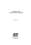
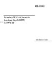
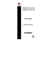
1
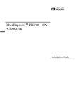
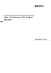
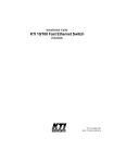
Installation Guide
10/100 Dual-speed
Fast Ethernet PCI Adapters
KF223TX, KF230TX
DOC.971115-KF223/230TX-K
P/N:750-0099-001
Ó 1997, KTI Networks Inc. All rights reserved. No part of this documentation may be reproduced in any form or by any means or used to
make any directive work (such as translation or transformation) without
permission from KTI Networks Inc.
KTI Networks Inc. reserves the right to revise this documentation
and to make changes in content from time to time without obligation
on the part of KTI Networks Inc. to provide notification of such revision or change.
For more information, contact:
United States
KTI Networks Inc.
P.O. BOX 631008
Houston, Texas 77263-1008
Phone: 713-2663891
Fax:
713-2663893
BBS:
713-2663015
E-mail:[email protected]
Web:
http://www.ktinet.com/
International
Fax:
886-2-6983873
BBS:
886-2-6983913
E-mail:[email protected]
Web:
http://www.ktinet.com.tw/
TRADEMARKS
Ethernet is a registered trademark of Xerox Corp. NetWare is a registered trademark
of Novell Inc.
WARNING:
This equipment has been tested and found to comply with the limits for a Class A
digital device, pursuant to Part 15 of the FCC Rules. These limits are designed to
provide reasonable protection against harmful interference when the equipment is
operated in a commercial environment. This equipment generates, uses, and can
radiate radio frequency energy and if not installed and used in accordance with the
instruction manual may cause harmful interference in which case the user will be
required to correct the interference at his own expense.
NOTICE:
(1)The changes or modifications not expressively approved by the party
responsible for compliance could void the user's authority to operate the
equipment.
(2)Shielded interface cables and AC power cord, if any, must be used in order to
comply with the emission limits.
CISPR A COMPLIANCE:
This device complies with EMC directive of the European Community and meets or
exceeds the following technical standard.
EN 55022 - Limits and Methods of Measurement of Radio Interference Characteristics of Information Technology Equipment. This device complies with CISPR Class
A.
WARNING: This is a Class A product. In a domestic environment this product may
cause radio interference in which case the user may be required to take adequate
measures.
CE NOTICE
Marking by the symbol CE indicates compliance of this equipment to the EMC
directive of the European Community. Such marking is indicative that this equipment meets or exceeds the following technical standards:
EN 55022: Limits and Methods of Measurement of Radio Interference characteristics of Information Technology Equipment.
EN 50082/1:Generic Immunity Standard -Part 1: Domestic Commercial and Light Industry.
EN 60555-2: Disturbances in supply systems caused by household appliances and similar
electrical equipment - Part 2: Harmonics.
10/100BASE-TX
FAST ETHERNET PCI ADAPTERS
INSTALLATION GUIDE
DOC.971114
DF223TX-KF230TX-NK
P/N:750-0099-002
Table of Contents
1. Introduction
1.1 Adapter Features ................................................................ 1
1.2 Connector and LEDs ........................................................... 2
2. Installing the Adapter
2.1 Installing the Adapter .......................................................... 3
2.2 Connecting to the Network .................................................. 4
3. Network Driver Installation
3.1 Driver Information ................................................................. 7
3.2 PCI BIOS Setup .................................................................. 8
4. Setup Program and Diagnostics
4.1 Running Setup Program ...................................................... 9
4.2 Functions on the Main Menu ............................................. 12
5. LED Indicators
5.1 Interpretations ................................................................... 17
Appendix
A.1 Specifications ................................................................... 18
A.2 RJ-45 Connectors & Cable ............................................... 19
A.3 Auto-negotiation Function ................................................. 20
A.4 Diagnostics Report ........................................................... 21
A.5 Installing Remote Boot ROM ............................................ 22
Figures
Figure 1-1 Network Connector and LEDs .................................. 2
Figure 2-1 Inserting the Adapter into the PCI Slot ..................... 4
Figure 2-2 Network Connector ................................................... 4
Figure 2-3 Connecting 10BASE-T Cable ................................... 5
Figure 2-4 Connecting 100BASE-TX Cable ............................... 6
Figure 4-1 Main Menu of the Setup Program ............................. 9
Figure 4-2 Adapter Information ................................................. 11
Figure 4-3 DOS ODI Driver Installation Window ....................... 12
Figure 4-4 Setup Menu ............................................................ 13
Figure 4-5 Diagnostics Menu .................................................. 14
Figure A-1 RJ-45 Connector Pin Assignments ........................ 19
1. Introduction
The 10/100BASE-TX Fast Ethernet PCI Adapter is a 32-bit LAN
adapter for use in personal computers with PCI computer bus slots.
This adapter is a dual-speed adapter and features one RJ-45 connector for either a 10 Mbps or a 100 Mbps IEEE 802.3 Ethernet network
connection over unshielded twisted-pair (UTP) cable. The adapter
automatically senses the connection speed, switches to either 10 Mbps
or 100 Mbps and indicates the link status on the LEDs.
1.1 Adapter Features
The features of the 10/100 Fast Ethernet PCI adapter are:
• High performance bus master operation with low processor
utilization
• Automatically senses 10 Mbps or 100 Mbps connection
• Supports auto-negotiation for the connection speed and duplex mode
• PCI revision 2.0 or later compliance, 32-bit PCI half-card
• Three status LEDs
• Optional RPL Boot ROM for network operating systems
• Supports 100BASE-TX connection with UTP Category 5 cabling
• Supports 10BASE-T connection with UTP Category 3, 4, or 5
cabling
• Setup software for quick driver installation and diagnostics
1
1.2 Connector and LEDs
Figure 1-1 shows the connector and LEDs on the adapter. The following table describes these components.
No. Components
Description
1
10/100 Mbps
This RJ-45 connector requires UTP
network connector cable for 10Mbps or 100 Mbps
connection.
2
100Mb Link LED
This LED lights when 100 Mbps
connection is selected and active.
3
10Mb Link LED
This LED lights when 10 Mbps
connection is selected and active.
4
Activity status LED This LED indicates a receive or a
transmission is in process.
Figure 1-1 Network Connector and LEDs
2
2. Installing the Adapter
This chapter describes how to install the Fast Ethernet PCI adapter
in a PCI computer and how to connect the adapter to the network.
Before installing the adapter, you need the following:
• A computer system that is compliant with the PCI specifications
version 2.0 or later.
• An available PCI bus master slot in the computer
• The adapter driver diskette
• UTP cables - use a UTP Category 5 cable with an RJ-45 plug
to operate at 100 Mbps - use a UTP Category 3, 4, or 5 cable
with an RJ-45 plug to operate at 10 Mbps
2.1 Installing the Adapter
To install the adapter in your computer, follow these steps:
1. Turn off the power to the computer and disconnect all cables
connected to the computer.
2. Remove the computer's cover.
3. Unscrew and remove the slot cover from the PCI bus master
slot that you plan to use.
4. Install optional Boot ROM, if you want to use the remote boot
ROM function. Refer to Appendix 5 for more information.
5. Insert the adapter into the slot and secure the screw (see Figure 2-1).
6. Replace the computer cover and reconnect all previously
connected cables.
3
Figure 2-1 Inserting the Adapter into the PCI Slot
2.2 Connecting to the Network
This section describes how to connect 10 Mbps or 100 Mbps network cables to the adapter. The rear bracket of the Fast Ethernet
adapter contains one RJ-45 connector. The connector is used for
either 100Mbps 100BASE-TX connection or 10Mbps 10BASE-T connection. The adapter can sense the connection speed and switch to
appropriate operation automatically.
Figure 2-2 Network Connector
4
10 Mbps Connection
For 10BASE-T Ethernet networks, the Fast Ethernet adapter uses
Category 3, 4, or 5 UTP cable. To establish a valid 10 Mbps connection, the cable must be connected to a 10BASE-T hub. Connect the
network cable as follows:
1. Make sure that the plug on the cable is wired appropriately for a
standard 10BASE-T adapter.
2. Align the RJ-45 plug on the end of the UTP cable with the notch
on the adapter's connector and insert it into the adapter connector as shown in Figure 2-3.
Figure 2-3 Connecting 10BASE-T Cable
5
100 Mbps Connection
For 100BASE-TX Fast Ethernet networks, the adapter supports Category 5 UTP cabling. To establish a valid 100 Mbps connection, the
cable must be connected to a 100BASE-TX hub.
1. Make sure that the plug on the cable is wired appropriately for a
standard 100BASE-TX adapter.
2. Align the RJ-45 plug on the end of the UTP cable with the notch
on the adapter's connector and insert it into the adapter connector as shown in Figure 2-4.
Figure 2-4 Connecting 100BASE-TX Cable
Note: The UTP wire pairs and configuration for 100BASE-TX cable
are identical to those for 10BASE-T cable when used with Category
5 UTP cable. The straight through connection should be made from
the adapter through the cable and connectors to the hub. Refer to
Appendix A.1 for RJ-45 connector pin assignments.
6
3. Network Driver Installation
After making the connection to the network, you must install the
adapter network driver in order to connect the Fast Ethernet adapter
to your network operating system.
3.1 Driver Information
The adapter driver diskette contains the latest versions of the network drivers available when the adapter is shipped from the factory.
A file, \README.DOC, located in the diskette's root directory contains a list of the supported driver software and the directory structures for the supported operating environments. Please refer to this
file first before installing any network driver for the adapter.
In the diskette, there are additional INSTALL.DOC files within the
directory structures for each supported operating environment. These
files contain information that pertains to the specified driver or operating environment that corresponds to the subdirectory where they
are found. The basic drivers supplied in the adapter driver diskette
are:
•
•
•
•
•
•
•
NetWare DOS ODI driver
NetWare OS/2 ODI driver
NetWare ODI server driver for NetWare 3.1x, 4.x, and Client32
DOS NDIS2 driver
OS/2 NDIS2 driver
NDIS3 driver for Windows NT
NDIS3 driver for Windows 95
In addition to the basic drivers, more updated information and drivers
7
may be included in the driver diskette after this guide is published.
Please refer to the \README.DOC file first for the latest information before you install any drivers.
3.2 PCI BIOS Setup
Before installing the driver, it is recommended to run the system PCI
BIOS setup utility to check each PCI slot that contains a Fast Ethernet
PCI adapter for the following PCI settings:
1. Enable/disable the PCI slot : make sure the PCI slot is enabled
for the adapter.
2. Assign an IRQ number : make sure the IRQ number does not
conflict with other add-in adapters.
3. Enable bus mastering : the PCI slot must be enabled for bus
mastering.
On a PCI plug-and-play system, the PCI BIOS automatically configures the adapter, so there is no user action needed.
Note:
* When the PCI adapter is installed in some PCI computers with
EISA slots, you must run the EISA configuration utility. If the
utility is not available, consult your computer supplier.
8
4. Setup Program
4.1 Running Setup Program
One setup program, SETUP.EXE, is contained in the adapter driver
diskette. The Setup program is a DOS program for you to perform the
following functions from its main menu as illustrated in Figure 4-1:
Install menu: supports a quick method to install NetWare DOS ODI
client driver on your computer. It also provides the instructions for
installing drivers for various operating systems.
Setup menu: enable full-duplex mode for Connectivity test.
Diagnostics menu: performs diagnostic tests for the adapter. A Connectivity test is also provided in this menu for testing the network
connection between two computers that each one is installed one
PCI adapter.
Figure 4-1 Main Menu of the Setup Program
9
You can run the program and perform the tests at any time after
installing the adapter to verify the installation or you can run it when a
fault is suspected.
Before running the program
Before running the setup program, make sure that the adapter is correctly installed in a computer with the PCI bus.
The setup program must be run from the DOS prompt. When using
the program to run diagnostics on the adapter, you should not load
memory managers or other device drivers. To avoid this, press [F5]
when DOS (version 6.x) loads, after the message "Starting MSDOS..." appears on the screen. This prevents the AUTOEXEC.BAT
and CONFIG.SYS files from being executed.
When the program is executed, it detects all installed Fast Ethernet
PCI adapters in the computer and shows the basic information of the
first adapter found. You may press [PgUp] key or [PgDn] key to
browse the information of each adapter and select a target adapter to
perform the optional tests shown on the main menu.
Together with the SETUP.EXE, a SETUP.DOC file is also contained
in the adapter driver diskette. It contains detailed information about
this program.
10
Starting the Setup Program
To start the Setup program, follow these steps:
1. Insert the adapter driver diskette labeled "1 of 2" into floppy disk
drive A:.
2. Execute the following command from DOS prompt:
A>SETUP <enter>
A screen appears showing a menu bar on top of the screen and an
information window for the first adapter found in the computer on the
bottom portion of the screen as illustrated in the following figure:
Figure 4-2 Adapter Information
When Multiple Adapters are installed
If multiple adapters are found, you may press [PgDn] or [PgUp] to
browse the information of each adapter and select a adapter for the
optional menus (Setup and Diagnostics).
11
4.2 Functions on the Main Menu
This section describes the functions of "Install", "Setup", and "Diagnostics" menu on the main menu as follows:
Running "Install" Menu
The "Install" menu provides two functions as follows:
• Install NetWare DOS ODI driver
This function provides a convenient and quick method to install the
Novell's NetWare DOS ODI driver for your computer without the
need for Novell's installation diskettes. The pop-up window for the
installation is illustrated in figure 4-3. Specify the parameters in the
window for your environment and click [OK] to complete the installation.
Figure 4-3 DOS ODI Driver Installation Window
• Installation instructions for Other Network Operating Systems
This function provides the helpful instructions for installing other drivers for various operating systems.
12
Running "Setup" Menu
This menu allows you to configure full-duplex mode for
the adapter before running Connectivity test.
Figure 4-4 Setup Menu
"Auto Detection" selection allows adapter to configure duplex mode automatically. "Full Duplex Enabled" selection
will force the adapter to use full duplex mode.
This setting will not be effective after any network driver is
loaded or the computer is reboot.
13
Running "Diagnostics" Menu
This menu provides two useful functions: Diagnostics and Connectivity test.
Figure 4-5 Diagnostics Menu
Diagnostics test function allows you to test the major components
and verify the basic operations of the selected adapter. It performs
many tests for the selected adapter and indicates the result of each
test on a report window. Refer to Appendix 4 for more information.
Connectivity Test allows you to test the adapter's ability to transmit
and receive data while on the network. To run the test, you need a
second computer set up as an echo station. The echo station receives
packets from the adapter being tested and echoes (loopback) them
back to the adapter over the network.
14
To set up an echo station, follow these steps:
1. Install another adapter which is known to have no problem into a
second computer as instructed in Chapter 2.
2. Run SETUP.EXE on that computer.
3. Press [F10] and press [® ] to select "Diagnostics" from the main
menu.
4. Select "Connectivity Test" and press [Enter].
5. Select "Start Echo Station Test" from "Connectivity Test" pop-up
window and press [OK]. The computer becomes an echo
station. It will receive every packet with address 00 11 11 11 11
11 and echo the packets back to the adapter from which the
packets were sent.
You may start the Connectivity Test for the adapter after an echo
station has been set up. Follow these steps:
1. Press [PgDn] or [PgUp] to select the adapter you want to test.
2. Press [F10] and press [® ] to select "Diagnostics" from the main
menu.
3. To configure the number of packets to be performed for the
"Network Link Test" in step 4, you may select "Test Configuration" item from the pop-up menu to enter the number:
15
4. Select "Connectivity Test" and press [Enter].
5. Make sure an echo station is ready. Select "Start Network Link
Test" from "Connectivity Test" pop-up window and press [OK]
to start the test.
A status window will report several packet counters as shown below:
The "Transmit" counters indicate the number of good and bad packets which have been sent to the echo station. The "Receive" counters
show the number of good and bad packets echoed back from the
echo station. This test is also very useful in verifying a path between
two computers on the network.
16
5. LED Indicators
Each Fast Ethernet adapter has three LEDs, as shown in Figure 1-1.
5.1 Interpretations
The interpretations of the LEDs are:
100Mb LED indicates an active 100Mbps connection is established.
On : Good connection between adapter and 100BASE-TX hub
Off : No connection between adapter and hub
Blink: Not applicable
10Mb LED indicates an active 10 Mbps connection is established.
On : Good connection between adapter and 10BASE-T hub
Off : No connection between adapter and hub
Blink : Not applicable
Activity LED indicates packets are being received or transmitted.
Blink : Network traffic is present
On : Not applicable
Off : No traffic for either speed
If you experience any problems, first make sure that the appropriate
driver is loaded, the proper cable is connected to the connector, and
the hub complies with the adapter specifications (10 Mbps 10BASET or 100 Mbps 100BASE-TX). Then recheck the LED.
17
Appendix
A1. Specifications
Network std.:
10 Mbps IEEE 802.3 10BASE-T Ethernet
100 Mbps IEEE 802.3u 100BASE-TX Fast Ethernet
Dimensions:
MX98713 NIC
KF223TX NIC
RTL8139 NIC
KF230TX NIC
80mm x 125mm (3.15" x 4.92")
80mm x 125mm (3.15" x 4.92")
50mm x 120mm (1.97" x 4.72")
50mm x 120mm (1.97" x 4.72")
RTL8139 NIC 50mm x 120mm (1.97" x 4.72")
KF230TX NIC 50mm x 120mm
Environmental: Operating temperature 0o to 40oC
Humidity 10% to 90% non-condensing
Power:
MX98713 NIC +5V 500mA max.
KF223TX NIC +5V 500mA max.
RTL8139 NIC +5V
KF230TX NIC +5V
18
A2. RJ-45 Connector & Cables
Figure A-1 shows the pin assignments of the RJ-45 connector for
10BASE-T and 100BASE-TX network. The pin assignments are identical for 10BASE-T and 100BASE-TX, using Category 5 UTP cable.
Pin
1
2
3
4
5
6
7
8
Signal Name
Transmit +
Transmit Receive +
NC (no connection)
NC (no connection)
Receive NC (no connection)
NC (no connection)
Figure A-1 RJ-45 Connector Pin Assignments
Cabling Requirements:
10Mbps
10BASE-T Ethernet Category 3, 4, or 5 UTP Cable
The maximum distance is 100 meters.
100 Mbps 100BASE-TX Ethernet Category 5 UTP Cable
The maximum distance is 100 meters.
19
A.3 Auto-negotiation Function
The adapter is equipped with an auto-negotiation function. Auto-negotiation is a negotiation procedure between two connected devices.
Both devices must be auto-negotiation capable. The procedure decides the best operation modes that can be used for the data transfer
operation between two connected devices. The operation modes includes connection speeds and duplex modes as follows:
Connection speed : 10Mbps or 100Mbps
Duplex mode : half-duplex or full-duplex
Operating at full duplex can increase the network bandwidth to up to
20 Mbps or depending on the connection speed 200 Mbps.
The following table describes how the adapter decides the operation
modes when it connects to :
An auto-negotiation device
Speed: via auto-negotiation
Duplex: via auto-negotiation
A non-auto-negotiation device
Speed: auto-sense the connection speed
Duplex: half-duplex as default (*)
* The default could be overwritten by configuration setting or
keyword setting of each individual network driver when the
driver is loaded.
20
A.4 Diagnostics Report
When running "Diagnostics" from the SETUP program, the program
indicates the result of each test on the Diagnostics Report window.
Depending on the adapter model, the report window is shown as follows:
MX98713 NIC
RTL8139 NIC
21
A.5 Installing Remote Boot ROM
Before you can use the remote boot function, you have to setup the
remote boot service on the file server and install the remote boot
ROM onto the adapter.
To install the boot ROM, make sure the notch of the boot ROM is in
the same direction as the notch of the socket on the adapter. The
remote boot ROM socket is labeled U5 on the MX98713 NIC or it is
labeled U2 on the RTL8139 NIC.
Refer to the \BOOTROM subdirectory in the driver diskette for more
detailed instructions on how to setup the remote boot service on a file
server.
22