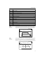
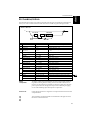
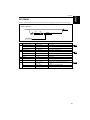
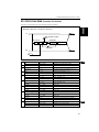
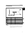
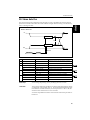
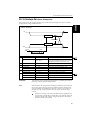
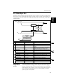
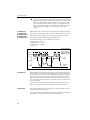
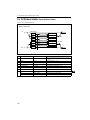
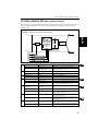
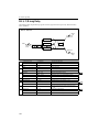
1
E
1
Table of Contents
Table of Contents
Overview ......................................................................................................... 1
Insert Effects.............................................................................................. 1
Effect Size ........................................................................................... 2
Effect Input/Output ......................................................................... 2
Grouping ............................................................................................ 3
Master Effects ........................................................................................... 3
Program ..................................................................................................... 4
Program - Single/Double OSC mode ............................................ 4
Program - Drums OSC mode .......................................................... 5
Combination ............................................................................................. 6
Sequencer .................................................................................................. 8
Dynamic Modulation................................................................................... 10
Insert Effect size1
00: Amp Simulation...................................................................................... 13
01: Compressor ............................................................................................. 14
02: Limiter...................................................................................................... 15
03: Gate........................................................................................................... 17
04: Overdrive/Hi-Gain................................................................................ 19
05: Parametric 4EQ (Parametric 4-Band EQ) ............................................ 20
06: Graphic 7Band EQ.................................................................................. 22
07: Wah/Auto Wah...................................................................................... 23
08: Random Filter ......................................................................................... 25
09: Dyna Exciter ............................................................................................ 26
10: Sub Oscillator .......................................................................................... 27
11: Decimator ................................................................................................ 28
12: Chorus...................................................................................................... 29
13: Harmonic Chorus ................................................................................... 30
14: Ensemble.................................................................................................. 31
15: Flanger ..................................................................................................... 32
16: Tempo Flanger ........................................................................................ 33
17: Envelope Flanger.................................................................................... 34
18: Phaser ....................................................................................................... 35
19: Tempo Phaser ......................................................................................... 36
20: Envelope Phaser ..................................................................................... 37
21: Vibrato...................................................................................................... 38
22: Resonator ................................................................................................. 39
23: Ring Modulator ...................................................................................... 40
24: Tremolo.................................................................................................... 42
25: Rotary Speaker........................................................................................ 43
26: Delay......................................................................................................... 44
27: Multitap Delay ........................................................................................ 45
28: Early Reflections ..................................................................................... 46
i
Table of Contents
Insert Effect size2
00: St. Amp Simulation (Stereo Amp Simulation)................................... 47
01: Stereo Compressor ................................................................................. 48
02: Stereo Limiter.......................................................................................... 49
03: Multiband Limiter.................................................................................. 50
04: Stereo Gate .............................................................................................. 51
05: OD/Hi-Gain Wah (Overdrive/Hi-Gain Wah) .................................. 53
06: St. Parametric 4EQ (Stereo Parametric 4-Band EQ) .......................... 55
07: St. Graphic 7EQ (Stereo Graphic 7-Band EQ) .................................... 56
08: Graphic 13Band EQ................................................................................ 57
09: St. Random Filter (Stereo Random Filter)........................................... 58
10: Stereo Enhancer ...................................................................................... 60
11: Talking Modulator ................................................................................. 61
12: Stereo Decimator .................................................................................... 63
13: Stereo Chorus.......................................................................................... 64
14: St. Harmonic Chorus (Stereo Harmonic Chorus).............................. 66
15: Multitap Chorus/Dly (Multitap Chorus/Delay) .............................. 67
16: Ensemble ................................................................................................. 68
17: Stereo Flanger ......................................................................................... 69
18: St. Random Flanger (Stereo Random Flanger) .................................. 70
19: St. Tempo Flanger (Stereo Tempo Flanger)........................................ 72
20: Stereo Phaser........................................................................................... 73
21: St. Random Phaser (Stereo Random Phaser) ..................................... 74
22: St. Tempo Phaser (Stereo Tempo Phaser)........................................... 75
23: St. Bi-phase Mod. (Stereo Bi-phase Modulation)............................... 76
24: Stereo Vibrato ......................................................................................... 78
25: 2-Voice Resonator .................................................................................. 80
26: Doppler.................................................................................................... 82
27: Stereo Tremolo........................................................................................ 84
28: Stereo Auto Pan...................................................................................... 85
29: St. Envelope Pan (Stereo Envelope Pan)............................................. 87
30: Stereo Dyna Pan ..................................................................................... 89
31: Phaser+Tremolo ..................................................................................... 91
32: Shimmer .................................................................................................. 93
33: Detune...................................................................................................... 95
34: Pitch Shifter............................................................................................. 96
35: Pitch Shift Mod. (Pitch Shift Modulation) .......................................... 98
36: Rotary Speaker...................................................................................... 100
37: Dual Delay............................................................................................. 102
38: Stereo Delay .......................................................................................... 103
39: St. Multitap Delay (Stereo Multitap Delay)...................................... 104
40: L/C/R Delay ........................................................................................ 105
41: Tempo Delay......................................................................................... 106
42: St. Modulation Delay........................................................................... 108
43: St. Dynamic Delay (Stereo Dynamic Delay)..................................... 110
44: Random Panning Dly (Random Panning Delay) ............................ 112
45: Early Reflections .................................................................................. 113
46: Reverb-Hall .......................................................................................... 114
47: Reverb-SmoothHall ............................................................................ 114
48: Reverb-Room ........................................................................................ 116
49: Reverb-BrightRoom ............................................................................ 116
50: Reverb-Wet Plate ................................................................................. 118
51: Reverb-Dry Plate ................................................................................. 118
ii
Table of Contents
Insert Effect size4
00: Piano Body/Damper (Piano Body/Damper Simulation) .............. 119
01: St. Mlt.band Limiter (Stereo Multiband Limiter)............................. 120
02: OD/Hyper-Gain Wah (Overdrive/Hyper-Gain Wah)................... 121
03: St. Graphic 13EQ (Stereo Graphic 13-Band EQ)............................... 122
04: Vocoder .................................................................................................. 123
05: St. Harmonic Chorus (Stereo Harmonic Chorus) ............................ 124
06: Multitap Chorus/Dly (Multitap Chorus/Delay) ............................ 126
07: Stereo Ensemble.................................................................................... 128
08: St. Tempo Flanger (Stereo Tempo Flanger) ...................................... 129
09: St. Tempo Phaser (Stereo Tempo Phaser) ......................................... 130
10: St. Pitch Shifter (Stereo Pitch Shifter) ................................................ 131
11: 2Band Pitch Shifter ............................................................................... 132
12: Rotary Speaker OD (Rotary Speaker Overdrive)............................. 133
13: Early Reflections ................................................................................... 135
14: L/C/R Long Delay............................................................................... 136
15: Stereo Long Delay ................................................................................ 137
16: Dual Long Delay................................................................................... 138
17: St. Tempo Delay (Stereo Tempo Delay) ............................................ 139
18: Hold Delay ............................................................................................ 140
Master Effects
Modulation
00: Flanger ................................................................................................... 142
01: Phaser ..................................................................................................... 143
02: Multitap Chorus/Dly (Multitap Chorus/Delay) ............................ 144
03: Ensemble................................................................................................ 145
04: Chorus.................................................................................................... 146
05: L/C/R Delay......................................................................................... 147
Reverb/Delay
00: L/C/R Long Delay............................................................................... 148
01: Delay/Reverb........................................................................................ 149
02: Reverb-Room ........................................................................................ 151
03: Reverb-Bright Room ............................................................................ 151
04: Reverb-Hall ........................................................................................... 153
05: Reverb-Smooth Hall............................................................................. 153
06: Reverb-Wet Plate .................................................................................. 153
07: Reverb-Dry Plate .................................................................................. 153
Index............................................................................................................. 154
iii
Overview
Overview
The TRINITY series has two types of effects: Insert Effects and Master Effects.
As shown in the figure below, you can use the Insert Effects in the process of sound creation after the
Oscillator, Filter, and Amp. Then, reverberation and other effects are applied through the Master Effects.
One hundred Insert Effects and fourteen Master Effects enable highly flexible sound production.
Send
Oscillator
Filter
Amp
Insert Effect
Master Effect
Return
+
EQ
The TRINITY series does not have an input level meter to recognize the effect input level. Please
note that if the input level is not high enough, the S/N ratio may be reduced, and if the input level
is excessive, clipping may occur.
To obtain the optimum degree of effects, first set the input level of the Insert Effect and Master
Effect to the maximum possible without clipping, then adjust the effect output level using the Wet/
Dry parameter of the Insert Effects, and the Output Level parameter and/or Return 1 and 2 of the
Master Effects.
The following table shows the parameters that can be used to adjust the input/output levels:
Program Edit mode
Input
Output
Combination Edit mode
Sequencer mode
OSC1/2 High, Low Level (P1)
Filter1/2 A/B Gain (P3)
Amp1/2 Level (P5)
Send1/2 (P5 or P7)
Trim Parameter (P7, P8)*
Volume (P1)
Send1/2 (P1)
Trim Parameter (P7, P8)*
Volume (P1)
Send1/2 (P1)
Wet/Dry (P7)
Output Level (P8)
Retrurn1, 2 (P8)
Wet/Dry (P7)
OutPut Level (P8)
Return1, 2 (P8)
Output Level (P8)
Return1, 2 (P8)
* Certain effects may not utilize some of these parameters.
Insert Effects
Insert Effects are used as part of the sound creation process.
You can select any effects from the effect library, which contains 100 effects, ranging from effects that
change tone and dynamics, such as the equalizer, limiter, exciter, etc.; to effects that simulate particular
characteristics of certain musical instruments, such as amp simulation, rotary speaker, and piano body/
damper simulation; effects that create conventional effect sounds, such as ring modulator, talking modulator, vocoder, and pitch shifter; completely new types of effects, such as decimator and resonator; and
classic effects, such as reverberation, chorus, delay, and overdrive.
Insert Effects employ the concept of “size”, which allows for more flexible effect routing appropriate for
your own application.
In Program mode, you can use up to three effects in series (or up to four effects in series/parallel for a
Drum mode Program).
In the Combination and Sequencer modes, you can use up to three effects in series for each Timbre or
Track (or up to four effects in series/parallel for each Timbre or Track that uses a Drum mode Program).
In total, you can use up to eight effects for all Timbres/Tracks.
For more detailed information, refer to the block diagrams and explanations below for each mode.
1
Overview
Effect Size
Insert Effects utilize effect sizes of 1, 2, and 4.
Program (Single or Double mode Program):
Up to three effects with a total effect size of four or less can be inserted in series.
Size
Size
Size
1
1
2
Program (Drum mode Program):
Up to four effects with a total effect size of four or less can be inserted in series/parallel.
Use P5 (DrumKit) in Global mode to assign the DrumKit sounds to Insts 1–4 for each key.
Inst1
Size
Inst2
Size
Inst3
Size
Inst4
Size
Size
Inst1
1
2
Inst1
Size
4
Size
Inst2
1
2
1
Inst1
Size
Size
1
1
Inst3
Size
Inst4
Size
1
1
1
Combination:
Up to eight effects with a total effect size of eight or less can be inserted.
Size
Timbre1
Timbre2
Timbre1
4
Size
Size
Size
1
1
2
Size
Size
Size
4
2
2
Size
Size
Size
4
2
2
Sequencer:
Up to eight effects with a total effect size of eight or less can be inserted.
Size
Track1
Track2
Track1
4
Size
Size
Size
1
1
2
Effect Input/Output
The following table shows the input/output of the Dry sound (the sound without any effect applied) and
the Wet sound (the sound with an effect applied) for each size.
size1
size2
size4
Dry
Wet
Dry
Wet
Dry
Wet
Dry
Wet
Mono In - Mono Out
Mono In - Mono Out
Stereo In - Stereo Out
Mono In - Mono Out
Stereo In - Stereo Out
Mono In - Stereo Out
Stereo In - Stereo Out
Stereo In - Stereo Out
Effect
+
Effect
+
Effect
Effect
Effect
Shown on the upper left corner of the effect block diagrams.
The Size 1 effects are all monaural in/monaural out for both dry and wet sounds. Therefore, Size 1 effects
have monaural input as shown in the figure on the next page. If the Effect On/Off parameter is turned
Off, the effect is bypassed. When a size 1 effect is selected, the bypass sound becomes monaural.
Regardless of the Effect On/Off setting, you can turn all Insert Effects Off by sending the Effect 2
Control message (Controller #92). When the Controller value is 0, all effects turn Off. They turn On
with a value of 1–127.
2
Overview
When you want to preserve the stereo image of a Double mode Program, use Insert Effects of size 2 or 4.
Stereo In
Size
4
Stereo In
Size
Size
2
2
Mono In
Size
Size
Size
1
1
2
Grouping
You can use the grouping function in the Combination and Sequencer modes to use the Insert Effects efficiently. The effect grouping function places the Timbres/Tracks into one group so that the same Insert
Effects will be applied to all of them.
Note the following when you are trying to place Timbres/Tracks that use Single or Double mode Programs, and Timbres/Tracks that use Drum mode Programs into a group:
• When you are adding Timbres/Tracks that use Single or Double mode Programs to a group of Timbres/Tracks that use Drum mode Programs:
The Timbres/Tracks will be grouped (input) to Insert Effect inst1 of the Timbres/Tracks that use Drum
mode Programs.
• When you are adding Timbres/Tracks that use Drum mode Programs to a group of Timbres/Tracks
that use Single or Double mode Programs:
Only DrumKit sounds that have been assigned to inst1 in P5 of Global mode will be grouped (input) to
the Insert Effects of the Timbres/Tracks that use Single or Double mode Programs.
Master Effects
Master Effects use a send and return routing regardless of the modes, and consist of two types of effects:
modulation and reverberation/delay, both mono-in/stereo-out. These fourteen effects can be used to provide overall ambience. It is possible to route the modulation effects and reverb/delay effects in series.
Send levels are set for each oscillator, or after the Insert Effects are applied. In the Combination and
Sequencer modes, you can set the send levels for each Timbre/Track, allowing you to use the unit as a
mixer to create a spacious effect for entire Programs, Combinations, or Songs.
A Low/High-type shelving EQ is located before the output connectors 1/L/MONO and 2/R, and allows
you to “fine-tune” the tone of your sound.
The Master Effect parameters are set for each Program, Combination, and Song. (Use P8 in each mode.)
The Effect 4 Control message (Controller #94) will turn the modulation effects on/off, and the
Effect 5 control message (Controller #95) will turn the reverb/delay effects on/off. Both control
messages are sent on the Global MIDI Channel. With a control value of 0, the effect is turned off,
and with a value of 1–127, the effect is turned on.
The Effect 3 Level message (Controller #93) will adjust the send level of the modulation effects, and
the Effect 1 Level message (Controller #91) will adjust the send level of the reverb/delay effects.
The control messages for Programs are sent on the Global MIDI Channel, and control messages for
Combinations and Sequences are sent on the MIDI Channels specified for each Timbre and Track.
3
Overview
Program
You can use the Insert Effects as long as the total of the effect size is four or less in Program mode.
The configuration of the Insert Effects is different when using a Single or Double mode Program than
when using a Drum mode Program.
Program - Single/Double OSC mode
Amp1/2 Mod
(Program Edit P5)
Master Effects
(Program Edit P8)
Insert Effects
(Program Edit P7)
in the case of
Insert Effect =Off *
Master Effects
+
Send1
Filter1
Pan1
Modulation
+
+
Send2
OSC1
+
OUT3
Reverb/Delay
Send1
Amp1
Pan
Send2
Return2
Send1
Send2
OSC2
Filter2
OUT4
Pan2
+
Amp2
Pan
+
+
+
Insert Effects
E1
E2
Return1
+ +
LEQ
+
+
E3
+
+
HEQ
+
OUT1
+
OUT2
Pan Width
in the case of
Insert Effect =On
Low Gain High Gain
Insert Effect =Off *
Program - Single / Double OSC Mode
* Insert Effect =Off: size =0
Insert Effects
You can insert up to three effects in series as long as the total of the effect sizes is four or less when you
are using a Program with the Oscillator Mode parameter (1–1c) set to single or double (shown as E1, E2,
and E3 in the center of the figure above).
If you insert a size 1 effect, the input/output becomes monaural. In this case, the oscillator’s Pan parameter (P5 in Program Edit mode) becomes ineffective, and the pan setting will be in the center. Adjust the
stereo pan position using the Pan parameter that comes after the Insert Effects (P7 in Program Edit mode).
If the Insert Effect output is in stereo, you can control the width of the effect (such as the width of reverberation) using the Width parameter (P7 in Program Edit mode). If you wish to make the oscillator’s Pan
setting (P5 in Program Edit mode) effective, set the Pan setting that comes after the Insert Effects to C064
and set the Width to 127.
Insert Effect - Pan, Width
Pan=L000
Pan=L000
Pan=R127
Pan=C064, Width=127
Pan=C064, Width=64
Pan=C064, Width=32
Pan=C064, Width=0
Left
Center
Right
Pan=L000
Pan=R127
Pan=R127
Pan=C064, Width=127
Pan=L048, Width=127
Pan=L032, Width=127
Pan=L016, Width=127
Left
Center
Right
Pan=R096, Width=127
Pan=R096, Width=64
Pan=L048, Width=127
Pan=L048, Width=64
Left
Center
Right
Master Effects
The input level of the Master Effects is set by Send 1 and 2.
Since the destination of the send routing changes depending on whether the Insert Effects have been
inserted or not, the parameters will change accordingly.
If you have inserted Insert Effects, the Send 1 and 2 parameters of P7 in Program Edit mode will become
effective (those of P5 will be ignored). If you have not inserted Insert Effects, the Send 1 and 2 parameters
of P5 in Program Edit mode will become effective.
The Send 1 and 2 parameters are also used to set the level of the signal appearing at output connectors 3
and 4.
Only the Master Effect sound will be sent to output connectors 3 and 4. If you wish to output dry sound
(without the Master Effects applied), set the Master Effect parameters of P8 in Program Edit mode to
“Off.” In this case, however, the Master Effects will not be applied to the signal at outputs 1 and 2.
4
Overview
If output connectors 3 and 4 are used for stereo output, you can set the stereo position of Send 1 and 2
using the Pan 3 and 4 parameters (P8 in Program Edit mode).
To set the Master Effect return level, use the Return 1 and 2 parameters (P8 in Program Edit mode).
If you check the check box located between Send 1 and Send 2 in the upper left corner of the LCD, the
serial routing of Modulation → Reverb/Delay will be added. That is, the Right modulation output will be
added to the Reverb/Delay input. In this case, you can still set the Return 1 and 2 parameters independently.
Program - Drums OSC mode
DrumKit
(Global P5)
Master Effects
(Program Edit P8)
Insert Effects
(Program Edit P7)
Amp1/2 Mod
(Program Edit P5)
Insert Effect=Off
Master Effects
Send1
+
Send1
+
Send2
+
Send2
Pan1
Modulation
+
OUT3
Reverb/Delay
OUT4
Pan2
Kick
Pan
Send1
Insert
Effects
+
Send1
+
Send2
+
Snare
Pan
+
+ + Send2
+
+ + Send2
+
+
Send2
+
Pan
+
+
Send1
+
Send2
Inst1/2/3/4 ->E1/E2/E3/E4
Insert Effect=inst2
Tom
Pan
+
+
Send1
+ +
HEQ
+
OUT1
+
OUT2
Low Gain High Gain
+
+
+
Send2
+
Pan Width
E2
+
Pan Width
+
E3
+
Send1
Pan Width
+ +
+
H.Hat
LEQ
+
+
+
Insert Effect=inst1
Return1
+
E1
Send1
Send1
Return2
+
Send2
+
E4
+
Insert Effect=inst3
Pan Width
Send1
Send2
+
Conga
Pan
+
Insert Effect=inst4
Insert Effect=Off
Program - Drums OSC Mode
Insert Effects
You can insert up to four effects in series or parallel as long as the total of the effect sizes is four or less
when you are using a Drum mode Program (shown as E1, E2, E3, and E4 in the center of the figure
above).
You can select Insert On/Off, and inst 1–4 (using E1–E4 input), and set the Pan and Send 1/2 parameters
for each Drum sound in P5 of Global mode for each key. The final send setting will use the value set here
multiplied by the Send setting set in P5 of Program Edit mode.
If you insert a size 1 effect, the input/output becomes monaural. In this case, the DrumKit’s Pan parameter (P5 in Global mode) becomes ineffective, and the sound will be panned in the center. Adjust the stereo
position using the Pan parameter (P5 of Program Edit mode) that comes after the Insert Effects (P7 in Program Edit mode).
If the Insert Effect output is in stereo, you can control the width of the effect (such as the width of reverberation) using the Width parameter (P7 in Program Edit mode). If you wish to make the DrumKit’s Pan
setting (P5 in Global mode) effective, set the Pan setting that comes after the Insert Effects to C064 and set
the Width to 127.
Master Effects
The input level of the Master Effects is set by Send 1 and 2.
Since the destination of the send routing changes depending on whether the Insert Effects have been
inserted or not, the parameters will change accordingly.
5
Overview
If you have inserted Insert Effects, the Send 1 and 2 parameters of P7 in Program Edit mode will become
effective (those of P5 will be ignored). If you have not inserted Insert Effects, the Send 1 and 2 parameters
of P5 in Global mode and P5 in Program Edit mode will become effective.
The Send 1 and 2 parameters are also used to set the level of signal appearing at output connectors 3 and
4.
Only the Master Effect sound will be sent to output connectors 3 and 4. If you wish to output dry sound
(without the Master Effects applied), set the Master Effect parameters of P8 in Program Edit mode to
“Off.” In this case, however, the Master Effect will not be applied to the signal at outputs 1 and 2.
If output connectors 3 and 4 are used for stereo output, you can set the stereo position of Send 1 and 2
using the Pan 3 and 4 parameters (P8 in Program Edit mode).
To set the Master Effect return level, use the Return 1 and 2 parameters (P8 in Program Edit mode).
If you check the check box located between Send 1 and Send 2 in the upper left corner of the LCD, the
serial routing of Modulation → Reverb/Delay will be added. That is, the Right modulation output will be
added to the Reverb/Delay input. In this case, you can also set the Return 1 and 2 parameters independently.
Combination
Mixer
(Combination Edit P1)
Timbre1
Insert Effect Grouping
(Combination Edit P7)
in the case of
Insert Effect =Off
Master Effects
+
Send1
Filter1
+
Insert Effect=Off
+
Send2
OSC1
Send2
Pan
+
E1
+
in the case of
Insert Effect =On
in the case of
Insert Effect =Off
+
Send1
+
Send2
OSC1
Filter1
E2
Pan
+
Return1
LEQ
+
+
+
HEQ
+
OUT1
+
OUT2
Send1
Send2
+
Amp2
Return2
+
Low Gain High Gain
+
Send2
Filter2
+
Pan Width
Send1
OSC2
OUT4
+
E3
+
Amp1
Pan
OUT3
Reverb/Delay
+ +
Assigning / Grouping
Timbre to Insert Effects
+
Amp2
Insert Effects
+
Send2
Timbre2
+
Send1
Amp1
Send1
Filter2
Pan1
Modulation
Pan2
Pan
OSC2
Master Effects
(Combination Edit P8)
+
+
Insert Effects
+ +
+
E1
E2
E3
+
Pan Width
in the case of
Insert Effect =On
up to
Timbre8
Insert Effect=Off
Combination
Insert Effects
The Insert Effects selected in Program Edit mode are not used in Combination Edit mode. Instead, you
can set Insert Effects for up to eight Timbres in a Combination.
Go to P7 in Combination Edit mode, and set the Insert Effect’s Off, size (1, 2, 4, 8), and grouping parameters for each of Timbres 1–8.
If you wish to use a Program’s Insert Effect settings by using the Copy function, first select a size for the
corresponding Timbre equal to or greater than the size of the effects used in the Program.
You can route up to three Insert Effects for each Timbre in series. (If the Program is using a DrumKit, you
can use up to four effects in series or parallel.)
The total effect size for all the Timbres must be eight or less.
6
Overview
You can also set the total effect size for a single Timbre to eight. However, if you are routing three Insert
Effects in series, you cannot place an effect of size 4 on the second position. For a Timbre that uses a Drum
mode Program, you can set the total effect size to eight. However, if you are routing three Insert Effects in
series, you cannot place the effect of size 4 on the second position. If you are routing four effects in series,
you cannot place an effect of size 4 on the second or third position.
If you insert a size 1 effect, the input/output becomes monaural. In this case, the Timbre’s Pan parameter
(P1 Timb Param1 in Combination Edit mode) becomes ineffective, and the pan setting will be in the center. Adjust the stereo pan position using the Pan parameter (P7 in Combination Edit mode) that comes
after the Insert Effects.
If the Insert Effect output is in stereo, you can control the width of the effect (such as the width of reverberation) using the Width parameter (P7 in Combination Edit mode). If you wish to make the oscillator’s
Pan setting (P5 in Program Edit mode) effective, set the Pan setting that comes after the Insert Effects to
C064 and set the Width to 127.
Refer to the “Program - Drums OSC mode” section for information regarding the setting of Programs that
use a DrumKit.
When you are adding Timbres/Tracks that use Single or Double mode Programs to a group of Timbres/Tracks that use Drum mode Programs, they will be grouped (input) into Insert Effect inst1 of
the Timbres/Tracks that use Drum mode Programs.
When you are adding Timbres/Tracks that use Drum mode Programs to a group of Timbres/
Tracks that use Single or Double mode Programs, only DrumKit sounds that have been assigned to
inst1 in P5 of Global mode will be grouped (input) into the Insert Effects of the Timbres/Tracks
that use Single or Double mode Programs.
Master Effects
You need to set the Master Effects in the Combination, since the Master Effects set in Program Edit mode
are ineffective here.
The input levels of the Master Effects are set by Send 1 and 2.
Since the destination of the send routing changes depending on whether Insert Effects have been inserted
or not, the parameters will change accordingly.
If you have inserted Insert Effects, the Send 1 and 2 parameters of P7 in Combination Edit mode will
become effective (those of P1 Timb Param1 will be ignored). If you have not inserted Insert Effects, the
Send 1 and 2 parameters of P1 Timb Param1 in Combination Edit mode will become effective.
The Send 1 and 2 parameters are also used to set the level of signal appearing at output connectors 3 and
4.
Only the Master Effect sound will be sent to output connectors 3 and 4. If you wish to output dry sound
(without the Master Effects applied), set the Master Effect parameters of P8 in Combination Edit mode to
“Off.” In this case, however, the Master Effects will not be applied either to the output 1 or 2 signal.
If output connectors 3 and 4 are used for stereo output, you can set the stereo position of Send 1 and 2
using the Pan 3 and 4 parameters (P8 in Combination Edit mode).
To set the Master Effect return level, use the Return 1 and 2 parameters (P8 in Combination Edit mode).
If you check the check box located between Send 1 and 2 in the upper left corner on the LCD, the serial
routing of Modulation → Reverb/Delay will be added. That is, the Right modulation output will be
added to the Reverb/Delay input. In this case, you can still set the Return 1 and 2 parameters independently.
7
Overview
Sequencer
Track Play / Rec
(Sequencer P1)
Track1
Insert Effect Grouping
(Sequencer P7)
in the case of
Insert Effect =Off
Master Effects
+
Send1
Filter1
+
Insert Effect=Off
+
Send2
OSC1
Send1
Amp1
Send2
Send1
Pan
+
E1
+
in the case of
Insert Effect =On
in the case of
Insert Effect =Off
Track2
+
Send1
+
Send2
OSC1
Filter1
E2
Pan
+
Return1
LEQ
+
+
+
+
HEQ
+
OUT1
+
OUT2
Send1
Send2
+
Amp2
Return2
Low Gain High Gain
+
+
Send2
Filter2
+
Pan Width
Send1
OSC2
OUT4
+
E3
+
Amp1
Pan
OUT3
Reverb/Delay
+ +
Assigning/Grouping
Track to Insert Effects
+
Amp2
Insert Effects
+
Send2
Filter2
Pan1
Modulation
+
Pan2
Pan
OSC2
Master Effects
(Sequencer P8)
+
Insert Effects
+ +
+
E1
E2
E3
+
Pan Width
in the case of
Insert Effect =On
up to
Track16
Insert Effect=Off
Sequencer
Insert Effects
The Insert Effects selected in Program Edit mode are not used in Sequencer mode. Instead, you can set
Insert Effects for up to eight Tracks in the Sequencer.
Go to P7 in Sequencer mode, and set the Insert Effect’s Off, size (1, 2, 4, 8), and grouping parameters for
each of Tracks 1–16.
If you wish to use a Program’s Insert Effect settings by using the Copy function, first select a size for the
corresponding Track equal to or greater than the size of the effects used in the Program.
You can route up to three Insert Effects for each Track in series. (If the Program is using a DrumKit, you
can use up to four effects in series or parallel.)
The total effect size for all the Tracks must be eight or less.
You can also set the total effect size for a single Track to eight. However, if you are routing three Insert
Effects in series, you cannot place an effect of size 4 on the second position. For a Track that uses a Drum
mode Program, you can set the total effect size to eight. However, if you are routing three Insert Effects in
series, you cannot place an effect of size 4 on the second position. If you are routing four effects in series,
you cannot place an effect of size 4 on the second or third position.
If you insert a size 1 effect, the input/output becomes monaural. In this case, the Track’s Pan parameter
(P1 Track Play/Rec in Sequencer mode) becomes ineffective, and the pan setting will be in the center.
Adjust the stereo pan position using the Pan parameter (P7 in Sequencer mode) that comes after the
Insert Effects.
If the Insert Effect output is in stereo, you can control the width of the effect (such as the width of reverberation) using the Width parameter (P7 in Sequencer mode). If you wish to make the oscillator’s Pan setting (P5 in Program Edit mode) effective, set the Pan setting that comes after the Insert Effects to C064
and set the Width to 127.
Refer to the “Program - Drums OSC mode” section for information regarding the setting of Programs that
use a DrumKit.
8
Overview
When you are adding Timbres/Tracks that use Single or Double mode Programs to a group of Timbres/Tracks that use Drum mode Programs, they will be grouped (input) into Insert Effect Inst1 of
the Timbres/Tracks that use Drum mode Programs.
When you are adding Timbres/Tracks that use Drum mode Programs to a group of Timbres/
Tracks that use Single or Double mode Programs, only DrumKit sounds that have been assigned to
Inst1 in P5 of Global mode will be grouped (input) into the Insert Effects of the Timbres/Tracks
that use Single or Double mode Programs.
Master Effects
You need to set the Master Effects for each song in the Sequencer mode, since the Master Effects set in
Program Edit mode are ignored here.
The input levels of the Master Effects are set by Send 1 and 2.
Since the destination of the send routing changes depending on whether Insert Effects have been inserted
or not, the parameters will change accordingly.
If you have inserted Insert Effects, the Send 1 and 2 parameters of P7 in Sequencer mode will become
effective (those of P1–3 Mix 1–8 and P1–4 Mix 9–16 will be ignored). If you have not inserted Insert
Effects, the Send 1 and 2 parameters of P1–3 Mix 1–8 and P1–4 Mix 9–16 in Sequencer mode will be used
instead.
The Send 1 and 2 parameters are also used to set the level of the signal appearing at output connectors 3
and 4.
Only the Master Effect sound will be sent to output connectors 3 and 4. If you wish to output dry sound
(without the Master Effects applied), set the Master Effect parameters in P8 of Sequencer mode to “Off.”
In this case, however, you cannot apply the Master Effects to output connectors 1 and 2.
If the output connectors 3 and 4 are used for stereo output, you can set the stereo position of Send 1 and 2
using the Pan 3 and 4 parameters (P8 of Sequencer mode).
To set the Master Effect return level, use the Return 1 and 2 parameters (P8 of Sequencer mode).
If you check the check box between Send 1 and 2 located in the upper left corner of the LCD, the serial
routing of Modulation → Reverb/Delay will be added. That is, the Right modulation output will be
added to the Reverb/Delay input. In this case, you can still set the Return 1 and 2 parameters independently.
9
Dynamic Modulation
Dynamic Modulation
You can control certain effect parameters using the joystick, ribbon controller, etc. “on the fly.” For example, you can use the After Touch effect to speed up the LFO of the chorus and flanger, or you can use the
ribbon controller to activate the wah effect. In this way, you will be able to make the most out of the
expression created by the effects as part of your instrument.
Most of the parameters with dynamic modulation consist of the parameter value, Src (source), and Amt
(amount). The Src field selects the modulation source, and Amt sets the amount of dynamic modulation
effect. When the modulation source is set to the maximum value, the actual degree of the effect will be the
parameter value plus the Amt value.
Dynamic modulation of the Program’s Insert Effects and Master Effects is controlled via the Global
MIDI Channel. Dynamic modulation of the Insert Effects for Combinations and Sequences is controlled via the MIDI Channels specified for each Timbre and Track. Dynamic modulation of the
Master Effects is controlled via the Global MIDI Channel.
e.x.
Wet/Dry=10:90
Src=Aftr Touch
Amt=+50
In this case, the effect balance is 10:90. As you apply After Touch, the percentage of the effect sound will
increase. When After Touch is at its maximum, the effect balance will be 60:40.
Dynamic Modulation (Example)
Wet / Dry
Wet / Dry=10:90
Amt= +50
Wet
Wet / Dry=60:40
Amt= –50
60:40
D-mod
10:90
Dry
Zero
Higher
Max
If you are controlling the effect parameters using any source other than AUTOFADE, the dynamic
modulation effect will not be affected if you modify the Amt value while the dynamic modulation
is being applied. The modification will become effective when you operate the dynamic modulation source again.
Refer to the corresponding effect section for an explanation of other dynamic modulation parameters.
is marked on the right of the effect parameter table to indicate that the parameter has dynamic
modulation.
Source
None
Dynamic modulation is not used.
Gate1
Note On/Off
Gate1+Sus
Note On + Sustain pedal On/Off
Gate2
Note On/Off (retrigger)
Gate2+Sus
Note On + Sustain pedal On/Off (retrigger)
Note No.
Note number.
Velocity
Velocity
AftrTouch
Channel After Touch
JS(+Y)
Joystick - upward
10
☞P.11
☞P.11
☞P.11
☞P.11
Dynamic Modulation
Source
JS(–Y)
Joystick - downward
JS(X)
Joystick - horizontal direction
Ribbon(X)
Ribbon controller - horizontal direction
Ribbon(Z)
How strongly you press the ribbon controller
SW1
Assignable Panel Switch 1 (CC#80)
SW2
Assignable Panel Switch 2 (CC#81)
Foot SW
Assignable Foot Switch (CC#82)
Foot Pedal
Assignable Foot Pedal (CC#04)
SustainPdl
Sustain Pedal
MIDI Vol
MIDI Volume (CC#07)
MIDI Pan
MIDI Pan (CC#10)
MIDI Exp
MIDI Expression Control (CC#11)
MIDI Cnt1
MIDI Effect Control 1(CC#12)
☞P.12
☞P.12
☞P.12
☞P.12
MIDI Cnt2
MIDI Effect Control 2(CC#13)
Slider
Value Slider (CC#18)
MIDI CC#19
MIDI Control Change (CC#19)
Tempo
Tempo information specified by the sequencer or MIDI clock
AUTOFADE
Auto Fade (only for some effects)
Gate1
Gate1+Sus
☞P.12
☞P.12
The effect amount is at maximum during Note-on. When you release all the
keys, the effect will stop. For Gate 1+Sus, the maximum effect level will be maintained as long as you press the sustain pedal, even after you release the keys.
Gate1,Gate1+Sus
1
Note
2
1
3
2
3
Gate+Sus
Sustain Pedal
On
Off
Gate1
Gate1+Sus
Time
Gate2
Gate2+Sus
These are almost the same as Gate 1, and Gate 1+Sus. However, if you are using
this as a source for, say, the EG of size 1, 17: Envelope Flanger, or the AUTOFADE of size 2, 13: Stereo Chorus, every Note On message will trigger the effect.
(With Gate 1, and Gate 1+Sus, only the first Note On data will trigger the effect.)
Gate2,Gate2+Sus
1
Note
2
1
3
2
3
Gate+Sus
Sustain Pedal
Gate2
On
Off
Gate2+Sus
Time
11
Dynamic Modulation
SW1
SW2
If the switches on the panel are assigned as a dynamic modulation source, set
SW1 to Modulation (CC#80) and SW2 to (CC#81) in P1 of Program Edit mode, or
P4 of Combination Edit mode.
Foot SW
If the assignable foot switch is assigned as a dynamic modulation, set Foot
Switch to Modulation (CC#82) in P1 of Global mode.
Then, you can control the effect from a footswitch connected to the SWITCH terminal.
Foot Pedal
If the assignable pedal is assigned as a dynamic modulation, set Foot Pedal to
Foot Controller (CC#04) in P1 of Global mode.
Then, you can control the effect from a foot pedal connected to the PEDAL terminal.
AUTOFADE
You can use AUTOFADE only for some effects such as size 2, 13: Stereo Chorus.
The effect is triggered by Note On data or the assignable switch. AUTOFADE
allows the modulation effect amount to fade in automatically. You cannot select
AUTOFADE as a modulation source for the effects/parameters that do not have
the AutoFade function.
In the parameter table, the
mark appears to the right of the effect
parameters that have the AutoFade function.
The effect is off when a value for the dynamic modulation source specified for the AUTOFADE Src parameter is smaller than 64, and the effect is
on when the value is 64 or higher. The AutoFade function is triggered
when the value changes from 63 or smaller to 64 or higher.
AUTOFADE
AutoFade
D-mod
On
AUTOFADE
Tempo
12
Off
Fade-In Rate
The modulation sources ranging from “Note number” to “MIDI CC#19” listed
on the table on pages 10 and 11 can be controlled via MIDI Control messages 0
through ±127. On the other hand, Tempo information specified on the sequencer
or from the MIDI clock is used as a BPM value for the Tempo. Therefore, a
Tempo value of 127 (BPM) will create the same effect as created by the maximum
value (+127) of MIDI Control message.
00: Amp Simulation
This effect simulates the frequency response characteristics of guitar amplifiers. You can obtain a realistic
guitar amplifier sound. It is also effective for organ sounds.
Mono In - Mono Out
In
Wet / Dry
Amp Simulation Filter
a
b
Amplifier Type
SS, EL84, 6L6
Wet/Dry
Dry, 1:99…99:1, Wet
Selects the type of guitar amplifier.
Sets the balance between the effect and dry sounds.
Src
None…Tempo
Modulation source of effect balance
Amt
–100…+100
Modulation amount of effect balance
13
size1
00: Amp Simulation
01: Compressor
01: Compressor
This effect compresses the input signal to regulate the level and give a “punchy” effect. It is useful for guitar, piano, and drum sounds.
Mono In - Mono Out
In
Wet / Dry
LEQ
EQ Trim
HEQ
Compressor
Output Level
Envelope - Control
a
Sensitivity
1…100
Sets sensitivity. ☞P.14
b
Attack
1…100
Sets attack amount. ☞P.14
c
EQ Trim
0…100
Equalizer input level
d
Pre LEQ Gain [dB]
–15.0…+15.0dB
Low EQ gain
e
Pre HEQ Gain [dB]
–15.0…+15.0dB
High EQ gain
f
Ouput Level
0…100
Compressor output level.☞P.14
g
Wet/Dry
Dry, 1:99…99:1, Wet
Sets the balance between the effect and dry sounds.
Src
None…Tempo
Modulation source of effect balance
Amt
–100…+100
Modulation amount of effect balance
a: Sensitivity
f: Output Level
The “Sensitivity” parameter sets the sensitivity of the compressor. If this parameter is set to a higher value, lower level sounds will be boosted. With a higher
Sensitivity, the overall volume level is higher. To adjust the final volume level,
use the “Output Level” parameter.
Compressor - Sensitivity
Level
Wet
Louder
Sensitivity=100
Dry
Sensitivity=40
Time
b: Attack
This parameter controls the attack level.
Compressor - Attack
Level
Attack=80
Attack=20
Wet
Dry
Time
14
02: Limiter
The Limiter regulates the input signal level. It is similar to the Compressor, except that the Limiter compresses only signals that exceed the specified level to lower unnecessary peak signals. The Limiter applies
a peaking-type EQ to the trigger signal (which controls the degree of the Limiter effect), allowing you to
set any band width to be covered.
Mono In - Mono Out
In
Wet / Dry
Gain Adjust
Limiter
Side PEQ
Envelope - Control
Trigger Monitor
a
Ratio
1.0:1…50.0:1, Inf:1
Sets the signal compression ratio. ☞P.15
b
Threshold [dB]
–40…0dB
☞P.15
Sets the signal level above which compression is applied.
c
Attack
1…100
Sets attack time. ☞P.16
d
Release
1…100
Sets release time. ☞P.16
e
Gain Adjust [dB]
–16…+24dB
Sets output gain. ☞P.15
f
Side PEQ Insert
Off, On
Switches the trigger signal EQ on/off. ☞P.16
Side PEQ Cutoff [Hz]
20…12.00kHz
Center frequency of the trigger signal EQ ☞P.16
g
h
i
Q
0.5…10.0
Band width of the trigger signal EQ
Gain [dB]
–18.0…+18.0dB
Gain of the trigger signal EQ
Trigger Monitor
Off, On
Switches effect output/trigger signal monitor on/off.
☞P.16
Wet/Dry
Dry, 1:99…99:1, Wet
Sets the balance between the effect and dry sounds.
Src
None…Tempo
Modulation source of effect balance
Amt
–100…+100
Modulation amount of effect balance
a: Ratio
b: Threshold [dB]
e: Gain Adjust [dB]
This parameter sets the signal compression ratio. Compression is applied only
when the signal level exceeds the Threshold value.
Adjust the output level using the Gain Adjust parameter, since compression
causes the entire level to be reduced.
15
size1
02: Limiter
02: Limiter
Limiter - Threshold / Ratio
Ratio=1.0 : 1
Output Level
Ratio=2.0 : 1
Ratio=4.0 : 1
Threshold
Louder
Ration=Inf : 1
Louder
Input Level
Level
Dry
Ratio=1.0 : 1
Ratio=2.0 : 1
Ratio=4.0 : 1
Threshold
Ratio=Inf : 1
Time
c: Attack
d: Release
These parameters set the attack time and release time. A higher attack time will
cause the compression to be applied more slowly.
Limiter - Attack / Release
Threshold
Dry
Wet
Ratio=Inf : 1
Attack=1
Release=1
Wet
Ratio=Inf : 1
Attack=100
Release=100
Release
Attack
f: Side PEQ Insert
g: Side PEQ Cutoff [Hz]
g: Q
g: Gain [dB]
These parameters are used to set the EQ applied to the trigger signal.
h: Trigger Monitor
Setting this parameter On will cause the trigger signal to be output, instead of the
Limiter signal. Use this parameter to check the trigger signal with EQ applied.
The Limiter determines whether the compression is applied or not, based on the
sound post-EQ. Setting the equalizer allows you to set the Limiter to respond to
any frequency band.
Usually, set this to Off.
16
03: Gate
The Gate effect mutes signals with a level lower than the specified threshold. You can also use this effect
to create Gated Reverb by routing it after the Reverb effect. The Gate can be turned on/off directly by
Note On/Off.
Mono In - Mono Out
In
Wet / Dry
Delay
Gate
Envelope - Control
Envelope Select
Gate+Sus
Envelope Select
D-mod, Input
Toggles between control by Modulation Source and control by input signal.☞P.17
Src
None…Gate2+Sus
Modulation Source that controls Gate when Envelope
Select is set to D-mod.
Threshold
0…100
Sets the signal level below which Gate is applied.
☞P.17
a
b
c
Attack
1…100
Sets attack time. ☞P.17
d
Release
1…100
Sets release time.☞P.17
e
Delay Time [msec]
0…100msec
Delay time for gate input ☞P.18
Wet/Dry
Dry, 1:99…99:1, Wet
Sets the balance between the effect and dry sounds.
Src
None…Tempo
Modulation source of effect balance
Amt
–100…+100
Modulation amount of effect balance
f
a: Envelope Select
a: Src
The Envelope Select parameter determines whether the Gate is on/off based on
the level of input signal or by using a modulation source. The Src parameter is
available only when you have selected D-mod for the Envelope Select parameter. Selection ranges from None to Gate2+Sus.
b: Threshold
c: Attack
d: Release
This parameter sets the signal level below which Gate is applied when Envelope
Select is set to Input.
The Attack and Release parameters set the Gate attack time and release time.
17
size1
03: Gate
03: Gate
Gate - Threshold
Output Level
Louder
Threshold
Louder
Input Level
Gate - Attack / Release
Threshold
Dry
Wet
Attack=1
Release=1
Wet
Attack=100
Release=100
Attack
e: Delay Time
18
Release
This parameter sets the delay time of the Gate input. If the sound has a very fast
attack, increase the delay time so that the signal will be input after the Gate is
opened. This will preserve the attack part of the sound.
04: Overdrive/Hi-Gain
This distortion effect utilizes an Overdrive mode and a Hi-Gain mode. Controlling the 4-band EQ will
allow you to create versatile distortion sounds. This effect is suitable for guitar and organ sounds.
Mono In - Mono Out
In
Wet / Dry
Pre Low-cut
4 Band PEQ
Driver
Output Level
Mode: Overdrive / Hi-Gain
Drive
Direct Mix
a
Mode
Overdrive, Hi-Gain
Switches between overdrive and hi-gain distortions.
b
Drive
0…100
Sets the degree of distortion. ☞P.19
c
Output Level
0…50
Sets the output level.☞P.19
d
Pre Low-cut
0…10
☞P.19
Band1 Cutoff [Hz]
20…1.0kHz
Center frequency of EQ band 1
e
Q
0.5…10.0
Band 1 bandwidth ☞P.19
Gain [dB]
–18…+18dB
Band 1 gain
Band2 Cutoff [Hz]
50…5.00kHz
Band 2 center frequency
Q
0.5…10.0
Band 2 bandwidth ☞P.19
Gain [dB]
–18…+18dB
Band 2 gain
Band3 Cutoff [Hz]
300…10.00kHz
Band 3 center frequency
Q
0.5…10.0
Band 3 bandwidth ☞P.19
Gain [dB]
–18…+18dB
Band 3 gain
Band4 Cutoff [Hz]
500…20.00kHz
Band 4 center frequency
Q
0.5…10.0
Band 4 bandwidth ☞P.19
Gain [dB]
–18…+18dB
Band 4 gain
Direct Mix
0…50
Mix amount of dry sound routed to Distortion
Wet/Dry
Dry, 1:99…99:1, Wet
Sets the balance between the effect and dry sounds.
Src
None…Tempo
Modulation source of effect balance
Amt
–100…+100
Modulation amount of effect balance
f
g
h
i
j
Amount of cut in low range at the distortion input.
b: Drive
c: Output Level
The degree of distortion is determined by the level of input signal and the setting of Drive. Raising the Drive setting will cause the entire volume level to
increase. Use the Output Level parameter to adjust the volume level. The Output Level parameter uses the signal level input to the 4-Band EQ. If clipping
occurs at the 4-Band EQ, adjust the Output Level parameter.
d: Pre Low-cut
Cutting the signal in the low range before it is input to the Distortion will create
a sharp distortion.
e: Q
f: Q
g: Q
h: Q
These parameters set the bandwidth of each band filter. The higher the value,
the narrower the band becomes.
19
size1
04: Overdrive/Hi-Gain
05: Parametric 4EQ (Parametric 4-Band EQ)
05: Parametric 4EQ (Parametric 4-Band EQ)
This effect is a four-band parametric equalizer. You can select either a peaking type or a shelving type for
Band 1 and 4. Band 2 allows for gain control via dynamic modulation.
Mono In - Mono Out
In
Band1
Band2
PEQ
Band3
PEQ
PEQ
Wet / Dry
Band4
PEQ
Trim
HEQ
LEQ
D-mod
a
Trim
0…100
Sets the input level.
b
Band1 Type
Peaking, Shelving-Low
Selects Band 1 type. ☞P.20
c
Band4 Type
Peaking, Shelving-High
Selects Band 4 type. ☞P.20
Band2 Dynamic Gain Src
None…Tempo
Modulation source for Band 2 gain ☞P.21
Amt [dB]
–18.0…+18.0dB
Amount of Band 2 gain modulation
Band1 Cutoff [Hz]
20…1.0kHz
Sets the Band 1 center frequency.
d
e
f
g
h
i
Q
0.5…10.0
Sets the Band 1 bandwidth. ☞P.19
Gain [dB]
–18.0…+18.0dB
Sets the Band 1 gain.
Band2 Cutoff [Hz]
50…10.00kHz
Sets the Band 2 center frequency.
Q
0.5…10.0
Sets the Band 2 bandwidth. ☞P.19
Gain [dB]
–18.0…+18.0dB
Sets the Band 2 gain. ☞P.21
Band3 Cutoff [Hz]
300…10.00kHz
Sets the Band 3 center frequency.
Q
0.5…10.0
Sets the Band 3 bandwidth. ☞P.19
Gain [dB]
–18.0…+18.0dB
Sets the Band 3 gain.
Band4 Cutoff [Hz]
500…20.00kHz
Sets the Band 4 center frequency.
Q
0.5…10.0
Sets the Band 4 bandwidth. ☞P.19
Gain [dB]
–18.0…+18.0dB
Sets the Band 4 gain.
Wet/Dry
Dry, 1:99…99:1, Wet
Balance between the effect sound and dry sound.
b: Band1 Type
c: Band4 Type
Selects a filter type for Band 1 and 4.
Parametric 4EQ - Band1, Band4 Type
3dB
+Gain
Band4 Type=Shelving High
Band4 Type=Peaking
0dB
Band1 Type=Shelving Low
Band1 Type=Peaking
–Gain
3dB
Band1 Cutoff
20
Band4 Cutoff
d: Band2 Dynamic Gain You can control the gain of Band 2 using the modulation source.
Src
Parametric 4EQ - Band2 Dynamic Gain Control
d: Amt [dB]
f: Gain [dB]
-mod
D
+15dB
Band2 Cutoff
+6dB
+6dB
0dB
0dB
Band2 Cutoff
–9dB
Band2 Gain[dB]= +6.0
Band2 Dynamic Gain Amt[dB]= +9.0
D-mod
Band2 Gain[dB]= +6.0
Band2 Dynamic Gain Amt[dB]= –15.0
21
size1
05: Parametric 4EQ (Parametric 4-Band EQ)
06: Graphic 7Band EQ
06: Graphic 7Band EQ
This effect is a seven-band graphic equalizer. The bar graph of the gain setting for each band gives you a
clear, visual idea of frequency responses. You can select a center frequency setting for each band from
twelve types, according to the sound.
Mono In - Mono Out
In
Wet / Dry
Trim
Band1 Band2 Band3 Band4 Band5 Band6 Band7
a
Type
1:Wide 1
2:Wide 2
3:Wide 3
4:Half Wide 1
5:Half Wide 2
6:Half Wide 3
7:Low
8:Wide Low
9:Mid
10:Wide Mid
11:High
12:Wide High
b
Trim
0…100
Sets the input level.
c
Band1 [dB]
–18.0…+18.0dB
Sets Band 1 gain.
d
Band2 [dB]
–18.0…+18.0dB
Sets Band 2 gain.
e
Band3 [dB]
–18.0…+18.0dB
Sets Band 3 gain.
f
Band4 [dB]
–18.0…+18.0dB
Sets Band 4 gain.
g
Band5 [dB]
–18.0…+18.0dB
Sets Band 5 gain.
h
Band6 [dB]
–18.0…+18.0dB
Sets Band 6 gain.
i
Band7 [dB]
–18.0…+18.0dB
Sets Band 7 gain.
Wet/Dry
Dry, 1:99…99:1, Wet
Sets the balance between the effect and dry sounds.
Src
None…Tempo
Modulation source of effect balance
Amt
–100…+100
Modulation amount of effect balance
j
a: Type
Selects a combination of center frequencies for each band.
☞P.22
This parameter selects a combination of center frequencies for each band. Each
center frequency is shown on the right edge of the LCD.
You can configure a 21-Band Graphic EQ ranging from 80Hz to 18kHz if you
route three Graphic 7Band EQ effects in series, with a setting of 7:Low, 9:Mid,
and 11:High for each EQ.
22
07: Wah/Auto Wah
This wah effect allows you to create sounds from vintage wah pedal simulation to auto-wah simulation,
and much broader range settings. You can select Band Pass or Low Pass for the wah filter.
Mono In - Mono Out
In
Wet / Dry
Wah
Envelope Sens
Envelope Shape
D
-mod
Auto
D-mod Sweep Mode
Response
a
Frequency Bottom
0…100
Sets the lower limit of the wah center frequency. ☞P.24
b
Frequency Top
0…100
Sets the upper limit of the wah center frequency. ☞P.24
Sweep Mode
Auto, D-mod
Switches between auto-wah control and modulation
source. ☞P.24
Src
None…Tempo
Modulation source used to control wah when Sweep
Mode is set to D-mod.
Response
0…10
How quickly the wah effect responds to dynamic modulation.
c
d
Envelope Sens
0…100
Sets the sensitivity of auto-wah. ☞P.24
e
Envelope Shape
–100…+100
Sets the sweep curve of auto-wah. ☞P.24
f
Resonance
0…100
Sets the resonance amount.
g
Filter Mode
Band Pass, Low Pass
Selects the wah filter type.
Wet/Dry
Dry, 1:99…99:1, Wet
Sets the balance between the effect and dry sounds.
Src
None…Tempo
Modulation source of effect balance
Amt
–100…+100
Modulation amount of effect balance
h
23
size1
07: Wah/Auto Wah
07: Wah/Auto Wah
a: Frequency Bottom
b: Frequency Top
The sweep width and direction of the wah filter are determined by the Frequency Top and Frequency Bottom settings.
Sweep Mode=D-mod
Frequency
Top=75
Higher
Frequency
Wah
Higher
Bottom=60
Wah
Woo
Top=30
Woo
Bottom=25
D-mod
Higher
Zero
D-mod
Higher
Zero
Max
Max
Sweep Mode=Auto
Frequency
Frequency
Wah
Bottom=75
Woo
Wah
Envelope
Woo
Bottom=25
Top=25
Envelope
c: Sweep Mode
Wah
Higher
Higher
Top=75
Time
Woo
Envelope
Time
This parameter changes the wah control mode. Setting Sweep Mode to Auto
will select an auto-wah that sweeps according to envelope changes in the input
signal level. Auto-wah is frequently used for funk guitar parts and clav sounds.
When Sweep Mode is set to D-mod, you can control the filter directly via the
modulation source in the same way as a wah pedal.
d: Envelope Sens
This parameter sets the sensitivity of auto-wah. Increase the value if the input
signal is too low to sweep. Reduce the value if the input signal is so high that the
filter is stopped temporarily.
e: Envelope Shape
This parameter determines the sweep curve for auto-wah.
Envelope Shape
Level
Envelope
value = 0...+100
value = 0...–100
Time
24
08: Random Filter
The filter frequency changes randomly. You can create a special effect from filter oscillation.
Mono In - Mono Out
In
Wet / Dry
Filter
Random LFO
LFO Frequency [Hz]
0.05…50.00Hz
Speed of LFO that modulates the filter
a
Src
None…Tempo
Modulation source of LFO speed
Amt
–50.00…+50.00Hz
Modulation amount of LFO speed
b
Cutoff
0…100
Filter center frequency
Depth
0…100
Modulation depth of filter center frequency
c
d
e
Src
None…Tempo
Modulation source of filter modulation
Amt
–100…+100
Modulation amount of filter modulation
Resonance
0…100
Sets the resonance amount.
Wet/Dry
–Wet…–1:99, Dry,
1:99…Wet
Sets the balance between the effect and dry sounds.
☞P.25
Src
None…Tempo
Modulation source of effect balance
Amt
–100…+100
Modulation amount of effect balance
e: Wet/Dry
The effect sound’s phase will be reversed when you set this parameter in the
range of values from –Wet to –1:99.
25
size1
08: Random Filter
09: Dyna Exciter
09: Dyna Exciter
This effect gives a frame to a sound and emphasizes the outline. You can control the intensity of the effect
using dynamic modulation.
Mono In - Mono Out
In
Wet / Dry
LEQ
HEQ
Exciter
EQ Trim
D-mod
Blend
–100…+100
Sets the intensity (depth) of the Exciter effect. ☞P.26
Src
None…Tempo
Modulation source of the Exciter intensity
Amt
–100…+100
Modulation amount of the Exciter intensity
Emphatic Point
0…140
Sets the frequency to be emphasized. ☞P.26
Src
None…Tempo
Modulation source of the frequency to be emphasized
Amt
–100…+100
Modulation amount of the frequency to be emphasized
c
EQ Trim
0…100
2-band EQ input level
d
Pre LEQ Gain [dB]
–15.0…+15.0dB
Low EQ gain
e
Pre HEQ Gain [dB]
–15.0…+15.0dB
High EQ gain
Wet/Dry
Dry, 1:99…99:1, Wet
Sets the balance between the effect and dry sounds.
Src
None…Tempo
Modulation source of effect balance
Amt
–100…+100
Modulation amount of effect balance
a
b
f
a: Blend
This parameter sets the depth (intensity) of the Exciter effect. Positive values
give a frequency pattern (to be emphasized) different from negative values.
b: Emphatic Point
This parameter sets the frequency to be emphasized. Higher values will emphasize lower frequencies.
26
10: Sub Oscillator
This effect adds very low frequencies to the input signal. It is very useful when simulating a roaring
drum sound or emphasizing powerful low range harmonics. You can also adjust the oscillator frequency
to match a particular note number, for use as an octaver.
Mono In - Mono Out
In
Wet / Dry
Pre LPF
Envelope
Sine Oscillator
Fixed
Fixed Frequency
Shape
OSC Mode
Note No.
a
Pitch
Note Interval, Fine
Note (Key Follow)
OSC Mode
Note (Key Follow), Fixed
Determines whether the oscillator frequency follows the
note number or whether it is fixed. ☞P.27
Note Interval
–48…0
When OSC Mode = Note (Key Follow), this parameter
sets the pitch difference from the note number. ☞P.27
b
Src (fixed)
Note No.
Note number information source (fixed to Note #).
Note Fine
–100…+100
Fine adjustment of the oscillator frequency.☞P.27
Fixed Frequency [Hz]
10.0…80.0Hz
When OSC Mode = Fixed, this parameter sets the oscillator frequency. ☞P.27
Src
None…Tempo
Oscillator frequency modulation source when OSC Mode
= Fixed.
Amt
–80…+80Hz
Oscillator frequency modulation amount when OSC Mode
= Fixed.
e
Envelope Pre LPF
1…100
The upper limit of the frequency range for which very low
harmonics are added. ☞P.27
f
Envelope Sens
0…100
Sets the sensitivity with which very low harmonics are
added.
Sets the oscillator’s volume envelope curve.
c
d
g
h
Envelope Shape
–100…+100
Wet/Dry
Dry, 1:99…99:1, Wet
Sets the balance between the effect and dry sounds.
Src
None…Tempo
Modulation source of effect balance
Amt
–100…+100
Modulation amount of effect balance
a: OSC Mode
b: Note Interval
b: Src
c: Note Fine
The OSC Mode parameter selects the oscillator operation mode. When Note
(Key Follow) is selected, the oscillator’s frequency is determined based on the
note number, allowing you to use it as an octaver. The Note Interval parameter
sets the pitch offset from the original note number by semitone steps. The Note
Fine parameter allows you to fine-tune in steps of cents.
The Src parameter is fixed to the Note #, and you cannot select another source.
d: Fixed Frequency [Hz] The Fixed Frequency parameter sets the frequency when you select “Fixed” for
the OSC Mode parameter.
e: Envelope Pre LPF
This parameter sets the upper limit of the frequency range to which very low
harmonics are added. Adjust this parameter if you do not want to add lower
harmonics to the higher range. For example, you can create a nice effect by adding very low harmonics only to the bass drum sound, not to the snare sound.
27
size1
10: Sub Oscillator
11: Decimator
11: Decimator
This effect creates a rough sound like a cheap sampler by lowering the sampling frequency. You can also
simulate noise unique to a sampler (aliasing).
Mono In - Mono Out
In
Wet / Dry
High Damp
Pre LPF
Decimator
Sampling Frequency
a
b
c
d
Pre LPF
Off, On
Selects whether the harmonic noise caused by decrease
in sampling frequency is generated or not. ☞P.28
Sampling Freq [Hz]
(Sampling Frequency)
1.00k…24.00kHz
Sets the sampling frequency.
Src
None…Tempo
Sets the modulation source of the sampling frequency.
Amt
–24.00k…+24.00kHz
Sets the modulation amount of the sampling frequency.
Ratio of cut of the high range
High Damp [%]
0…100%
Wet/Dry
Dry, 1:99…99:1, Wet
Sets the balance between the effect and dry sounds.
Src
None…Tempo
Modulation source of effect balance
Amt
–100…+100
Modulation amount of effect balance
a: Pre LPF
If you input a sound containing high frequencies (that cannot be sampled) to a
sampler with a low sampling frequency, a noise with a pitch unrelated to the
original sound will be generated. When Pre LPF = ON, this type of noise will
not be generated.
You can create a sound similar to a ring modulator if you set Pre LPF to OFF,
with a Sampling Freq of 3kHz.
28
12: Chorus
This effect adds thickness and warmth to the sound by modulating the delay time of the input signal.
Mono In - Mono Out
In
Wet / Dry
LEQ
HEQ
Chorus
EQ Trim
LFO: Tri / Sine
a
LFO Waveform
Triangle, Sine
Selects LFO Waveform.
LFO Frequency [Hz]
0.02…20.00Hz
LFO speed
Src
None…Tempo
Modulation source of LFO speed
Amt
–20.00…+20.00Hz
Modulation amount of LFO speed
Pre Delay [msec]
0.0…50.0msec
Delay from the original sound
Depth
0…100
Depth of LFO modulation
Src
None…Tempo
Modulation source of the LFO modulation depth
Amt
–100…+100
Modulation amount of the LFO modulation depth
e
EQ Trim
0…100
EQ input level
f
Pre LEQ Gain [dB]
–15.0…+15.0dB
Low-EQ gain
g
Pre HEQ Gain [dB]
–15.0…+15.0dB
High-EQ gain
Wet/Dry
–Wet…–1:99, Dry,
1:99…Wet
☞P.25
Src
None…Tempo
Modulation source of effect balance
Amt
–100…+100
Modulation amount of effect balance
b
c
d
h
Sets the balance between the effect and dry sounds.
29
size1
12: Chorus
13: Harmonic Chorus
13: Harmonic Chorus
This effect applies chorus only to higher frequencies. This can be used to apply a chorus effect to a bass
sound without making the sound thinner. You can also use this chorus block with feedback as a flanger.
Mono In - Mono Out
In
Low Level
Chorus/Flanger
High Damp
High/Low Split Point
Wet / Dry
High Level
Feedback
LFO: Triangle
LFO frequency [Hz]
0.02…20.00Hz
LFO speed
a
Src
None…Tempo
Modulation source of LFO speed
Amt
–20.00…+20.00Hz
Modulation amount of LFO speed
b
Pre delay [msec]
0.0…50.0msec
Delay from the original sound
Depth
0…100
Depth of LFO modulation
c
Src
None…Tempo
Modulation source of the LFO modulation depth
Amt
–100…+100
Modulation amount of the LFO modulation depth
d
High/Low Split Point
1…100
Frequency split point between the low and high range
☞P.30
e
Feedback
–100…+100
Feedback amount of the chorus block ☞P.30
f
High Damp [%]
0…100%
Chorus block damping amount in the high range
g
Low Level
0…100
Output level in the low range
h
High Level
0…100
Output level in the high range (chorus)
Wet/Dry
Dry, 1:99…99:1, Wet
Sets the balance between the effect and dry sounds.
Src
None…Tempo
Modulation source of effect balance
Amt
–100…+100
Modulation amount of effect balance
i
d: High/Low Split Point
This parameter sets the frequency that splits the low and high range. Only the
high range will be sent to the chorus block.
e: Feedback
Sets the feedback amount of the chorus block. Increasing the feedback will allow
you to use the effect as a flanger.
30
14: Ensemble
This chorus effect is created by a subtle shimmering LFO, and adds richness and thickness to the sound.
It is most effective on the string sounds.
Mono In - Mono Out
In
Wet / Dry
Ensemble
Shimmer
LFO
a
b
c
d
Speed
1…100
LFO speed
Src
None…Tempo
Modulation source of LFO speed
Amt
–100…+100
Modulation amount of LFO speed
Shimmer
0…100
Amount of shimmering of the LFO waveform ☞P.31
Depth
0…100
Depth of LFO modulation
Src
None…Tempo
Modulation source of the LFO modulation depth
Modulation amount of the LFO modulation depth
Amt
–100…+100
Wet/Dry
Dry, 1:99…99:1, Wet
Sets the balance between the effect and dry sounds.
Src
None…Tempo
Modulation source of effect balance
Amt
–100…+100
Modulation amount of effect balance
b: Shimmer
This parameter sets the amount of shimmering of the LFO waveform. Increasing
this value makes more shimmering, making the chorus effect more complex and
richer.
Ensemble LFO
Level
Shimmer
Time
31
size1
14: Ensemble
15: Flanger
15: Flanger
This effect gives a significant swell and movement of pitch to the sound. It is more effective when applied
to a sound with a lot of harmonics, such as cymbals or electric guitar sounds.
Mono In - Mono Out
In
Wet / Dry
Flanger
Feedback
LFO: Tri / Sine
High Damp
LFO Shape
a
Delay Time [msec]
0.0…50.0msec
Delay from the original sound
b
LFO Waveform
Triangle, Sine
Selects the LFO Waveform.
c
LFO Shape
–100…+100
☞P.32
Determines how much the LFO waveform is changed.
LFO Frequency [Hz]
0.02…20.00Hz
LFO speed
d
Src
None…Tempo
Modulation source of LFO speed
Amt
–20.00…+20.00Hz
Modulation amount of LFO speed
e
Depth
0…100
Depth of LFO modulation
f
Feedback
–100…+100
Feedback amount☞P.32
g
High Damp [%]
0…100%
Feedback damping amount in the high range ☞P.32
Wet/Dry
–Wet…–1:99, Dry,
1:99…Wet
Sets the balance between the effect and dry sounds.
☞P.25, 32
Src
None…Tempo
Modulation source of effect balance
Amt
–100…+100
Modulation amount of effect balance
h
c: LFO Shape
Changing the LFO waveform shape controls the peak sweep of flanging effects.
LFO Shape
LFO Shape = 0...+100
LFO Shape = 0...–100
LFO Waveform=Sine
f: Feedback
h: Wet/Dry
The peak shape of the positive and negative Feedback value is different. The
harmonics will be emphasized when the effect sound is mixed with the dry
sound if you set a positive value for both Feedback and Wet/Dry, and if you set
a negative value for both Feedback and Wet/Dry.
g: High Damp [%]
This parameter sets the amount of damping of the feedback in the high range.
Increasing the value will cut high-range harmonics.
32
16: Tempo Flanger
This Flanger allows you to match the LFO cycle with a song’s tempo. For example, you can apply the
Flanger synchronizing to a sequencer rhythm pattern, or you can input a tempo before a live performance
so that the flanging effect will match the song tempo. The LFO cycle can be set in steps of one note.
Mono In - Mono Out
In
Wet / Dry
Flanger
Feedback
Tempo
High Damp
D-mod
LFO Mode
Length: 1/4
120 [beat/min]
LFO: Tri / Sine
LFO Shape
Manual
a
Delay Time [msec]
0.0…50.0msec
Delay from the original sound
b
LFO Waveform
Triangle, Sine
Selects the LFO waveform.
c
LFO Shape
–100…+100
☞P.32
LFO Mode
Manual, D-mod
☞P.33
d
Determines how much the LFO waveform is changed.
Switches between the specified tempo and clock sync.
Src (fixed)
Tempo
Source when LFO Mode = D-mod (fixed to Tempo)
e
Tempo [beat/min]
30…250 beat/min
Tempo when LFO Mode = Manual☞P.33
f
Length
1…16/1…16
Sets the LFO cycle. LFO Cycle = Length x Whole Note.
☞P.33
g
Depth
0…100
Depth of LFO modulation
h
Feedback
–100…+100
Feedback amount☞P.32
i
High Damp [%]
0…100%
Feedback damping amount in the high range ☞P.32
Wet/Dry
–Wet…–1:99, Dry,
1:99…Wet
Sets the balance between the effect and dry sounds.
☞P.25, 32
Src
None…Tempo
Modulation source of effect balance
Amt
–100…+100
Modulation amount of effect balance
j
d: LFO Mode
d: Src (fixed)
This parameter selects the LFO operation mode. When Manual is selected, the
LFO refers to the value set in e: Tempo. When D-mod is selected, the LFO will
synchronize to the internal MIDI clock. This is useful for performance using a
sequencer.
When D-mod is selected for the LFO mode, the source is fixed to Tempo and
cannot be changed.
e: Tempo [beat/min]
This parameter sets the tempo when Manual is selected for the LFO Mode.
f: Length
This parameter sets the LFO cycle. The cycle is calculated by multiplying the
length of a whole note by the value of Length.
For example, when Length is set to 1/4, the Flanger will sweep at an interval of
one quarter note.
33
size1
16: Tempo Flanger
17: Envelope Flanger
17: Envelope Flanger
This Flanger uses an envelope generator for modulation. You will obtain the same pattern of flanging
each time you play. You can also control the Flanger directly using the modulation source.
Mono In - Mono Out
In
Wet / Dry
Flanger
Feedback
High Damp
D-mod
D
-mod
EG Decay
Sweep Mode
EG
a
Delay Bottom [msec]
0.0…50.0msec
Sets the lower limit of Delay Time. ☞P.24
b
Delay Top [msec]
0.0…50.0msec
Sets the higher limit of Delay Time. ☞P.24
Sweep Mode
EG, D-mod
Determines whether the flanger is controled by the envelope generator or by the modulation source. ☞P.34
Src
None…Tempo
Modulation source that triggers the EG (when EG is
selected for Sweep Mode), or modulation source that
causes the flanger to sweep (when D-mod is selected for
Sweep Mode).
c
d
EG Decay
1…100
Sets the EG decay speed. ☞P.34
e
Feedback
–100…+100
Feedback amount ☞P.32
f
High Damp [%]
0…100%
Feedback damping amount in the high range ☞P.32
Wet/Dry
–Wet…–1:99, Dry,
1:99…Wet
Sets the balance between the effect and dry sounds.
☞P.25, 32
Src
None…Tempo
Modulation source of effect balance
Amt
–100…+100
Modulation amount of effect balance
g
c: Sweep Mode
c: Src
This parameter switches the flanger control mode. With Sweep Mode = EG, the
flanger will sweep using the envelope generator. This envelope generator is
included in the envelope flanger, and not related to the Oscillator EG, Filter EG,
or Amp EG.
The Src parameter selects the source that starts the envelope generator. If you
select, for example, Gate, the envelope generator will start when the note-on
message is received.
When Sweep Mode = D-mod, the modulation source can control the flanger
directly. Select the modulation source using the Src parameter.
d: EG Decay
Decay speed is the only adjustable parameter on this EG.
The effect is off when a value for the modulation source specified for the
Src parameter is smaller than 64, and the effect is on when the value is 64
or higher. The Envelope Generator is triggered when the value changes
from 63 or smaller to 64 or higher.
34
18: Phaser
This effect creates a swell by shifting the phase. It is very effective on electric piano sounds.
Mono In - Mono Out
In
Wet / Dry
Phaser
Resonance
LFO: Tri / Sine
High Damp
LFO Shape
a
LFO Waveform
Triangle, Sine
Selects the LFO Waveform.
b
LFO Shape
–100…+100
Determines how much the LFO waveform shape is
changed.☞P.32
LFO Frequency [Hz]
0.02…20.00Hz
LFO speed
c
Src
None…Tempo
Modulation source of LFO speed
Amt
–20.00…+20.00Hz
Modulation amount of LFO speed
d
Manual
0…100
Sets the frequency to which the effect is applied.
e
Depth
0…100
Depth of LFO modulation
f
Resonance
–100…+100
Sets the resonance amount. ☞P.35
g
High Damp [%]
0…100%
Resonance damping amount in the high range ☞P.35
Wet/Dry
–Wet…–1:99, Dry,
1:99…Wet
Sets the balance between the effect and dry sounds.
☞P.25, 35
Src
None…Tempo
Modulation source of effect balance
Amt
–100…+100
Modulation amount of effect balance
h
f: Resonance
h: Wet/Dry
The peak shape of the positive and negative Feedback value is different. The
harmonics will be emphasized when the effect sound is mixed with the dry
sound, if you set a positive value for both Resonance and Wet/Dry, and if you
set a negative value for both Resonance and Wet/Dry.
g: High Damp [%]
This parameter sets the amount of damping of the resonance in the high range.
Increasing the value will cut high-range harmonics.
35
size1
18: Phaser
19: Tempo Phaser
19: Tempo Phaser
This Phaser allows you to match the LFO cycle with the song tempo. For example, you can synchronize
the Phaser to a sequencer rhythm pattern, or you can input a tempo before a live performance so that the
phasing effect will match the song tempo.
Mono In - Mono Out
In
Wet / Dry
Phaser
Resonance
Tempo
High Damp
D-mod
LFO Mode
Length: 1/4
120 [beat/min]
LFO: Tri / Sine
LFO Shape
Manual
a
LFO Waveform
Triangle, Sine
Selects the LFO waveform.
b
LFO Shape
–100…+100
☞P.32
LFO Mode
Manual, D-mod
☞P.33
c
Determines how much the LFO waveform is changed.
Switches between the specified tempo and clock sync.
Src (fixed)
Tempo
Source when LFO Mode = D-mod (fixed to Tempo)
d
Tempo [beat/min]
30…250 beat/min
Tempo when LFO Mode = Manual☞P.33
e
Length
1…16/1…16
Sets the LFO cycle. LFO Cycle = Length x Whole Note.
f
Manual
0…100
Sets the frequency to which the effect is applied.
g
Depth
0…100
Depth of LFO modulation
h
Resonance
–100…+100
Sets the resonance amount. ☞P.35
i
High Damp [%]
0…100%
☞P.35
Wet/Dry
–Wet…–1:99, Dry,
1:99…Wet
Sets the balance between the effect and dry sounds.
☞P.25, 35
Src
None…Tempo
Modulation source of effect balance
Amt
–100…+100
Modulation amount of effect balance
j
36
Sets the resonance damping amount in the high range.
20: Envelope Phaser
This Phaser uses an envelope generator for modulation. You will obtain the same pattern of phasing each
time you play. You can also control the Phaser directly using the modulation source.
Mono In - Mono Out
In
Wet / Dry
Phaser
Resonance
High Damp
D-mod
D
-mod
EG Decay
Sweep Mode
EG
a
Manu Bottom
(Manual Bottom)
0…100
Sets the lower limit of the frequency range to which the
effect is applied. ☞P.24
b
Manu Top
(Manual Top)
0…100
Sets the higher limit of the frequency range to which the
effect is applied. ☞P.24
Sweep Mode
EG, D-mod
Determines whether the phaser is controlled by the envelope generator or by the modulation source. ☞P.34
Src
None…Tempo
Modulation source that triggers the EG (when EG is
selected for Sweep Mode), or modulation source that
causes the phaser to sweep (when D-mod is selected for
Sweep Mode).
c
d
EG Decay
1…100
Sets the EG decay speed. ☞P.34
e
Resonance
–100…+100
Sets the resonance amount. ☞P.35
f
High Damp [%]
0…100%
☞P.35
Wet/Dry
–Wet, –99…–1, Dry,
1…99, Wet
Sets the balance between the effect and dry sounds.
☞P.25, 35
Src
None…Tempo
Modulation source of effect balance
Amt
–100…+100
Modulation amount of effect balance
g
Sets the resonance damping amount in the high range.
37
size1
20: Envelope Phaser
21: Vibrato
21: Vibrato
This effect causes the pitch of the input signal to shimmer. Using the AutoFade allows you to increase or
decrease the shimmering speed.
Mono In - Mono Out
In
Wet / Dry
Vibrato
LFO: Tri / Sine
LFO Shape
AutoFade
LFO Frequency
AUTOFADE Src
None…Tempo
☞P.78
a
Sets the modulation source that starts AutoFade.
Fade-In Rate
1…100
Sets the rate of fade-in.
b
LFO Waveform
Triangle, Sine
Selects the LFO Waveform.
c
LFO Shape
–100…+100
Determines how much the LFO waveform shape is
changed. ☞P.32
LFO Frequency [Hz]
0.02…20.00Hz
LFO speed
Src
None…AUTOFADE
Modulation source of LFO speed. AutoFade is available.
Amt
–20.00…+20.00Hz
Modulation amount of LFO speed
d
e
f
38
Depth
0…100
Depth of LFO modulation
Src
None…Tempo
Modulation source of the LFO modulation depth
Amt
–100…+100
Modulation depth of the LFO modulation depth
Wet/Dry
Dry, 1:99…99:1, Wet
Sets the balance between the effect and dry sounds.
Src
None…Tempo
Modulation source of effect balance
Amt
–100…+100
Modulation amount of effect balance
22: Resonator
This effect resonates the input signal at a specified pitch. For example, the Resonator will add a unique
character to a string sound by emphasizing certain harmonics, or give a “pitch” to a drum sound. You can
control the resonance intensity via an LFO.
Mono In - Mono Out
In
Wet / Dry
High Damp
Resonator
Trim
Resonance
Manual
LFO
Control Mode
Pitch, Fine [cent]
Switches the control of resonance intensity. ☞P.39
a
Contol Mode
Manual, LFO
b
LFO Frequency [Hz]
0.02…20.00Hz
LFO speed
c
LFO Depth
–100…100
Amount of resonance intensity control via LFO
d
Trim
0…100
Input level to the Resonator
e
Pitch
C0…B8
Pitch for resonance ☞P.39
f
Fine [cent]
–50…+50cent
Fine adjustment of pitch for resonance ☞P.39
g
Resonance
–100…+100
Sets the intensity of resonance when Control Mode =
Manual. ☞P.39
h
High Damp [%]
0…100%
Damping amount of resonant sound in the high range
☞P.39
i
Wet/Dry
Dry, 1:99…99:1, Wet
Sets the balance between the effect and dry sounds.
Src
None…Tempo
Modulation source of effect balance
Amt
–100…+100
Modulation amount of effect balance
a: Contol Mode
g: Resonance
This parameter determines whether the resonance intensity is controlled by an
LFO or not.
With Control Mode = Manual, the Resonance parameter sets the intensity of resonance. If the Resonance parameter has a negative value, harmonics will be
changed, and resonance will occur at a pitch one octave below.
With Control Mode = LFO, the intensity of resonance varies according to the
LFO. The LFO sways between positive and negative values, causing resonance
to occur between specified pitches an octave apart in turn.
e: Pitch
f: Fine [cent]
The Pitch parameter specifies the pitch of resonance by note name. The Fine
parameter allows for fine adjustment in steps of cents.
h: High Damp [%]
This parameter sets the damping amount of resonant sound in the high range.
Lower values will make a metallic sound with a higher range of harmonics.
39
size1
22: Resonator
23: Ring Modulator
23: Ring Modulator
This effect creates a metallic sound by routing the input signal to an Oscillator. You will obtain a very radical modulation by modulating or operating the Oscillator using an LFO or dynamic modulation. Since
the Oscillator frequency can match the note number, you can create a ring modulation effect that follows
the scale.
Mono In - Mono Out
In
Wet / Dry
Pre LPF
Ring Modulator
Sine Oscillator
Fixed
Fixed Frequency
OSC Mode
Note No.
Pitch
Note Offset, Fine
Note (Key Follow)
LFO
a
Pre LPF
0…100
Sets the damping amount of the sound input to the Ring
Modulator in the high range. ☞P.40
b
OSC Mode
Fixed, Note (Key Follow)
Determines whether the Oscillator frequency is specified
or the note number is followed. ☞P.40
Fixed Frequency [Hz]
0…12.00kHz
Oscillator frequency when OSC Mode = Fixed ☞P.41
Src
None…Tempo
Modulation Source of the Oscillator frequency when OSC
Mode = Fixed
Amt
–12.00…+12.00kHz
Modulation Amount of the Oscillator frequency when OSC
Mode = Fixed
Note Offset
–48…+48
Pitch difference from the note number when OSC Mode =
Note (Key Follow) ☞P.41
Src (fixed)
Note No.
Note number information source (Fixed to Note #)
☞P.41
Note Fine
–100…+100
Fine adjustment of the Oscillator frequency ☞P.41
LFO Frequency [Hz]
0.02…20.00Hz
Speed of LFO that modulates the Oscillator frequency
Src
None…Tempo
Modulation source of LFO speed
Amt
–20.00…+20.00Hz
Modulation amount of LFO speed
Depth
0…100
Depth of LFO modulation applied to the Oscillator frequency
Src
None…Tempo
Modulation source of modulation depth
Amt
–100…+100
Modulation amount of modulation depth
Wet/Dry
Dry, 1:99…99:1, Wet
Sets the balance between the effect and dry sounds.
Src
None…Tempo
Modulation source of effect balance
Amt
–100…+100
Modulation amount of effect balance
c
d
e
f
g
h
a: Pre LPF
This parameter sets the damping amount of the sound input to the Ring Modulator. If the input signal contains a lot of harmonics, the effect sound tends to be
dirty. In this case, cut a certain amount of the high range.
b: OSC Mode
This parameter determines whether the Oscillator frequency follows the note
number.
40
d: Note Offset
e: Note Fine
These are used to set the oscillator when OSC Mode is set to Note (Key Follow).
The Note Offset parameter specifies the pitch difference from the original note
number in steps of semitones. The Note Fine parameter is used to “fine-tune”
this setting in steps of cents. When the oscillator frequency follows the note
number, you will obtain a ring modulation effect in the correct scale.
d: Src
The Note Number information source is fixed to Note #, and you cannot select
other sources.
c: Fixed Frequency [Hz] This parameter sets the oscillator frequency when OSC Mode is set to Fixed.
41
size1
23: Ring Modulator
24: Tremolo
24: Tremolo
This effect modulates the volume level of the input signal.
Mono In - Mono Out
In
Wet / Dry
Tremolo
LFO Shape
LFO: Tri/Sin/Sqr/Up/Down
a
LFO Waveform
Triangle, Sine, Square, Up,
Down
Selects LFO Waveform. ☞P.42
b
LFO Shape
–100…+100
Determines how much the shape of LFO waveform is
changed. ☞P.32
c
d
e
LFO Frequency [Hz]
0.02…20.00Hz
LFO speed
Src
None…Tempo
Modulation source of LFO speed
Amt
–20.00…+20.00Hz
Modulation amount of LFO speed
Depth
0…100
Depth of LFO modulation
Src
None…Tempo
Modulation source of the depth of modulation
Amt
–100…+100
Modulation amount of the depth of modulation
Wet/Dry
Dry, 1:99…99:1, Wet
Sets the balance between the effect and dry sounds.
Src
None…Tempo
Modulation source of effect balance
Amt
–100…+100
Modulation amount of effect balance
a: LFO Waveform
This parameter selects the LFO waveform.
Square wave simulates the characteristics of the tremolo created on a guitar
amplifier. Combining this effect with the Amp Simulation will make a realistic,
vintage tremolo amplifier sound.
Tremolo - LFO Waveform
Triangle
42
Sine
Square
Up
Down
25: Rotary Speaker
This effect simulates a rotary speaker which is essential to organ sounds. This size 1 Rotary Speaker effect
is monaural. You can change the speed of speaker rotation via dynamic modulation. The effect also simulates the microphone settings.
Mono In - Mono Out
In
Wet / Dry
Horn
Mic Distance
Rotary Speaker
Rotor/Horn
Balance
Rotor
D-mod
Speed Switch: Slow/Fast
Speed Switch
Slow, Fast
Switches the speaker rotation speed between slow and
fast.
Src
None…Tempo
Modulation source that toggles between slow and fast
Sw
Momentary, Toggle
Selects switching mode of the modulation source that toggles between slow and fast.☞P.43
b
Horn Acceleration
0…100
How quickly the horn rotation speed in the high range is
switched ☞P.43
c
Horn Ratio
Stop, 0.5…2.0
Adjusts the (high-range side) horn rotation speed. Standard value is 1.0. Selecting “Stop” will stop the rotation.
d
Mic Distance
0…100
☞P.43
e
Rotor/Horn Balance
Rotor, 1…99, Horn
Sets the volume level balance between the low-range
rotor and high-range horn.
a
f
Distance between the microphone and rotary speaker.
Wet/Dry
Dry, 1:99…99:1, Wet
Sets the balance between the effect and dry sounds.
Src
None…Tempo
Modulation source of effect balance
Amt
–100…+100
Modulation amount of effect balance
a: Sw
This parameter sets how the rotation speed (slow and fast) is switched via the
modulation source.
When Sw = Momentary, the speed is usually slow. It becomes fast only when
you keep the pedal depressed or hold the joystick in position.
When a value for the modulation source is less than 64, “slow” speed is
selected, and when the value is 64 or higher, “fast” is selected.
When Sw = Toggle, the speed is switched between slow and fast each time you
press the pedal or operate the joystick.
Each time the value of the modulation source exceeds 64, the speed is
switched between slow and fast.
b: Horn Acceleration
On a real rotary speaker, the rotation speed is accelerated or decelerated gradually after you switch the speed. The Horn Acceleration parameter sets the speed
at which the rotation is accelerated or decelerated.
d: Mic Distance
This simulates microphone settings, specifying the distance between the microphone and rotary speaker.
43
size1
25: Rotary Speaker
26: Delay
26: Delay
This delay effect delays the input signal over time. You can change the character of the delay sound by
setting the feedback damping amount separately for the low range and high range.
Mono In - Mono Out
In
Wet / Dry
High Damp Low Damp
Delay
Input Level D-mod
Feedback
a
Delay Time [msec]
0.0…680.0msec
Sets the delay time.
Feedback
–100…+100
Sets the feedback amount.
Src
None…Tempo
Modulation source of the feedback amount
Amt
–100…+100
Modulation amount of the feedback amount
c
High Damp [%]
0…100%
Damping amount in the high range ☞P.44
d
Low Damp [%]
0…100%
Damping amount in the low range ☞P.44
Input Level D-mod: Src
None…Tempo
Modulation source of the input level ☞P.44
Amt
–100…+100
Modulation amount of the input level
Wet/Dry
Dry, 1:99…99:1, Wet
Sets the balance between the effect and dry sounds.
Src
None…Tempo
Modulation source of effect balance
Amt
–100…+100
Modulation amount of effect balance
b
e
f
c: High Damp [%]
d: Low Damp [%]
These parameters set the damping amount for the high range and low range
respectively. Each time feedback is input, the tone of the delay sound becomes
darker, or lighter.
e: Input Level D-mod: Src:These parameters set dynamic modulation of the input level.
e: Amt
Input Level D-mod
Input Level
Input Level
x1.0
x1.0
Amt= –50
Amt= –100
x0.5
D-mod
Higher
Zero
44
Louder
x0.5
Louder
Amt= +100
Amt= +50
Max
D-mod
Higher
Zero
Max
27: Multitap Delay
This Multitap Delay has two taps for delay. With various delay time settings, you can create complex
delay sounds.
Mono In - Mono Out
In
Wet / Dry
Feedback
Delay
Input Level D-mod
High Damp Low Damp
(2)
(1)
Tap1=(1)
Tap2=(2)
Tap1 Level
a
Tap1 Time [msec]
0.0…680.0msec
b
Tap2 Time [msec]
0.0…680.0msec
Sets the Tap2 delay time.
c
Tap1 Level
+0…+100
Tap1 output level ☞P.45
Feedback
–100…+100
Sets the Tap2 feedback amount.
Src
None…Tempo
Modulation source of the Tap2 feedback amount
Amt
–100…+100
Modulation amount of the Tap2 feedback amount
High Damp [%]
0…100%
Damping amount in the high range ☞P.44
d
e
f
Sets the Tap1 delay time.
Low Damp [%]
0…100%
Damping amount in the low range ☞P.44
Input Level D-mod: Src
None…Tempo
Modulation source of the input level ☞P.44
Amt
–100…+100
Modulation amount of the input level
Wet/Dry
Dry, 1:99…99:1, Wet
Sets the balance between the effect and dry sounds.
Src
None…Tempo
Modulation source of effect balance
Amt
–100…+100
Modulation amount of effect balance
g
h
c: Tap1 Level
This parameter sets the output level of Tap1. Creating a difference in the volume
level from Tap2 will add a groove feeling to a somewhat monotonous delay and
feedback.
45
size1
27: Multitap Delay
28: Early Reflections
28: Early Reflections
This effect is only the early reflection part of a reverberation sound, and adds presence to the sound. You
can also create sounds such as gated reverb and reversed effects by selecting the decay curve of the early
reflection.
Mono In - Mono Out
In
Wet / Dry
LEQ
HEQ
Pre Delay
Early Reflections
EQ Trim
a
Type
Sharp, Loose, Modulated,
Reverse
Selects the decay curve for the early reflection. ☞P.46
b
ER Time [msec]
10…400msec
Time length of early reflection
c
Pre Delay [msec]
0…200msec
Time taken from the original sound to the first early reflection
d
EQ Trim
0…100
Input level of EQ applied to the effect sound
e
Pre LEQ Gain [dB]
–15.0…+15.0dB
Low range EQ gain
High range EQ gain
f
g
a: Type
Pre HEQ Gain [dB]
–15.0…+15.0dB
Wet/Dry
Dry, 1:99…99:1, Wet
Sets the balance between the effect and dry sounds.
Src
None…Tempo
Modulation source of effect balance
Amt
–100…+100
Modulation amount of effect balance
This parameter selects the decay curve for the early reflection.
Early Reflections - Type
Sharp
Loose
Modulated
Reverse
Dry
46
Pre Delay
ER Time
00: St. Amp Simulation (Stereo Amp Simulation)
00: St. Amp Simulation (Stereo Amp Simulation)
size2
This is a stereo amp simulator.
Stereo In - Stereo Out
Left
Wet / Dry
Amp Simulation Filter
Amp Simulation Filter
Right
Wet / Dry
a
b
Amplifier Type
SS, EL84, 6L6
Wet/Dry
Dry, 1:99…99:1, Wet
Selects the type of guitar amplifier
Sets the balance between the effect and dry sounds.
Src
None…Tempo
Modulation source of effect balance
Amt
–100…+100
Modulation amount of effect balance
47
01: Stereo Compressor
01: Stereo Compressor
This is a stereo compressor. You can link left and right channels, or use each channel separately.
Stereo In - Stereo Out
Left
Wet / Dry
EQ Trim
LEQ
HEQ
Compressor
+
Output Level
Envelope - Control
Envelope Select
Envelope - Control
Compressor
EQ Trim
LEQ
Output Level
HEQ
Right
Wet / Dry
a
Envelope Select
L/R Mix, L/R Individually
Determines whether the left and right channels are linked
or used separately. ☞P.48
b
Sensitivity
1…100
Sets the sensitivity. ☞P.14
c
Attack
1…100
Attack level☞P.14
d
EQ Trim
0…100
Input level to EQ
e
Pre LEQ Gain [dB]
–15.0…+15.0dB
Low EQ gain
f
Pre HEQ Gain [dB]
–15.0…+15.0dB
High EQ gain
g
Output Level
0…100
Output level from the compressor ☞P.14
h
Wet/Dry
Dry, 1:99…99:1, Wet
Sets the balance between the effect and dry sounds.
Src
None…Tempo
Modulation source of effect balance
Amt
–100…+100
Modulation amount of effect balance
a: Envelope Select
48
This parameter selects whether the left and right channels are linked to control
both signals simultaneously, or whether each channel is controlled independently.
02: Stereo Limiter
02: Stereo Limiter
size2
This effect is a stereo limiter. You can link left and right channels, or use each channel individually.
Stereo In - Stereo Out
Left
Wet / Dry
Gain Adjust
Limiter
Side PEQ
Envelope - Control
+
Trigger Monitor
Envelope - Control
Envelope Select
Limiter
Gain Adjust
Right
Wet / Dry
a
Envelope Select
L/R Mix, L Only, R Only, L/R
Individually
Selects from linking both channels, controlling only from
left channel, only from the right channel, or controlling
each channel individually. ☞P.49
b
Ratio
1.0:1…50.0:1, Inf:1
Sets the signal compression ratio. ☞P.15
c
Threshold [dB]
–40…0dB
Sets the level above which the compressor is applied.
☞P.15
d
Attack
1…100
Sets the attack time. ☞P.16
e
Release
1…100
Sets the release time.☞P.16
Sets the output gain.☞P.15
f
Gain Adjust [dB]
–16…+24dB
g
Side PEQ Insert
Off, On
Toggles between trigger signal’s EQ on/off☞P.16
Side PEQ Cutoff [Hz]
20…12.00kHz
Trigger signal’s EQ center frequency ☞P.16
h
i
j
Q
0.5…10.0
Trigger signal’s EQ bandwidth
Gain [dB]
–18.0…+18.0dB
Trigger signal’s EQ gain
Trigger Monitor
Off, On
Switches between effect output monitor and trigger signal
monitor.☞P.16
Wet/Dry
Dry, 1:99…99:1, Wet
Sets the balance between the effect and dry sounds.
Src
None…Tempo
Modulation source of effect balance
Amt
–100…+100
Modulation amount of effect balance
a: Envelope Select
When L/R Mix is selected for this parameter, the left and right channels are
linked to control the Limiter using the mixed signal. If L Only (or R Only) is
selected, the left and right channels are linked, and the Limiter is controlled via
only the left (or right) channel.
With L/R individually, the left and right channels control the Limiter individually.
49
03: Multiband Limiter
03: Multiband Limiter
This effect applies the Limiter to the low range, mid range, and high range of the input signal. You can
control dynamics for each range to adjust the sound pressure of the low range, mid range, and high range
in a different way from the EQ.
Wet: Mono In - Mono Out / Dry: Stereo In - Stereo Out
Left
Wet / Dry
Band-Pass Filters
Low
+
Mid
Limiter
Envelope - Control
Low Offset
Limiter
Envelope - Control
High
Gain Adjust
Mid Offset
Limiter
Envelope - Control
High Offset
Right
Wet / Dry
a
Ratio
1.0:1…50.0:1, Inf:1
Sets the signal compression ratio. ☞P.15
b
Threshold [dB]
–40…0dB
Sets the level above which the compression is applied.
☞P.15
c
Attack
1…100
Sets the attack time. ☞P.16
d
Release
1…100
Sets the release time. ☞P.16
e
Low Offset [dB]
–40…0dB
Gain of the low-range trigger signal ☞P.50
f
Mid Offset [dB]
–40…0dB
Gain of the mid-range trigger signal ☞P.50
g
High Offset [dB]
–40…0dB
Gain of the high-range trigger signal ☞P.50
h
Gain Adjust [dB]
–16…+24dB
Sets the output gain. ☞P.15
Wet/Dry
Dry, 1:99…99:1, Wet
Sets the balance between the effect and dry sounds.
Src
None…Tempo
Modulation source of effect balance
Amt
–100…+100
Modulation amount of effect balance
i
e: Low Offset [dB]
f: Mid Offset [dB]
g: High Offset [dB]
50
These parameters set the input gain of the trigger signal.
For example, if you do not want to apply compression to the high range, reduce
the High Offset value down below the Threshold level. In this way, the high
range limiter will not respond, and compression will not be applied.
04: Stereo Gate
04: Stereo Gate
size2
This is a stereo gate effect. Three types are available to turn the gate on/off. This effect features a Hold
function that keeps the gate open for a specified period of time.
Stereo In - Stereo Out
Left
Wet / Dry
Delay
Gate
Envelope - Control
+
Envelope - Control
Envelope Select
Delay
Gate
Right
Wet / Dry
Gate+Sus
a
Type Select
Level(Hold time is not available), Trigger Attack, Trigger
Release
Selects from No hold, Hold from attack, and hold from
release. ☞P.51
Envelope Select
D-mod, L/R Mix, L Only, R
Only
Selects from Control via the modulation source, mixing
the left and right signals, Only left, and Only right.☞P.52
Src
None…Gate2+Sus
Modulation source that controls the gate when Envelope
Select = D-mod
Polarity
+, –
Switches between non-reversed and reversed Gate on/
off.☞P.52
b
c
d
Threshold
0…100
Sets the level to which the Gate is applied. ☞P.17
e
Hold Time [msec]
0…3000msec
Gate hold time ☞P.51
f
Attack
1…100
Sets attack time. ☞P.17
g
Release
1…100
Sets release time. ☞P.17
h
Delay Time [msec]
0…100msec
Delay time of gate input ☞P.18
Wet/Dry
Dry, 1:99…99:1, Wet
Sets the balance between the effect and dry sounds.
Src
None…Tempo
Modulation source of effect balance
Amt
–100…+100
Modulation amount of effect balance
i
a: Type Select
e: Hold Time [msec]
This parameter selects the gate type.
With Type Select = Level, the gate is opened when the input signal level exceeds
the specified Threshold value, and the gate is closed when the level is below the
Threshold. Hold Time is not effective.
With Type Select = Trigger Attack, the gate is open only during the period specified in the Hold Time field, after the input signal level exceeds the Threshold
value. Once the gate is closed, it remains closed until the input level exceeds the
Threshold value again.
With Type Select = Trigger Release, the gate is open when the input signal level
exceeds the Threshold value. The gate is closed for a period specified in the Hold
Time field after the level falls below the Threshold.
51
04: Stereo Gate
Stereo Gate - Type Select
Threshold
Dry
Wet
Level
Attack
Release
Wet
Trigger Attack
Release
Attack
Trigger
Hold Time
Wet
Trigger Release
Release
Attack
Hold Time
Trigger
b: Envelope Select
b: Src
The Envelope Select parameter selects whether the gate on/off is triggered by
the level of the input signal, or controlled directly by the modulation source. The
Src parameter specifies the modulation source, selected from None to Gate2+Sus.
With Envelope Select = L/R Mix, the left and right channel signal mixture will
trigger the gate on/off. When L Only or R Only is selected, the gate is controlled
by either of the channel signals.
c: Polarity
52
This parameter reverses the Gate on/off operation. With a negative value, the
gate is closed when the input signal level exceeds the Threshold. The gate operation controlled by the modulation source is also reversed.
05: OD/Hi-Gain Wah (Overdrive/Hi-Gain Wah)
05: OD/Hi-Gain Wah (Overdrive/Hi-Gain Wah)
size2
This effect is a distortion with wah, 4-band EQ and amp simulator.
Wet: Mono In - Mono Out / Dry: Stereo In - Stereo Out
Left
Wet / Dry
Mode: Overdrive / Hi-Gain
Drive
4 Band PEQ
Pre Low-cut
+
Wah
Amp Simulation
Driver
Output Level
Direct Mix
Right
Wet / Dry
D-mod
Wah
Off, On
Switches Wah on/off. ☞P.54
Src
None…Tempo
Modulation source that controls the Wah.
Wah Sweep Range
–10…+10
Sets the range of Wah. ☞P.54
Drive Mode
Overdrive, Hi-Gain
Switches between overdrive and hi-gain distortion.
Pre Low-cut
0…10
Low range cut amount of the distortion input ☞P.19
Drive
1…100
Sets the degree of distortion. ☞P.19
Output Level
0…50
Sets the output level.
Band1 Cutoff [Hz]
20…1.0kHz
Equalizer - Band 1 center frequency
Q
0.5…10.0
Band 1 bandwidth ☞P.19
Gain [dB]
–18…+18dB
Band 1 gain
Band2 Cutoff [Hz]
50…5.00kHz
Band 2 center frequency
Q
0.5…10.0
Band 2 bandwidth ☞P.19
Gain [dB]
–18…+18dB
Band 2 gain
Band3 Cutoff [Hz]
300…10.00kHz
Band 3 center frequency
Q
0.5…10.0
Band 3 bandwidth ☞P.19
Gain [dB]
–18…+18dB
Band 3 gain
Band4 Cutoff [Hz]
500…20.00kHz
Band 4 center frequency
Q
0.5…10.0
Band 4 bandwidth ☞P.19
Gain [dB]
–18…+18dB
Band 4 gain
a
b
c
d
e
f
g
h
Direct Mix
0…50
Amount of the dry sound mixed to the distortion
Speaker Simulation
Off, On
Speaker simulation on/off
Wet/Dry
Dry, 1:99…99:1, Wet
Sets the balance between the effect and dry sounds.
Src
None…Tempo
Modulation source of effect balance
Amt
–100…+100
Modulation amount of effect balance
i
j
53
05: OD/Hi-Gain Wah (Overdrive/Hi-Gain Wah)
a: Wah
a: Src
The Wah parameter switches the wah effect on/off. The wah center frequency
can be controlled by the modulation source specified in the Src parameter.
b: Wah Sweep Range
This parameter sets the sweep range of the wah center frequency. A negative
value will reverse the direction of sweep.
54
06: St. Parametric 4EQ (Stereo Parametric 4-Band EQ)
06: St. Parametric 4EQ (Stereo Parametric 4-Band EQ)
size2
This is a stereo 4-band parametric equalizer. You can select peaking type or shelving type for Band 1 and
4. The gain of Band 2 can be controlled by dynamic modulation.
Stereo In - Stereo Out
Left
Band1
Band2
PEQ
PEQ
Band3
PEQ
Band4
Wet / Dry
PEQ
Trim
LEQ
HEQ
LEQ
HEQ
Trim
PEQ
PEQ
PEQ
PEQ
Right
Wet / Dry
D-mod
a
Trim
0…100
Sets the input level.
b
Band1 Type
Peaking, Shelving-Low
Selects the type for Band 1.☞P.20
c
Band4 Type
Peaking, Shelving-High
Selects the type for Band 4.☞P.20
Band2 Dynamic Gain Src
None…Tempo
Modulation source of the Band 2 gain☞P.21
Amt [dB]
–18.0…+18.0dB
Modulation amount of Band 2 gain
Band1 Cutoff [Hz]
20…1.0kHz
Sets the center frequency for Band 1.
d
e
f
g
h
i
Q
0.5…10.0
Band 1 bandwidth☞P.19
Gain [dB]
–18.0…+18.0dB
Sets the gain of Band 1.
Band2 Cutoff [Hz]
50…10.00kHz
Sets the center frequency for Band 2.
Q
0.5…10.0
Band 2 bandwidth☞P.19
Gain [dB]
–18.0…+18.0dB
Sets the gain of Band 2.☞P.21
Band3 Cutoff [Hz]
300…10.00kHz
Sets the center frequency for Band 3.
Q
0.5…10.0
Band 3 bandwidth☞P.19
Gain [dB]
–18.0…+18.0dB
Sets the gain of Band 3.
Band4 Cutoff [Hz]
500…20.00kHz
Sets the center frequency for Band 4.
Q
0.5…10.0
Band 4 bandwidth☞P.19
Gain [dB]
–18.0…+18.0dB
Sets the gain of Band 4.
Wet/Dry
Dry, 1:99…99:1, Wet
Sets the balance between the effect and dry sounds.
55
07: St. Graphic 7EQ (Stereo Graphic 7-Band EQ)
07: St. Graphic 7EQ (Stereo Graphic 7-Band EQ)
This is a stereo 7-band graphic equalizer. The bar graph of the gain setting for each band gives you a clear,
visual idea of frequency responses. You can select a center frequency setting for each band from twelve
types, according to the sound.
Stereo In - Stereo Out
Left
Wet / Dry
Trim
Band1 Band2 Band3 Band4 Band5 Band6 Band7
Trim
Band1 Band2 Band3 Band4 Band5 Band6 Band7
Right
Wet / Dry
a
Type
1:Wide 1
2:Wide 2
3:Wide 3
4:Half Wide 1
5:Half Wide 2
6:Half Wide 3
7:Low
8:Wide Low
9:Mid
10:Wide Mid
11:High
12:Wide High
b
Trim
0…100
Sets the input level.
c
Band1 [dB]
–18.0…+18.0dB
Sets Band 1 gain.
d
Band2 [dB]
–18.0…+18.0dB
Sets Band 2 gain.
e
Band3 [dB]
–18.0…+18.0dB
Sets Band 3 gain.
f
Band4 [dB]
–18.0…+18.0dB
Sets Band 4 gain.
g
Band5 [dB]
–18.0…+18.0dB
Sets Band 5 gain.
h
Band6 [dB]
–18.0…+18.0dB
Sets Band 6 gain.
i
Band7 [dB]
–18.0…+18.0dB
Sets Band 7 gain.
Wet/Dry
Dry, 1:99…99:1, Wet
Sets the balance between the effect and dry sounds.
Src
None…Tempo
Modulation source of effect balance
Amt
–100…+100
Modulation amount of effect balance
j
56
Selects a combination of center frequencies for each band.
☞P.22
08: Graphic 13Band EQ
08: Graphic 13Band EQ
size2
This effect is a 13-band graphic equalizer that allows for finer equalization. Two types of settings are
available for the center frequency of each band.
Wet: Mono In - Mono Out / Dry: Stereo In - Stereo Out
Left
Wet / Dry
Trim
+
Band5
Band3
Band7
Band9
Band1
Band11 Band13
Band2
Band4
Band6
Band8
Band10 Band12
Trim
Right
Wet / Dry
Selects a combination of center frequencies for each band.
☞P.57
a
Type
A, B
b
Trim
0…100
Sets the input level.
c
Band1 [dB]
–18.0…+18.0dB
Sets Band 1 gain.
d
Band2 [dB]
–18.0…+18.0dB
Sets Band 2 gain.
e
Band3 [dB]
–18.0…+18.0dB
Sets Band 3 gain.
f
Band4 [dB]
–18.0…+18.0dB
Sets Band 4 gain.
g
Band5 [dB]
–18.0…+18.0dB
Sets Band 5 gain.
h
Band6 [dB]
–18.0…+18.0dB
Sets Band 6 gain.
i
Band7 [dB]
–18.0…+18.0dB
Sets Band 7 gain.
j
Band8 [dB]
–18.0…+18.0dB
Sets Band 8 gain.
k
Band9 [dB]
–18.0…+18.0dB
Sets Band 9 gain.
l
Band10 [dB]
–18.0…+18.0dB
Sets Band 10 gain.
m
Band11 [dB]
–18.0…+18.0dB
Sets Band 11 gain.
n
Band12 [dB]
–18.0…+18.0dB
Sets Band 12 gain.
o
Band13 [dB]
–18.0…+18.0dB
Sets Band 13 gain.
Wet/Dry
Dry, 1:99…99:1, Wet
Sets the balance between the effect and dry sounds.
Src
None…Tempo
Modulation source of effect balance
Amt
–100…+100
Modulation amount of effect balance
p
a: Type
This parameter selects a combination of center frequencies for each band. Each
center frequency is shown on the right edge of the LCD.
57
09: St. Random Filter (Stereo Random Filter)
09: St. Random Filter (Stereo Random Filter)
This effect is a stereo random filter. You can also fade in the effect sound using Auto-Fade, or change the
LFO speed.
Stereo In - Stereo Out
Left
Wet / Dry
Filter
Spread
Filter
Right
Wet / Dry
Random LFO
Random LFO
AutoFade
LFO Frequency
Depth
Wet / Dry
b
c
Selects the modulation source that triggers AutoFade.
AUTOFADE Src
None…Tempo
☞P.59
Fade-In Rate
1…100
Sets the rate of fade-in.
LFO Frequency [Hz]
0.05…50.00Hz
Speed of LFO that modulates the filter
Src
None…AUTOFADE
Modulation source of LFO speed. AutoFade is available
Amt
–50.00…+50.00Hz
Modulation amount of LFO speed
a
Cutoff
0…100
Filter center frequency
Depth
0…100
Modulation depth of filter center frequency
d
Src
None…AUTOFADE
Modulation source of filter modulation. AutoFade is available
Amt
–100…+100
Modulation amount of filter modulation
e
Resonance
0…100
Sets the resonance amount.
Wet/Dry
–Wet…–1:99, Dry,
1:99…Wet
Sets the balance between the effect and dry sounds.
☞P.25
Src
None…AUTOFADE
Modulation source of effect balance. AutoFade is available
Amt
–100…+100
Modulation amount of effect balance
f
58
09: St. Random Filter (Stereo Random Filter)
If AutoFade is selected for the LFO speed, depth of modulation, and Effect Balance, you can use the AutoFade function to apply modulation.
The AUTOFADE Src parameter selects the modulation source that triggers AutoFade. The Fade-in Rate parameter specifies the rate of fade-in.
The following is an example of fade-in where the effect balance is increased
from “Dry” to “50” when a note-on message is received.
a: AUTOFADE Src = Gate1
f: Wet/Dry = Dry
f: Src = AUTOFADE
f: Amt = +50
The effect is off when a value for the dynamic modulation source specified for the AUTOFADE Src parameter is smaller than 64, and the effect is
on when the value is 64 or higher. The AutoFade function is triggered
when the value changes from 63 or smaller to 64 or higher.
AUTOFADE
AutoFade
AUTOFADE Src=Gate1
Wet/Dry=Dry
Src=AUTOFADE
Amt=+50
Gate1 Signal
Note On
All Note Off
Wet/Dry=50:50
AUTOFADE
Fade-In Rate
Wet/Dry=Dry
59
size2
a: AUTOFADE Src
a: Fade-In Rate
10: Stereo Enhancer
10: Stereo Enhancer
This effect spreads and adds presence to the sound, and also functions as a stereo exciter. It is useful when
you wish to emphasize a stereo image of the input signal or create a stereo image from a monaural
source.
Stereo In - Stereo Out
Left
Wet / Dry
LEQ
HEQ
Exciter
EQ Trim
Delay
Ambience
Width
Delay
EQ Trim
Exciter
Enhancer
Right
Wet / Dry
D-mod
Exciter Blend
–100…+100
Sets the intensity (depth) of the Exciter effect.☞P.26
Src
None…Tempo
Modulation source of the Exciter intensity
Amt
–100…+100
Modulation amount of the Exciter intensity
Emphatic Point
0…140
Sets the frequency to be emphasized. ☞P.26
Src
None…Tempo
Modulation source of the frequency to be emphasized
Amt
–100…+100
Amount of modulation of the frequency to be emphasized
c
Enhancer Dly L [msec]
0…50.0msec
Delay time for the Enhancer left channel☞P.60
d
Enhancer Dly R [msec]
0…50.0msec
Delay time for the Enhancer right channel☞P.60
Enhancer Width
–100…+100
Determines to what degree the Enhancer effect is applied
Src
None…Tempo
Modulation source of the Enhancer width
Amt
0…+100
Modulation amount of the Enhancer width
f
Enhancer Ambience
0…100
Determines to what degree the Enhancer ambience effect
is applied. ☞P.60
g
EQ Trim
0…100
2-band EQ input level
h
Pre LEQ Gain [dB]
–15.0…+15.0dB
Low EQ gain
i
Pre HEQ Gain [dB]
–15.0…+15.0dB
High EQ gain
Wet/Dry
Dry, 1:99…99:1, Wet
Sets the balance between the effect and dry sounds.
Src
None…Tempo
Modulation source of effect balance
Amt
–100…+100
Modulation amount of effect balance
a
b
e
j
c: Enhancer Dly L [msec] These parameters set the delay time for the Enhancer left and right channel.
d: Enhancer Dly R [msec] Specifying a slightly different delay time for the left and right channel will add a
stereo image, depth, and width to the sound.
f: Enhancer Ambience
60
This parameter determines to what degree the Enhancer ambience effect is
applied. The ambience effect will create a wider stereo image. However, if e:
Enhancer Width is set to 0 or the input source is monaural, this effect is not created.
11: Talking Modulator
11: Talking Modulator
size2
This effect adds an unusual character, like a human voice, to the input signal. Modulating the tone via
dynamic modulation, you can create an interesting effect that sounds as if the instrument is talking.
Wet: Mono In - Mono Out / Dry: Stereo In - Stereo Out
Left
Wet / Dry
+
Talking Modulator
A-I-U-E-O
Right
Wet / Dry
D-mod
Manual Voice Control
a
Voice Top: A
Voice Center: I
Voice Bottom: U
Bottom, 1…49, Center,
51…99, Top
Voice pattern control
Modulation source that controls the voice pattern
Src
None…Tempo
b
Voice Top
A, I, U, E, O
Selects a vowel sound at the top end of control.☞P.61
c
Voice Center
A, I, U, E, O
Selects a vowel sound in the center of control.☞P.61
d
Voice Bottom
A, I, U, E, O
Selects a vowel sound at the bottom end of control.
☞P.61
e
Formant Shift
–100…+100
Adjusts the frequency to which the effect is applied.
☞P.62
Level of resonance of the voice pattern
f
g
Resonance
0…100
Wet/Dry
Dry, 1:99…99:1, Wet
Sets the balance between the effect and dry sounds.
Src
None…Tempo
Modulation source of effect balance
Amt
–100…+100
Modulation amount of effect balance
b: Voice Top
c: Voice Center
d: Voice Bottom
These parameters assign vowel sounds to the top, center, and bottom of the controller.
For example, if Ribbon (X) is selected as the modulation source:
With Voice Top = A, Voice Center = I, and Voice Bottom = U, moving the finger
on the ribbon controller from the right edge to the left edge will produce the
vowel sounds “a”, “i”, then “u.”
61
11: Talking Modulator
Talking Modulator Control
Voice Bottom
Voice Center
A
Voice Top
A
I
U
E
O
D
-mod
JS(X)
Ribbon(X) – Max
JS(+Y)
JS(–Y)
etc…
+ Max
Zero
+ Max
Zero
e: Formant Shift
This parameter adjusts the frequency level to which the effect is applied. If you
wish to apply the effect to a higher-range sound, set this parameter to a higher
value; to apply the effect to a lower-range sound, set this to a lower value.
f: Resonance
This parameter sets the intensity of resonance for the voice pattern. A larger
value will add more character to the sound.
62
12: Stereo Decimator
12: Stereo Decimator
size2
This is a stereo decimator.
Stereo In - Stereo Out
Left
Wet / Dry
High Damp
Pre LPF
Decimator
Sampling Frequency
Decimator
Pre LPF
High Damp
Right
Wet / Dry
a
b
c
d
Pre LPF
Off, On
Selects whether the harmonic noise caused by a
decrease in sampling frequency is generated or not.
☞P.28
Sampling Freq [Hz]
(Sampling Frequency)
1.00k…24.00kHz
Sets the sampling frequency.
Src
None…Tempo
Sets the modulation source of the sampling frequency.
Amt
–24.00k…+24.00kHz
Sets the modulation amount of the sampling frequency.
High Damp [%]
0…100%
Ratio of cut of the high range
Wet/Dry
Dry, 1:99…99:1, Wet
Sets the balance between the effect and dry sounds.
Src
None…Tempo
Modulation source of effect balance
Amt
–100…+100
Modulation amount of effect balance
63
13: Stereo Chorus
13: Stereo Chorus
This is a stereo chorus. You can add spread to the sound by offsetting the phase of the left and right LFOs
from each other. The chorus effect can fade-in by means of the AutoFade function.
Stereo In - Stereo Out
Left
Wet / Dry
LEQ
HEQ
Chorus
EQ Trim
Spread
LEQ
HEQ
Chorus
EQ Trim
Right
Wet / Dry
LFO Phase
LFO: Tri / Sine
AutoFade
LFO Frequency
Depth
Wet / Dry
None…Tempo
☞P.59
Fade-In Rate
1…100
Sets the rate of fade-in.
LFO Waveform
Triangle, Sine
Selects LFO Waveform.
LFO Phase [degree]
–180…+180
LFO phase difference between the left and right☞P.65
LFO Frequency [Hz]
0.02…20.00Hz
LFO speed
Src
None…AUTOFADE
Modulation source of LFO speed. AutoFade is available
Amt
–20.00…+20.00Hz
Modulation amount of LFO speed
b
c
Selects the modulation source that triggers AutoFade.
AUTOFADE Src
a
d
L Pre Delay [msec]
0.0…50.0msec
Delay time for the left channel ☞P.65
e
R Pre Delay [msec]
0.0…50.0msec
Delay time for the right channel ☞P.65
Depth
0…100
Depth of LFO modulation
f
Src
None…AUTOFADE
Modulation source of the LFO modulation depth. AutoFade is available
Amt
–100…+100
Modulation amount of the LFO modulation depth
g
EQ Trim
0…100
EQ input level
Pre LEQ Gain [dB]
–15.0…+15.0dB
Low-EQ gain
h
i
j
64
Pre HEQ Gain [dB]
–15.0…+15.0dB
High-EQ gain
Spread
–100…+100
Sets the spread of stereo image of the effect sound.
☞P.65
Wet/Dry
–Wet…–1:99, Dry,
1:99…Wet
Sets the balance between the effect and dry sounds.
☞P.25
Src
None…AUTOFADE
Modulation source of effect balance. AutoFade is available
Amt
–100…+100
Modulation amount of effect balance
13: Stereo Chorus
b: LFO Phase [degree]
Shifting the left and right LFOs’ phase will cause modulation to be applied differently for the right and left, spreading and swelling the effect sound between
the left and right.
–180
–90
+90
size2
LFO Phase
0
+180 [degree]
0 [degree]
d: L Pre Delay [msec]
e: R Pre Delay [msec]
Setting the left and right delay time individually allows you to control the stereo
image.
i: Spread
This parameter sets the width of stereo image of the effect sound. A value of
+100 gives the widest spread, and a value of 0 causes the effect sound of both
channels to be output from the center. A negative value will reverse the left and
right channels of the effect sound.
65
14: St. Harmonic Chorus (Stereo Harmonic Chorus)
14: St. Harmonic Chorus (Stereo Harmonic Chorus)
This is a stereo harmonic chorus. Shifting the left and right LFO phases from each other will add spread
to the sound.
Stereo In - Stereo Out
Left
Low Level
Chorus/Flanger
Wet / Dry
High Level
High Damp
Feedback
High/Low Split Point
High Damp
High Level
Chorus/Flanger
Low Level
Right
Wet / Dry
LFO Phase
LFO: Tri / Sine
a
LFO Waveform
Triangle, Sine
Selects LFO Waveform.
b
LFO Phase [degree]
–180…+180
LFO phase difference between the left and right ☞P.65
LFO Frequency [Hz]
0.02…20.00Hz
LFO speed
c
Src
None…Tempo
Modulation source of LFO speed
Amt
–20.00…+20.00Hz
Modulation amount of LFO speed
d
Pre Delay [msec]
0.0…50.0msec
Delay from the original sound
Depth
0…100
Depth of LFO modulation
Src
None…Tempo
Modulation source of the LFO modulation depth
Amt
–100…+100
Modulation amount of the LFO modulation depth
High/Low Split Point
1…100
Frequency split point between the low and high range
☞P.30
Feedback amount of the chorus block☞P.30
e
f
g
Feedback
–100…+100
h
High Damp [%]
0…100%
Chorus block damping amount in the high range
i
Low Level
0…100
Output level in the low range
h
High Level
0…100
Output level in the high range (chorus)
Wet/Dry
Dry, 1:99…99:1, Wet
Sets the balance between the effect and dry sounds.
Src
None…Tempo
Modulation source of effect balance
Amt
–100…+100
Modulation amount of effect balance
j
66
15: Multitap Chorus/Dly (Multitap Chorus/Delay)
This effect has four chorus blocks with a different LFO phase. You can create a complex stereo image by
setting each block’s delay time, depth, output level, and pan individually. You can also fix some of the
chorus blocks to combine the chorus and delay effects.
Wet: Mono In - Stereo Out / Dry: Stereo In -Stereo Out
Left
Wet / Dry
Feedback
Tap1 Delay
Level
Pan
Tap2 Delay
Level
Pan
Tap3 Delay
Level
Pan
Tap4 Delay
Level
Pan
+
Right
0 [degree]
180 [degree]
90 [degree]
270 [degree]
Wet / Dry
LFO: Triangle
a
LFO Frequency [Hz]
0.02…13.00Hz
LFO speed
Tap1(000) [msec]
0…570msec
Tap1 (LFO phase=0 degrees) delay time
Depth
0…30
Tap1 chorus depth
Level
0…30
Tap1 output level
Pan
L6…L1, C, R1…R6
Tap1 stereo image
Tap2(180) [msec]
0…570msec
Tap2 (LFO phase=180 degrees) delay time
b
Depth
0…30
Tap2 chorus depth
Level
0…30
Tap2 output level
c
Pan
L6…L1, C, R1…R6
Tap2 stereo image
Tap3(090) [msec]
0…570msec
Tap3 (LFO phase=90 degrees) delay time
Depth
0…30
Tap3 chorus depth
Level
0…30
Tap3 output level
d
Pan
L6…L1, C, R1…R6
Tap3 stereo image
Tap4(270) [msec]
0…570msec
Tap4 (LFO phase=270 degrees) delay time
Depth
0…30
Tap4 chorus depth
Level
0…30
Tap4 output level
e
f
Pan
L6…L1, C, R1…R6
Tap4 stereo image
Tap1 Feedback
–100…+100
Tap1 feedback amount
Src
None…Tempo
Modulation source of Tap1 feedback amount and effect
balance
Tap1 feedback amount and modulation amount
Amt
–100…+100
Wet/Dry
Dry, 1:99…99:1, Wet
Sets the balance between the effect and dry sounds.
Amt
–100…+100
Modulation amount of effect balance
g
67
size2
15: Multitap Chorus/Dly (Multitap Chorus/Delay)
16: Ensemble
16: Ensemble
This Ensemble effect has three chorus blocks, and gives three dimensional depth and spread to the sound,
because the signal is output from the left, right, and center.
Wet: Mono In - Stereo Out / Dry: Stereo In - Stereo Out
Left
Wet / Dry
+
Ensemble
Right
Wet / Dry
Shimmer
LFO
a
b
c
d
68
Speed
1…100
LFO speed
Src
None…Tempo
Modulation source of LFO speed
Amt
–100…+100
Modulation amount of LFO speed
Shimmer
0…100
Amount of shimmering of the LFO waveform☞P.31
Depth
0…100
Depth of LFO modulation
Src
None…Tempo
Modulation source of the LFO modulation depth
Modulation amount of the LFO modulation depth
Amt
–100…+100
Wet/Dry
Dry, 1:99…99:1, Wet
Sets the balance between the effect and dry sounds.
Src
None…Tempo
Modulation source of effect balance
Amt
–100…+100
Modulation amount of effect balance
17: Stereo Flanger
17: Stereo Flanger
size2
This is a stereo flanger. You can add spread to the sound by offsetting the phase of the left and right LFOs
from each other. The flanging effect can fade-in by means of the AutoFade function.
Stereo In - Stereo Out
Left
Wet / Dry
Flanger
FB Mode
(Normal/Cross)
Feedback
Spread
High Damp
Flanger
FB Mode
(Normal/Cross)
Right
Wet / Dry
LFO Phase
LFO: Tri / Sine
LFO Shape
AutoFade
LFO Frequency
Wet / Dry
b
None…Tempo
☞P.59
Fade-In Rate
1…100
Sets the rate of fade-in.
Delay Time [msec]
0.0…50.0msec
Delay from the original sound
LFO Waveform
Triangle, Sine
Selects LFO Waveform.
LFO Shape
–100…+100
☞P.32
LFO Phase [degree]
–180…+180
LFO phase difference between the left and right☞P.65
LFO Frequency [Hz]
0.02…20.00Hz
LFO speed
Src
None…AUTOFADE
Modulation source of LFO speed. AutoFade is available
Amt
–20.00…+20.00Hz
Modulation amount of LFO speed
c
d
e
f
Selects the modulation source that triggers AutoFade.
AUTOFADE Src
a
Determines how much the LFO waveform is changed.
Depth
0…100
Depth of LFO modulation
Feedback
–100…+100
Feedback amount☞P.32
g
FB Mode
Normal, Cross
Sets the feedback routing.☞P.69
h
High Damp [%]
0…100%
Feedback damping amount in the high range☞P.32
i
Spread
–100…+100
Sets the width of stereo image of effect sound.☞P.65
Wet/Dry
–Wet…–1:99, Dry,
1:99…Wet
Sets the balance between the effect and dry sounds.
☞P.25, 32
Src
None…AUTOFADE
Modulation source of effect balance. AutoFade is available
Amt
–100…+100
Modulation amount of effect balance
j
g: FB Mode
This parameter sets the feedback routing. “Cross” will select a crossover flanger
in which each channel applies feedback to the other channel.
69
18: St. Random Flanger (Stereo Random Flanger)
18: St. Random Flanger (Stereo Random Flanger)
This is a stereo flanger. The effect uses a step-shape waveform and random LFO for modulation, creating
a unique flanging effect.
Stereo In - Stereo Out
Left
Wet / Dry
Flanger
FB Mode
(Normal/Cross)
Feedback
Spread
High Damp
Flanger
FB Mode
(Normal/Cross)
Right
Wet / Dry
LFO Phase
LFO: Step-Tri/Random
a
Delay Time [msec]
0.0…50.0msec
b
LFO Waveform
Step-Tri, Random
Selects the LFO Waveform.☞P.70
c
LFO Phase [degree]
–180…+180
LFO phase difference between the left and right ☞P.65
LFO Frequency [Hz]
0.02…20.00Hz
LFO speed☞P.70
d
Src
None…Tempo
Modulation source used for both LFO speed and step
speed
Amt
–20.00…+20.00Hz
Modulation amount of LFO speed
LFO Step Freq (Frequency)
[Hz]
0.05…50.00Hz
LFO step speed (speed that changes in steps)☞P.70
Amt
–50.00…+50.00Hz
Modulation amount of LFO step speed
Depth
0…100
Depth of LFO modulation
Feedback
–100…+100
Feedback amount☞P.32
e
f
g
Delay from the original sound
FB Mode
Normal, Cross
Sets the feedback routing.☞P.69
h
High Damp [%]
0…100%
Feedback damping amount in the high range☞P.32
i
Spread
–100…+100
Sets the width of stereo image of effect sound.☞P.65
Wet/Dry
–Wet…–1:99, Dry,
1:99…Wet
Sets the balance between the effect and dry sounds.
☞P.25, 32
Src
None…Tempo
Modulation source of effect balance
Amt
–100…+100
Modulation amount of effect balance
j
b: LFO Waveform
d: LFO Frequency [Hz]
e: LFO Step Freq (Frequency) [Hz]
When Step-Tri is selected for LFO Waveform, the LFO uses a step-shape triangle
waveform. Set the LFO Frequency to the speed of the original triangle waveform. At this time, changing the LFO Step Freq value will modify the width of
the step.
When Random is selected for LFO Waveform, the LFO Step Freq setting will be
used as a cycle of the random LFO.
70
18: St. Random Flanger (Stereo Random Flanger)
Random Flanger LFO
size2
LFO Frequency
LFO Step Freq
LFO Step Freq
Step-Tri
Random
71
19: St. Tempo Flanger (Stereo Tempo Flanger)
19: St. Tempo Flanger (Stereo Tempo Flanger)
This is a stereo tempo flanger. The flanging effect can fade-in by means of the AutoFade function.
Stereo In - Stereo Out
Left
Wet / Dry
Flanger
FB Mode
(Normal/Cross)
Feedback
Spread
High Damp
Flanger
FB Mode
(Normal/Cross)
Right
Wet / Dry
LFO Phase
Tempo
D-mod
LFO Mode
Length: 1/4
120 [beat/min]
LFO: Tri / Sine
LFO Shape
Manual
AutoFade
Wet / Dry
AUTOFADE Src
None…Tempo
Selects the modulation source that triggers AutoFade.
☞P.59
a
b
Fade-In Rate
1…100
Sets the rate of fade-in.
Delay Time [msec]
0.0…50.0msec
Delay from the original sound
LFO Waveform
Triangle, Sine
Selects LFO Waveform.
LFO Shape
–100…+100
Determines how much the LFO waveform is changed.
☞P.32
LFO Phase [degree]
–180…+180
LFO phase difference between the left and right ☞P.65
LFO Mode
Manual, D-mod
Switches between the specified tempo and clock sync.
☞P.33
Src (fixed)
Tempo
Source when LFO Mode = D-mod (fixed to Tempo)
Tempo [beat/min]
30…250 beat/min
Tempo when LFO Mode = Manual☞P.33
Length
1…16 / 1…16
Sets the LFO cycle. LFO Cycle = Length x Whole Note.
☞P.33
c
d
e
f
g
Depth
0…100
Depth of LFO modulation
Feedback
–100…+100
Feedback amount☞P.32
h
FB Mode
Normal, Cross
Sets the feedback routing.☞P.69
High Damp [%]
0…100%
Feedback damping amount in the high range☞P.32
Spread
–100…+100
Sets the width of stereo image of effect sound.☞P.65
Wet/Dry
–Wet…–1:99, Dry,
1:99…Wet
Sets the balance between the effect and dry sounds.
☞P.25, 32
Src
None…AUTOFADE
Modulation source of effect balance. AutoFade is available
Amt
–100…+100
Modulation amount of effect balance
i
j
72
20: Stereo Phaser
20: Stereo Phaser
size2
This is a stereo phaser. You can add spread to the sound by offsetting the phase of the left and right LFOs
from each other. The phaser effect can fade-in by means of the AutoFade function.
Stereo In - Stereo Out
Left
Wet / Dry
Phaser
Resonance
Spread
High Damp
Phaser
Right
Wet / Dry
LFO Phase
LFO: Tri / Sine
LFO Shape
AutoFade
LFO Frequency
Wet / Dry
AUTOFADE Src
None…Tempo
Selects the modulation source that triggers AutoFade.
☞P.59
Fade-In Rate
1…100
Sets the rate of fade-in.
LFO Waveform
Triangle, Sine
Selects LFO Waveform.
LFO Shape
–100…+100
Determines how much the LFO waveform is changed.
☞P.32
a
b
LFO Phase [degree]
–180…+180
LFO phase difference between the left and right☞P.65
LFO Frequency [Hz]
0.02…20.00Hz
LFO speed
Src
None…AUTOFADE
Modulation source of LFO speed. AutoFade is available
Amt
–20.00…+20.00Hz
Modulation amount of LFO speed
e
Manual
0…100
Sets the frequency to which the effect is applied.
f
Depth
0…100
Depth of LFO modulation
g
Resonance
–100…+100
Sets the resonance amount.☞P.35
h
High Damp [%]
0…100%
Resonance damping amount in the high range
☞P.35
i
Spread
–100…+100
Sets the width of stereo image of effect sound.
☞P.65
Wet/Dry
–Wet…–1:99, Dry,
1:99…Wet
Sets the balance between the effect and dry sounds.
☞P.25, 35
Src
None…AUTOFADE
Modulation source of effect balance. AutoFade is available
Amt
–100…+100
Modulation amount of effect balance
c
d
j
73
21: St. Random Phaser (Stereo Random Phaser)
21: St. Random Phaser (Stereo Random Phaser)
This is a stereo phaser. The effect uses a step-shape waveform and random LFO for modulation, creating
a unique phasing effect.
Stereo In - Stereo Out
Left
Wet / Dry
Phaser
Resonance
Spread
High Damp
Phaser
Right
Wet / Dry
LFO Phase
LFO: Step-Tri/Step-Sin/Random
a
LFO Waveform
Step-Tri, Step-Sin, Random
Selects the LFO Waveform.☞P.70
b
LFO Phase [degree]
–180…+180
LFO phase difference between the left and right☞P.65
LFO Frequency [Hz]
0.02…20.00Hz
LFO speed☞P.70
Src
None…Tempo
Modulation source commonly used for LFO speed and
step speed
Amt
–20.00…+20.00Hz
Modulation amount of LFO speed
0.05…50.00Hz
LFO step speed☞P.70
d
LFO Step Freq (Frequency)
[Hz]
Amt
–50.00…+50.00Hz
Modulation amount of LFO step speed
e
Manual
0…100
Sets the frequency to which the effect is applied.
c
f
Depth
0…100
Depth of LFO modulation
g
Resonance
–100…+100
Sets the resonance amount.☞P.35
h
High Damp [%]
0…100%
Resonance damping amount in the high range☞P.35
i
Spread
–100…+100
Sets the width of stereo image of effect sound.☞P.65
Wet/Dry
–Wet…–1:99, Dry,
1:99…Wet
Sets the balance between the effect and dry sounds.
☞P.25, 35
Src
None…Tempo
Modulation source of effect balance
Amt
–100…+100
Modulation amount of effect balance
j
74
22: St. Tempo Phaser (Stereo Tempo Phaser)
22: St. Tempo Phaser (Stereo Tempo Phaser)
size2
This is a stereo tempo phaser. The phasing effect can fade-in by means of the AutoFade function.
Stereo In - Stereo Out
Left
Wet / Dry
Phaser
Resonance
Spread
High Damp
Phaser
Right
Wet / Dry
LFO Phase
Tempo
D-mod
LFO Mode
Length: 1/4
120 [beat/min]
LFO: Tri / Sine
LFO Shape
Manual
AutoFade
Wet / Dry
AUTOFADE Src
None…Tempo
Selects the modulation source that triggers AutoFade.
☞P.59
Fade-In Rate
1…100
Sets the rate of fade-in.
LFO Waveform
Triangle, Sine
Selects LFO Waveform.
LFO Shape
–100…+100
Determines how much the LFO waveform is changed.
☞P.32
LFO Phase [degree]
–180…+180
LFO phase difference between the left and right ☞P.65
LFO Mode
Manual, D-mod
☞P.33
a
b
c
d
Switches between the specified tempo and clock sync.
Src (fixed)
Tempo
Source when LFO Mode = D-mod (fixed to Tempo)
Tempo [beat/min]
30…250 beat/min
Tempo when LFO Mode = Manual☞P.33
Length
1…16 / 1…16
Sets the LFO cycle. LFO Cycle = Length x Whole Note.
☞P.33
Manual
0…100
Sets the frequency to which the effect is applied.
Depth
0…100
Depth of LFO modulation
Resonance
–100…+100
Sets the resonance amount.☞P.35
e
f
g
h
High Damp [%]
0…100%
Resonance damping amount in the high range ☞P.35
i
Spread
–100…+100
Sets the width of stereo image of effect sound.☞P.65
Wet/Dry
–Wet…–1:99, Dry,
1:99…Wet
Sets the balance between the effect and dry sounds.
☞P.25, 35
Src
None…AUTOFADE
Modulation source of effect balance. AutoFade is available
Amt
–100…+100
Modulation amount of effect balance
j
75
23: St. Bi-phase Mod. (Stereo Bi-phase Modulation)
23: St. Bi-phase Mod. (Stereo Bi-phase Modulation)
This stereo chorus effect adds two different LFOs together. You can set the Frequency and Depth parameters for each LFO individually. Depending on the setting of these LFOs, very complex waveforms will
create an analog-type, unstable modulated sound.
Stereo In - Stereo Out
Left
Wet / Dry
Chorus/Flanger
High Damp
Feedback
High Damp
Chorus/Flanger
Right
Wet / Dry
180 [degree]
LFO1: Tri / Sine
LFO2: Tri / Sine
LFO1 Waveform
Triangle, Sine
LFO2 Waveform
Triangle, Sine
Selects LFO1 waveform.
Selects LFO2 waveform.
LFO Phase Sw
0 degree, 180 degree
Switches the LFO phase difference between left and right.
a
b
c
LFO1 Frequency [Hz]
0.02…30.00Hz
LFO1 speed
Src
None…Tempo
Modulation source of LFO1&2 speed
Amt
–30.00…+30.00
Modulation amount of LFO1 speed
LFO2 Frequency [Hz]
0.02…30.00Hz
LFO2 speed
Amt
–30.00…+30.00
Modulation amount of LFO2 speed
Depth1
0…100
Depth of LFO1 modulation
Src
None…Tempo
Modulation source of LFO1&2 modulation depth
Amt
–100…+100
Modulation amount of LFO1 modulation depth
Depth2
0…100
Depth of LFO2 modulation
d
e
f
Amt
–100…+100
Modulation amount of LFO2 modulation depth
g
L Pre Delay [msec]
0.0…50.0msec
Left channel delay time ☞P.65
h
R Pre Delay [msec]
0.0…50.0msec
Right channel delay time ☞P.65
Feedback
–100…+100
Feedback amount ☞P.30
High Damp [%]
0…100%
High range damping amount
Wet/Dry
–Wet…–1:99, Dry,
1:99…Wet
Sets the balance between the effect and dry sounds.
☞P.25
Src
None…Tempo
Modulation source of effect balance.
Amt
–100…+100
Modulation amount of effect balance
i
j
76
23: St. Bi-phase Mod. (Stereo Bi-phase Modulation)
Bi-Phase Modulation LFO
Depth1
size2
LFO1
+
LFO2
Depth2
77
24: Stereo Vibrato
24: Stereo Vibrato
This is a stereo vibrato. You can set a delay for the time that is taken before the auto-fade starts.
Stereo In - Stereo Out
Left
Wet / Dry
Vibrato
Vibrato
Right
Wet / Dry
LFO: Tri / Sine
AutoFade
LFO Shape
Fade-In Delay
AUTOFADE Src
None…Tempo
a
LFO Frequency
Sets the modulation source that starts AutoFade.
☞P.78
Fade-In Rate
1…100
Sets the rate of fade-in.
b
Fade-In Delay [msec]
00…2000msec
Sets delay time for fade-in.☞P.78
c
LFO Waveform
Triangle, Sine
Selects the LFO Waveform.
d
LFO Shape
–100…+100
Determines how much the LFO waveform shape is
changed. ☞P.32
LFO Frequency [Hz]
0.02…20.00Hz
LFO speed
Src
None…AUTOFADE
Modulation source of LFO speed. AutoFade is available.
Amt
–20.00…+20.00Hz
Modulation amount of LFO speed
Depth
0…100
Depth of LFO modulation
Src
None…Tempo
Modulation source of the LFO modulation depth
Amt
–100…+100
Modulation depth of the LFO modulation depth
Wet/Dry
Dry, 1:99…99:1, Wet
Sets the balance between the effect and dry sounds.
Src
None…Tempo
Modulation source of effect balance
Amt
–100…+100
Modulation amount of effect balance
e
f
g
a: AUTOFADE Src
If AutoFade is selected for the LFO speed, you can use the AutoFade function to
a: Fade-In Rate
apply modulation.
b: Fade-In Delay [msec]
The AUTOFADE Src parameter selects the modulation source that triggers AutoFade. The Fade-in Rate parameter specifies the rate of fade-in. The Fade-in Delay
parameter determines the time from AutoFade modulation source ON until the
fade-in starts.
78
24: Stereo Vibrato
a: AUTOFADE Src = Gate1
e: LFO Frequency [Hz] = 1.0
e: Src = AUTOFADE
e: Amt = 3.0
The effect is off when a value for the dynamic modulation source specified for the AUTOFADE Src parameter is smaller than 64, and the effect is
on when the value is 64 or higher. The AutoFade function is triggered
when the value changes from 63 or smaller to 64 or higher.
AUTOFADE
AUTOFADE Src=Gate1
LFO Frequency[Hz]=1.0
Src=AUTOFADE
Amt=+3.0
Gate1 Signal
All Note Off
Note On
AUTOFADE
AutoFade
Fade-In Rate
LFO Frequency
=1.0+3.0=4.0Hz
Fade-In Dealy
LFO Frequency
=1.0Hz
79
size2
The following is an example of fade-in where the LFO speed is increased from
“1.0Hz” to “4.0Hz” when a note-on message is received.
25: 2-Voice Resonator
25: 2-Voice Resonator
This resonator has two resonance points. You can set the output level and stereo image (pan) for each resonator.
Wet: Mono In - Stereo Out / Dry: Stereo In - Stereo Out
Left
Wet / Dry
High Damp
Trim
+
Trim
Resonator
Level
Pan
Level
Pan
Resonance
Resonator
High Damp
Right
Wet / Dry
D-mod
Invert: On/Off
LFO
Pitch, Fine [cent]
Control Mode
Manual
Control Mode
Manual, LFO, D-mod
Switches the controls of resonance intensity. ☞P.81
LFO/D-mod Invert
Off, On
Reverses the Voice 1 and 2 control when LFO/D-mod is
selected. ☞P.81
a
LFO Frequency [Hz]
0.02…20.00Hz
LFO speed
D-mod Src
None…Tempo
Modulation source that controls resonance intensity
Mod. Depth
–100…+100
Amount of resonance intensity control via LFO/D-mod
Trim
0…100
Input level at the Resonator
Voice1: Pitch
C0…B8
Voice1 Pitch for resonance
Fine [cent]
–50…+50
Fine adjustment of Voice1 pitch for resonance
Voice1: Resonance
–100…+100
Sets the intensity of resonance when Control Mode =
Manual. ☞P.81
High Damp [%]
0…100%
Damping amount of resonant sound in the high range
☞P.39
Voice1 output level
b
c
d
e
Voice1: Level
0…100
Pan
L6…R6
Voice1 stereo image
Voice2: Pitch
C0…B8
Voice2 Pitch for resonance
Fine [cent]
–50…+50
Fine adjustment of Voice2 pitch for resonance
Voice2: Resonance
–100…+100
Sets the intensity of resonance when Control Mode =
Manual. ☞P.81
High Damp [%]
0…100%
Damping amount of resonant sound in the high range
☞P.39
f
g
h
Voice2: Level
0…100
Voice2 output level
Pan
L6…R6
Voice2 stereo image
Wet/Dry
Dry, 1:99…99:1, Wet
Sets the balance between the effect and dry sounds.
Src
None…Tempo
Modulation source of effect balance
Amt
–100…+100
Modulation amount of effect balance
i
j
80
25: 2-Voice Resonator
This parameter determines whether the resonance intensity is controlled by the
LFO or not.
When Control Mode = Manual, the Resonance parameter sets the intensity of
resonance. If the Resonance parameter has a negative value, harmonics will be
changed, and resonance will occur at a pitch one octave lower.
When Control Mode = LFO, the intensity of resonance varies according to the
LFO. The LFO sways between positive and negative values, causing resonance
to occur between specified pitches an octave apart in turn.
When Control Mode = D-mod, the resonance is controlled by the dynamic modulation source. If JS (X) or Ribbon (X) is assigned as the modulation source, the
pitch an octave higher and lower can be controlled, similar to when LFO is
selected for Control Mode.
a: LFO/D-mod Invert
When Control Mode = LFO or D-mod, the controlled phase of either Voice 1 or 2
will be reversed. When the resonance pitch is set for Voice 1 (Resonance has a
positive value), Voice 2 will resonate at a pitch an octave below (Resonance has a
negative value).
81
size2
a: Control Mode
e: Voice1: Resonance
h: Voice2: Resonance
26: Doppler
26: Doppler
This effect simulates a “Doppler effect” (sound moving while changing its pitch) that sounds, for example, like an ambulance siren passing by. Mixing the effect sound with the dry sound will create a special
chorus effect.
Wet: Mono In - Stereo Out / Dry: Stereo In - Stereo Out
Left
Wet / Dry
+
Doppler
Pan Depth
Right
Wet / Dry
LFO
D
-mod
LFO Mode = 1-Shot
Trigger
LFO Mode
Loop, 1-Shot
Switches LFO operation mode.☞P.82
Src
None…Tempo
When LFO Mode is set to 1-Shot, this modulation source
triggers the LFO.
a
b
c
d
e
LFO Frequency [Hz]
0.02…20.00Hz
LFO speed
Src
None…Tempo
Modulation source of LFO speed
Amt
–20.00…+20.00Hz
Modulation amount of LFO speed
Pitch Depth
0…100
Pitch variation of the moving sound☞P.83
Src
None…Tempo
Modulation source of pitch variation
Amt
–100…+100
Modulation amount of pitch variation
Pan Depth
–100…+100
Panning of the moving sound☞P.83
Src
None…Tempo
Modulation source of panning
Amt
–100…+100
Modulation amount of panning
Wet/Dry
Dry, 1:99…99:1, Wet
Sets the balance between the effect and dry sounds.
Src
None…Tempo
Modulation source of effect balance
Amt
–100…+100
Modulation amount of effect balance
a: LFO Mode
a: Src
The LFO Mode parameter switches LFO operation mode. When Loop is
selected, the Doppler effect will be created repeatedly.
When LFO Mode is set to 1-Shot, the Doppler effect is created only once when
the modulation source specified in the Src field is turned on. At this time if you
do not set the Src parameter, the Doppler effect will not be created, and no effect
sound will be output.
The effect is off when a value for the modulation source specified for the
Src parameter is smaller than 64, and the effect is on when the value is 64
or higher. The Doppler effect is triggered when the value changes from 63
or smaller to 64 or higher.
82
c: Pitch Depth
With the Doppler effect, the pitch is raised when the sound approaches, and the
pitch is lowered when the sound goes away. This parameter sets this pitch variation.
d: Pan Depth
This parameter sets the width of the stereo image of the effect sound. With
larger values, the sound seems to come and go from much further away. With
positive values, the sound moves from left to right; with negative values, the
sound moves from right to left.
Doppler - Pitch / Pan Depth
Pitch
Pan Depth
= (–) value
Higher
Pan Depth
= (+) value
Pitch Depth
Lower
Original Pitch
Left
Center
<
< < < < <<<<<< >>>>>> > > > >
Louder
Volume
Louder
Right
Pan Depth
>
83
size2
26: Doppler
27: Stereo Tremolo
27: Stereo Tremolo
This is a stereo tremolo. You can create sound panning to left and right by offsetting the phase of the left
and right LFOs from each other. The tremolo effect can fade-in by means of the AutoFade function.
Stereo In - Stereo Out
Left
Wet / Dry
Tremolo
Tremolo
Right
Wet / Dry
LFO Phase
LFO: Tri/Sin/Sqr/Up/Down
LFO Shape
AutoFade
LFO Frequency
Depth
Wet/Dry
Selects the modulation source that triggers AutoFade.
AUTOFADE Src
None…Tempo
☞P.59
Fade-In Rate
1…100
Sets the rate of fade-in.
LFO Waveform
Triangle, Sine, Square, Up,
Down
Selects LFO Waveform. ☞P.42
LFO Shape
–100…+100
Determines how much the LFO waveform is changed.
☞P.32
a
b
c
d
e
f
LFO Phase [degree]
–180…+180
LFO phase difference between the left and right☞P.84
LFO Frequency [Hz]
0.02…20.00Hz
LFO speed
Src
None…AUTOFADE
Modulation source of LFO speed. AutoFade is available.
Amt
–20.00…+20.00Hz
Modulation amount of LFO speed
Depth
0…100
Depth of LFO modulation
Src
None…AUTOFADE
Modulation source of the depth of modulation. AutoFade
is available.
Amt
–100…+100
Modulation amount of the depth of modulation
Wet/Dry
Dry, 1:99…99:1, Wet
Sets the balance between the effect and dry sounds.
Src
None…AUTOFADE
Modulation source of effect balance. AutoFade is available.
Amt
–100…+100
Modulation amount of effect balance
c: LFO Phase [degree]
84
This parameter determines the difference between the left and right LFO phases.
A higher value will simulate the auto-pan effect in which the sound is panned
between left and right.
28: Stereo Auto Pan
This Auto Pan effect pans sound between left and right. It is stereo, and shifting the left and right LFO
phases from each other will simulate the sound of the left and right channels crossing over each other by
turns, or chasing each other.
Stereo In - Stereo Out
Left
Wet / Dry
Pan
Depth
Pan
Right
Wet / Dry
LFO Phase
LFO: Tri / Sin
LFO Shape
a
LFO Waveform
Triangle, Sine
Selects LFO Waveform.
b
LFO Shape
–100…+100
☞P.32
LFO phase difference between the left and right ☞P.85
c
d
e
f
Determines how much the LFO waveform is changed.
LFO Phase [degree]
–180…+180
LFO Frequency [Hz]
0.02…20.00Hz
LFO speed
Src
None…Tempo
Modulation source of LFO speed
Amt
–20.00…+20.00Hz
Modulation amount of LFO speed
Depth
0…100
Depth of LFO modulation
Src
None…Tempo
Modulation source of the depth of modulation
Amt
–100…+100
Modulation amount of the depth of modulation
Wet/Dry
Dry, 1:99…99:1, Wet
Sets the balance between the effect and dry sounds.
Src
None…Tempo
Modulation source of effect balance
Amt
–100…+100
Modulation amount of effect balance
b: LFO Shape
You can change the panning curve by modifying the LFO waveform.
c: LFO Phase
This parameter determines the difference in the left and right LFO phases. When
you change the value gradually from “0”, the sound from the left and right channels will chase each other around. If you set the parameter to +180 or –180, the
sound from each channel will cross over each other.
You need to input different sounds to each channel in order for this parameter to
be effective.
85
size2
28: Stereo Auto Pan
28: Stereo Auto Pan
Stereo Auto Pan - LFO Phase
L-In
L-In
R-In
L-In
L-In
L-In
R-In
R-In
R-In
L-In
L-In
L-In
R-In
R-In
R-In
L-In
L-In
L-In
R-In
R-In
R-In
L-In
L-In
R-In
R-In
86
L-In
R-In
R-In
Left
LFO Phase = 180 degrees
LFO Phase = 90 degrees
LFO Phase = 0 degrees
Center
Output Stereo Image
Right
L-In
R-In
29: St. Envelope Pan (Stereo Envelope Pan)
29: St. Envelope Pan (Stereo Envelope Pan)
size2
This stereo Pan uses the envelope generator to pan sound to the left and right. You can also control the
panning directly using a modulation source.
Stereo In - Stereo Out
Left
Wet / Dry
Pan
Start Offset
Destination Offset
Pan
Right
Wet / Dry
D-mod
D-mod
EG Attack, Release
Pan Mode
EG
Pan Mode
EG, D-mod
Switches panning mode.☞P.87
Src
None…Tempo
When Pan Mode = EG, this selects the modulation source
that triggers the EG. When Pan Mode = D-mod, it selects
the modulation source that controls the pan.☞P.87
a
b
EG Attack
1…100
Attack rate of Envelope Generator☞P.88
c
EG Release
1…100
Release rate of Envelope Generator.☞P.88
Lch Start Offset
L, 1…99, R
Initial panning value for the left channel☞P.88
Destination Offset
L, 1…99, R
Target panning value for the left channel
d
Rch Start Offset
L, 1…99, R
Initial panning value for the right channel☞P.88
Destination Offset
L, 1…99, R
Target panning value for the right channel
e
f
Wet/Dry
Dry, 1:99…99:1, Wet
Sets the balance between the effect and dry sounds.
Src
None…Tempo
Modulation source of effect balance
Amt
–100…+100
Modulation amount of effect balance
a: Pan Mode
This parameter selects whether the panning effect is controlled by the Envelope
Generator, or directly by the modulation source.
a: Src
With Pan Mode = EG, this parameter specifies the modulation source that starts
the envelope. This envelope generator is included in the Stereo Envelope Pan,
and is not related to the Oscillator EG, Filter EG, or Amp EG. If you select, for
example, Gate, the envelope generator will start when a note-on message is
received.
The effect is off when a value for the modulation source specified for the
Src parameter is smaller than 64, and the effect is on when the value is 64
or higher. The Envelope Generator is triggered when the value changes
from 63 or smaller to 64 or higher.
87
29: St. Envelope Pan (Stereo Envelope Pan)
With Pan Mode = D-mod, you can control panning directly using the modulation source specified in the Src field.
b: EG Attack
c: EG Release
Stereo Envelope Pan - EG
Pan Mode=EG
Src=Gate1
Lch Start Offset=L
Lch Destination Offset=R
Rch Start Offset=75:25
Rch Destination Offset=25:75
Gate1 Signal
All Note Off
Note On
Release
EG
Attack
Left
Output
L-In
Center
R-In
Right
Time
d: Lch Start Offset
d: Destination Offset
e: Rch Start Offset
e: Destination Offset
88
When Pan Mode = EG, the Start Offset parameter sets the panning at the start of
the Envelope Generator. Destination Offset sets the panning for the sustain
period.
When Pan Mode = D-mod, Start Offset specifies the pan setting when the modulation source value is 0. Destination Offset sets the pan setting when the modulation source value is maximum.
30: Stereo Dyna Pan
This effect counts the number of times the modulation source is turned on/off, and switches the panning
mode. You can create a panning effect that changes according to phrases you play on the keyboard. It is
very effective for solos. You can also route this effect after a delay effect so that the delay sound will be
panned gradually.
Stereo In - Stereo Out
Left
Wet / Dry
Pan
Start Offset
Destination Offset
Pan
Right
Wet / Dry
Panning Rate
Reset Interval
Count
Panning Mode: Alternate/Random
D-mod
Trigger Direction: Attack/Release
a
Trigger Source
None…Tempo
Selects the modulation source for counting on/off times.
☞P.89
b
Trigger Direction
Attack, Release
Determines whether the on or off time is counted. ☞P.89
c
Panning Mode
Alternate, Random
Switches between Alternate and Random panning mode.
☞P.90
d
Count
1…16
Determines the number of times the on/off operation is
counted until panning mode is changed.☞P.89
e
Reset Interval
0…100
Time taken to reset panning and on/off counting☞P.90
Panning Rate
1…100
Sets the panning rate. ☞P.90
Src
None…Tempo
Modulation source of panning rate
Amt
–100…+100
Modulation amount of panning rate
Lch Start Offset
L, 1…99, R
Initial panning value for the left channel☞P.90
Destination Offset
L, 1…99, R
Target panning value for the left channel
f
g
Rch Start Offset
L, 1…99, R
Initial panning value for the right channel☞P.90
Destination Offset
L, 1…99, R
Target panning value for the right channel
h
i
Wet/Dry
Dry, 1:99…99:1, Wet
Sets the balance between the effect and dry sounds.
Src
None…Tempo
Modulation source of effect balance
Amt
–100…+100
Modulation amount of effect balance
a: Trigger Source
b: Trigger Direction
d: Count
When Trigger Direction = Attack, the effect counts how many times the modulation source (specified in the Trigger Source field) is turned on. When Trigger
Direction = Release, the effect counts how many times the source is turned off.
If the number of count exceeds the “Count” value, panning will be switched. If
Gate is selected as the modulation source, you can set panning according to
phrases you play on the keyboard.
89
size2
30: Stereo Dyna Pan
30: Stereo Dyna Pan
The effect is off when the value for the modulation source specified for the
Trigger Source parameter is smaller than 64, and the effect is on when the
value is 64 or higher. When Trigger Direction is set to Attack, the number
of times this value changes from 63 or smaller to 64 or higher (Off→On)
will be counted. When Trigger is set to Release, the number of times this
value changes from 64 or higher to 63 or smaller (On→Off) will be
counted.
c: Panning Mode
g: Lch Start Offset
g: Destination Offset
h: Rch Start Offset
h: Destination Offset
When Panning Mode = Alternate, the panning setting will change from the Start
Offset value to the Destination Offset value, then to the Start Offset value again.
When Panning Mode = Random, the panning setting will change randomly
between the Start Offset value and Destination Offset value.
An example of setting to pan every third Note On message:
a: Trigger Source = Gate2
b: Trigger Direction = Attack
c: Panning Mode = Alternate
d: Count = 3
Stereo Dyna Pan
1
2
3
1
2
3
1
2
3
1
2
1
2
3
Note-On
Gate2 Signal
Left
Trigger >
Trigger >
Trigger >
Reset Interval
1
Trigger Source=Gate2
Trigger Direction=Attack
Panning Mode=Alternate
Count=3
Start
Offset
Wet Center
Panning Rate
Right
< Trigger
<Reset>
Destination
Offset
Time
e: Reset Interval
If the modulation source (specified in the Trigger Source field) remains off for a
while, the number of counts will be reset and the panning setting will go back to
the Start Offset value. (However, when Panning Mode = Random, it will not go
back to the Start Offset value.) The Reset Interval parameter sets this interval.
With a larger value, the interval will become longer. If this value is too small,
very slow panning will be reset before it is switched. In this case, set this parameter to a larger value.
If you set this interval to the same period of time as between the phrases, panning and counting will start from the beginning at the start of the phrase.
f: Panning Rate
This parameter determines how fast panning is switched. A smaller value will
cause panning to move more slowly.
If you wish to combine a delay effect to pan the delay sound, you should adjust
this parameter so that it will match the delay time and feedback.
90
31: Phaser+Tremolo
This effect links a stereo phaser LFO and a tremolo LFO. Swelling created by the phaser and shimmering
created by the tremolo are synchronized, making a pleasant modulation. It works well with electric piano
sounds.
Stereo In - Stereo Out
Left
Wet / Dry
Phaser
Tremolo
Phaser Wet / Dry
Resonance
Phaser Wet / Dry
Tremolo
Phaser
Right
Wet / Dry
Phaser LFO
LFO
Tremolo LFO
LFO Shape
Diff Phaser<>Tremolo
a
b
c
LFO Frequency [Hz]
0.02…20.00Hz
LFO speed
Src
None…Tempo
Modulation source of LFO speed
Amt
–20.00…+20.00Hz
Modulation amount of LFO speed
Phaser LFO [degree]
–180…+180
The difference between the left and right phases of the
phaser. ☞P.92
Phaser Manual
0…100
Sets the frequency to which the effect is applied.
Phaser Depth
0…100
Depth of Phaser LFO modulation
Src
None…Tempo
Modulation source of the phaser modulation depth
Amt
–100…+100
Modulation amount of the phaser modulation depth
e
Phaser Resonance
–100…+100
Sets the resonance amount.
f
Phaser Wet/Dry
–Wet…–1:99, Dry,
1:99…Wet
Sets the balance between the phaser effect and dry
sounds.☞P.25, 92
Tremolo LFO [degree]
–180…+180
The difference between the left and right phases of the
tremolo.☞P.92
Diff Tremolo<>Phaser
–180…+180
The difference between Tremolo LFO phase and Phaser
LFO phase.
h
Tremolo LFO Shape
–100…+100
Sets how much the Tremolo LFO shape is modulated.
☞P.32
Tremolo Depth
0…100
Depth of Tremolo LFO modulation
i
Src
None…Tempo
Modulation source of the tremolo modulation depth
Amt
–100…+100
Modulation amount of the tremolo modulation depth
Wet/Dry
Dry, 1:99…99:1, Wet
Sets the balance between the effect and dry sounds.
☞P.92
Src
None…Tempo
Modulation source of effect balance
Amt
–100…+100
Modulation amount of effect balance
d
g
j
91
size2
31: Phaser+Tremolo
31: Phaser+Tremolo
b: Phaser LFO [degree] The Phaser LFO and Tremolo LFO determine the right and left phase difference
g: Tremolo LFO [degree] respectively.
g: Diff Tremolo<>Phaser
Phaser LFO is used to control the spread of the phaser effect, and Tremolo LFO is
used to control the tremolo effect that is shimmering between left and right.
The Diff Tremolo<>Phaser sets the phase difference of the Phaser and Tremolo.
Controlling the relationship between the Phaser and Tremolo will allow you to
adjust the feel of sound movement and rotation.
f: Phaser Wet/Dry
j: Wet/Dry
92
Phaser Wet/Dry sets the balance between the phaser output and the dry sound.
On the other hand, Wet/Dry sets the balance between the final output of Phaser
plus Tremolo, and the dry sound.
32: Shimmer
32: Shimmer
size2
This effect controls a stereo tremolo based on the input signal level. You can create an effect in which the
shimmering becomes larger and fades away as the volume level becomes lower.
Stereo In - Stereo Out
Left
Wet / Dry
Tremolo
Tremolo
Right
Wet / Dry
LFO Phase
LFO Shape
LFO: Tri/Sin/Sqr/Up/Down
+
Envelope Shape
Envelope
Envelope Sens
a
Envelope Sens
0…100
Sets the sensitivity of the input signal envelope.
b
Envelope Shape
–100…+100
Sets the envelope curve of the input signal.
c
LFO Waveform
Triangle, Sine, Square, Up,
Down
Selects LFO waveform.
d
LFO Shape
–100…+100
Determines how much the LFO waveform shape is modified.☞P.32
e
LFO Phase [degree]
–180…+180
The difference between the left and right LFO phase.
☞P.84
LFO Frequency [Hz]
0.02…20.00Hz
LFO speed☞P.93
Envelope Amount [Hz]
–20.00…+20.00Hz
Changes LFO speed according to the input signal level
Depth
0…100
Depth of LFO modulation ☞P.93
Envelope Amount
–100…+100
Changes the modulation depth according to the input signal level
f
g
h
Wet/Dry
Dry, 1:99…99:1, Wet
Sets the balance between the effect and dry sounds.
Src
None…Tempo
Modulation source of effect balance
Amt
–100…+100
Modulation amount of effect balance
These parameters are used to set the modulation applied based on the envelope
f: LFO Frequency [Hz]
f: Envelope Amount [Hz] (input signal level).
g: Depth
LFO speed is the LFO Frequency added by the Envelope Amount multiplied by
g: Envelope Amount
the input signal level. The Depth value is also obtained by adding the Depth
value to the Envelope Amount multiplied by the input signal level.
93
32: Shimmer
Setting example: The maximum input level will produce 1.0Hz, Depth = 0. An
input level of “0” will produce 8.0Hz, Depth = 100:
f: LFO Frequency [Hz] = 8.0
f: Envelope Amount [Hz] = –7.0
g: Depth = 100
g: Envelope Amount = –100
Shimmer
Level
Louder
Dry Envelope
LFO Frequency[Hz]=8.0
Envelope Amount[Hz]= –7.0Hz
Depth=100
Envelope Amount= –100
Time
94
33: Detune
33: Detune
size2
Using this effect, you can obtain a detune effect that offsets the pitch of the effect sound slightly from the
pitch of the input signal. Compared to the chorus effect, a more natural sound thickness will be created.
Wet: Mono In - Mono Out / Dry: Stereo In - Stereo Out
Left
Wet / Dry
High Damp
+
Delay
Detune
Right
Wet / Dry
a
b
c
d
Pitch Shift [cent]
–100…+100cent
The difference between the input signal pitch and effect
sound pitch.
Src
None…Tempo
Modulation source of the pitch shift
Amt
–100…+100cent
Modulation amount of the pitch shift
Delay Time [msec]
0…1000msec
Sets the time delay from the input signal.
Damping amount in the high range
High Damp [%]
0…100%
Wet/Dry
Dry, 1:99…99:1, Wet
Sets the balance between the effect and dry sounds.
Src
None…Tempo
Modulation source of effect balance
Amt
–100…+100
Modulation amount of effect balance
95
34: Pitch Shifter
34: Pitch Shifter
This effect changes the pitch of the input signal. You can select from three types: Fast (quick response),
Medium, and Slow (preserves tonal quality). You can also create an effect in which the pitch is gradually
raised (or dropped) using the delay with feedback.
Wet: Mono In - Mono Out / Dry: Stereo In - Stereo Out
Left
Wet / Dry
Input Level
High Damp
+
Delay
Pitch Shifter
Feedback
Input Level
Right
Wet / Dry
a
b
c
Input Level
0…100
Sets the input level to the effect.
Src
None…Tempo
Selects the modulation source of input level.
Amt
–100…+100
Modulation amount of input level
Mode
Slow, Medium, Fast
Switches Pitch Shifter mode.☞P.96
Pitch Shift [1/2tone]
–24…+24
Sets the pitch shift amount by steps of a semitone.☞P.97
Src
None…Tempo
Modulation source of pitch shift amount
Amt
–24…+24
Modulation amount of pitch shift amount
Fine [cent]
–100…+100cent
Sets the pitch shift amount by steps of a cent.☞P.97
d
e
Amt
–100…+100vent
Modulation amount of pitch shift amount
Delay Time [msec]
0…1000msec
Sets the delay time from the input signal. ☞P.97
f
Feedback
–100…+100
Sets the feedback amount.☞P.97
g
High Damp [%]
0…100%
Damping amount in the high range
h
Wet/Dry
Dry, 1:99…99:1, Wet
Sets the balance between the effect and dry sounds.
Src
None…Tempo
Modulation source of effect balance
Amt
–100…+100
Modulation amount of effect balance
b: Mode
This parameter switches the pitch shifter operating mode. With Slow, tonal
quality will not be changed too much. With Fast, the effect becomes a Pitch
Shifter that has a quick response, but may change the tone. Medium is in
between these two.
If you do not need to set too much pitch shift amount, set this parameter to
“Fast.” If you wish to change the pitch significantly, use “Slow.”
96
34: Pitch Shifter
c: Pitch Shift [1/2tone]
c: Src
c: Amt
d: Fine [cent]
d: Amt
The amount of pitch shift will use the value of the Pitch Shift plus the Fine value.
The amount of modulation will use the c: Amt value plus d: Amt.
e: Delay Time [msec]
f: Feedback
Sets the delay time and feedback amount. The sound with feedback will be input
to the Pitch Shifter again, causing the pitch to be raised (or lowered) gradually.
97
size2
Modulation Source is used both for Pitch Shift and Fine.
35: Pitch Shift Mod. (Pitch Shift Modulation)
35: Pitch Shift Mod. (Pitch Shift Modulation)
This effect modulates the detuned pitch shift amount using an LFO, adding a clear spread and width to
the sound by panning the effect sound and dry sound to the left and right. This is especially effective
when the effect sound and dry sound output from stereo speakers are mixed.
Wet: Mono In - Stereo Out / Dry: Stereo In - Stereo Out
Left
Wet / Dry
+
Pitch Shifter
Pan
Right
Wet / Dry
LFO: Tri / Sqr
a
Pitch Shift [cent]
–100…+100cent
Pitch difference from the input signal ☞P.98
b
LFO Waveform
Triangle, Square
Selects LFO waveform.
LFO Frequency [Hz]
0.02…20.00Hz
LFO speed
Src
None…Tempo
Modulation source of LFO speed
c
d
e
f
Amt
–20.00…+20.00Hz
Modulation amount of LFO speed
Depth
–100…+100
LFO modulation depth for pitch shift amount ☞P.98
Src
None…Tempo
Modulation source of the depth of modulation
Amt
–100…+100
Modulation amount of the depth of modulation
Pan
L, 1:99…99:1, R
Pans the effect sound and dry sound separately.☞P.99
Wet/Dry
Dry, 1:99…99:1, Wet
Sets the balance between the effect and dry sounds.
☞P.99
Src
None…Tempo
Modulation source of effect balance
Amt
–100…+100
Modulation amount of effect balance
a: Pitch Shift [cent]
d: Depth
98
These parameters set the amount of pitch shift and amount of modulation by
means of the LFO.
35: Pitch Shift Mod. (Pitch Shift Modulation)
Pitch Shift Mod - Pitch Shift / Depth
LFO Waveform=Triangle
Depth (+value)
size2
Higher
Pitch
Pitch Shift (+ value)
Lower
Original Pitch
e: Pan
f: Wet/Dry
LFO Waveform=Square
Depth (–value)
The Pan parameter pans the effect sound and dry sound to the left and right.
With “L,” the effect sound is panned left, and the dry sound is panned right.
With a Wet/Dry = Wet setting, the effect and dry sound will be output in a proportion of 1:1.
99
36: Rotary Speaker
36: Rotary Speaker
This effect simulates a rotary speaker, and obtains a more realistic sound by simulating the rotor in the
low range and the horn in the high range separately. The effect also simulates the microphone settings.
Wet: Mono In - Stereo Out / Dry: Stereo In - Stereo Out
Left
Wet / Dry
Horn
Rotary Speaker
+
Rotor/Horn
Balance
Mic Distance
Mic Spread
Rotor
Speaker Simulation
Right
Wet / Dry
D-mod
D-mod
D-mod
Mode Switch: Rotate/Stop
Speed Switch: Slow/Fast
Manual Speed Control
Mode Switch
Rotate, Stop
Switches between speaker rotation and stop.
Src
None…Tempo
Modulation source that toggles between rotation and stop
Sw
Momentary, Toggle
Selects switching mode of the modulation source that toggles between rotation and stop. ☞P.101
Speed Switch
Slow, Fast
Switches the speaker rotation speed between slow and
fast.
Src
None…Tempo
Modulation source that toggles between slow and fast
Sw
Momentary, Toggle
Selects switching mode of the modulation source that toggles between slow and fast. ☞P.43
Manual Speed Control
None…Tempo
Sets the modulation source in case the rotation speed is
changed directly. ☞P.101
Rotor Acceleration
0…100
How quickly the rotor rotation speed in the low range is
switched. ☞P.43
Rotor Ratio
Stop, 0.50…2.00
Adjusts the (low-range side) rotor rotation speed. Standard value is 1.0. Selecting “Stop” will stop the rotation.
Horn Acceleration
0…100
How quickly the horn rotation speed in the high range is
switched. ☞P.43
Horn Ratio
Stop, 0.50…2.00
Adjusts the (high-range side) horn rotation speed. Standard value is 1.0. Selecting “Stop” will stop the rotation.
f
Mic Distance
0…50
Distance between the microphone and rotary speaker
☞P.101
g
Mic Spread
0…50
Angle of left and right microphones☞P.101
h
Rotor/Horn Balance
Rotor, 1…99, Horn
Sets the volume level balance between the low-range
rotor and high-range horn.
a
b
c
d
e
i
100
Wet/Dry
Dry, 1:99…99:1, Wet
Sets the balance between the effect and dry sounds.
Src
None…Tempo
Modulation source of effect balance
Amt
–100…+100
Modulation amount of effect balance
36: Rotary Speaker
This parameter sets how the modulation source switches between rotation and
stop.
When Sw = Momentary, the speaker is rotating. It stops only when you hold the
pedal or keep the joystick in position.
When the value for the modulation source is 63 or smaller, the speaker
will rotate. When the value is 64 or higher, the speaker will stop.
When Sw = Toggle, the speaker rotates or stops alternately each time you press
the pedal or operate the joystick.
Each time when the value for the modulation source exceeds 64, the
speaker rotates or stops alternately.
c: Manual Speed Control If you wish to control the speaker rotation speed manually, not switching
between Slow and Fast, select the modulation source in the Manual Speed Control field. If manual control is not necessary, set this field to “None.”
f: Mic Distance
g: Mic Spread
This is a simulation of stereo microphone settings.
Rotary Speaker - Mic Placement
Mic Spread
Microphone
Mic Distance
Microphone
Mic Distance
Rotary Speaker (Top View)
101
size2
a: Sw
37: Dual Delay
37: Dual Delay
This 2-channel delay allows you to set the delay time for the left and right channels independently.
Stereo In - Stereo Out
Left
Wet / Dry
High Damp Low Damp
Delay
Input Level D-mod
Feedback
High Damp Low Damp
Input Level D-mod
Delay
Right
Wet / Dry
a
L Delay Time [msec]
0.0…680.0msec
Sets the delay time for the left channel.
b
L Feedback
–100…+100
Sets the feedback amount for the left channel.
L High Damp [%]
0…100%
☞P.44
c
Damping amount in the high range for the left channel
L Low Damp [%]
0…100%
Damping amount in the low range for the left channel
d
R Delay Time [msec]
0.0…680.0msec
Sets the delay time for the right channel.
e
R Feedback
–100…+100
Sets the feedback amount for the right channel.
R High Damp [%]
0…100%
Damping amount in the high range for the right channel
☞P.44
f
R Low Damp [%]
0…100%
Damping amount in the low range for the right channel
Input Level D-mod: Src
None…Tempo
Modulation source of the left and right input level ☞P.44
Amt L
–100…+100
Modulation amount of the input level for the left channel
Amt R
–100…+100
Modulation amount of the input level for the right channel
☞P.44
L Wet/Dry
Dry, 1:99…99:1, Wet
Sets the balance between the effect and dry sounds for
the left channel.
Src
None…Tempo
Modulation source of left/right effect balance
Amt
–100…+100
Modulation amount of effect balance for the left channel
R Wet/Dry
Dry, 1:99…99:1, Wet
Sets the balance between the effect and dry sounds for
the right channel.
Amt
–100…+100
Modulation amount of effect balance for the right channel
g
h
i
j
102
38: Stereo Delay
38: Stereo Delay
size2
This is a stereo delay, and can by used as a cross-feedback delay effect in which the delay sounds cross
over between the left and right by changing the feedback routing.
Stereo In - Stereo Out
Left
Wet / Dry
High Damp Low Damp
Delay
Input Level D-mod
Stereo/Cross
Feedback
Spread
High Damp Low Damp
Input Level D-mod
Delay
Stereo/Cross
Right
Wet / Dry
a
Stereo/Cross
Stereo, Cross
Switches between stereo delay and cross-feedback
delay.
b
L Delay Time [msec]
0.0…680.0msec
Sets the delay time for the left channel.
c
R Delay Time [msec]
0.0…680.0msec
Sets the delay time for the right channel.
Feedback
–100…+100
Sets the feedback amount.
Src
None…Tempo
Modulation source of feedback amount
Amt
–100…+100
Modulation amount of feedback amount
High Damp [%]
0…100%
Damping amount in the high range ☞P.44
d
e
f
Low Damp [%]
0…100%
Damping amount in the low range☞P.44
Input Level D-mod: Src
None…Tempo
Modulation source of the input level ☞P.44
Amt
–100…+100
Modulation amount of the input level
Spread
–100…+100
Sets the width of the stereo image of the effect sound.
☞P.65
Src
None…Tempo
Modulation source of the effect sound’s stereo image
width
Amt
–100…+100
Modulation amount of the effect sound’s stereo image
width
g
h
i
Wet/Dry
Dry, 1:99…99:1, Wet
Sets the balance between the effect and dry sounds.
Src
None…Tempo
Modulation source of effect balance
Amt
–100…+100
Modulation amount of effect balance
103
39: St. Multitap Delay (Stereo Multitap Delay)
39: St. Multitap Delay (Stereo Multitap Delay)
The left and right Multitap Delays have two taps respectively. Changing the routing of feedback and tap
output allows you to create various patterns of complex effect sounds.
Stereo In - Stereo Out
Left
Wet / Dry
Feedback
Delay
Input Level D-mod
High Damp Low Damp
Tap1 Level
Mode
Input Level D-mod
High Damp Low Damp
(2)
(1)
Mode
Tap1=(1)
Tap2=(2)
Spread
(1)
Delay
(2)
Feedback
Right
Wet / Dry
Mode: Normal
Mode: Cross Feedback
Mode: Cross Pan1
Mode: Cross Pan2
a
Mode
Normal, Cross Feedback,
Cross Pan1, Cross Pan2
Switches the left and right delay routing.☞P.104
b
Tap1 Time [msec]
0.0…680.0msec
Sets the Tap1 delay time.
c
Tap2 Time [msec]
0.0…680.0msec
Sets the Tap2 delay time.
d
Tap1 Level
0…100
Tap1 output level ☞P.45
Feedback
–100…+100
Sets the Tap2 feedback amount.
Src
None…Tempo
Modulation source of the Tap2 feedback amount
Amt
–100…+100
Modulation amount of the Tap2 feedback amount
f
High Damp [%]
0…100%
Damping amount in the high range ☞P.44
g
Low Damp [%]
0…100%
Damping amount in the low range ☞P.44
Input Level D-mod: Src
None…Tempo
Modulation source of the input level ☞P.44
Amt
–100…+100
Modulation amount of the input level
Spread
–100…+100
Sets the width of the stereo image of the effect sound.
☞P.65
Src
None…Tempo
Modulation source of the effect sound’s stereo image
width
Amt
–100…+100
Modulation amount of the effect sound’s stereo image
width
e
h
i
j
Wet/Dry
Dry, 1:99…99:1, Wet
Sets the balance between the effect and dry sounds.
Src
None…Tempo
Modulation source of effect balance
Amt
–100…+100
Modulation amount of effect balance
a: Mode
104
You can change how the left and right delay signals are panned by modifying
the routing of the left and right delay as shown in the figure above. You need to
input different sounds to each channel in order for this parameter to be effective.
40: L/C/R Delay
40: L/C/R Delay
size2
This multitap delay outputs three Tap signals to the left, right, and center respectively. You can also adjust
the left and right spread of the delay sound.
Wet: Mono In - Stereo Out / Dry: Stereo In -Stereo Out
Left
Wet / Dry
Input Level D-mod
L Delay
Level
+
High Damp Low Damp
C Delay
Spread
Level
Feedback
Input Level D-mod
R Delay
Level
Right
Wet / Dry
L Delay Time [msec]
0…1360msec
Level
0…50
Sets the TapL delay time.
TapL output level
C Delay Time [msec]
0…1360msec
Sets the TapC delay time.
Level
0…50
TapC output level
R Delay Time [msec]
0…1360msec
Sets the TapR delay time.
Level
0…50
TapR output level
Feedback
–100…+100
Sets the TapC feedback amount.
Src
None…Tempo
Modulation source of the TapC feedback amount
Amt
–100…+100
Modulation amount of the TapC feedback amount
High Damp [%]
0…100%
Damping amount in the high range ☞P.44
a
b
c
d
e
f
Low Damp [%]
0…100%
Damping amount in the low range ☞P.44
Input Level D-mod: Src
None…Tempo
Modulation source of the input level☞P.44
Amt
–100…+100
Modulation amount of the input level
Spread
0…50
☞P.65
g
h
i
Sets the width of the stereo image of the effect sound.
Wet/Dry
Dry, 1:99…99:1, Wet
Sets the balance between the effect and dry sounds.
Src
None…Tempo
Modulation source of effect balance
Amt
–100…+100
Modulation amount of effect balance
105
41: Tempo Delay
41: Tempo Delay
This delay allows you to match the delay time with a song’s tempo. For example, you can apply the delay
effect synchronized to the sequencer, or you can input the tempo prior to a real-time performance so that
the delay effect will match the song tempo. You can set the delay time in terms of a musical duration,
rather than as a value of time.
You can also specify any number of times for feedback.
Wet: Mono In - Mono Out / Dry: Stereo In - Stereo Out
Left
Wet / Dry
Input Level D-mod
High Damp Low Damp
+
Delay
Feedback Count: On/Off
Feedback
Input Level D-mod
Right
Wet / Dry
Tempo
D-mod
Mode
Length: 3/16
120 [beat/min]
Time Adjust [%]
Manual
Mode
Manual, D-mod
a
Switches between the specified tempo and clock sync.
☞P.107
Src (fixed)
Tempo
Source when Mode = D-mod (fixed to Tempo)
Tempo [beat/min]
30…250 beat/min
Tempo when Mode = Manual ☞P.107
Length
1…96 / 1…96
Sets the delay time. Delay time = Length x Whole Note.
☞P.107
b
Time Adjust [%]
–10.00…+10.00%
Fine adjustment of delay time
Delay 1362ms
OVER!!
Delay time upper limit/error indication ☞P.107
Feedback Count
Off, On
Selects whether the number of feedback times is counted
or not. ☞P.107
Src (fixed)
Gate1
Source that triggers the counting of the feedback time
(fixed to Gate1).
c
d
Count [times]
0…96
Number of feedback times ☞P.107
Feedback
–100…+100
Sets the feedback amount.
Src
None…Tempo
Modulation source of feedback amount
Amt
–100…+100
Modulation amount of feedback amount
g
High Damp [%]
0…100%
Damping amount in the high range ☞P.44
h
Low Damp [%]
0…100%
Damping amount in the low range ☞P.44
Input Level D-mod: Src
None…Tempo
Modulation source of the input level ☞P.44
Amt
–100…+100
Modulation amount of the input level
Wet/Dry
Dry, 1:99…99:1, Wet
Sets the balance between the effect and dry sounds.
Src
None…Tempo
Modulation source of effect balance
Amt
–100…+100
Modulation amount of effect balance
e
f
i
j
106
41: Tempo Delay
This parameter selects the delay operating mode. When Manual is selected, the
value set in e: Tempo will be used. When D-mod is selected, the delay will synchronize to the internal MIDI clock. This is useful for performances using a
sequencer.
When D-mod is selected, the source is fixed to Tempo and cannot be changed.
b: Tempo [beat/min]
This parameter sets the tempo when Manual is selected for Mode.
b: Length
c: Delay 1362ms
This parameter sets the delay time. The delay time is obtained by multiplying
the length of a whole note by the value of Length.
For example, when Length is set to 1/4, the length of the delay will be one quarter note.
The maximum delay time is 1,362msec. If you attempt to set a higher value, the
display will show “OVER!!” Try to set the value of Tempo and Length so that
this error message will not appear.
d: Feedback Count
d: Src (fixed)
e: Count [times]
The Feedback Count parameter determines whether or not the number of feedback times will be counted or not.
With Feedback Count = On, the delay will feed back the signal for the times
specified in the Count parameter, and disappear.
The source that triggers the start of feedback counting is fixed to Gate1. You cannot select another source.
107
size2
a: Mode
a: Src (fixed)
42: St. Modulation Delay
42: St. Modulation Delay
This stereo delay uses an LFO to sweep the delay time. The pitch also varies. You will obtain a delay
sound with swell and shimmering. You can also control the delay time using a modulation source.
Stereo In - Stereo Out
Left
Wet / Dry
Delay
Feedback
Delay
Right
Wet / Dry
D-mod
LFO Sync
Response
LFO: Tri / Sine
L/R: +/+ +/–
D-mod
LFO Shape
LFO
LFO Phase
a
b
Switches between LFO modulation control and modulation source control.
Modulation Mode
LFO, D-mod
D-mod Modulation
L/R:+/+, L/R:+/–
Reversed L/R control by modulation source ☞P.109
Src
None…Tempo
Modulation source that controls delay time
Response
0…30
Rate of response to the modulation source
LFO Waveform
Triangle, Sine
Selects LFO waveform.
LFO Shape
–100…+100
Determines how much the LFO waveform is modified.
☞P.32
LFO Frequency [Hz]
0.02…20.00Hz
LFO speed
LFO Sync
Off, On
LFO reset off/on ☞P.109
Src
None…Tempo
Modulation source that resets the LFO
c
d
Modulation Mode
e
L LFO Phase [degree]
–180…+180
Phase obtained when the left LFO is reset ☞P.109
R LFO Phase [degree]
–180…+180
Phase obtained when the right LFO is reset
L Depth
0…200
Depth of the left LFO modulation
R Depth
0…200
Depth of the right LFO modulation
L Delay Time [msec]
0.0…500.0
Left delay time
R Delay Time [msec]
0.0…500.0
Right delay time
f
g
h
L Feedback
–100…+100
Feedback amount of left delay
R Feedback
–100…+100
Feedback amount of right delay
Wet/Dry
–Wet…–1:99, Dry,
1:99…Wet
Sets the balance between the effect and dry sounds.
☞P.25
Src
None…Tempo
Modulation source of effect balance
Amt
–100…+100
Modulation amount of effect balance
i
j
108
42: St. Modulation Delay
When the modulation source is used for control, this parameter reverses the left
and right modulation direction.
The LFO can be reset via a modulation source.
e: LFO Sync
e: Src
The Src parameter sets the modulation source that resets the LFO. For example,
f: L LFO Phase [degree]
you can assign Gate as a modulation source so that the sweep always starts from
f: R LFO Phase [degree]
the specified point.
L LFO Phase and R LFO Phase set the phase obtained when the left and right
LFOs are reset. In this way, you can create changes in sweep pitch for the left and
right channels individually.
The effect is off when a value of the modulation source specified in the Src
parameter is 63 or smaller, and the effect is on when the value is 64 or
higher. The LFO is triggered and reset to the L LFO Phase and R LFO
Phase settings when the value changes from 63 or smaller to 64 or higher.
109
size2
b: D-mod Modulation
43: St. Dynamic Delay (Stereo Dynamic Delay)
43: St. Dynamic Delay (Stereo Dynamic Delay)
This stereo delay controls the level of delay according to the input signal level. You can use this as a ducking delay that applies delay to the sound only when you play keys at a high velocity or only when the
volume level is low.
Stereo In - Stereo Out
Left
Wet / Dry
High Damp Low Damp
Delay
Input Level
D-mod
Feedback
Input Level
D-mod
Spread
High Damp Low Damp
Delay
Right
In
+
FB
Out
Attack, Release
Envelope
Wet / Dry
Control Target
Threshold
Control Target
None, In, Out, FB
a
b
Selects from no control, input, output, and feedback.
☞P.110
Polarity
+, –
Reverses level control ☞P.110
Threshold
0…100
Sets the level to which the effect is applied.☞P.110
c
Attack
1…100
Attack time of level control☞P.110
d
Release
1…100
Release time of level control ☞P.110
e
L Delay Time [msec]
0.0…680.0msec
Sets the delay time for the left channel.
f
R Delay Time [msec]
0.0…680.0msec
Sets the delay time for the right channel.
g
Feedback
–100…+100
Sets the feedback amount.
High Damp [%]
0…100%
Damping amount in the high range ☞P.44
Low Damp [%]
0…100%
Damping amount in the low range
Spread
–100…+100
Sets the width of the stereo image of the effect sound.
☞P.65
h
i
j
Wet/Dry
Dry, 1:99…99:1, Wet
Sets the balance between the effect and dry sounds.
Src
None…Tempo
Modulation source of effect balance
Amt
–100…+100
Modulation amount of effect balance
a: Control Target
In this field, you can select from no level control, control of delay input level,
output (effect balance), and feedback amount.
a: Polarity
b: Threshold
c: Attack
d: Release
When Polarity is positive, delay is applied when the input signal level exceeds
the Threshold value. When Polarity is negative, delay is applied when the input
signal level is lower than the Threshold value.
110
The Attack and Release parameters specify attack time and release time of delay
level control.
43: St. Dynamic Delay (Stereo Dynamic Delay)
Dynamic Delay
Level
size2
Dry
Threshold
Release
Envelope
Attack
Wet
(Ducking Delay)
Control Target=Out
Polarity= (–)
Delay Time
Wet
Control Target=Out
Polarity= (+)
Time
111
44: Random Panning Dly (Random Panning Delay)
44: Random Panning Dly (Random Panning Delay)
When this stereo delay is applied, the delay sound will jump around randomly, creating a unique, mysterious delay effect.
Stereo In - Stereo Out
Left
Wet / Dry
Delay
Level
Feedback
Delay
Random Panning
Level
Right
Wet / Dry
a
L Delay Time [msec]
0.0…680.0msec
Sets the delay time for the left channel.
b
R Delay Time [msec]
0.0…680.0msec
Sets the delay time for the right channel.
c
L Feedback
–100…+100
Sets the feedback amount for the left channel.
d
R Feedback
–100…+100
Sets the feedback amount for the right channel.
e
L Panning Speed [Hz]
0.02…20.00Hz
Speed at which the stereo image of the left channel
changes ☞P.112
f
R Panning Speed [Hz]
0.02…20.00Hz
Speed at which the stereo image of the right channel
changes ☞P.112
g
Panning Spread
0…100
Sets the width of the stereo image of the delay sound.
☞P.112
h
L Delay Level
0…100
Output level of the left channel delay sound
i
R Delay Level
0…100
Output level of the right channel delay sound
Wet/Dry
Dry, 1:99…99:1, Wet
Sets the balance between the effect and dry sounds.
Src
None…Tempo
Modulation source of effect balance
Amt
–100…+100
Modulation amount of effect balance
j
e: L Panning Speed [Hz] These parameters set the speed at which the stereo image of the delay sound
f: R Panning Speed [Hz] changes randomly. It is effective to set these values according to the delay time.
g: Panning Spread
112
This parameter sets the panning width of the delay sound.
45: Early Reflections
45: Early Reflections
size2
This is a stereo early reflection effect. Compared to the Early Reflections of size 1, this effect has twice the
number of reflections, thus creating a smooth and dense sound.
Wet: Mono In - Stereo Out / Dry: Stereo In - Stereo Out
Left
Wet / Dry
EQ Trim
LEQ
HEQ
+
Pre Delay
Early Reflections
EQ Trim
Right
Wet / Dry
a
Type
Sharp, Loose, Modulated,
Reverse
Selects the decay curve for the early reflection.☞P.46
b
ER Time [msec]
10…800msec
Time length of early reflection
c
Pre Delay [msec]
0…200msec
Time taken from the original sound to the first early reflection
d
EQ Trim
0…100
Input level of EQ applied to the effect sound
e
Pre LEQ Gain [dB]
–15.0…+15.0dB
Low range EQ gain
High range EQ gain
f
g
Pre HEQ Gain [dB]
–15.0…+15.0dB
Wet/Dry
Dry, 1:99…99:1, Wet
Sets the balance between the effect and dry sounds.
Src
None…Tempo
Modulation source of effect balance
Amt
–100…+100
Modulation amount of effect balance
113
46: Reverb-Hall
46: Reverb-Hall
This effect simulates the reverberation and ambience of medium-size concert halls and ensemble halls.
47: Reverb-SmoothHall
This hall-type reverb creates a reverberation with a smooth release curve. Setting a longer reverb time can
simulate reverberations from that of a larger hall to that of a stadium.
Wet: Mono In - Stereo Out / Dry: Stereo In - Stereo Out
Left
Wet / Dry
Pre Delay Thru
EQ Trim
LEQ
HEQ
+
Pre Delay
Reverb
EQ Trim
Right
Wet / Dry
a
Reverb Time [sec]
0.1…10.0sec
Sets the reverberation time.
b
High Damp [%]
0…100%
Damping amount in the high range
c
Pre Delay [msec]
0…200msec
Delay time from the dry sound ☞P.114
d
Pre Delay Thru [%]
0…100%
Mix ratio of non-delay sound ☞P.114
e
EQ Trim
0…100
EQ input level
f
Pre LEQ Gain [dB]
–15…+15dB
Low-EQ gain
g
Pre HEQ Gain [dB]
–15…+15dB
High-EQ gain
Wet/Dry
Dry, 1:99…99:1, Wet
Sets the balance between the effect and dry sounds.
Src
None…Tempo
Modulation source of effect balance
Amt
–100…+100
Modulation amount of effect balance
h
c: Pre Delay [msec]
d: Pre Delay Thru [%]
The Pre Delay sets the delay time to the reverb input, allowing you to control
spaciousness.
Using the Pre Delay Thru parameter, you can mix the dry sound without delay,
emphasizing the attack of the sound.
114
46: Reverb-Hall
Reverb - Hall / Plate Type
size2
Dry
Louder
Level
Reverb
Pre Delay Thru
Time
Pre Delay
Reverb Time
115
48: Reverb-Room
48: Reverb-Room
This reverberation effect emphasizes the early reflections, simulating a tight, room sound. Changing the
balance between the early reflections and reverb sound allows you to simulate nuances, such as the type
of walls of a room.
49: Reverb-BrightRoom
This reverberation creates a bright, room-type sound.
Wet: Mono In - Stereo Out / Dry: Stereo In - Stereo Out
Left
Wet / Dry
ER Level
ERs
EQ Trim
LEQ
Pre Delay Thru
HEQ
+
Pre Delay
Reverb
Reverb Level
ERs
EQ Trim
ER Level
Right
Wet / Dry
a
Reverb Time [sec]
0.1…3.0sec
Sets the reverberation time.
b
High Damp [%]
0…100%
Damping amount in the high range
c
Pre Delay [msec]
0…200msec
Delay time from the dry sound ☞P.116
d
Pre Delay Thru [%]
0…100%
Mix ratio of non-delay sound ☞P.116
e
ER Level
0…100
Sets the level of early reflections.☞P.116
f
Reverb Level
0…100
Sets the reverberation level.☞P.116
g
EQ Trim
0…100
EQ input level
h
Pre LEQ Gain [dB]
–15…+15dB
Low-EQ gain
i
Pre HEQ Gain [dB]
–15…+15dB
High-EQ gain
Wet/Dry
Dry, 1:99…99:1, Wet
Sets the balance between the effect and dry sounds.
Src
None…Tempo
Modulation source of effect balance
Amt
–100…+100
Modulation amount of effect balance
j
c: Pre Delay [msec]
d: Pre Delay Thru [%]
The Pre Delay sets delay time of reverb input, allowing you to control spaciousness.
Using the Pre Delay Thru parameter, you can mix the dry sound without delay,
emphasizing the attack of the sound.
116
48: Reverb-Room
Changing these parameter values allows you to simulate the type of walls in the
room. That is, a larger ER Level simulates a hard wall, and a larger Reverb Level
simulates a soft wall.
Reverb - Room Type
Level
Dry
ER
(Early Reflections)
Reverb
Time
Pre Delay Thru
Pre Delay
Reverb Time
117
size2
These parameters set the early reflection level and reverb level.
Louder
e: ER Level
f: Reverb Level
50: Reverb-Wet Plate
50: Reverb-Wet Plate
This effect simulates a dense plate reverberation. You can create a warm reverb sound.
51: Reverb-Dry Plate
This effect simulates a lighter plate reverberation. You can create a dry reverb sound.
Wet: Mono In - Stereo Out / Dry: Stereo In - Stereo Out
Left
Wet / Dry
Pre Delay Thru
EQ Trim
LEQ
HEQ
+
Pre Delay
Reverb
EQ Trim
Right
Wet / Dry
a
Reverb Time [sec]
0.1…10.0sec
Sets the reverberation time.
b
High Damp [%]
0…100%
Damping amount in the high range
c
Pre Delay [msec]
0…200msec
Delay time from the dry sound ☞P.114
d
Pre Delay Thru [%]
0…100%
Mix ratio of non-delay sound ☞P.114
e
EQ Trim
0…100
EQ input level
f
Pre LEQ Gain [dB]
–15…+15dB
Low-EQ gain
g
Pre HEQ Gain [dB]
–15…+15dB
High-EQ gain
Wet/Dry
Dry, 1:99…99:1, Wet
Sets the balance between the effect and dry sounds.
Src
None…Tempo
Modulation source of effect balance
Amt
–100…+100
Modulation amount of effect balance
h
118
00: Piano Body/Damper (Piano Body/Damper Simulation)
00: Piano Body/Damper (Piano Body/Damper Simulation)
This effect simulates the resonance of the piano sound board caused by the string vibration, and also simulates the resonance of other strings that are not being played when you press the damper pedal. It will
create a very realistic sound when applied to acoustic piano sounds.
Wet: Mono In - Stereo Out / Dry: Stereo In - Stereo Out
Left
+
size4
Wet / Dry
Piano
Body/Damper
Simulation
Right
Wet / Dry
D-mod
a
Damper
Sound Board Depth
0…100
Sets the intensity of resonance of the sound board.
☞P.119
Damper Depth
0…100
Sets the intensity of the string resonance created when
the damper pedal is pressed.☞P.119
Modulation source of damper effect
b
Src
None…Tempo
c
Tone
1…100
Adjusts tonal quality of effect sound.☞P.119
d
Mid Shape
0…36
Adjusts the mid range of tonal quality.☞P.119
e
Tune
–50…+50
Fine tuning☞P.119
Wet/Dry
Dry, 1:99…99:1, Wet
Sets the balance between the effect and dry sounds.
Src
None…Tempo
Modulation source of effect balance
Amt
–100…+100
Modulation amount of effect balance
f
a: Sound Board Depth
This parameter sets the intensity of resonance of the piano sound board.
b: Damper Depth
b: Src
This parameter sets the resonance intensity of the other strings created when the
damper pedal is pressed. The Src parameter selects the modulation source from
which the damper effect is applied. Usually, select Sustain Pdl (Sustain pedal).
The effect is off when a value for the modulation source specified for the
Src parameter is 63 or smaller, and the effect is on when the value is 64 or
higher.
c: Tone
d: Mid Shape
These parameters control the tonal quality of the effect sound.
e: Tune
Since this effect simulates the resonance of the strings, the sound varies depending on the pitch. If you have changed tuning using the Master Tune, adjust this
parameter value.
119
01: St. Mlt.band Limiter (Stereo Multiband Limiter)
01: St. Mlt.band Limiter (Stereo Multiband Limiter)
This is a stereo multiband limiter.
Stereo In - Stereo Out
Band-Pass Filters
Left
Low
Envelope - Control
Mid
Envelope - Control
High
Envelope - Control
Wet / Dry
Limiter
Limiter
Gain Adjust
Limiter
Envelope - Control
Limiter
Low
Envelope - Control
Gain Adjust
Limiter
Mid
Envelope - Control
Right
High
Limiter
Wet / Dry
Offset
a
Ratio
1.0:1…50.0:1, Inf:1
Sets the signal compression ratio. ☞P.15
b
Threshold [dB]
–40…0dB
Sets the signal level above which compression is applied.
☞P.15
c
Attack
1…100
Sets the attack time.☞P.16
d
Release
1…100
Sets the release time.☞P.16
e
Low Offset [dB]
–40…0dB
Low range gain of trigger signal☞P.50
f
Mid Offset [dB]
–40…0dB
Mid range gain of trigger signal☞P.50
g
High Offset [dB]
–40…0dB
High range gain of trigger signal☞P.50
h
Gain Adjust [dB]
–16…+24dB
Sets the output gain.☞P.15
Wet/Dry
Dry, 1:99…99:1, Wet
Sets the balance between the effect and dry sounds.
Src
None…Tempo
Modulation source of effect balance
Amt
–100…+100
Modulation amount of effect balance
i
120
02: OD/Hyper-Gain Wah (Overdrive/Hyper-Gain Wah)
02: OD/Hyper-Gain Wah (Overdrive/Hyper-Gain Wah)
This distortion effect has two modes: overdrive and hyper-gain that produces a strong distortion. The
effect also has wah, 4-band EQ, and amp simulator. Compared to the same effect of size 1 and 2, you can
set a higher gain for this effect.
Left
size4
Wet: Mono In - Mono Out / Dry: Stereo In - Stereo Out
Wet / Dry
Mode: Overdrive / Hyper-Gain
Drive
4 Band PEQ
Pre Low-cut
+
Wah
Amp Simulation
Driver
Output Level
Direct Mix
Right
Wet / Dry
D-mod
Wah
Off, On
Switches Wah on/off.☞P.54
Src
None…Tempo
Modulation source that controls wah
Wah Sweep Range
–10…+10
Sets the sweep range of wah.☞P.54
Drive Mode
Overdrive, Hyper-Gain
Switches between overdrive and hyper-gain distortion.
Pre Low-cut
0…10
Low range cut amount at the distortion input ☞P.19
Drive
1…120
Sets the degree of distortion.☞P.19
Output Level
0…50
Sets the output level.
Band1 Cutoff [Hz]
20…1.0kHz
EQ - Band1 center frequency
Q
0.5…10.0
Band1 bandwidth☞P.19
Gain [dB]
–18…+18dB
Band1 gain
Band2 Cutoff [Hz]
50…5.00kHz
Band2 center frequency
Q
0.5…10.0
Band2 bandwidth☞P.19
Gain [dB]
–18…+18dB
Band2 gain
Band3 Cutoff [Hz]
300…10.00kHz
Band3 center frequency
Q
0.5…10.0
Band3 bandwidth☞P.19
Gain [dB]
–18…+18dB
Band3 gain
Band4 Cutoff [Hz]
500…20.00kHz
Band4 center frequency
Q
0.5…10.0
Band4 bandwidth☞P.19
Gain [dB]
–18…+18dB
Band4 gain
a
b
c
d
e
f
g
h
Direct Mix
0…50
Mixing amount of dry sound to the distortion
Speaker Simulation
Off, On
Speaker simulation on/off
Wet/Dry
Dry, 1:99…99:1, Wet
Sets the balance between the effect and dry sounds.
Src
None…Tempo
Modulation source of effect balance
Amt
–100…+100
Modulation amount of effect balance
i
j
121
03: St. Graphic 13EQ (Stereo Graphic 13-Band EQ)
03: St. Graphic 13EQ (Stereo Graphic 13-Band EQ)
This is a stereo 13-band graphic equalizer that allows for finer equalization. You can select one of two settings for the center frequency for each band.
Stereo In - Stereo Out
Left
Wet / Dry
Trim
Band5
Band3
Band7
Band9
Band1
Band11 Band13
Band2
Band4
Band6
Band8
Band10 Band12
Trim
Band5
Band3
Band7
Band9
Band1
Band11 Band13
Band2
Band4
Band6
Band8
Band10 Band12
Right
Wet / Dry
Selects a combination of center frequencies for each
band.☞P.57
a
Type
A, B
b
Trim
0…100
Sets the input level.
c
Band1 [dB]
–18.0…+18.0dB
Sets the Band1 gain.
d
Band2 [dB]
–18.0…+18.0dB
Sets the Band2 gain.
e
Band3 [dB]
–18.0…+18.0dB
Sets the Band3 gain.
f
Band4 [dB]
–18.0…+18.0dB
Sets the Band4 gain.
g
Band5 [dB]
–18.0…+18.0dB
Sets the Band5 gain.
h
Band6 [dB]
–18.0…+18.0dB
Sets the Band6 gain.
i
Band7 [dB]
–18.0…+18.0dB
Sets the Band7 gain.
j
Band8 [dB]
–18.0…+18.0dB
Sets the Band8 gain.
k
Band9 [dB]
–18.0…+18.0dB
Sets the Band9 gain.
l
Band10 [dB]
–18.0…+18.0dB
Sets the Band10 gain.
m
Band11 [dB]
–18.0…+18.0dB
Sets the Band11 gain.
n
Band12 [dB]
–18.0…+18.0dB
Sets the Band12 gain.
o
Band13 [dB]
–18.0…+18.0dB
Sets the Band13 gain.
Wet/Dry
Dry, 1:99…99:1, Wet
Sets the balance between the effect and dry sounds.
Src
None…Tempo
Modulation source of effect balance
Amt
–100…+100
Modulation amount of effect balance
p
122
04: Vocoder
04: Vocoder
This effect adds characteristics of other signals (Modulator) to the input signal (Carrier). The Carrier is
input to the left channel, and the Modulator is input to the right channel. A sound with a lot of harmonics
is suitable for a carrier, while a unique effect sound is suitable for a modulator.
Wet: Stereo In - Mono Out / Dry: Stereo In - Stereo Out
size4
Carrier
Left
Wet / Dry
Lch (Carrier) Trim
+
Vocoder / Carrier
Envelope
Band Pass Filter
Rch (Modulator) Trim
Mod High Mix
Right
Wet / Dry
Modulator
a
Lch (Carrier) Trim
0…100
Input level of left channel (Carrier)
b
Rch (Modulator) Trim
0…100
Input level of right channel (Modulator)
c
Mod High Mix
0…100
Output level of high-range component of right channel
(Modulator) ☞P.123
Vocoder/Carrier
0…100
Balance between vocoder output and left channel (Carrier) ☞P.123
Src
None…Tempo
Modulation source of the balance between vocoder output and left channel (Carrier)
Amt
–100…+100
Modulation amount of the balance between vocoder output and left channel (Carrier)
Wet/Dry
Dry, 1:99…99:1, Wet
Sets the balance between the effect and dry sounds.
☞P.123
Src
None…Tempo
Modulation source of effect balance
Amt
–100…+100
Modulation amount of effect balance
d
e
c: Mod High Mix
This parameter sets the high-range output level of the right channel sound
(Modulator). Raise this value to enhance the characteristics of the modulator.
d: Vocoder/Carrier
e: Wet/Dry
The Vocoder/Carrier parameter sets the balance between the vocoder sound
and the left channel sound (Carrier). The Wet/Dry parameter sets the balance
between the effect and dry sound.
If you wish to change the intensity of the vocoder effect, select “Wet” for Wet/
Dry, and adjust the balance using the Vocoder/Carrier parameter.
123
05: St. Harmonic Chorus (Stereo Harmonic Chorus)
05: St. Harmonic Chorus (Stereo Harmonic Chorus)
This is a stereo harmonic chorus effect that applies chorus separately to the high and low ranges of the
input signal. You can set the parameters for the low and high range chorus individually. You can also use
the high-range chorus as a step chorus employing a step-shape LFO waveform. Thick, fine chorus effects
can be created when it is applied to strings or ensemble sounds.
Stereo In - Stereo Out
Left
Wet / Dry
Low Band Chorus
High/Low Balance
High Band Chorus
High/Low Split Point
High Band Chorus
High/Low Balance
Low Band Chorus
Right
Wet / Dry
LFO Phase
LFO: Tri / Sine
Step: On/Off
LFO: Tri / Sine
a
LFO Waveform
Triangle, Sine
Selects LFO waveform.
LFO Phase [degree]: Low
–180…+180
The difference between low-range left and right LFO
phase. ☞P.65
High
–180…+180
The difference between high-range left and right LFO
phase.
b
LFO Frequency [Hz]: Low
0.02…20.00Hz
Low-range LFO speed
High
0.02…20.00Hz
High-range LFO speed
LFO Step Freq [Hz]
(LFO Step Frequency)
Off, On
Determines whether or not the high-range LFO is stepshaped.☞P.125
High
0.05…50.00Hz
Speed at which the LFO waveform becomes step-shaped
Pre Delay [msec]: Low
0.0…50.0msec
Low range delay time
High
0.0…50.0msec
High range delay time
c
d
e
Depth: Low
0…100
Depth of low range LFO modulation
High
0…100
Depth of high range LFO modulation
LFO Freq D-mod
(LFO Frequency D-mod)
Low, High, Both
Selects only low-range, high-range, or both ranges for
LFO speed modulation.☞P.125
Src
None…Tempo
Modulation source of LFO speed
Amt
–20.00 (–80.00) …+20.00Hz
(+80.00)
Modulation amount of LFO speed
Depth D-mod
Low, High, Both
Selects only low-range, high-range, or both ranges for
LFO modulation depth. ☞P.125
Src
None…Tempo
Modulation source of LFO modulation depth
Amt
–100…+100
Modulation amount of LFO modulation depth
High/Low Split Point
1…100
Splits frequencies into low and high ranges ☞P.125
High/Low Balance
Low, 1…99, High
Sets output balance between low and high ranges.
f
g
h
i
124
j
Wet/Dry
Dry, 1:99…99:1, Wet
Sets the balance between the effect and dry sounds.
Src
None…Tempo
Modulation source of effect balance
Amt
–100…+100
Modulation amount of effect balance
d: LFO Step Freq [Hz]
d: High
This parameter determines whether or not the waveform of the high-range LFO
should be step-shaped. Changing the d: High value will allow you to adjust the
width of the steps.
g: LFO Freq D-mod
This parameter determines whether the LFO speed dynamic modulation is
applied to the low range, high range, or both ranges. When d: LFO Step Freq is
On, the waveform of the high-range LFO will be step-shaped, and dynamic
modulation will be applied to the speed of this step-shaped LFO (width of
steps).
h: Depth D-mod
This parameter determines whether the dynamic modulation of LFO modulation depth is applied to the low range, high range, or both ranges.
i: High/Low Split Point
This parameter sets the split point (frequency) between high and low ranges.
Split signals are input to the respective chorus block.
125
size4
05: St. Harmonic Chorus (Stereo Harmonic Chorus)
06: Multitap Chorus/Dly (Multitap Chorus/Delay)
06: Multitap Chorus/Dly (Multitap Chorus/Delay)
This effect has six chorus blocks with different LFO phases. You can produce a complex stereo image by
setting a different delay time and depth for each block. You can control the delay output level via a modulation source.
Wet: Mono In - Stereo Out / Dry: Stereo In -Stereo Out
Left
Wet / Dry
Feedback
Tap1 Delay
Tap2 Delay
Tap3 Delay
+
Tap4 Delay
Tap5 Delay
Tap6 Delay
Right
0 [degree]
180 [degree]
60 [degree]
240 [degree]
120 [degree]
300 [degree]
Wet / Dry
Panning Preset
LFO: Triangle
D-mod
a
b
c
d
e
f
g
h
126
On/Off Control
LFO Frequency [Hz]
0.02…13.00Hz
LFO speed
Tap1(000) [msec]
0…570msec
Tap1 (LFO phase = 0) delay time
Depth
0…30
Depth of Tap1 chorus
Status
Always On, Always Off,
On→Off(dm), Off→On(dm)
Selects on, off, or modulation source for the control of
Tap1 output.☞P.127
Tap2(180) [msec]
0…570msec
Tap2 (LFO phase = 180) delay time
Depth
0…30
Depth of Tap2 chorus
Status
Always On, Always Off,
On→Off(dm), Off→On(dm)
Selects on, off, or modulation source for the control of
Tap2 output.☞P.127
Tap3(060) [msec]
0…570msec
Tap3 (LFO phase = 60) delay time
Depth
0…30
Depth of Tap3 chorus
Status
Always On, Always Off,
On→Off(dm), Off→On(dm)
Selects on, off, or modulation source for the control of
Tap3 output.☞P.127
Tap4(240) [msec]
0…570msec
Tap4 (LFO phase = 240) delay time
Depth
0…30
Depth of Tap4 chorus
Status
Always On, Always Off,
On→Off(dm), Off→On(dm)
Selects on, off, or modulation source for the control of
Tap4 output.☞P.127
Tap5(120) [msec]
0…570msec
Tap5 (LFO phase = 120) delay time
Depth
0…30
Depth of Tap5 chorus
Status
Always On, Always Off,
On→Off(dm), Off→On(dm)
Selects on, off, or modulation source for the control of
Tap5 output.☞P.127
Tap6(300) [msec]
0…570msec
Tap6 (LFO phase = 300) delay time
Depth
0…30
Depth of Tap6 chorus
Status
Always On, Always Off,
On→Off(dm), Off→On(dm)
Selects on, off, or modulation source for the control of
Tap6 output.☞P.127
Panning Preset
1, 2, 3, 4
Specifies the stereo image of each Tap. ☞P.127
06: Multitap Chorus/Dly (Multitap Chorus/Delay)
–100…+100
Tap1 feedback amount
Src
None…Tempo
Modulation source for the Tap output level, feedback
amount, and effect balance☞P.127
Amt
–100…+100
Modulation amount of Tap1 feedback amount ☞P.127
Wet/Dry
Dry, 1:99…99:1, Wet
Balance between effect sound and dry sound
Amt
–100…+100
Modulation amount of effect balance☞P.127
j
b: Status
c: Status
d: Status
e: Status
f: Status
g: Status
These parameters set the output status of each Tap.
Always On: Output is always on. (No modulation)
Always Off: Output is always off. (No modulation)
On→Off (dm): Output level is switched from on to off depending on the modulation source.
Off→On (dm): Output level is switched from off to on depending on the modulation source.
Combining these parameters, you can change from 4-phase chorus to two-tap
delay by crossfading them gradually via the modulation source during a performance.
h: Panning Preset
This parameter selects combinations of stereo images of the tap outputs.
i: Src
i: Amt
j: Amt
Tap output level, feedback amount and effect balance are controlled simultaneously via a modulation source.
127
size4
i
Tap1 Feedback
07: Stereo Ensemble
07: Stereo Ensemble
This is a stereo ensemble effect that has three chorus blocks each for the left and right channels.
Stereo In - Stereo Out
Left
Wet / Dry
LEQ
HEQ
Ensemble
EQ Trim
Spread
LEQ
HEQ
Ensemble
EQ Trim
Right
Wet / Dry
Shimmer
180 [degree]
LFO: Tri / Sine
a
LFO Waveform
Triangle, Sine
Selects LFO waveform.
Speed
1…100
LFO speed
Src
None…Tempo
Modulation source of LFO speed
Amt
–100…+100
Modulation amount of LFO speed
Shimmer
0…100
Amount of shimmering of LFO waveform ☞P.31
Depth
0…100
Depth of LFO modulation
Src
None…Tempo
Modulation source of LFO modulation depth
Amt
–100…+100
Modulation amount of LFO modulation depth
e
EQ Trim
0…100
EQ input level
f
Pre LEQ Gain [dB]
–15.0…+15.0dB
Low EQ gain
g
Pre HEQ Gain [dB]
–15.0…+15.0dB
High EQ gain
h
Spread
–100…+100
Sets the width of the stereo image of the effect sound.
☞P.65
b
c
d
i
128
Wet/Dry
Dry, 1:99…99:1, Wet
Sets the balance between the effect and dry sounds.
Src
None…Tempo
Modulation source of effect balance
Amt
–100…+100
Modulation amount of effect balance
08: St. Tempo Flanger (Stereo Tempo Flanger)
08: St. Tempo Flanger (Stereo Tempo Flanger)
This is a stereo tempo flanger. You can select random or step waveforms for the LFO, and synchronize the
speed of the random/step waveform with tempo. Also, synchronizing the LFO to note-on messages will
produce a flanging effect with a fixed timing.
Stereo In - Stereo Out
Left
Wet / Dry
FB Mode
(Normal/Cross)
size4
Flanger
Spread
Feedback
High Damp
Flanger
FB Mode
(Normal/Cross)
Right
Wet / Dry
LFO Phase
Tempo
D-mod
LFO Mode
Length: 1/4
120 [beat/min]
Manual
Step Length: 1/16
LFO: Tri / Sine
LFO Shape
LFO: Step-Tri / Step Sin / Random
LFO Sync
LFO Sync
Off, On
LFO reset on/off ☞P.109
Src
None…Tempo
Modulation source that resets LFO
Delay Time [msec]
0.0…50.0msec
Delay time from the original sound
LFO Waveform
Triangle, Sine, Step-Tri,
Step-Sin, Random
Selects LFO waveform.☞P.70
LFO Shape
–100…+100
Determines how much the LFO waveform is changed.
☞P.32
a
b
c
LFO Lch Phase [deg]
–180…+180
Left LFO phase after reset ☞P.109
Rch Phase [deg]
–180…+180
Right LFO phase after reset
LFO Mode
Manual, D-mod
Switches between the specified tempo and clock sync.
☞P.33
d
e
f
g
Src(fixed)
Tempo
Source when LFO Mode = D-mod (fixed to Tempo)
Tempo [beat/min]
30…250 beat/min
Tempo when LFO Mode = Manual ☞P.33
Length
1…16 / 1…16
Sets the LFO cycle. LFO Cycle = Length x Whole Note.
☞P.33
Step
1…16 / 1…32
Sets the LFO step cycle. LFO step Cycle = Length x
Whole Note.
Depth
0…100
Depth of LFO modulation
Src
None…Tempo
Modulation source of LFO modulation depth
Amt
–100…+100
Modulation amount of LFO modulation depth
Feedback
–100…+100
Feedback amount ☞P.32
h
FB Mode
Normal, Cross
Sets feedback routing.☞P.69
High Damp [%]
0…100%
Feedback damping amount in the high range ☞P.32
Spread
–100…+100
Sets the width of the stereo image of effect sound.
☞P.65
Wet/Dry
–Wet…–1:99, Dry,
1:99…Wet
Sets the balance between the effect and dry sounds.
☞P.25, 32
Src
None…Tempo
Modulation source of effect balance
Amt
–100…+100
Modulation amount of effect balance
i
j
129
09: St. Tempo Phaser (Stereo Tempo Phaser)
09: St. Tempo Phaser (Stereo Tempo Phaser)
This is a stereo tempo phaser. You can select random or step waveforms for the LFO, and synchronize the
speed of the random/step waveform with tempo. Also, synchronizing the LFO to note-on messages will
produce a phasing effect with a fixed timing.
Stereo In - Stereo Out
Left
Wet / Dry
Phaser
Resonance
Spread
High Damp
Phaser
Right
Wet / Dry
LFO Phase
Tempo
D-mod
LFO Mode
Length: 1/4
120 [beat/min]
Manual
Step Length: 1/16
LFO: Tri / Sine
LFO Shape
LFO: Step-Tri / Step Sin / Random
LFO Sync
LFO Sync
Off, On
LFO reset on/off ☞P.109
Src
None…Tempo
Modulation source that resets LFO
LFO Waveform
Triangle, Sine, Step-Tri,
Step-Sin, Random
Selects LFO waveform. ☞P.70
LFO Shape
–100…+100
Determines how much the LFO waveform is changed.
☞P.32
a
b
LFO Lch Phase [deg]
–180…+180
Left LFO phase after reset ☞P.109
Rch Phase [deg]
–180…+180
Right LFO phase after reset
LFO Mode
Manual, D-mod
Switches between the specified tempo and clock sync.
☞P.33
c
d
e
f
Src(fixed)
Tempo
Source when LFO Mode = D-mod (fixed to Tempo)
Tempo [beat/min]
30…250 beat/min
Tempo when LFO Mode = Manual ☞P.33
Length
1…16 / 1…16
Sets the LFO cycle. LFO Cycle = Length x Whole Note.
☞P.33
Step
1…16 / 1…32
Sets the LFO step cycle. LFO step Cycle = Length x
Whole Note.
Sets the center frequency to which the effect is applied.
Manual
0…100
Depth
0…100
Depth of LFO modulation
g
Src
None…Tempo
Modulation source of LFO modulation depth
Amt
–100…+100
Modulation amount of LFO modulation depth
h
Resonance
–100…+100
Sets resonance amount. ☞P.35
High Damp [%]
0…100%
Resonance damping amount in the high range ☞P.35
Spread
–100…+100
Sets the width of the stereo image of the effect sound.
☞P.65
Wet/Dry
–Wet…–1:99, Dry,
1:99…Wet
Sets the balance between the effect and dry sounds.
☞P.35
Src
None…Tempo
Modulation source of effect balance
Amt
–100…+100
Modulation amount of effect balance
i
j
130
10: St. Pitch Shifter (Stereo Pitch Shifter)
10: St. Pitch Shifter (Stereo Pitch Shifter)
This is a stereo pitch shifter. The pitch shift amount for the left and right channels can be reversed from
each other.
Stereo In - Stereo Out
Left
size4
Wet / Dry
High Damp
Delay
Pitch Shifter
Input Level
Feedback
Input Level
Spread
High Damp
Delay
Pitch Shifter
Right
Wet / Dry
Input Level
0…100
Sets input level to the effect.
Src
None…Tempo
Selects the modulation source of input level.
Amt
–100…+100
Modulation amount of input level
b
Mode
Slow, Medium, Fast
Switches Pitch Shifter mode.☞P.96
c
L/R Pitch
Normal, Up/Down
Determines whether or not the L/R pitch shift amount is
inverted.
a
d
Pitch Shift [1/2tone]
–24…+24
Sets the pitch shift amount in steps of a semitone.☞P.97
Src
None…Tempo
Modulation source of pitch shift amount
Amt
–24…+24
Modulation amount of pitch shift amount
Fine [cent]
–100…+100cent
Sets the pitch shift amount in steps of one cent.☞P.97
e
Amt
–100…+100cent
Modulation amount of pitch shift amount
Lch Delay [msec]
0…1000msec
Sets the delay time for the left channel. ☞P.97
f
Rch Delay [msec]
0…1000msec
Sets the delay time for the right channel.
g
Feedback
–100…+100
Sets the feedback amount.☞P.97
h
High Damp [%]
0…100%
Damping amount in the high range
i
Spread
–100…+100
Sets the width of the stereo image of the effect sound.
☞P.65
j
Wet/Dry
Dry, 1:99…99:1, Wet
Sets the balance between the effect and dry sounds.
Src
None…Tempo
Modulation source of effect balance
Amt
–100…+100
Modulation amount of effect balance
c: L/R Pitch
When you select Up/Down for this parameter, the pitch shift amount for the left
channel will be reversed. If the pitch shift amount is positive, the pitch of the left
channel is raised, and the pitch of the right channel is lowered.
131
11: 2Band Pitch Shifter
11: 2Band Pitch Shifter
This pitch shifter sets an individual shift amount for the high and low input signal ranges. If you apply a
detune effect to the high range of a string sound, and add the lower octave to the low range, a large
ensemble sound is produced.
Wet: Mono In - Stereo Out / Dry: Stereo In - Stereo Out
Left
Wet / Dry
High Damp
Pitch Shifter
+
High/Low
Balance
High/Low Split Point
Spread
Pitch Shifter
High Damp
Right
Wet / Dry
a
b
Mode
Slow, Medium, Fast
Switches pitch shifter mode. ☞P.96
Low Pitch [1/2tone]
–24…+24
Sets pitch shift amount for the low range in steps of a
semitone. ☞P.97
Src
None…Tempo
Modulation source of pitch shift amount
Amt
–24…+24
Modulation amount of pitch shift amount for the low range
Low Fine [cent]
–100…+100cent
Sets pitch shift amount for the low range in steps of one
cent. ☞P.97
c
d
Amt
–100…+100cent
Modulation amount of pitch shift amount for the low range
Low High Damp [%]
0…100%
High component damping amount in the low range
High Pitch [1/2tone]
–24…+24
Sets pitch shift amount for the high range in steps of a
semitone. ☞P.97
Amt
–24…+24
Modulation amount of pitch shift amount for the high
range
High Fine [cent]
–100…+100cent
Sets pitch shift amount for the low range in steps of one
cent. ☞P.97
Amt
–100…+100cent
Modulation amount of pitch shift amount for the high
range
High High Damp [%]
0…100%
High component damping amount in the high range
High/Low Split Point
1…100
Splits frequencies between low and high ranges
High/Low Balance
Low, 1:99…99:1, High
Output balance between low and high ranges
Spread
–100…+100
Sets the width of the stereo image of the effect sound.
☞P.132
e
f
g
h
i
j
Wet/Dry
Dry, 1:99…99:1, Wet
Sets the balance between the effect and dry sounds.
Src
None…Tempo
Modulation source of effect balance
Amt
–100…+100
Modulation amount of effect balance
i: Spread
132
This parameter specifies the width of the stereo image of the effect sound. With
a value of +100, the low range signal is output from the left channel and the high
range signal from the right channel. With a value of 0, both channels will output
a mix signal of low and high-range signals. With a negative value, the output
channel of the low and high-range signals will be reversed.
12: Rotary Speaker OD (Rotary Speaker Overdrive)
12: Rotary Speaker OD (Rotary Speaker Overdrive)
This is a stereo rotary speaker effect. It has an internal speaker simulator that simulates overdrive (recreating the amp distortion) and characteristics of the rotary speaker, producing a very realistic rotary
speaker sound.
Wet: Mono In - Stereo Out / Dry: Stereo In - Stereo Out
Left
size4
Wet / Dry
Horn
+
Overdrive
Rotary Speaker
Rotor/Horn
Balance
Mic Distance
Mic Spread
Rotor
Speaker Simulation
Right
Wet / Dry
D-mod
D-mod
D-mod
D-mod
a
On/Off
Mode Switch: Rotate/Stop
Speed Switch: Slow/Fast
Manual Speed Control
Overdrive
Off, On
Switches overdrive on/off.
Src
None…Tempo
Modulation source that switches overdrive on/off.
Sw
Momentary, Toggle
Selects the switching mode of the modulation source that
switches overdrive on/off. ☞P.134
Overdrive Gain
0…50
Determines the degree of distortion.
Overdrive Level
0…50
Overdrive output level
Overdrive Tone
0…15
Tonal quality of overdrive
Speaker Simulator
Off, On
Switches speaker simulation on/off.
Mode Switch
Rotate, Stop
Switches between speaker rotation and stop.
Src
None…Tempo
Modulation source that toggles between rotation and stop
Sw
Momentary, Toggle
Selects the switching mode of the modulation source that
toggles between rotation and stop. ☞P.101
Speed Switch
Slow, Fast
Switches the speaker rotation speed between slow and
fast.
Src
None…Tempo
Modulation source that toggles between slow and fast.
Sw
Momentary, Toggle
Selects the switching mode of the modulation source that
toggles between slow and fast. ☞P.43
Rotor/Horn Balance
Rotor, 1…99, Horn
Sets the volume level balance between the low-range
rotor and high-range horn.
ManualSpeedControl
None…Tempo
Sets the modulation source in case the rotation speed is
changed directly. ☞P.101
Rotor Acceleration
0…100
How quickly the rotor rotation speed in the low range is
switched. ☞P.43
Rotor Ratio
Stop, 0.50…2.00
Adjusts the (low-range side) rotor rotation speed. Standard value is 1.0. Selecting “Stop” will stop the rotation.
b
c
d
e
f
g
133
12: Rotary Speaker OD (Rotary Speaker Overdrive)
Horn Acceleration
0…100
How quickly the horn rotation speed in the high range is
switched. ☞P.43
Horn Ratio
Stop, 0.50…2.00
Adjusts the (high-range side) horn rotation speed. Standard value is 1.0. Selecting “Stop” will stop the rotation.
Mic Distance
0…50
Distance between the microphone and rotary speaker.
☞P.101
Mic Spread
0…50
Angle of left and right microphones
Wet/Dry
Dry, 1:99…99:1, Wet
Sets the balance between the effect and dry sounds.
Src
None…Tempo
Modulation source of effect balance
Amt
–100…+100
Modulation amount of effect balance
h
i
j
a: Sw
This parameter determines how to switch on/off the overdrive via a modulation source.
When Sw = Momentary, overdrive is applied only when a pedal or joystick is
held in position.
Only when the value for the modulation source is 64 or higher, the overdrive effect is applied.
When Sw = Toggle, overdrive is turned on/off each time the pedal or joystick is
operated.
Each time when the value for the modulation source exceeds 64, the overdrive effect is switched on/off.
134
13: Early Reflections
13: Early Reflections
This is a stereo early reflection effect. Compared to the Early Reflections of size 2, this effect has twice the
number of reflections, thus creating a smooth, dense sound.
Wet: Mono In - Stereo Out / Dry: Stereo In - Stereo Out
Left
size4
Wet / Dry
EQ Trim
LEQ
HEQ
+
Pre Delay
Early Reflections
EQ Trim
Right
Wet / Dry
a
Type
Sharp, Loose, Modulated,
Reverse
Selects the decay curve for the early reflection.☞P.46
b
ER Time [msec]
10…1600msec
Time length of early reflection
c
Pre Delay [msec]
0…200msec
Time taken from the original sound to the first early reflection
d
EQ Trim
0…100
Input level of EQ applied to the effect sound
e
Pre LEQ Gain [dB]
–15.0…+15.0dB
Low range EQ gain
High range EQ gain
f
g
Pre HEQ Gain [dB]
–15.0…+15.0dB
Wet/Dry
Dry, 1:99…99:1, Wet
Sets the balance between the effect and dry sounds.
Src
None…Tempo
Modulation source of effect balance
Amt
–100…+100
Modulation amount of effect balance
135
14: L/C/R Long Delay
14: L/C/R Long Delay
This multitap delay outputs three Tap signals to left, right and center respectively. You can set a maximum of 2,730msec for the delay time.
Wet: Mono In - Stereo Out / Dry: Stereo In -Stereo Out
Left
Wet / Dry
Input Level D-mod
L Delay
Level
+
High Damp Low Damp
C Delay
Spread
Level
Feedback
Input Level D-mod
R Delay
Level
Right
Wet / Dry
L Delay Time [msec]
0…2730msec
Level
0…50
Sets the TapL delay time.
TapL output level
C Delay Time [msec]
0…2730msec
Sets the TapC delay time.
Level
0…50
TapC output level
R Delay Time [msec]
0…2730msec
Sets the TapR delay time.
Level
0…50
TapR output level
Feedback
–100…+100
Sets the Tap2 feedback amount.
Src
None…Tempo
Modulation source of the Tap2 feedback amount
Amt
–100…+100
Modulation amount of the Tap2 feedback amount
High Damp [%]
0…100%
Damping amount in the high range ☞P.44
a
b
c
d
e
f
Low Damp [%]
0…100%
Damping amount in the low range ☞P.44
Input Level D-mod: Src
None…Tempo
Modulation source of the input level ☞P.44
Amt
–100…+100
Modulation amount of the input level
Spread
0…50
Sets the width of the stereo image of the effect sound.
☞P.65
g
h
i
136
Wet/Dry
Dry, 1:99…99:1, Wet
Sets the balance between the effect and dry sounds.
Src
None…Tempo
Modulation source of effect balance
Amt
–100…+100
Modulation amount of effect balance
15: Stereo Long Delay
15: Stereo Long Delay
This is a stereo delay, and can by used as a cross-feedback delay effect in which the delay sounds cross
over between left and right by changing the feedback routing. You can set a maximum of 1,360msec for
the delay time.
Left
size4
Stereo In - Stereo Out
Wet / Dry
High Damp Low Damp
Delay
Input Level D-mod
Stereo/Cross
Feedback
Stereo/Cross
Spread
High Damp Low Damp
Input Level D-mod
Delay
Right
Wet / Dry
a
Stereo/Cross
Stereo, Cross
Switches between stereo delay and cross-feedback
delay.
b
L Delay Time [msec]
0.0…1360.0msec
Sets the delay time for the left channel.
c
R Delay Time [msec]
0.0…1360.0msec
Sets the delay time for the right channel.
Feedback
–100…+100
Sets feedback amount.
Src
None…Tempo
Modulation source of feedback amount
Amt
–100…+100
Modulation amount of feedback amount
High Damp [%]
0…100%
Damping amount in the high range ☞P.44
d
e
f
Low Damp [%]
0…100%
Damping amount in the low range ☞P.44
Input Level D-mod: Src
None…Tempo
Modulation source of the input level ☞P.44
Amt
–100…+100
Modulation amount of the input level
Spread
–100…+100
Sets the width of the stereo image of the effect sound.
☞P.65
Src
None…Tempo
Modulation source of stereo image width of the effect
sound
Amt
–100…+100
Modulation amount of stereo image width of the effect
sound
g
h
i
Wet/Dry
Dry, 1:99…99:1, Wet
Sets the balance between the effect and dry sounds.
Src
None…Tempo
Modulation source of effect balance
Amt
–100…+100
Modulation amount of effect balance
137
16: Dual Long Delay
16: Dual Long Delay
This 2-channel delay allows you to set the delay time for left and right channels independently. You can
set a maximum of 1,360msec for the delay time.
Stereo In - Stereo Out
Left
Wet / Dry
High Damp Low Damp
Delay
Input Level D-mod
Feedback
High Damp Low Damp
Input Level D-mod
Delay
Right
Wet / Dry
a
L Delay Time [msec]
0.0…1360.0msec
Sets the delay time for the left channel.
b
L Feedback
–100…+100
Sets the feedback amount for the left channel.
L High Damp [%]
0…100%
Damping amount in the high range for the left channel
☞P.44
c
L Low Damp [%]
0…100%
Damping amount in the low range for the left channel
d
R Delay Time [msec]
0.0…1360.0msec
Sets the delay time for the right channel.
e
R Feedback
–100…+100
Sets the feedback amount for the right channel.
R High Damp [%]
0…100%
Damping amount in the high range for the right channel
☞P.44
f
R Low Damp [%]
0…100%
Damping amount in the low range for the right channel
Input Level D-mod: Src
None…Tempo
Modulation source of the left and right input level ☞P.44
g
h
i
Amt L
–100…+100
Modulation amount of the input level for the left channel
Amt R
–100…+100
Modulation amount of the input level for the right channel
☞P.44
L Wet/Dry
Dry, 1:99…99:1, Wet
Sets the balance between the effect and dry sounds for
the left channel.
Src
None…Tempo
Modulation source of left/right effect balance
Amt
–100…+100
Modulation amount of effect balance for the left channel
R Wet/Dry
Dry, 1:99…99:1, Wet
Sets the balance between the effect and dry sounds for
the right channel.
Amt
–100…+100
Modulation amount of effect balance for the right channel
j
138
17: St. Tempo Delay (Stereo Tempo Delay)
17: St. Tempo Delay (Stereo Tempo Delay)
This is a stereo tempo delay.
Stereo In - Stereo Out
Left
Wet / Dry
High Damp Low Damp
Delay
size4
Input Level D-mod
Feedback Count: On/Off
Feedback
Feedback Count: On/Off
Input Level D-mod
Delay
High Damp Low Damp
Right
Wet / Dry
Tempo
D-mod
Mode
Length: 3/16
120 [beat/min]
Time Adjust [%]
Manual
Mode
Manual, D-mod
a
Switches between the specified tempo and clock sync.
☞P.107
Src (fixed)
Tempo
Source when LFO Mode = D-mod (fixed to Tempo)
Tempo [beat/min]
30…250 beat/min
Tempo when LFO Mode = Manual ☞P.107
Length
1…96 / 1…96
Sets the delay time. Delay time = Length x Whole Note.
☞P.107
b
Time Adjust [%]
–10.00…+10.00%
Fine adjustment of delay time
Delay 1362ms
OVER!!
Delay time upper limit/error indication ☞P.107
Feedback Count
Off, On
Selects whether the number of feedback times is counted
or not. ☞P.107
Src (fixed)
Gate1
Source that triggers the counting of the feedback time
(fixed to Gate1)
c
d
Count [times]
0…96
Number of feedback times ☞P.107
Feedback
–100…+100
Sets the feedback amount.
Src
None…Tempo
Modulation source of feedback amount
Amt
–100…+100
Modulation amount of feedback amount
g
High Damp [%]
0…100%
Damping amount in the high range ☞P.44
h
Low Damp [%]
0…100%
Damping amount in the low range ☞P.44
Input Level D-mod: Src
None…Tempo
Modulation source of the input level ☞P.44
Amt
–100…+100
Modulation amount of the input level
Wet/Dry
Dry, 1:99…99:1, Wet
Sets the balance between the effect and dry sounds.
Src
None…Tempo
Modulation source of effect balance
Amt
–100…+100
Modulation amount of effect balance
e
f
i
j
139
18: Hold Delay
18: Hold Delay
This effect records the input signal and plays it back repeatedly. You can control the start of recording and
reset via a modulation source. Easy to use for real-time performances.
Wet: Mono In - Stereo Out / Dry: Stereo In - Stereo Out
Left
Wet / Dry
+
Delay
Pan
Loop Time: Auto/ ...2700ms
Right
Wet / Dry
D-mod
D-mod
REC Control
RST Control
a
Loop Time [msec]
Auto, 1…2700msec
Sets Automatic loop time setup mode or specifies loop
time. ☞P.140
b
REC Control Src
None…Tempo
Selects control source for recording. ☞P.140
c
RST Control Src
None…Tempo
Selects control source for reset. ☞P.141
d
Manual REC Control
REC Off, REC On
Recording switch ☞P.140
e
Manual RST Control
Off, RESET
Reset switch ☞P.141
Pan
L100…L1, C, R1…R100
Sets the stereo image of the effect.
Src
None…Tempo
Modulation source of stereo image of the effect
Amt
–100…+100
Modulation amount of stereo image of the effect
Wet/Dry
Dry, 1:99…99:1, Wet
Sets the balance between the effect and dry sounds.
Src
None…Tempo
Modulation source of effect balance
Amt
–100…+100
Modulation amount of effect balance
f
g
a: Loop Time [msec]
With Auto, the loop time is automatically set. Otherwise, you can specify the
loop time.
When Auto is selected, the Loop Time is automatically set to the time it takes for
a performance recorded while the Modulation Source or Manual Rec Control is
on. However, if the time length exceeds 2,700msec, the loop time will be automatically set to 2,700msec.
b: REC Control Src
d: Manual REC Control
REC Control Src selects the modulation source that controls recording. If this
modulation is on, or if Manual REC Control is set to REC On, you can record the
input signal. If a recording has already been carried out, additional signals will
be overdubbed.
The effect is off when a value for the modulation source specified for the
REC Control Src parameter is 63 or smaller, and the effect is on when the
value is 64 or higher.
140
18: Hold Delay
The RST Control Src parameter specifies the modulation source that controls the
reset operation. When you set this modulatoin source to On, or Manual RST
Control to RST On, you can erase what you recorded. If the Loop Time parameter has been set to Auto, the loop time is also reset.
The effect is off when a value for the modulation source specified for the
RST Control Src parameter is 63 or smaller, and the effect is on when the
value is 64 or higher.
“Hold” procedure (when Loop Time = Auto)
Select the following options for each parameter:
size4
c: RST Control Src
e: Manual RST Control
1
a: Loop Time [msec] = Auto
b: REC Control Src = JS(+Y)
c: RST Control Src = JS(–Y)
d: Manual REC Control = REC Off
e: Manual RST Control = RST On
It should be noted that all recordings will be deleted while Reset is On.
2
e: Manual RST Control = RST Off
Reset is cancelled and the unit enters Rec ready mode.
3
Push the joystick in the +Y direction (forward) and play a phrase you wish to
hold. When you pull the joystick to its original position, the recording will be
finished and the phrase you just played will be held.
Loop Time is automatically set only for the first recording after resetting. If
the time length exceeds 2,700msec, Loop Time will be automatically set to
2,700msec. (If you have set a: Loop Time to 1–2,700msec, the specified loop
time will be used regardless of the time taken from pushing the joystick forward until it is pulled back. However, the recording method remains the
same. The phrase being played while the joystick is pushed forward will be
held.)
4
If you made a mistake during recording, pull the joystick in the –Y direction
(back) to reset. In this way, the recording will be erased. Repeat step 3 again.
5
The recorded phrase will be repeated again and again. You can use this to
create an accompaniment.
6
By pushing the joystick in the +Y direction (forward), you can also overdub
performances over the phrase that is being held.
141
00: Flanger
00: Flanger
This effect is a monaural-in/stereo-out flanger, with a two-band equalizer, that allows you to control the
tonal quality of the effect sound.
Mono In - Stereo Out
Return1
Left
Output Level
Flanger
High Damp
LEQ
HEQ
Spread
Send1
EQ Trim
Feedback
Flanger
FB Mode
(Normal/Cross)
FB Mode
(Normal/Cross)
Output Level
LFO Phase
LFO: Tri / Sine
a
Delay Time [msec]
0.0…50.0msec
Delay from the original sound
LFO Waveform
Triangle, Sine
Selects LFO Waveform.
LFO Shape
–100…+100
Determines how much the LFO waveform is changed.
☞P.32
LFO phase difference between the left and right ☞P.65
b
c
Return1
Right
LFO Shape
LFO Phase [degree]
–180…+180
LFO Frequency [Hz]
0.02…20.00Hz
LFO speed
d
Src
None…Tempo
Modulation source of LFO speed.
Amt
–20.00…+20.00Hz
Modulation amount of LFO speed
e
Depth
0…100
Depth of LFO modulation
Feedback amount☞P.32
Feedback
–100…+100
FB Mode
Normal, Cross
Sets the feedback routing. ☞P.69
High Damp [%]
0…100%
Feedback damping amount in the high range ☞P.32
f
g
EQ Trim
0…100
2-band EQ input level
h
LEQ [dB]
–15…+15dB
Low-EQ gain
HEQ [dB]
–15…+15dB
High-EQ gain
i
Spread
0…100
Sets the width of the effect sound’s stereo image. ☞P.65
Output Level
–100…+100
Sets the balance between the effect and dry sounds.
☞P.32, 142
Src
None…Tempo
Modulation source of effect balance.
Amt
–100…+100
Modulation amount of effect balance
j
j: Output Level
142
When this parameter is set in the range of values from –100 to –1, the effect
sound will be output with its phase reversed.
01: Phaser
01: Phaser
This effect is a monaural-in/stereo-out phaser, with a two-band equalizer, that allows you to control the
tonal quality of the effect sound.
Mono In - Stereo Out
Return1
Left
Output Level
Phaser
High Damp
LEQ
HEQ
Spread
Send1
EQ Trim
Resonance
Phaser
Output Level
LFO Phase
LFO: Tri / Sine
Return1
Right
LFO Shape
LFO Waveform
Triangle, Sine
Selects LFO Waveform.
LFO Shape
–100…+100
Determines how much the LFO waveform is changed.
☞P.32
LFO Phase [degree]
–180…+180
LFO phase difference between the left and right ☞P.65
LFO Frequency [Hz]
0.02…20.00Hz
LFO speed
c
Src
None…Tempo
Modulation source of LFO speed. AutoFade is available.
Amt
–20.00…+20.00Hz
Modulation amount of LFO speed
d
Manual
0…100
Sets the frequency to which the effect is applied.
e
Depth
0…100
Depth of LFO modulation
f
Resonance
–100…+100
Sets the resonance amount. ☞P.35
g
High Damp [%]
0…100%
Resonance damping amount in the high range ☞P.35
EQ Trim
0…100
2-band EQ input level
h
LEQ [dB]
–15…+15dB
Low-EQ gain
HEQ [dB]
–15…+15dB
High-EQ gain
i
Spread
0…100
Sets the width of the effect sound’s stereo image. ☞P.65
Output Level
–100…+100
Sets the balance between the effect and dry sounds.
☞P.35, 142
Src
None…Tempo
Modulation source of effect balance.
Amt
–100…+100
Modulation amount of effect balance
a
b
j
143
02: Multitap Chorus/Dly (Multitap Chorus/Delay)
02: Multitap Chorus/Dly (Multitap Chorus/Delay)
This effect has three chorus blocks with different LFO phases. You can create a complex stereo image by
setting each block’s delay time, depth, output level, and pan individually. You can also set some of the
chorus blocks to combine the chorus and delay effects.
Mono In - Stereo Out
Return1
Left
Output Level
Feedback
Send1
Tap1 Delay
Level
Pan
Tap2 Delay
Level
Pan
Tap3 Delay
Level
Pan
Output Level
90 [degree]
0 [degree]
180 [degree]
Return1
Right
LFO: Triangle
a
LFO Frequency [Hz]
0.02…20.00Hz
LFO speed
Tap1(090) [msec]
0…570msec
Tap1 (LFO phase=90 degrees) delay time
Depth
0…100
Tap1 chorus depth
Level
0…100
Tap1 output level
Pan
L6…L1, C, R1…R6
Tap1 stereo image
Tap2(000) [msec]
0…570msec
Tap2 (LFO phase=0 degrees) delay time
b
Depth
0…100
Tap2 chorus depth
Level
0…100
Tap2 output level
c
Pan
L6…L1, C, R1…R6
Tap2 stereo image
Tap3(180) [msec]
0…570msec
Tap3 (LFO phase=180 degrees) delay time
Depth
0…100
Tap3 chorus depth
Level
0…100
Tap3 output level
d
e
f
144
Pan
L6…L1, C, R1…R6
Tap3 stereo image
Tap1 Feedback
–100…+100
Tap1 feedback amount
Src
None…Tempo
Modulation source of Tap1 feedback amount
Amt
–100…+100
Modulation amount of Tap1 feedback amount
Output Level
0…100
Output level of effect sound
Src
None…Tempo
Modulation source of output level
Amt
–100…+100
Modulation amount of output level
03: Ensemble
03: Ensemble
This Ensemble effect has three chorus blocks, and adds a three dimensional depth and spread to the
sound, since the signal is output from the left, right, and center.
Mono In - Stereo Out
Return1
Left
Output Level
Ensemble
Send1
Output Level
Shimmer
Return1
Right
LFO
Speed
1…100
LFO speed
Src
None…Tempo
Modulation source of LFO speed
Amt
–100…+100
Modulation amount of LFO speed
b
Shimmer
0…100
Amount of shimmer of the LFO waveform ☞P.31
Depth
0…100
Depth of LFO modulation
c
Src
None…Tempo
Modulation source of the LFO modulation depth
a
d
Amt
–100…+100
Modulation amount of the LFO modulation depth
Output Level
0…100
Output level of effect sound
Src
None…Tempo
Modulation source of output level
Amt
–100…+100
Modulation amount of output level
145
04: Chorus
04: Chorus
This is a monaural-in/stereo-out chorus. You can add spread to the sound by offsetting the phase of the
left and right LFOs from each other.
Mono In - Stereo Out
Return1
Left
Output Level
Chorus
LEQ
HEQ
Spread
Send1
EQ Trim
Chorus
Output Level
LFO Phase
Return1
Right
LFO: Tri / Sine
LFO Waveform
Triangle, Sine
Selects LFO Waveform.
LFO Phase [degree]
–180…+180
LFO phase difference between the left and right ☞P.65
a
b
LFO Frequency [Hz]
0.02…20.00Hz
LFO speed
Src
None…Tempo
Modulation source of LFO speed.
Modulation amount of LFO speed
Amt
–20.00…+20.00Hz
c
L Pre Delay [msec]
0.0…50.0msec
Delay time for the left channel ☞P.65
d
R Pre Delay [msec]
0.0…50.0msec
Delay time for the right channel ☞P.65
Depth
0…100
Depth of LFO modulation
Src
None…Tempo
Modulation source of the LFO modulation depth.
Amt
–100…+100
Modulation amount of the LFO modulation depth
EQ Trim
0…100
EQ input level
Pre LEQ Gain [dB]
–15.0…+15.0dB
Low-EQ gain
Pre HEQ Gain [dB]
–15.0…+15.0dB
High-EQ gain
Spread
–100…+100
Sets the spread of the stereo image of the effect sound.
☞P.65
Output Level
–100…+100
Output level of the effect sound ☞P.142
Src
None…Tempo
Modulation source of output level
Amt
–100…+100
Modulation amount of output level
e
f
g
h
i
146
05: L/C/R Delay
05: L/C/R Delay
This multitap delay outputs three Tap signals to the left, right and center respectively.
Mono In - Stereo Out
Return1
Left
Output Level
L Delay
Level
Spread
C Delay
Send1
Level
Input Level
D-mod
Feedback
High Damp Low Damp
R Delay
Level
Output Level
Return1
Right
L Delay Time [msec]
0…680msec
Sets the TapL delay time.
Level
0…50
TapL output level
a
C Delay Time [msec]
0…680msec
Sets the TapC delay time.
Level
0…50
TapC output level
R Delay Time [msec]
0…680msec
Sets the TapR delay time.
Level
0…50
TapR output level
Feedback
–100…+100
Sets the TapC feedback amount.
Src
None…Tempo
Modulation source of the TapC feedback amount
Amt
–100…+100
Modulation amount of the TapC feedback amount
High Damp [%]
0…100%
Damping amount in the high range ☞P.44
b
c
d
e
f
Low Damp [%]
0…100%
Damping amount in the low range ☞P.44
Input Level D-mod: Src
None…Tempo
Modulation source of the input level ☞P.44
g
h
i
Amt
–100…+100
Modulation amount of the input level
Spread
0…50
Sets the width of the stereo image of the effect sound.
☞P.65
Output Level
0…100
Output level of the effect sound
Src
None…Tempo
Modulation source of output level
Amt
–100…+100
Modulation amount of output level
147
00: L/C/R Long Delay
00: L/C/R Long Delay
This multitap delay outputs three Tap signals to the left, right and center respectively. Maximum delay
time is 2,000msec.
Mono In - Stereo Out
Return2
Left
Output Level
L Delay
Level
Spread
C Delay
Send2
Level
Input Level
D-mod
Feedback
High Damp Low Damp
R Delay
Level
Output Level
Return2
Right
L Delay Time [msec]
0…2000msec
Level
0…50
Sets the TapL delay time.
TapL output level
C Delay Time [msec]
0…2000msec
Sets the TapC delay time.
Level
0…50
TapC output level
R Delay Time [msec]
0…2000msec
Sets the TapR delay time.
Level
0…50
TapR output level
Feedback
–100…+100
Sets the TapC feedback amount.
Src
None…Tempo
Modulation source of the TapC feedback amount
Amt
–100…+100
Modulation amount of the TapC feedback amount
High Damp [%]
0…100%
Damping amount in the high range ☞P.44
a
b
c
d
e
f
Low Damp [%]
0…100%
Damping amount in the low range ☞P.44
Input Level D-mod: Src
None…Tempo
Modulation source of the input level ☞P.44
Amt
–100…+100
Modulation amount of the input level
Spread
0…50
Sets the width of the stereo image of the effect sound.
☞P.65
Output Level
0…100
Output level of effect sound
Src
None…Tempo
Modulation source of output level
Amt
–100…+100
Modulation amount of output level
g
h
i
148
01: Delay/Reverb
01: Delay/Reverb
This effect is a combination of a multitap delay and a hall-type reverb.
Mono In - Stereo Out
Pre Delay Thru
LEQ
Return2
Left
HEQ
Reverb
Pre Delay
Send2
Spread
Output Level
EQ Trim
L Delay
Level
Spread
C Delay
Level
Output Level
Feedback
High Damp Low Damp
R Delay
Level
L Delay Time [msec]
0…680msec
Sets the TapL delay time.
Level
0…30
TapL output level
Return2
Right
a
C Delay Time [msec]
0…680msec
Sets the TapC delay time.
Level
0…30
TapC output level
R Delay Time [msec]
0…680msec
Sets the TapR delay time.
Level
0…30
TapR output level
Feedback
–100…+100
Sets the TapC feedback amount.
High Damp [%]
0…100%
Damping amount in the high range ☞P.44
Low Damp [%]
0…100%
Damping amount in the low range
b
c
d
e
Reverb Time [sec]
0.1…10.0
Sets the period of reverberation time.
High Damp [%]
0…100%
Reverberation damping amount in the high range
Pre Delay [msec]
0…200msec
Reverb delay time☞P.116
Pre Delay Thru
0…30
Mix ratio of non-delayed reverb sound
EQ Trim
0…30
Reverb input level to EQ
LEQ [dB]
–15…+15
Reverb gain for the low-EQ
HEQ [dB]
–15…+15
Reverb gain for the high-EQ
Spread
0…30
Sets the width of the stereo image of the effect sound.
☞P.150
Spread Control
Delay, Reverb, Both
Determines whether delay output, reverb output, or both
outputs are controlled for the width of the stereo image.
Output Level
0…100
Output level of the effect sound
Src
None…Tempo
Modulation source of output level
Amt
–100…+100
Modulation amount of output level
f
g
h
i
j
149
01: Delay/Reverb
i: Spread
i: Spread Control
These parameters set the width of the stereo image of the effect sound. The widest image can be obtained with a value of 30. With a value of 0, the effect sound
will be output from the center.
When the Spread control = Delay, you can control the width of the stereo image
of the delay output only. In this case, the width of the reverb stereo image is set
to maximum.
When the Spread control = Reverb, you can control the width of the stereo
image of the reverb output only. In this case, the width of the delay stereo image
is set to maximum.
When the Spread control = Both, you can control the width of the stereo image
of both the delay and reverb outputs.
150
02: Reverb-Room
02: Reverb-Room
This is a room-type reverberation. Setting the four types of early reflections individually allows you to
simulate the sound reflections on the front, rear, left, and right walls of a room, creating a more realistic
reverb sound. You can also adjust the width of the stereo image of the reverb sound.
03: Reverb-Bright Room
This is a bright, room-type reverb. Setting the four types of early reflections individually allows you to
simulate the sound reflections on the front, rear, left, and right walls of a room, creating a more realistic
reverb sound. You can also adjust the width of the stereo image of the reverb sound.
Mono In - Stereo Out
Return2
Left
Level
Pan
Output Level
ER1
Pre Delay Thru
LEQ
ER2
HEQ
Pre Delay
Send2
Reverb
Spread
EQ Trim
ER3
ER4
Output Level
Return2
Right
a
Reverb Time [sec]
0.1…3.0sec
Sets the reverberation time.
b
High Damp [%]
0…100%
Damping amount in the high range.
Pre Delay [msec]
0…200msec
Delay time from the dry sound ☞P.152
Pre Delay Thru
0…30
Mix ratio of non-delay sound
EQ Trim
0…30
EQ input level
LEQ [dB]
–15…+15dB
Low-EQ gain
c
d
e
f
g
h
i
HEQ [dB]
–15…+15dB
High-EQ gain
ER1 Delay [msec]
0…200msec
Delay time of early reflection 1 ☞P.152
Level
0…30
Early reflection 1 output level
Pan
L, 1, 2, CNT, 4, 5, R
Stereo image of early reflection 1
ER2 Delay [msec]
0…200msec
Delay time of early reflection 2 ☞P.152
Level
0…30
Early reflection 2 output level
Pan
L, 1, 2, CNT, 4, 5, R
Stereo image of early reflection 2
ER3 Delay [msec]
0…200msec
Delay time of early reflection 3 ☞P.152
Level
0…30
Early reflection 3 output level
Pan
L, 1, 2, CNT, 4, 5, R
Stereo image of early reflection 3
ER4 Delay [msec]
0…200msec
Delay time of early reflection 4 ☞P.152
Level
0…30
Early reflection 4 output level
Pan
L, 1, 2, CNT, 4, 5, R
Stereo image of early reflection 4
Spread
0…30
Sets the width of the stereo image of the reverb sound
(excluding the early reflections) ☞P.65
151
03: Reverb-Bright Room
j
Output Level
0…100
Output level of the effect sound
Src
None…Tempo
Modulation source of output level
Amt
–100…+100
Modulation amount of output level
c: Pre Delay [msec]
e: ER1 Delay [msec]
f: ER2 Delay [msec]
g: ER3 Delay [msec]
h: ER4 Delay [msec]
Reverb (Master)
Level
Dry
ER1,2,3,4
(Early Reflections)
Louder
ER
Delay
Reverb
Time
Pre Delay Thru
Pre Delay
152
Reverb Time
04: Reverb-Hall
04: Reverb-Hall
This is a hall-type reverberation. Setting the four types of early reflections individually allows you to simulate the sound reflections on the front, rear, left, and right walls of a room, creating a more realistic
reverb sound. You can also adjust the width of the stereo image of the reverb sound.
05: Reverb-Smooth Hall
This is a hall-type reverberation with a smooth release. Setting the four types of early reflections individually allows you to add effective ambience to the sound. You can also adjust the width of the stereo image
of the reverb sound.
06: Reverb-Wet Plate
This effect simulates a dense plate reverberation. Setting the four types of early reflections individually
allows you to add effective ambience to the sound. You can also adjust the width of the stereo image of
the reverb sound.
07: Reverb-Dry Plate
This is a light, plate reverberation. Setting the four types of early reflections individually allows you to
add effective ambience to the sound. You can also adjust the width of the stereo image of the reverb
sound.
a
Reverb Time [sec]
0.1…10.0sec
Sets the reverberation time.
b
High Damp [%]
0…100%
Damping amount in the high range.
Pre Delay [msec]
0…200msec
Delay time from the dry sound ☞P.152
Pre Delay Thru
0…30
Mix ratio of non-delay sound
EQ Trim
0…30
EQ input level
LEQ [dB]
–15…+15dB
Low-EQ gain
c
d
e
f
g
h
i
j
HEQ [dB]
–15…+15dB
High-EQ gain
ER1 Delay [msec]
0…200msec
Delay time of early reflection 1 ☞P.152
Level
0…30
Early reflection 1 output level
Pan
L, 1, 2, CNT, 4, 5, R
Stereo image of early reflection 1
ER2 Delay [msec]
0…200msec
Delay time of early reflection 2 ☞P.152
Level
0…30
Early reflection 2 output level
Pan
L, 1, 2, CNT, 4, 5, R
Stereo image of early reflection 2
ER3 Delay [msec]
0…200msec
Delay time of early reflection 3 ☞P.152
Level
0…30
Early reflection 3 output level
Pan
L, 1, 2, CNT, 4, 5, R
Stereo image of early reflection 3
ER4 Delay [msec]
0…200msec
Delay time of early reflection 4 ☞P.152
Level
0…30
Early reflection 4 output level
Pan
L, 1, 2, CNT, 4, 5, R
Stereo image of early reflection 4
Spread
0…30
Sets the width of the stereo image of the reverb sound
(excluding early reflections) ☞P.65
Output Level
0…100
Output level of effect sound
Src
None…Tempo
Modulation source of output level
Amt
–100…+100
Modulation amount of output level
153
Index
Hold Delay140
Index
Numerics
2Band Pitch Shifter132
2-Voice Resonator80
A
Amp Simulation13
L
L/C/R Delay
Master Effect147
size2105
L/C/R Long Delay
Master Effect148
size4136
Limiter15
M
Chorus
Master Effect146
size129
Compressor14
Multiband Limiter50
Multitap Chorus/Dly
Master Effect144
size267
size4126
Multitap Delay45
D
O
C
Decimator28
Delay44
Delay/Reverb149
Detune95
Doppler82
Dual Delay102
Dual Long Delay138
Dyna Exciter26
E
Early Reflections
size146
size2113
size4135
Ensemble
Master Effect145
size131
size268
Envelope Flanger34
Envelope Phaser37
F
Flanger
Master Effect142
size132
G
Gate17
Graphic 13Band EQ57
Graphic 7Band EQ22
H
Harmonic Chorus30
154
OD/Hi-Gain Wah53
OD/Hyper-Gain Wah121
Overdrive/Hi-Gain19
P
Parametric 4EQ20
Phaser
Master Effect143
size135
Phaser+Tremolo91
Piano Body/Damper119
Pitch Shift Mod.98
Pitch Shifter96
R
Random Filter25
Random Panning Dly112
Resonator39
Reverb-Bright Room
Master Effect151
size2116
Reverb-Dry Plate
Master Effect153
size2118
Reverb-Hall
Master Effect153
size2114
Reverb-Room
Master Effect151
size2116
Reverb-Smooth Hall
Master Effect153
size2114
Reverb-Wet Plate
Master Effect153
size2118
Ring Modulator40
Rotary Speaker
size143
size2100
Rotary Speaker OD133
S
Shimmer93
St. Amp Simulation47
St. Bi-phase Mod.76
St. Dynamic Delay110
St. Envelope Pan87
St. Graphic 13EQ122
St. Graphic 7EQ56
St. Harmonic Chorus
size266
size4124
St. Mlt.band Limiter120
St. Modulation Delay108
St. Multitap Delay104
St. Parametric 4EQ55
St. Pitch Shifter131
St. Random Filter58
St. Random Flanger70
St. Random Phaser74
St. Tempo Delay139
St. Tempo Flanger
size272
size4129
St. Tempo Phaser
size275
size4130
Stereo Auto Pan85
Stereo Chorus64
Stereo Compressor48
Stereo Decimator63
Stereo Delay103
Stereo Dyna Pan89
Stereo Enhancer60
Stereo Ensemble128
Stereo Flanger69
Stereo Gate51
Stereo Limiter49
Stereo Long Delay137
Stereo Phaser73
Stereo Tremolo84
Stereo Vibrato78
Sub Oscillator27
Index
T
Talking Modulator61
Tempo Delay106
Tempo Flanger33
Tempo Phaser36
Tremolo42
V
Vibrato38
Vocoder123
W
Wah/Auto Wah23
155
Index
156