1
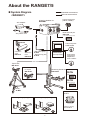
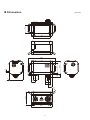
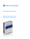
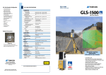
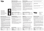
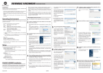
Non-contact 3D Digitizer / Instruction Manual Read and understand all instructions before using. Safety Symbols The following symbols are used in this manual to prevent accidents which may occur as a result of incorrect use of the instrument. Denotes a sentence regarding a safety warning or note. Read the sentence carefully to ensure safe and correct use. Denotes a prohibited operation. The operation must never been performed. Denotes an instruction. The instruction must be strictly adhered to. Denotes an instruction. Disconnect the AC adapter from the AC outlet. Denotes a prohibited operation. Never disassemble the instrument. Notes on This Manual ● Copying or reproduction of all or any part of the contents of this manual without KONICA MINOLTA OPTICS's permission is strictly prohibited. ● The contents of this manual are subject to change without prior notice. ● Every effort has been made in the preparation of this manual to ensure the accuracy of its contents. However, should you have any questions or find any errors, please contact the nearest KONICA MINOLTA-authorized service facility. ● KONICA MINOLTA OPTICS will not accept any responsibility for consequences arising from the use of the instrument. Safety Precautions When using this handware, the following points must be strictly observed to ensure correct and safe use. After you have read this manual, keep it in a safe place where it can be referred to anytime a question arises. WARNING (Failure to adhere to the following points may result in death or serious injury.) Do not use the RANGE7/5 in places where flammable or combustible gases (gasoline etc.) are present. Doing so may cause fire. Do not insert or disconnect the AC power cord's plug with wet hands. Doing so may cause electric shock. Always use the AC adapter supplied as a standard accessory with the RANGE7/5, and connect it to an AC outlet of rated voltage and frequency. Failure to do so may in damage the RANGE7/5, causing a fire or electric shock. Do not disassemble or modify the RANGE7/5 or AC adapter. Doing so may cause a fire or electric shock. Do not bend, twist or pull the AC power cord excessively. Also, do not place heavy object on the AC power cord, or damage or modify the RANGE7/5. Doing so may cause damage to the AC power cord, resulting in fire or electric shock. When disconnecting the AC adapter's plug, always hold the plug and pull it to remove it. Never pull the AC power cord itself. Doing so may damage the AC power cord, causing a fire or electric shock. If the RANGE7/5 will not be used for a long time, disconnect the AC adapter from the AC outlet. Accumulated dirt or water on the prongs of the AC adapter's plug may cause a fire. If there is any dirt or water on the prongs of the AC adapter's plug, remove it. The RANGE7/5 should not be operated if it is damaged, or smoke or odd smells are detected. Doing so may result in a fire. In such situations, turn the power OFF immediately, disconnect the AC adapter from the AC outlet, and contact the nearest KONICA MINOLTA-authorized service facility. CAUTION Take special care not to allow liquid or metal objects to enter the RANGE7/5. Doing so may cause a fire or electric shock. Should liquid or metal objects enter the RANGE7/5, turn the power OFF immediately, disconnect the AC adapter from the AC outlet, and contact the nearest KONICA MINOLTA-authorized service facility. The RANGE7/5 should not be operated if dirt or dust has entered through the vent holes. Doing so may result in a fire. For periodic inspection, contact the nearest KONICA MINOLTAauthorized service facility. Never stare into the laser emitting window. Do not place a lens, mirror or optical element in the passage of the laser beam. Doing so may converge the laser beam, resulting in damage to your eyes, burns or fire. To prevent the above accidents, make sure that a wall or similar which can block the laser beam is located behind the object. (Failure to adhere to following points may result in injury or damage to this instrument or other property.) Be sure to connect the AC power cord plug to an AC outlet that has a grounding terminal. Make sure that the AC outlet is located near the RANGE7/5 and that the AC adapter's plug can be easily connected and disconnected. 1 Do not place the instrument on an unstable or sloping surface. Doing so may result in its dropping or overturning, causing injury. Take care not to drop the instrument when carrying it. Foreword About the packing materials contained in your product package • Please ensure that you carefully keep the packing materials (corrugated cardboard, cushion materials, and plastic bags) contained in your product package. • The RANGE7/5 is a precision measuring instrument. If you transport the RANGE7/5 to our factory for the purpose of maintenance (repair, etc.), you should use the packing materials contained in the product package in order to minimize impact and shock during transportation. If any of the packing materials are lost or damaged, please contact a KONICA MINOLTA-authorized service facility. Notes On Use • We shall guarantee the RANGE7/5 operation at 10°C to 40°C ambient temperature and 65% or less relative humidity. Ensure that the RANGE7/5 operating environment is within this range. • The RANGE7/5 has been calibrated at 20°C. It is recommended that this instrument should be used at a room temperature of 20°C. • The RANGE7/5 has been designed for indoor use. Do not use this instrument outdoors. • Do not use the RANGE7/5 in a place exposed to direct sunlight in summer, or near a heater. The RANGE7/5 temperature becomes much higher than the ambient temperature, causing a fault of the instrument. Use the RANGE7/5 in a well-ventilated place. Do not block the ventilation port. • Do not use the RANGE7/5 in a dusty place, or in a place with high humidity. Otherwise, there may be a fault with the instrument. • Do not strike or apply strong vibration to the RANGE7/5. Otherwise, the instrument may have a fault. • Do not use the RANGE7/5 near a high-rise building or a road with heavy traffic. If the RANGE7/5 and the targets being measured shake, the RANGE7/5 may not obtain accurate measurement results. • Do not overturn the RANGE7/5. Otherwise, the instrument may have a fault. • Do not disconnect any cable while the RANGE7/5 is ON (while Power button is lit yellow-green.) Otherwise, there may be a fault with the instrument. • The RANGE7/5 is a class 2 laser instrument as specified in IEC Publication 60825-1. Handle this instrument properly by observing the instructions given in this manual. • Use the RANGE7/5 at an altitude of 2000 m max. • When you use the RANGE7/5 for the first time, or after transportation, make sure that the lens is securely fastened. If the lens becomes loose, tighten it securely by following the lens exchanging procedure. Care On Storage • The RANGE7/5 should be stored in areas with temperatures of between -10ºC and +50ºC. Do not store it in areas subject to high temperature or high humidity or where sudden changes in temperature or condensation are likely to occur. We recommend storing the RANGE7/5 around room temperature (20ºC) with a desiccant (silica gel etc.). • Do not leave the RANGE7/5 inside a closed car or in the trunk of a car. Under direct sunlight, the increase in temperature can be extreme and may result in malfunctions. • When shipping the product, use the original packing materials in which the product was shipped. The materials will provide protection against vibrations and impact, and also provide some protection against sudden changes in temperature. • The RANGE7/5 should not be stored in areas where there is an excessive amount of dust, cigarette smoke or chemical gas. Failure to adhere to this may result in performance degradation or break-down. • When lenses are not in use, attach the lens and mount caps and store the lenses in the exclusive case. • When storing the RANGE7/5 with lens attached, put the lens cap on the lens. Notes On Cleaning • If the RANGE7/5 needs cleaning, wipe with a soft dry cloth. Never use solvents such as thinner or benzene. • If the lens or laser emitting window is dirty, blow off sand or dust using a blower. If the lens is still dirty, wipe the lens gently with a piece of cleaning paper dampened with a cleaning agent. • In cases of malfunction, do not disassemble the RANGE7/5 or attempt to repair it yourself. Contact the nearest KONICA MINOLTA-authorized service facility. Disposal Method • Make sure that the RANGE7/5, accessories and the packing materials are either disposed of or recycled correctly in accordance with local laws and regulations. 2 Laser Label Indication Warning and instruction labels about the laser RANGE7/5 <FRONT> <REAR> Other warning label 3 About this Manual (Contents) This instruction manual provides the following contents about preparations for use of the RANGE7/5. • Precautions for Use • Part Names and Functions • System Configuration and Accessories • Setup Procedure for Measurement with the RANGE7/5 • RANGE7/5 Measuring Steps (Images) • Measuring Principle of the RANGE7/5 • RANGE7/5 Specifications and Accessories In this manual, illustrations of RANGE7 are used. The product name printed on the front side of RANGE5 is different. Contents and Descriptions Safety Symbols Notes on This Manual Safety Precautions… ………………………………………………………………………………………………………… 1 Foreword… …………………………………………………………………………………………………………………… 2 About the packing materials contained in your product package………………………………………………………………… Notes On Use… ……………………………………………………………………………………………………………………… Care On Storage… …………………………………………………………………………………………………………………… Notes On Cleaning… ………………………………………………………………………………………………………………… Disposal Method… …………………………………………………………………………………………………………………… 2 2 2 2 2 Laser Label Indication………………………………………………………………………………………………………… 3 Warning and instruction labels about the laser… ………………………………………………………………………………… 3 Other warning label… ………………………………………………………………………………………………………………… 3 About this Manual (Contents)………………………………………………………………………………………………… 4 Contents and Descriptions…………………………………………………………………………………………………………… 4 About the RANGE7/5… ……………………………………………………………………………………………………… 5 n System Diagram… ………………………………………………………………………………………………………………… <RANGE7>… ……………………………………………………………………………………………………………………… <RANGE5>… ……………………………………………………………………………………………………………………… n Names of Parts and Functions… ………………………………………………………………………………………………… n Dimensions… ……………………………………………………………………………………………………………………… 5 5 6 7 8 Installation and Setup ………………………………………………………………………………………………………… 9 n Installation ………………………………………………………………………………………………………………………… 9 1) Direct installation on table ……………………………………………………………………………………………………… 9 2) Installation using tripod set (under optional accessories)…………………………………………………………………… 9 3) Installation using the measuring stand set (under optional accessories)… ……………………………………………… 10 n Setup… ……………………………………………………………………………………………………………………………… 11 1) Installing the RANGE7/5………………………………………………………………………………………………………… 12 2) Setting the RANGE7/5’s position relative to the measuring target, and exchanging the lens (RANGE7 only)………………12 3) Connecting the AC adaptor … ………………………………………………………………………………………………… 14 4) Connecting the RANGE7/5 to a PC… ………………………………………………………………………………………… 14 5) Turning power on/off… ………………………………………………………………………………………………………… 15 n About Field Calibration … ………………………………………………………………………………………………………… 16 Measuring Steps (Images)……………………………………………………………………………………………………17 n Installation and Measurement (Image) … ……………………………………………………………………………………… 17 n Shooting and Focusing (Image)…………………………………………………………………………………………………… 18 n Scanning (Image) … ……………………………………………………………………………………………………………… 18 Troubleshooting… ……………………………………………………………………………………………………………19 Other Information………………………………………………………………………………………………………………20 n Measuring Principles… …………………………………………………………………………………………………………… 20 n Specifications… …………………………………………………………………………………………………………………… 21 4 About the RANGE7/5 n System Diagram <RANGE7> AC adapter Standard accessories Optional accessories KONICA MINOLTA RANGE7 Light-receiving lens (TELE, WIDE) Marker sheet trial pack RA-A104 AC power cord (T, W markers: 500 pcs each) Calibration chart RA-105 Calibration sheet RA-A107 3D data processing software RANGE VIEWER Calibration base RA-A106 USB Cable (5m) IF-A22 : Europe only (3m) IF-A18 Personal computer (Commercially available) Reverse engineering /inspection software Rapidform® XOV TM / XORTM Tripod set RA-A121 Platform set for Tripod RA-A151 Measuring Stand Set Marker sheet T RA-A200 RA-A205 (Marker: 2,500 pcs) Marker sheet W RA-A206 (Marker: 2,500 pcs) Dolly VI-B41 Carrying case RA-A213 Rotating Stage (3 kg) Rotating Stage (20 kg) Caster for carrying case RA-A214 5 Standard accessories Optional accessories <RANGE5> AC adapter KONICA MINOLTA RANGE5 Marker sheet trial pack RA-A108 AC power cord (Marker: 500 pcs) Calibration chart RA-A105 Calibration sheet RA-A107 Tripod set RA-A121 Calibration base RA-A106 3D data processing software RANGE VIEWER USB Cable (5m) IF-A22 : Europe only (3m) IF-A18 Personal computer (Commercially available) Platform set for Tripod RA-A151 Reverse engineering /inspection software Rapidform® XOV TM / XORTM Measuring Stand Set Marker sheet W RA-A206 RA-A200 (Marker: 2,500 pcs) Dolly VI-B41 Carrying case RA-A213 Rotating Stage (3 kg) Rotating Stage (20 kg) Caster for carrying case RA-A214 6 n Names of Parts and Functions 1) Carrying handle 3) Laser-emitting Window WARNING 2) Light-Receiving Lens A laser beam is emitted from this port. Do not stare directly into the laser beam. 4) Laser shutter 6) Platform mounting screw hole 5) Rubber sole 7) Power switch 8) AC adapter terminal Laser Label Indication (page 3) 9) USB port (Type B) 1) Carrying handle 2) Light-receiving lens Used to lift or carry the RANGE7/5. (Be sure to hold the RANGE7/5 body with both hands.) Exchange the light-receiving lens for an optimum lens (Tele or Wide lens), depending on the measuring target size and measuring distance. 3) Laser-emitting window A laser beam is emitted to a measuring target from this window. (Do not stare directly into the laser beam.) 4) Lens shutter When the power is switched off, this shutter closes to protect the laser emitting window. 5) Rubber sole Four rubber soles are attached at the bottom of the RANGE7/5. To install the RANGE7/5 directly on a firm table, use these parts. Also, use the calibration chart set during field calibration (under standard accessories); or when mounting the RANGE7/5 to the tripod set, or measuring stand set (under optional accessories), use these parts to set the RANGE7/5 in place. 6) Platform mounting screw hole Screw holes for fastening the RANGE7/5 to the measuring stand platform or tripod platform (under optional accessories). 7) Power switch Turns ON/OFF the RANGE7/5 power supply. 8) AC adaptor terminal Connect the RANGE7/5 AC adaptor plug to this terminal. 9) USB port When connecting the RANGE7/5 to a PC, connect the USB cable (standard accessory) Type B plug. 7 n Dimensions 111 (Unit: mm) 248 141 199.6 48.3 9.1 ø15 20.8 387.9 ø 35 ø61.5 197.7 ø66 57.7 ø74.7 57.7 55 ° 189.6 9 292.4 8 Installation and Setup n Installation This section describes the RANGE7/5 installation procedures and precautions for installation. <Installation procedure> To install the RANGE7/5, you can use the following three methods: 1) Direct installation on a table or like surface (including a measuring table prepared by user) 2) Installation using tripod set (under optional accessories) 3) Installation using measuring stand set (under optional accessories) 1) Direct installation on table The RANGE7/5 can be directly installed on a table or like surface by using the rubber soles at the bottom of the unit. NOTE • Install the RANGE7/5 on a firm, level table. • To install the RANGE7/5 on a table prepared by user, use a firm, level table wide enough to put to completely secure the four rubber soles. • When the RANGE7/5 is directly installed on a table, the RANGE7/5 may not obtain the correct measurement results depending on the position relative to the measuring target. In this case, use of the tripod set or measuring stand set (under optional accessories) is recommended. 2) Installation using tripod set (under optional accessories) Mount the RANGE7/5 to the tripod platform (under optional accessories). NOTE • Before mounting the RANGE7/5, make sure that the tripod platform is properly mounted to the tripod. * For the tripod platform to tripod mounting procedure, refer to the instruction manual with regards to the tripod platform. • When using the tripod set, tighten the lock lever for each part so that the tripod will not accidentally shake. • Install the tripod set on a firm floor. To move the tripod set, slide it slowly with the dolly (under optional accessories). [Mounting procedure] 1) Hold the tripod platform swing plate mounted to the tripod, set horizontally. 2) Hold the handles with both hands, and put the RANGE7/5 on the swing plate. * Among the four rubber soles at the bottom of the RANGE7/5, the two soles on the rear side must fit securely into the swing plate positioning holes. 3) Insert the four screws on the back of the swing plate into the platform mounting screw holes at the bottom of the RANGE7/5, and turn the screws clockwise to tighten them securely. NOTE • When removing the RANGE7/5, perform the above procedure in the reverse order. • Normally, the screws at the bottom of the swing plate will not come off. However, if the screws are forcibly turned from the RANGE7/5 removing position, the screws may come off. 9 3) Installation using the measuring stand set (under optional accessories) Mount the RANGE7/5 to the measuring stand platform (under optional accessories). NOTE • Before mounting the RANGE7/5, make sure that the measuring stand platform is properly mounted to the measuring stand. *F or the procedure on how to mount the measuring stand platform to the measuring stand, refer to the instruction manual for the measuring stand set. • When using the measuring stand, tighten the lock lever for each part so that the measuring stand will not accidentally shake. • Install the measuring stand on a firm floor. Do not step on the leg, or hang on the arm. [Mounting procedure] 1) Hold the measuring stand platform swing plate horizontally mounted to the measuring stand arm. 2) Hold the handles with both hands, and put the RANGE7/5 on the swing plate. * Among the four rubber soles at the bottom of the RANGE7/5, the two soles on the rear side must securely fit into the swing plate positioning holes. 3) Insert four screws on the back of the swing plate into the platform mounting screw holes at the bottom of the RANGE7/5, and turn the screws clockwise to tighten them securely. NOTE • When removing the RANGE7/5, perform the above procedure in the reverse order. • Normally, the screws at the bottom of the swing plate will not come off. However, if the screws are forcibly turned from the RANGE7/5 removing position, the screws may come off. 10 n Setup To execute measurement using the RANGE7, mount an optimum lens depending on the measuring target size and the measuring distance, and install the RANGE7 at an optimum position relative to the measuring target. (No replacement lens for RANGE5.) The following is an example of the ordinary RANGE7/5 setup using the tripod setting (under optional accessories). RANGE7/5 Cable clamp Tripod Set Platform for Tripod Object AC adapter (100V AC main outlet with a grounding terminal) AC power cord RANGE VIEWER USB cable Personal Computer 11 <Setup procedure> This section describes the procedure for installing the RANGE7/5 properly, and completing the preparations for measurement. Make preparations according to the following procedures: 1) Installing the RANGE7/5. 2) Set the RANGE7/5 at a position relative to the proper target, and mount the lens suitable in question as the target of measure. (No replacement lens for RANGE5.) 3) Connect the AC adaptor to the RANGE7/5. 4) Connect the RANGE7/5 to a PC. 5) Turn ON the RANGE7/5 power switch to start warming up the RANGE7/5. 1) Installing the RANGE7/5 The RANGE7/5 can be directly installed on a table by using the rubber soles at the bottom. Also, it can be installed with the tripod set or measuring stand (under optional accessories). When the tripod set or measuring stand are used, the RANGE7/5 orientation can be freely changed (up/down and right/left). This feature is useful for measurement. Memo For installation procedure details, please refer to the description on “Installation”. 2) Setting the RANGE7/5’s position relative to the measuring target, and exchanging the lens (RANGE7 only) Scan Position Adjustment The location and posture of the work and RANGE7/5 can be adjusted so that the two are appropriately positioned for scanning. These adjustments are made by activating the monitoring feature and watching the work in the monitor window. RANGE VIEWER monitor window Receiver lens RANGE7: TELE/WIDE replaceable RANGE5: No replacement lens RANGE7/5 Distance to work 450mm to 800mm X Z Y Click the [Monitor] button to check the work on the monitor window. Work • The origin is set at the sensor position which is Distance to work and work size (Unit: mm) Lens TELE lens WIDE lens Distance 450 800 450 800 X×Y 79×99 141×176 150×188 267×334 Z 54 97 109 194 Memo For RANGE5, please refer to the WIDE lens data. approximately 120 mm behind the center of the lens surface. Therefore, the Z dimension has an offset of around 120 mm applied. Distance to work and work size in MultiFocus mode Lens TELE lens Distance 462 781 X×Y 81×102 138×172 Z 54 97 (Unit: mm) WIDE lens 475 766 159×199 256×320 109 194 Memo For RANGE5, please refer to the WIDE lens data. 12 Changing of Lens (RANGE7 only) Set the RANGE7 at a position proper to the measuring target, and exchange the lens for an optimum one, depending on the measuring target size and the distance between the RANGE7 and the measuring target. NOTE When changing the lens, confirm that the lens number is the same number as the RANGE7 body. Memo RANGE7 needs to warm up for about 20 minutes after being switched ON. It is always possible to change lenses, but if the lens temperature is different from the main body temperature, it may result in inaccurate measurements. To avoid this problem, change lenses before switching the RANGE7 ON, and warm-up the RANGE7 with the lens to be used attached. If the lens must be changed after the RANGE7 has already warmed up, wait at least 5 minutes for the lens temperature to adjust to the temperature of the RANGE7. [Lens exchanging procedure] 1) Turn the lens mounted to the RANGE7 counterclockwise by holding the "mark" lens barrel. After turning the lens to the hit position, pull it out straight slowly. 2) Align the side pin of the lens with the red mark on the RANGE7, and insert the lens straightly according to the inside guide. 3) After inserting the lens to the hit position, turn it clockwise by holding the lens barrel to tighten it securely. NOTE • Remove the lens by reversing the attaching procedure. • Be careful to avoid touching the lens surface when changing lenses. Memo • Grease for lubrication has been applied to the screw for installation of the lens. When the RANGE7 is purchased, the screw of the lens not attached to the RANGE7 is wrapped with a transparent Lens cap sheet for grease protection. Remove this sheet before use. • When removing the lens, attach the mount and lens caps. Mount cap 13 3) Connecting the AC adaptor 1) Connect the AC cable to the AC adaptor for the RANGE7/5. 2)Insert the AC adaptor plug of the dedicated AC adaptor (AC-A324) to the AC adaptor connection terminal on the right of the RANGE7/5 rear panel. 3) Insert the AC cable plug connected to the AC adaptor to a 100 V AC main outlet. NOTE Insert the plug securely to the innermost position. 4) Connecting the RANGE7/5 to a PC 1) Insert the Type B plug of the dedicated USB cable to the USB port on the right of the RANGE7/5 rear panel. Memo The USB connection port of the RANGE7/5 is equipped with the plug hold mechanism. First, when the plug is inserted, it will hit something. Then, you must further insert the plug securely to the innermost position. 2) Insert the end of the USB cable (Type A plug) into the USB port of the PC. NOTE • Insert the plug securely to the innermost position. • During measurement with the RANGE7/5, or during data processing after measurement, do not disconnect the USB cable. 14 5) Turning power on/off 1) Push the white power button in the upper right part of the rear panel of the RANGE7/5. A short beep sounds, the power is switched on, and the power button is lit yellow-green. Power button 2) Warming-up of the RANGE7/5 starts when the laser shutter is opened. Memo • RANGE7/5 needs to warm up for about 20 minutes after being switched ON. • While the RANGE7/5 is warming up, a message that the RANGE7/5 is now warming up will appear on the screen of RANGE VIEWER software. This message will disappear when warming-up of the RANGE7/5 is completed. 3) Push the yellow-green-lit power button again. Two short beeps will sound, the power is switched off, and then the light of the power button will disappear. NOTE • Do not turn the RANGE7/5 off during measurement or data processing after a measurement. • When turning the power OFF, do not unplug the AC power cord from the AC outlet until the power light disappears. 15 n About Field Calibration The figure below shows an example of setting up the RANGE7/5 for calibration using the Calibration Set. Enough space is needed to spread out the sheet. 1280×430 mm Set the calibration chart in the position RANGE7/5 Calibration chart marked on the sheet for the lens being used. Calibration base Memo For RANGE5, place in the position off the WIDE lens. Calibration sheet Do not touch the front side of the chart with bare hands. If dirty, wipe the chart clean with a dry soft piece of cloth. Calibration is easy to understand and perform with the Calibration Wizard. For details, see “5-1. Scanning is done seven times for calibration. Calibration” on p. 70 of the Reference Manual. Position and angle the calibration chart as indicated in the Calibration Wizard. Calibration should be performed in the following cases: • Before using for the first time after purchase. • If the RANGE7/5 has not been used for a few days. • If the ambient temperature during storage or use is drastically different from the ambient temperature at the time calibration was last performed. • If the RANGE7/5 may have been subject to vibrations during shipping or movement. • To achieve higher measurement accuracy. NOTE • The Calibration Chart has been calibrated using the RANGE7/5 unit with which it was shipped. When performing calibration, be sure to use the Calibration Chart with the same number as the RANGE7/5 body. • Before performing calibration, confirm that the lens number is the same number as the RANGE7/5 body. 16 Measuring Steps (Images) n Installation and Measurement (Image) Example of installation on Measuring Stand Set RA-A200 (optional accessory) Example of installation on Tripod Set RA-A121 (optional accessory) 17 n Shooting and Focusing (Image) n Scanning (Image) 18 Troubleshooting If you have some problems when using the RANGE7/5, please refer to the following table to check on the situation. The RANGE7/5 operation is controlled by the 3D processing software “RANGE VIEWER”. The RANGE VIEWER monitors the RANGE7/5 condition, and displays the appropriate messages. Please also refer to the “Error Message” section in the RANGE VIEWER Reference Manual. Symptoms Power is not turned ON. Item to check / Possible causes • Is the AC adapter connected? Corrective actions • Check the AC adaptor and AC cord • Is the AC cord of the AC adapter properly connections. If not connected, do so connected to the main outlet? The indicator does not light yellow when the power switch is • Is the green indicator on the AC adapter properly. • Connect the RANGE7/5 AC adapter to a 100 to 240Vac (50 to 60Hz) main outlet ON? pressed. The yellow indicator went off without turning OFF the power. before use. • Did you disconnect the USB cable during • Connect the USB cable properly, and measurement? turn ON the RANGE7/5 power again. * The RANGE7/5 is connected to a PC using the USB cable, and measurements are controlled by the 3D processing software “RANGE VIEWER”. When the USB cable is disconnected during measurement, the RANGE7/5 power turns off. • Is the AC adapter connected? • Is the AC cord of the AC adapter properly connected to the designated main outlet? • Check the AC adaptor and AC cord connections. If not connected, do so properly. • Connect the RANGE7/5 AC adapter to 100 to 240Vac (50 to 60Hz) main outlet before use. Does not scan • Is the RANGE7/5 properly connected to • Check that the RANGE7/5 is properly a PC using the USB cable? connected to a PC using the USB cable. • Is the lens properly attached? Also check that the USB cable B plug is • Is the RANGE7/5 power turned ON? securely connected to the RANGE7/5 USB connection port. • Properly attach the lens according to object size, or distance to said object. • Confirm that the power button is lit yellow-green when the power button in the upper right part of the rear panel of the RANGE7/5 is pressed. The RANGE7/5 exterior becomes • Is the RANGE7/5 vent blocked? • Do not block the vent. hot * Doing so may cause affect air circulation and cause the internal temperature of the RANGE7/5 to rise. 19 Other Information n Measuring Principles <Basic Principle> The RANGE7/5 uses the light sectioning method to emit a horizontal stripe light through a cylindrical lens to the object. The reflected light from the object is received by the CMOS sensor, and then converted by triangulation into distance information.This process is repeated by scanning the stripe light vertically on the object surface using a Galvano mirror, to obtain a 3D image data of the object. Emitting lens CMOS sensor Galvano mirror Light-receiving lens Laser beam Object <High-Speed Image Processing Circuit> The stripe light is scanned on the CMOS image plane at one horizontal line per frame, and the CMOS is driven so that the block readout start position is shifted one line per frame. Approximately 1400 frames are acquired. • Frame rate: 600 frames/sec. • Block readout: 350 lines Frame The output signal from the CMOS sensor is then converted into a digital signal, which is then subjected to digital signal Memory processing. The processed data is finally transferred to the computer via the USB interface. Frame interline Transfer CCD A/D FIFO DSP Frame Memory Clock Generator CMOS Sensor Galvano Scanner Host I/F Laser Diode A/D FPGA USB Driver USB CPU Driver CPU Data Bus Galvano Scanner Lazer Diodo CPU Driver CPU Data Bus <Time center of gravity and Space center of gravity> With this instrument, 3D images are obtained by calculating the time center of gravity of each pixel of the CMOS sensor. With this method, compared to the space center of gravity, use of the time center of gravity reduces the influence of sensitivity variations of the CMOS sensor pixels and variations in object brightness. 20 n Specifications MODEL NAME KONICA MINOLTA RANGE7 Measuring Method Triangulation by light sectioning method Light-Source Semiconductor laser λ = 660 nm Laser Classification Class 2 (IEC60825-1 edition2) Sensor Name CMOS Photo diode Pixel 1.31 Mega Pixel (1280 x 1024) Measuring Distance (mm) 450 to 800 (Distance from Light-Receiving Lens *1) Light Receiving Lens (Replaceable) TELE / WIDE Lens Measuring Range (mm) MultiFocus Distance X-Y size mode Disabled Z TELE TELE WIDE WIDE 450 800 450 800 79 × 99 141 × 176 150 × 188 267 × 334 54 97 109 194 Meas.pitch of X-Y 0.08 0.14 0.16 0.28 Lens TELE TELE WIDE WIDE 462 781 475 766 81 × 102 138 × 172 159 × 199 256 × 320 54 97 109 194 0.08 0.13 0.08 0.25 MultiFocus Distance X-Y size mode Enabled Z Meas.pitch of X-Y Accuracy (Interglobuler distance)*2 ±40 μm Precision (Z, σ)*3 4 μm Auto Focus available Auto Exposure available Scanning Time about 2 sec. per scan Preview Function available (about 0.4 sec. per scan) Environment Brightness 500 lx or less File Format *4 INPUT/OUTPUT: .rgv, .rvm, .rmk (Original format), OUT only: .stl Output Interface USB 2.0 HighSpeed AC adapter Power Supply 100-240Vac (50-60 Hz), 1.4A External Dimensions (mm) 295 (W) x 190 (H) x 200 (D) * exclude the protruding portion of the lens and handle Weight (kg) about 6.7 Operating Condition 10 to 40ºC (relative humidity 65% or less, with no condensation) -10 to 50ºC (relative humidity 85% or less [at 35ºC] , with no Storage Condition condensation) Remarks (Controlled Method) *1 Controlled via dedicated PC software "RANGE VIEWER" Due to the difference of origins on the measurement reference surface and measurement data, the Z axis coordinate has an offset of about 120 mm for the measuring distance. *2 When the interglobuler distance for the ball bars (2 globes) specified in VDI/VDE2634-2 is measured under the following conditions defined by KONICA MINOLTA OPTICS: Our conditions: Temperature 20±1ºC / Using the TELE lens / Distance 450 mm / Warming up 20 mins. / Using the KONICA MINOLTA OPTICS processing software / With Calibration / Object to be measured: Standard KONICA MINOLTA OPTICS (2 globes) instrument / Position of object to be measured: KONICA MINOLTA OPTICS standard position (10 locations within the measurement space) / Does not cover the uncertainty over the pricing of the standard instrument. *3 Measuring conditions: Temperature 20±1ºC / Using the TELE lens / Distance 450 mm / Warming up 20 mins. / Using the KONICA MINOLTA OPTICS processing software / Object to be measured: KONICA MINOLTA OPTICS reference plain chart / 1σ *4 Using the KONICA MINOLTA OPTICS “RANGE VIEWER” processing software • The RANGE7 includes the eT-Kernel/Compact from sSOL Co., Ltd. 21 MODEL NAME KONICA MINOLTA RANGE5 Measuring Method Triangulation by light sectioning method Light-Source Semiconductor laser λ = 660 nm Laser Classification Class 2 (IEC60825-1 edition2) Sensor Name CMOS Photo diode Pixel 1.31 Mega Pixel (1280 x 1024) Measuring Distance (mm) 450 to 800 (Distance from Light-Receiving Lens *1) Distance MultiFocus X-Y size mode Z Disabled Measuring Meas. pitch of X-Y Range Distance (mm) MultiFocus X-Y size mode Z Enabled Meas. pitch of X-Y 450 800 150 × 188 267 × 334 109 194 0.16 0.28 475 766 159 × 199 256 × 320 109 194 0.08 0.25 Accuracy (Interglobuler distance) *2 ±80 μm Precision (Z, σ)*3 8 μm Auto Focus available Auto Exposure available Scanning Time about 2 sec. per scan Preview Function available (about 0.4 sec. per scan) Environment Brightness 500 lx or less File Format *4 INPUT/OUTPUT: .rgv, .rvm, .rmk (Original format), OUT only: .stl Output Interface USB 2.0 HighSpeed AC adapter Power Supply 100-240Vac (50-60 Hz), 1.4A External Dimensions (mm) 295 (W) × 190 (H) × 200 (D) * exclude the protruding portion of the lens and handle Weight (kg) about 6.7 Operating Condition 10 to 40ºC (relative humidity 65% or less, with no condensation) -10 to 50ºC (relative humidity 85% or less [at 35ºC] , with no Storage Condition condensation) Remarks (Controlled Method) *1 Controlled via dedicated PC software "RANGE VIEWER" Due to the difference of origins on the measurement reference surface and measurement data, the Z axis coordinate has an offset of about 120 mm for the measuring distance. *2 When the interglobuler distance for the ball bars (2 globes) specified in VDI/VDE2634-2 is measured under the following conditions defined by KONICA MINOLTA OPTICS: Our conditions: Temperature 20±1ºC / Distance 450 mm / Warming up 20 mins. / Using the KONICA MINOLTA OPTICS processing software / With Calibration / Object to be measured: Standard KONICA MINOLTA OPTICS (2 globes) instrument / Position of object to be measured: KONICA MINOLTA OPTICS standard position (10 locations within the measurement space)/ Does not cover the uncertainty over the pricing of the standard instrument. *3 Measuring conditions: Temperature 20±1ºC / Distance 450 mm / Warming up 20 mins. / Using the KONICA MINOLTA OPTICS processing software / Object to be measured: KONICA MINOLTA OPTICS reference plain chart / 1σ *4 Using the KONICA MINOLTA OPTICS "RANGE VIEWER" processing software • The RANGE5 includes the eT-Kernel/Compact from sSOL Co., Ltd. 22 9222-A0V8-49 ©2009-2012 KONICA MINOLTA OPTICS, INC. BCEBPF