1
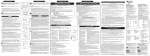
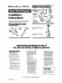
Optional tools and materials
needed for some installations:
Ki+chenAhiB
Installation
Instructions
Proper installation ismr
responsibili~
Read instructtons carefully before begInning
Installation. Make sure you have everything necessary for correct installation.
Tools and materials needed
for installation:
Askabwt
the KItchenAid@ Instant Hot’
water dispenserthe faucet that ccroks as
it pours
Instructions pertaining to risk of
fire, electric shock, or injury to persons.
Important safety
instructions:
7. To reduce the nsk of injury by materials
that maybe expelled by a food-waste
disposer, place the stopper in the
dralnlgrlnd
ps1t1on when gnndlng. Do
rot put the fclowng
Into a disposer:
WARNING. When usfng electnc appliances,
basic precautions should always be
followed, lncludlng the folIowIng
1. Read all the wxtructlons
appliance
a.
b.
C.
d.
before using the
9. To reduce the risk of ,n,ur): close
supew~s~on IS necessary when appliance
15used “ear children.
3. DO not put flyers
disposer
Clam and oyster shells
Drain cleaner
Glass, chlna or plastic
Large, whole bones
e. Metal, such as bottle caps, tin cans,
or alummum foil.
8. W-m not operating a dlsposet, leave the
drain cover in place to reduce the rlskof
objects falling Into the disposer
or hands Into waste
4. Turn the power swtch to the OFF
posItIon before attemptIng to clear a jam
M remove an dJJeCt from the disposer
5. When attemprlng to loosen a jam in a
waste disposer. “se a self sewce lambreaker wrench as described I” Use and
Care Guide
6. Vhen atremptlng to remove objects from
a waste disposer, use long-handled
tongs
or pliers
9. a. GROUNDING
INSTRUCTIONS FOR
CORD-CONNECTED UNITS. This
appliance must be grounded. In the
event of a malfunction or breakdown,
grounding prowdes a path of least
reswance for electnc current to
reduce the risk of electnc shock If this
appliance IS equipped wth a cord
havng an equipment-groundlng
conductor and a grcundlng plug, the
plug must be plugged Intoan
appropriate
Outlet that IS property
Installed and grounded I” accordance
with all local codes and ordinances
DANGER - Improper COnnectIon of
the equipment-groundmg
conductor
can result I” a risk of electnc shock
Check v&h a quaIlfled electncian or
sew~cemw If yw are I” doubt as to
tiether
the appliance is properly
grounded
Do rot modify tie plug
provided wth the appliance - If It WIII
not fit the c&let, have a proper outlet
mstalled by a qwllfled electnc~an.
b. GROUNDING INSTRUCFIONS FOR
PERMANENTLY CONNECTED UNlT5:
This appliance must be connected to
a grounded, metal, permanent wnng
system; cw an equipment-grounding
conductor must be run with the circuit
conductws
and connected to the
equipment-grounding
terminal or lead
on the appliance.
Save these
instructions.
INSTALLER-Please leave lnstallatlon
lnstructlons wth the homeowner or
occupant.
I
For service
@I988 KltchenAd, Inc
Form No/Pan NO 9167/4’211430
information,
call your local KitchenAid
Prepared by KilchenA,d:’
Distributor.
St Joseph, Mich,gan 49085
Prlnred ,n ” S A
Start the in&Nation
Installation
dimensions
Food Waste
Dimenslons
_
Disposer
In Mllllmeters.
3
Remove old
disposer.
Compare your new disposer mountrng
assembly wrth the exrstrng mountrng.
If the mounting assembkes are the same,
complete Steps 3A, 8, D, E.
A. Using a pope wrench, disconnect the drain
lrne &we
rt attaches to the drsposer waste
line prpe
B’ - Distance from bottom of sink to center
Ike of disposer outlet Add 1Q 7 mm tien
sramless steel srnk is used.
C* - Length of waste line pope horn center
IIW of disposer outlet to end of waSte line
me.
IMPORTANT: Plumb waste line to prevent
standrng water in the drsposer motor
housrng.
Check that
all parts were
included.
Drawing
shows Just one model
type.
InaP rins
2
Electrical
supply
Before attemptrng to rnstall electrrcal supply
to your drsposer, you must be very famrlrar
wrth electrical power and proper procedures
If you are not, contact a qualrfred electwan
Thus applrance IS equrpped wrth copper
wires. Use 3-conductor
copper cable rn
accordance with the local code to make
ccnnectrons to the unit.
A Remove the fuse or turn the circurt breaker
to U-e “0W position for the circuit you plan
to use for your drsposer Use a separate
PO-ampere, llS.volt, 63 Hz onty crrcurt for
the drsposer.
If you are nplaclng
a” old disposer,
go to step 3.
For a first tlmc Installation,
connect 15. or
PO-amp, 115~Volt cable from~unctior
box to
swtch.
6. For continuous feed models. Install a 15- of
PO-amp wall swtch above the countertop
and junction box inside c&net as show
Whp swatch and elecmcal wiring can be
obtarned locally) Position titch
in a
corwenrent locatron Connect swtch to
junction box. All wlrlng must comply wkh
locsl codes and ordlnmces.
NO. 14.gauge
wee is the smellest srze wire allowable for
use with a 15-amp crrcurt. No. lQ-gauge
wrre IS the smallest allowable for use wrth
a W-amp crrcurt Go to Step 4.
The drsposer can be rnstalled usrng a power
supply cotd wrth a 3.prong groundrng plug
Th6 type of power supply cord 1sa&able
from local sources
LE-I
B. If old dlspour
mwntlng
Is the sdme a5
your new one, rnsen end of jam-breaker
wench of screwdwer
into right srde of a
disposer mounting ring lug at top Of
drsposer Hold drsposer wth other hand
Turn Jam-breaker wench of SCrWdliW
counterclockw4se
unth lug lanes up with one
of the sink-mwntlrg
assembly scrw6
CAUTION: Hold dlsposcr 4th one hand
while turning to prevent It from frlllng
when the mounting
rmg Is dlsconnccted.
Remove drsposer
Go to Step 3-D.
C. II old disposer mounting
Is different from
your new one, remove the nuts on the
mountrng rrng usrng plrers or an adjustable
wench. Remove old drsposer. You may
need to remove a clamp or burst the
drswser to remove It
D.Tum disposer upside down
electrical plate.
and remove the
E. use a xwwdrrver
to remove the grounding
we. Remove wire nuts horn power
mres Separate dwoser
power wires
km the cable wres Loosen screv.6)
on warn relief and remove cable from the
disposer.
lfold disposer mounting
is the same
es your new disposer mounting,
go to
step 5.
E Loosen screws and remove the mountrng
rrng and back-up rings.. A hammer may be
needed to looSen rings..
G. Push old sink sleeve up through
and remwe
the srnk hole
H.Clean sealant horn smk hole nm using a
xre+.driver
or putty knfe to scrape away all
traces of putty of caulklrg from the sink hole
rim. Hole nm must be as clean as possible
for a gad, watertrght seal.
4
&Use wrench
“P”.Wap.
To install our
sink’s firs Y
disposer :
to looser! nut at top of
1
8
B. Remove nut at top of sink strainer Remove
extension pope.
C. Loosen the large-diameter
nur at the base
of the strarner by placmg the tip of d
screwdwer
on the rldjr of the nut and
gently tapp~nj the wrwdrlver
~0th a
hammer
E. Push the straner assembly up through the
sink hole and remove
5
Clean sink’s
drain line.
If installing in a new home, go to Step 6.
Remove drain trap. Using anaujer, clean out
the horlzcmtal drain pope that run5 from the
trap to the main waste pipe.
6
~wo,‘mg
,om?::?k:p!!ond
rub&r gasket, tin the metal bsck-up ring
(flat side up), up and over sink flange.
B. Holdmj ttx rubber gasket and metal backup nng in place, attxh the mwntlng
ring to
the sleedve wth the three mounting rrnj
screw-s Do Not bqhten screws at this t!me.
D. Remove nut
A
Separate the
mounting
assembly.
Holdlnj the mountlnj assembly with one
hand, “se the other hand to ,nsert,ambreaker wrench Into one of the lugs of the
lower mounting rlnj Turn assemblycounterclockwse and remove
B. Loosen scron mountmg
the/ are level with mountlnj
c. Use ScrewdrIver
assembly until
rung surface
to pry off snap r,ng
C. Push rubber gasket, metal back-up n”g and
mounmg rmg further up sink sleeve. Slrde
snap ring wto srnk sleeve untrl It pops Into
place I” the sleeve groove.
D.Tijhten
mounting scruntil entlre
mounting assembly IS seated evenly and
tkhtlvawnst
sink
A
9
D. Take assembb
a
apart and set aslde
Apply rubber
asket or putty
so sink flange. ,?
The rubber sink flange gasket should alway;
be used where powble
Place rubber
gasket over sink flange Go to Step 7-C
B. If slnkopenmj
does not permit the “se of a
rubber seal, plumb&
putty may be used
Form putty rntoa long roll by roll~nj It
behveen your hands Press roll under sink
flange nm
C. Place flange Into sink drain hole. Fust down
gently, but flrmb to make sure flange sits
evenly over gasket or I” putty
PANEL
B
1D.H
Make
electrical
connections.
Remove electrical plate from the bottom
of the new disposer Pull out the black end
Vmrte electrical wires Locate the green
jroundnj
screw under plate.
8. Insert strain relref Into hole Insert power
supply cable through strain relief. Pull cable
wres through open~nj where dlswser
wres are located. nghten strain relref
screws.
c. Connect power supply cable bwres to the
disposer wires us~nj electrical wire nut5 M
by solderlnj wires together Be SUR to
connectwhiietotiite,andbbckto
black. Wrap wore conratlcns
with
electrical tape. Put wires back inside
drsooser housmq.
10
Check for
proper
grounding.
Electrical
appliance.
7
Attach the
upper
mounting
ground
Do NOT reconnect
main service panel
Is installed.
is required
on this
eletical
CUrTent to
until proper ground
k If the cabk kadlng to the dlswser
has
three wires, attach tine green groundlnj
we to the green groundlng xre.v Go to
Step 10-D.
B. If the cable does NOT have a grounding
wire, attach a length of copper wire (no
smaller than the other cable wire) to the
jreen grcwndmg screw
C. Attach theotherend
of thegrwndmj
wire
to a grounded metal cold water pipe!
DO NOT ground to a gas sUpply line of
hot water supply Ilne.
Use grounding clamp to secure wire to
pipe. If noa-meta or plastrc pipe IS used in
water connections or water supply, you must
have a qwlified electrtcian install a proper
ground.
1)s
,,
,
D. Check to see if you Iwe a water meter in
p.rr home. To have a grounded water pipe,
dw meter must hewe a wire clamp to either
side of the meter You can ground the water
pipe b securely clampng a length of No. 6
copper wire for PO0 amp service (of less) to
tare metal as show. Use grounding clamps,
wtified
by C.SA, to attach wire to p&.x
G. If dnln Is too short, measure how far
trap outlet IS horn tube and buy a drain trap
extension wth a slip nut. Install trap
eltenslon.
11
O.ptional
$slsh~her
H. ~hrn ~r%s, tljhten the slip nut on the trap.
For double sinks, we recommend
use Of
separate traps for disposer and second
sink.
connection
n you do not plan to connect
a
dishwasher
drain to the disposer,
Step 1%
14
go to
Optional:
Connect to
dishwasher drain.
lay disposer on its side. Insert top of
scravdwer
at an angle Into dran hole
opening. Tap screwdrwer wltJ- hammer until
molded plug papsout. Remove loose plug
from dlsooser
If you do not plan to conneCt a
dishwasher
drain to the disposer,
to Step 15.
Make sure connections
local plumbing
codes.
With
A. A dIshwasher drain connectcx kit may be
purchased from a hardware stow Use worm
gear hose clamp on dlshwasher cOnrrzct!On
to mounting
assembly.
Remove clamp or fining from end of
dishwasherdran
hose
A
LB f3-e dIsposerand
posita? It so that the
dispowi
three mountlnj ears are lined up
under tk ends of the sink mounting
assembly screws.
B. Holdanj the disposer I” place, turn the
locrer mounting rng wth edrs to the rI jht
until all thnc ears IoCk Into place I” the
mountmj assembly The dwoser wll now
hang by Itself The mounting ring WIII be
locked I” place later.
gg;p
13
waste line
pipe to drain trap.
A.
Comply
go
Remwe wry focelgn materials that may
have dropped InsIde the dwoser grIndIng
chamber
D. Insert the jsskecet Into the dispxer
dlsclwje
outlet Gasket will be held I” place by rhe
waste IIM pipe flange Place flange Over
waste Ime pope Secure flange and waste
line pipe to d1spae.r with scre&)
prwlded.
C. lnsat one end of the plastic tube Into the
coupler and fasten wth Pp mm clamp.
D. Slip the jear hose clamp over the
dahwasixrdrain
hose pushlng It back
51-76 mm. Slip drain hose over plastic tube
Slide clamp in place and tIghten.
B. Turn the dqxserarwnd.
Compare your
dlspxer waste lne pope wlti the two types
illustrated in C and D. Attach waste line
pipe as specified.
C. If xat already assembled, place the gasket
cwer the end of waste Ione pipe. Gasket must
be nstalled as shown to prevent laklnj
Insert tube into disposer opening Place
flange Over waste lne pipe and gasket
Secure flange to dlsposermth
screw
provded.
8. Slide large end of rubber coupler over
disposer inlet tube Fasten coupler to
dlsposerwth
clamp prowded
Be sure to tlghten
all three clamps.
15
lock
disposer
in place.
lnserl screadrwer of Jam-breaker wench
tnto left <lde of a dwxxpr
mnuntlnq Iuq
at the top of the dqxxer.
Turn screwdrIver
orjam-breaker wench
to rljht until
dlscoser is locked firmlv I” olace.
..__._--_ _-._r___ _. _ .~
C.
16
proper
operation.
A Slowly run water through unit Then place
stopper
E.Rotate disposer until waste line pipe all jns
wth drain trap.
Make sure all connections
local plumbing
codes.
compty
with
F. If tube Is too long, w off excess tubing
ml- a hackad
Make sure cut IS clean and
straight.
PANEL
c
seal in pasWan and fill wk.
8. Remove stopper and permit water to flow
Check for leaks at all plumbang connections.
If there IS a leak, tlghten the connection at
that pomt
C. Turn water on Run dispenser for one mwte.
Check that disposer IS operatlng correctly
Check for l&z at all plumblng connectlom
again. If there IS a lea& tI jhten the
coanectnn
at that pant