1
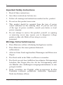
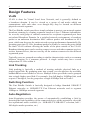
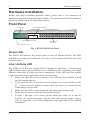
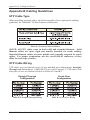
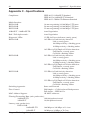
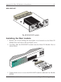
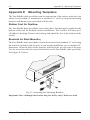
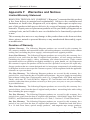
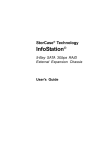
KINGSTON TECHNOLOGY FAST ETHERX 16-PORT, 24-PORT & 32-PORT 10/100TX RACK-MOUNTABLE FAST ETHERNET SWITCH USER’S GUIDE MODEL(S): KNS1650/R KNS2450/R KNS3250/R i Kingston Technology’s Fast EtheRx 16-Port, 24-Port, & 32-Port 10/100BASE-TX Rack-Mountable Fast Ethernet Switch User’s Guide Part No. 4460186-001.A00 Kingston Technology Company 17600 Newhope Fountain Valley, CA 92708 (714)435-2600 www.kingston.com KNS3250/R Users Guide - Rev. A00 Kingston Technology Company ii Important Safety Instructions 1. Read all these instructions. 2. Save these instructions for later use. 3. Follow all warnings and instructions marked on the product. 4. Do not use this product near water. 5. This product should be operated from the type of power source indicated on the marking label. If you are not sure of the type of power available, consult your dealer or local power company. 6. Do not attempt to service this product yourself, as opening or removing covers may expose you to dangerous voltage points or other risk. Refer all servicing to service personnel. Wichtige Sicherheitshinweise 1. Diese Hinweise sollten vollständig durchgelesen werden. 2. Diese Hinweise für einen späteren Gebrauch aufbewahren. 3. Allen auf dem Gerät angebrachten Warnungen und Hinweisen folgen. 4. Das Gerät nicht in der Nähe von Wasser verwenden. 5. Das Gerät nur mit dem Aufkleber bezeichneten Netzspannung betreiben. Bei Fragen über die Art der Netzspannung sollte der Händler oder dasEnergieversorgungsunternehmen zu rate gezogen werden. 6. Nicht versuchen das Produkt selbst zu reparieren. In allen Produkten existieren gefährliche elektrische Spannugen. Nicht das Gehäuse öffnen. Kingston Technology Company KNS3250/R User’s Guide - Rev. A00 iii TABLE OF CONTENTS Introduction......................................................................................................1 Special Features .................................................................................2 Package Contents ...............................................................................3 Design Features..................................................................................4 Hardware Installation.......................................................................................6 Front Panel .........................................................................................6 Rear Panel ..........................................................................................7 Software Installation ........................................................................................8 Switch Conguration Utility............................................................................8 Device Conguration Main Screen....................................................8 Device Conguration Properties ......................................................11 System ................................................................................11 Port .....................................................................................13 Trunk Assignment ..............................................................15 VLAN.................................................................................19 Explicit Address Table........................................................22 Using the Switch Conguration Utility .........................................................24 Editing a Conguration File.............................................................24 Sending the Current Conguration to the Switch ............................25 Assigning Trunks and Setting VLAN Groups .................................27 Troubleshooting ............................................................................................33 Appendices Appendix A Pin Assignments...........................................................36 Appendix B Cabling Guidelines ......................................................37 Appendix C Specications...............................................................40 Appendix D Fiber FX Modules and Installation..............................42 Appendix E Mounting Templates ....................................................44 Appendix F Product Warranties and Notices ...................................45 Limited Warranty Statement...............................................45 Duration of Warranty..........................................................45 Free Technical Support.......................................................46 Disclaimers.........................................................................46 F.C.C. Certication.............................................................47 CE Notice ...........................................................................47 C-Tick Certication............................................................47 KNS3250/R Users Guide - Rev. A00 Kingston Technology Company iv Kingston Technology Company KNS3250/R User’s Guide - Rev. A00 Introduction 1 Introduction Intended Audience: This manual assumes that the user has a general working knowledge of networking principles and architecture and is familiar with network systems in general. Congratulations on the purchase of your new Kingston Fast EtheRx 10/100BASE-TX Rack-Mountable Fast Ethernet Switch. There are three models available, the KNS1650/R, the KNS2450/R and the KNS3250/R, 16-ports, 24-ports and 32-ports, respectively. The Fast EtheRx Switch is a high-performance 10/100BASE-TX switch ideal for the small-to-medium businesses. The Fast EtheRx Switch has sixteen (16), twenty-four (24) or thirty-two (32) UTP ports (depending on model) that auto-negotiate speed detection for 10/100BASE-TX and half-duplex / full-duplex mode operation. The Kingston Fast EtheRx Switch allows standard 10BASE-T Ethernet networks to communicate with 100BASE-TX Fast Ethernet networks and to segment both 10Mbps and 100Mbps networks. The KNS1650/R, KNS2450/R, and KNS3250/R switches also provide additional features such as VLAN, link trunking, broadcast storm control, secure mode trafc ltering and ow control. The Fast EtheRx Switch complies with IEEE802.3u 100BASE-TX, IEEE802.3i 10BASE-T, IEEE 802.3x and IEEE802.3 CSMA/CD Ethernet Standards. The Fast EtheRx Switch may be used in both standard desktop and 19” rackmount installations (using the mounting brackets provided with the unit). For easy recognition of network status and troubleshooting, the front panel includes a variety of diagnostic LEDs including Power, 100TX Speed Detection, Link, Receive, Transmit, Collision, and Full-Duplex status. For the remainder of this manual, the KNS1650/R, KNS2450/R, and KNS3250/R will be referred to collectively as the Fast EtheRx Switch. KNS3250/R User’s Guide - Rev. A00 Kingston Technology Company 2 Model Types Model Types Fast EtheRx 10/100TX 16-Port VLAN/Trunking Switch POWER FX Module LINK / ACT = FDX / COL = 10 Mbps COL 100 Mbps FDX 1/FX1 2/FX2 3 4 5 6 7 8 9 10 11 12 2/FX2 4 6 8 10 12 14 16 18 20 22 24 13 14 15 16 LINK / ACT 1/FX1 2/FX2 3 4 5 6 7 8 10 12 14 8 9 10 11 20 22 12 13 14 15 16 FDX / COL KNS1650/R Fast EtheRx 10/100TX 24-Port VLAN/Trunking Switch POWER 2/FX2 4 6 16 18 24 FX Module LINK / ACT 100 Mbps 10 Mbps FDX / COL 1/FX1 3 5 7 9 11 13 15 17 19 21 23 LINK / ACT FDX COL FDX / COL 1/FX1 KNS2450/R Fast EtheRx 10/100TX 32-Port VLAN/Trunking Switch POWER LINK / ACT 2/FX2 4 6 8 10 12 1/FX1 3 5 7 9 11 14 16 18 13 15 17 20 22 24 26 19 21 23 25 28 30 27 29 32 3 5 7 9 11 13 15 17 19 21 23 2/FX2 4 6 8 10 12 14 16 18 20 22 24 26 28 30 32 1/FX1 3 5 7 9 11 13 15 17 19 21 23 25 27 29 31 FX Module FDX / COL LINK / ACT KNS3250/R 100 Mbps 10 Mbps FDX 31 FDX / COL COL Fig.1 - KNS1650/R, KNS2450/R, & KNS3250/R Special Features • Provides automatic switching function between 100BASE-TX and 10BASE-T networks. • Sixteen (16), twenty-four (24), or thirty-two (32) auto-negotiating ports for 10/100Mbps operation. • Trunking capabilities, • Supports 16, 24, or 32 port-based VLANs. • 16, 24, or 32 UTP ports that auto-negotiate 10/100Mbps operation. • Auto-negotiates full- or half-duplex operation. • Store-and-Forward switching approach to minimize re-transmission of faulty packets. • Filtering/Forwarding rate of 148,800 packets per second at 100Mbps. • Filtering/Forwarding rate of 14,880 packets per second at 10Mbps. • 1K active address entry table per device with self-learning and table aging. • 2 MB packet buffer per eight ports. Kingston Technology Company KNS3250/R User’s Guide - Rev. A00 Package Contents 3 Package Contents Your Fast EtheRx package should contain the following items: q One of the following model Fast EtheRx switches: • KNS1650/R • KNS2450/R • KNS3250/R q AC Power Cord q Kingston Switch Conguration Utility oppy diskette q Conguration Cable q Mounting kit including: (2) Angle Brackets (4) Mounting Bracket Screws (4) 10/32” Rack-Mount thumb screws (4) Rubber Feet q User’s Guide If any of the items are missing or damaged, please contact your Kingston dealer for a replacement. Be sure the items you receive are genuine Kingston Technology products. If the Kingston name and logo are not on the front panel of your unit, it’s not a genuine Kingston product. KNS3250/R Users Guide - Rev. A00 Kingston Technology Company 4 Design Features Design Features VLAN VLAN is short for Virtual Local Area Network, and is generally dened as a broadcast domain. It can be viewed as a group of end nodes which can communicate with each other even though they may be located on different physical network segments. The Fast EtheRx switch provides a simple solution to protect your network against broadcast storming by creating segments based on Layer 2 Ethernet information. As a result, each group of stations connected to a seperate segmented port form an isolated Broadcast Domain. In a switched network environment, a broadcast packet or an unknown destination MAC address packet will broadcast to ALL ports, which can decrease the entire network system performance dramatically. By grouping ports into VLANs, broadcast packets will only be sent to the ports within the same VLAN without effecting the trafc of the ports outside of the VLAN. Broadcast sharing ports can be used to connect servers and other common services, such as Internet access, that are used by all the stations connected to the different segmented ports. Typically users are grouped according to similar characteristics such as a common business function or a common protocol. A single switch may have several independent VLANs within it. Link Trunking Link trunking is basically a method of treating multiple physical links as a single logical link. By grouping ports into a trunk, you can increase the available bandwidth between switches or servers. Multiple lower speed links can be grouped into a single higher speed link. For example, four full-duplex 100Mbps link, such as ports 1 through 4, can be grouped as a single 800Mbps link as Trunk 1. Switching Function The Fast EtheRx Switch is basically designed to bridge Standard 10BASE-T Ethernet networks to 100BASE-TX Fast Ethernet networks and to segment 10Mbps or 100Mbps network segments. Auto-Negotiation Auto-Negotiation provides the means of automatically establishing a link by detecting the link capabilities of the connected device on the network to select the best operational mode available (i.e. 100BASE-TX/10BASE-T selection, half- / full-duplex mode operation, etc.) Kingston Technology Company KNS3250/R User’s Guide - Rev. A00 Design Features 5 Full-Duplex Full-Duplex transmission means that dedicated inbound and outbound channels are established for bi-directional transmission of data. This allows the collision detection mechanism (CSMA/CD) to be by-passed, thus decreasing transmission delay normally caused by listening, collisions, and packet resends when operating in half-duplex mode. Store-and-Forward Switching The Fast EtheRx Switch uses a packet-forwarding method called Store-andForward, which minimizes the re-transmission of faulty data packets. This means that the Fast EtheRx Switch can store the incoming frame in an internal buffer and check the packet for errors before sending it out to the destination port. If the frame does contain errors, it will be discarded and then retransmitted. Flow Control In half-duplex mode the Fast EtheRx Switch implements a collision-based backpressure ow control mechanism that reduces the risk of data loss at congested ports. This is accomplished by forcing a collision with the data frames on all ports once the free-buffer queue has reached the pre-set minimum. In full-duplex mode the Fast EtheRx Switch implements the IEEE 802.3x ow control mechanism. This is accomplished by sending a PAUSE packet on a port when the number of buffers allocated to this port exceeds the pre-set minimum. KNS3250/R Users Guide - Rev. A00 Kingston Technology Company 6 Hardware Installation Hardware Installation Before you begin installing network cables, please take a few moments to familiarize yourself with Fast EtheRx Switch. The functions on the front and rear panels are illustrated in the following sections. Front Panel Fiber FX Module (Optional) Power LED Fast EtheRx 10/100TX 32-Port VLAN/Trunking Switch POWER LINK / ACT 2/FX2 4 6 8 10 12 14 16 18 20 22 24 26 28 30 32 2/FX2 4 6 8 10 12 14 16 18 20 22 24 26 28 30 32 1/FX1 3 5 7 9 11 13 15 17 19 21 23 25 27 29 31 FX Module FDX / COL LINK / ACT 1/FX1 3 5 KNS3250/R 7 9 11 13 15 100 Mbps 17 19 21 23 25 10 Mbps 27 FDX 29 31 FDX / COL COL Full Duplex /Collision LEDs Link /Activity LEDs 10/100BASE-TX UTP Ports Fig. 2 KNS2450/R Front Panel Power LED The PWR LED indicates the power status of the Fast EtheRx Switch. The LED will light up steady green when the AC power cord is connected to the unit from a power source. Link / Activity LED The LINK/ACT LED uses a single LED to display two functions. A steady green light indicates that a good link has been established, and a ashing green light indicates when data is being received or transmitted. If the LED does not display solid green indicating a good link, check the following: 1. Make sure that the power is turned on for both the Fast EtheRx Switch and the attached device. 2. Verify that the drivers for the network adapter have been loaded on the PC. Some network adapters require that the driver be loaded before establishing a proper link. 3. Make sure the cable is wired properly and connected on both ends. 4. Make sure the correct cable type has been selected. 5. If steps 1 through 4 are correct, please check the cable, as it may be defective or wired incorrectly. Replace the cable and try again. Please refer to Appendix A for Pin Assignments and Appendix B for Cabling Guidelines. Kingston Technology Company KNS3250/R User’s Guide - Rev. A00 Hardware Installation 7 Full Duplex and Collision LED The FDX/COLL LED uses a single color LED to display two functions. A solid green light indicates that Full-Duplex operation has been detected. A ashing amber light indicates that a collision has occurred in half-duplex mode. FullDuplex mode is auto-negotiated on all UTP ports. Fiber FX module port (optional) The ber FX module port can be used with an optional MT-RJ, ST, or SC ber module. Port 1 & 2 on the switch are associated with this module. If the optional module is used, then port 1 & 2 on the switch can not be used. For more details on the modules and instructions on installing them, please refer to Appendix D - Fiber FX Modules and installation. 10/100TX UTP Ports The Fast EtheRx Switch has 16, 24, or 32 (depending on model) UTP ports that auto-negotiate both 100BASE-TX and 10BASE-T connections, as well as half- or full-duplex operation. Rear Panel CONFIGURATION PORT Configuration Port 100-240VAC 50-60Hz .07A MAX AC Power Connector Fig.3 - Rear Panel AC Power Connector The Fast EtheRx Switch uses a 100-240VAC internal power supply. Connect the AC power cord from the back of the unit to an AC electrical outlet. Conguration Port The Fast EtheRx Switch can be managed using the Kingston Switch Conguration Utility by connecting the conguration cable from the Conguration Port to the parallel port on the back of your host computer. KNS3250/R Users Guide - Rev. A00 Kingston Technology Company 8 Software Installation Software Installation The Fast EtheRx Switch has several advanced features which can be congured from a Windows 95, 98, NT or 2000 workstation using the provided conguration cable. The software utility allows for VLAN, link trunking, broadcast storm control, secure mode trafc ltering and ow control conguration. The switch conguration software can only be installed on a Windows 95, 98, NT or 2000 system. To install the software, follow the directions below: 1. Insert the Switch Conguration Utility diskette into the oppy disk drive. 2. Go to the Start menu and select Run. 3. Type in A:\SETUP and click OK. 4. Follow the on-screen prompts to complete the installation process. Switch Conguration Utility Upon launch, the Device Conguration main screen contains will appear as shown below. Device Conguration Main Screen File This option brings up the default conguration settings for the currently selected device type. Kingston Technology Company KNS3250/R User’s Guide - Rev. A00 Kingston Switch Configuration Utility 9 Use this option to open a previously saved conguration le. Save the current conguration to a switch conguration le. Save the current conguration with another le name. Device Type Choose the type of device that is connected for conguration. There are six types which can be selected, the 16, 24 and 32 port models, with or without the ber option. Use the properties button to begin configuration settings. A window with 5 different configuration tabs will be brought up. After modifying the switch configuration, the settings can be written to the device if desired. Configuration data can also be viewed by selecting this option after selecting Read. Printer Port I/O Address This option should be used to select the Input /Output Range associated with the printer port on your computer. To nd out what the setting should be follow the procedure below: 1. Go to Start, Settings and select Control Panel. 2. Double click on the System icon. 3. Go to the Device Manager. 4. Open up the Ports (COM & LPT) heading by click on the plus sign next to the heading. 5. Highlight the Printer Port (LPT1) and click on the Properties button. 6. Go to the Resources tab and the Input/Output Range should be displayed. This is the value which needs to be selected in the Switch Conguration Utility. KNS3250/R Users Guide - Rev. A00 Kingston Technology Company 10 Kingston Switch Configuration Utility Use this button to save the current conguration data to the device. After a successful write operation, the device automatically resets and initializes the new conguration. If the write operation fails, check the following: • Verify the conguration cable is well connected. • Ensure that the conguration cable is connected directly from the PC to the Switch. If any other devices are connected to the PC’s printer port, please disconnect them before attempting the conguration of the switch. • Check the host PC to verify that the drivers for the Printer Port (LPT1) are installed correctly. • Make sure the I/O address selected in the Printer Port I/O Address eld matches the actual setting on the host PC. Use this button to read the conguration data from the device. If the operation is successful, the current conguration will become _Inside_Device_Conguration. This button will write the factory default settings to the switch. Use this button to quit the Switch Conguration Utility. Kingston Technology Company KNS3250/R User’s Guide - Rev. A00 Kingston Switch Configuration Utility 11 Device Conguration Properties System Parameters adjusted in this window will control overall system performance. SuperMAC • Enable: When a collision occurs, the port on which the collision occurs will perform a more aggressive back off algorithm of up to 3 slots. • Disable: This is the default setting, when a collision occurs, the device will perform the IEEE802.3 standard exponential backoff algorithm. Aging Control • Enable: By default this option is enabled and set with an aging time of 255 seconds. When enabled, learned MAC addresses are discarded after the aging time has been reached. The aging time can be set between 1 and 510 seconds. • Disable: The Fast EtheRx Switch will retain the learned source MAC addresses for each port. Only dynamically learned addresses will be aged. No explicit (static) entries will be aged out. KNS3250/R Users Guide - Rev. A00 Kingston Technology Company 12 Kingston Switch Configuration Utility Aging Time The address-aging timer is built in to the table aging process. The minimum time is 1 second and the maximum is 510 seconds. 255 is the default value, if the number exceeds 255 it must be an even number. Broadcast Storm Control Threshold The Broadcast storm control function limits the number of consecutive broadast packets for each port that has Broadcast Storm Control enabled. The broadcast packets are stored in the buffer and sent to the other ports one by one. In the buffer, when the number of stored broadcast packets exceeds the specied threshold, the device will discard the consecutive incoming broadcast packets until the number of stored broadcast packets is below the threshold. The assignable values are 16, 32, 48 and 64 with 64 being the default. Description This is basically a comment section for notes by the user. Up to 2048 characters can be written. This description can only be saved and read from the disk le, the information is not stored on the device itself. Kingston Technology Company KNS3250/R User’s Guide - Rev. A00 Kingston Switch Configuration Utility 13 Port Individual port parameters are congured from this window. Select the port from the window on the left hand side and then modify the parameters on the right. Use the Apply to Other Ports button to assign the same setting to other ports. Port Selection Designates the port to be congured. Security • Enable: Packets which result in security violations at the designated port will be discarded. Security violations would happen if a packet is received from an unknown source MAC address or a source MAC address learned previously from another port. Once enabled, the device will disable address learning and the aging process for this port. Users should add the MAC address of the workstation connected to this port to the address table if they do not want the packets to be discarded. • Disable: The forwarding decision made about packets received from the port will not involve source MAC address checking. This is the default option. KNS3250/R Users Guide - Rev. A00 Kingston Technology Company 14 Kingston Switch Configuration Utility Address Learning • Enable: This option is enabled by default, which will cause the MAC address of the source of a packet to be learned. • Disable: When disabled, the MAC address of the source of a packet from this port will not be learned. Broadcast Storm Control • Enable: If the accumulated consecutive broadcast packets in the input buffer of a port is over the threshold specied by the value of the Broadcast Storm Control Threshold on the System Page, new incoming broadcast packets will be discarded until the number has been reduced below the threshold. • Disable: Disabled by default, this option ensures the broadcast packet will not be throttled. Full Duplex Flow Control • Enable: Enabled by default, this option allows the 802.3x full duplex ow control mechanism. • Disable: When disabled, the 802.3x ow control mechanism is not used in full duplex mode. Auto-Negotiation • Enable: Enabled by default, this option allows the port to determine the Data Rate and Duplex Mode of the attached device. • Disable: Disabling this option allows the user to specify the Data Rate and Duplex Mode settings manually. Note: If using the port with the ber (FX) interface, this option is disabled. Data Rate The user may specify the data transmission rate for the selected port. Note: If using the port with the ber (FX) interface, this option is xed at 100Mbps. Duplex Mode The user may specify full duplex or half duplex mode for this port. Apply to Other Ports When the Apply to Other Ports button is selected, a popup window will appear allowing you to select any other ports that you wish to have the same conguration as the currently selected port. Kingston Technology Company KNS3250/R User’s Guide - Rev. A00 Kingston Switch Configuration Utility 15 Trunk Assignment The Kingston KNS1650R, KNS2450R, and KNS3250R switches support link aggregation/trunking. Trunking is a method of grouping multiple physical links as a single logical link. The benet is to be able to group multiple lower speed links into one high speed link for bandwidth aggregation. For instance, four full duplex 100Mbps links, such as port 1-4, could be grouped into one 800Mbps link for Trunk 1. Trunking is most commonly used between the switch and server or between two switches. See the chart below for the maximum number of trunks per switch: Switch Model Number of Trunks KNS1650/R 16 Port Switch Up to 4 Trunks KNS2450/R 24 Port Switch Up to 6 Trunks KNS3250/R 32 Port Switch Up to 8 Trunks Each port based trunk can have between 2-4 trunk ports as members of the trunk. MAC Address based trunks must have 4 trunk ports per trunk. KNS3250/R Users Guide - Rev. A00 Kingston Technology Company 16 Kingston Switch Configuration Utility Load Balancing Method In a multiple link trunk, the links within a trunk should have an equal amount of trafc in order to achieve maximum efciency. Thus, some sort of load balancing amongst the links of a trunk must be deployed. The Kingston KNS1650/R, 2450/R, and 3250/R switches support MAC address based and port based balancing methods. Using these methods, any packet with a trunk destination received by the switch can be forwarded to a proper trunk port. After choosing one method, the user must specify the relative load-balancing mapping to complete the conguration of the trunk port load balancing. Trunk Selection, Trunk Port Assignment Place checkmarks in the boxes of the desired trunk and check the desired trunk port assignments per trunk. Trunk: A Trunk is a group of Trunk Ports grouped together. Port Based Trunk: Each Port Based Trunk may have 2, 3, or 4 Trunk Ports. MAC Address Based Trunk: Each MAC Address Based Trunk must contain 4 Ports. Trunk Ports: A port assigned to a Trunk. The Trunk Ports are setup in groups of 4 and must be selected based on the groups. For example, Trunk 1 can only contain Trunk Ports 1, 2, 3, or 4. Load Balancing Mapping - MAC Address Based When the switch receives a packet with a trunk destination, it will automatically forward the packet to a trunk port based on the source MAC address (SA) and destination MAC address (DA) of the packet. The device uses two bits from SA and DA to map to four trunk ports. The user can select which two bits should be used for mapping: [1:0] Uses bit 1 and 0 for mapping. [3:2] Uses bit 3 and 2 for mapping. [5:4] Uses bit 5 and 4 for mapping. [7:6] Uses bit 7 and 6 for mapping. Each MAC Address contains 6 bytes of data, the last byte is taken from the source MAC address (SA) and the last byte from the destination MAC address (DA). Each byte contains 8 bits of data and the user can determine which two bits of the last byte are used to map the trunk port. See the example on the following page: Kingston Technology Company KNS3250/R User’s Guide - Rev. A00 Kingston Switch Configuration Utility 17 Sample source MAC address Sample destination MAC address 00:C0:F0:1C:23:48 00:C0:F0:22:32:51 Last Byte The byte is in hexadecimal format, the chart below shows the binary value and the bit numbers: Byte = Bit Data Bit Number: 76543210 Last byte of source MAC address (SA) 48 01001000 Last byte of destination MAC address (DA) 51 01010001 The mapping rule is described below: 1. The two bits selected by the user for mapping will result in an odd or even value assignment. Exclusive Or (XOR) Values Bit 1 Bit 2 Bits Selected Value 0 0 0 XOR 0 = 0 [Even] 0 1 0 XOR 1 = 1 [Odd] 1 0 1 XOR 0 = 1 [Odd] 1 1 1 XOR 1 = 0 [Even] 2. Four combinations of the result are mapped to four trunk ports: Source Address Destination Address Trunk Port Odd Odd Trunk Port 1 Odd Even Trunk Port 2 Even Odd Trunk Port 3 Even Even Trunk Port 4 For example, if the user species bit 1 and 0 for mapping and Trunk 2 is assigned, the packets would be sent to the third Trunk Port of Trunk 2 (which would be Port 7). KNS3250/R Users Guide - Rev. A00 Kingston Technology Company 18 Kingston Switch Configuration Utility Load Balancing Mapping – Port Based The port-based load balancing method is an explicit port assignment scheme. It requires that all other ports are assigned to a specic link (trunk port) in the trunk. When the switch receives a packet with a trunk destination, it will automatically forward the packet to a trunk port based on the port it came from. First select a trunk, then click its Port Based button on the right hand side of the screen under Load Balancing Mapping. The Port Based Trunk Port Mapping for Trunk x window will appear as shown below. Click the radio buttons to map each port to one of the trunk ports. All assignments must be completed before it will allow you to close the window. After that, the status will display ‘ok’ on the right side of the Port Based button. If the status ‘not yet’ is displayed, then the load-balancing mapping has not been completed. Kingston Technology Company KNS3250/R User’s Guide - Rev. A00 Kingston Switch Configuration Utility 19 VLAN This window allows users to dene VLAN membership by groups of device ports. Any individual port or trunk can be a member of a VLAN group. A VLAN group is basically a broadcast domain, but any port/trunk is not limited to belonging to only one VLAN group. The forwarding rule is that packets from the source port/trunk will only be forwarded to a destination port/trunk within the same VLAN group. That is, a broadcast/multicast packet will be forwarded to all ports/trunks within the same VLAN group(s) of the source port/trunk except the source port/trunk itself. Unicast packets will be forwarded to the destination port/trunk only if the destination port/trunk is in the same VLAN group as the source port/trunk. Flood Control Within a VLAN, the ood control function is provided to decide what to do with incoming unicast packets with unknown destination MAC addresses. Enable: Packets received with an unknown unicast destination address (DA) will be forwarded to the specied out-link in the same VLAN group. But if the source port (trunk) belongs to more than one VLAN group, then the packet will only be forwarded to one of the outlinks. KNS3250/R Users Guide - Rev. A00 Kingston Technology Company 20 Disable: Kingston Switch Configuration Utility This option is selected by default. Packets received with an unknown unicast destination address (DA) will be forwarded to all ports (except the receiving port) within the same VLAN groups that the received port (trunk) belongs to. Flood control is available only when at least one VLAN group is assigned. And the out-link port must be assigned when ood control is enabled for proper operation. When ood control is enabled, each VLAN group must choose a member as its out-link. If some VLAN groups have overlapped members, one of these members should be chosen as the out-link. If a port (or trunk) belongs to more than one VLAN group, packets that it receives with an unknown destination address (DA) will only be forwarded to one of the out-links of those VLAN groups that it belongs to. VLAN Group The list box shows all dened VLAN groups of the system, and each row is a group. Any individual port or trunk can be a member of a VLAN group, and each group comprises at least two members. One of the members is to be chosen as its out-link. If ood control is disabled, the Out-link column will not appear. To remove the current highlighted group, press the Delete button. Press the Add button to add a new group. To modify settings, select the Modify button or double click the current highlighted group to modify its content. While adding or modifying a VLAN group, the dialog Modify the VLAN Group (or Add a New VLAN Group) as below will popup for user to specify its content. Kingston Technology Company KNS3250/R User’s Guide - Rev. A00 Kingston Switch Configuration Utility 21 The group count is not limited. Users can specify n VLAN groups or even more groups for any n (n=number of ports on your switch) port switch. But note that after writing to the device, only the information of the rst n/2 added VLAN groups can be read back from the device of n port switch. Note: Once at least one VLAN group has been added, the system will automatically gather all un-selected members as an implicit VLAN group. Users are recommended to explicitly assign all groups they need, although they know that there exists an implicit VLAN group. Group Name: Create a group name up to 8 characters long. Individual Port / Trunk: Both individual ports and trunks can be the members of a VLAN group. All light checkboxes are qualied members of a VLAN. At least two members must be selected to create a VLAN group. Out-link Selection: If ood control is enabled, one port or trunk should be chosen as the out-link of this VLAN group. Click on the button to the right of ‘Out-Link Selection’ to bring up the popup window. KNS3250/R Users Guide - Rev. A00 Kingston Technology Company 22 Kingston Switch Configuration Utility Explicit Address Table Page The address table of the switch uses address learning (dynamic) or manual entry (static). Static entries are added to the address table of the device in this window. Static address entries are not aged or updated by the switch’s address learning. Explicit Address Table The list box displays all explicit (static) entries for the address table. Each row is an entry for a MAC address to an individual port or a trunk. There are a total of 10 static addresses that can be assigned to Port 1 – 8, Port 9-16, Port 17 – 24, and Port 25 – 32 group, respectively. Pressing the Delete button will remove the entry which is currently highlighted, or press the Add button to add a new entry. Note: Normally, the device has a static entry capacity of 10 per each group. Each group consists of 8 consecutive ports and 2 trunks, that is, Port 1-8 and Trunk 1-2 belong to a group, Port 9-16 and Trunk 3-4 belong to another group, ...etc. However, if a static address is assigned for Trunk 3-8, it will occupy an entry for all groups, not just the group it belongs to. That is, if there is any static address assigned for Trunk 3-8, it will reduce the entry capacity of each group. In the Add a new entry of Explicit Address Table window, ports and trunks are grayed out when there is no capacity to place a static entry for them. Kingston Technology Company KNS3250/R User’s Guide - Rev. A00 Kingston Switch Configuration Utility 23 In this window, input the MAC address of a workstation, and choose an individual port or a trunk to which the workstation is connected. KNS3250/R Users Guide - Rev. A00 Kingston Technology Company 24 Kingston Switch Configuration Utility Using the Switch Conguration Utility Editing a Conguration File 1. Go to the Start menu, highlight Programs, Kingston Switch Conguration, and click on the Switch Conguration item. 2. In the main window, choose the switch model from the Device Type pulldown menu. 3. Select the I/O address used by the printer port of the host computer attached to the switch from the Printer Port I/O Address pulldown menu. Kingston Technology Company KNS3250/R User’s Guide - Rev. A00 Kingston Switch Configuration Utility 25 4. Click the button Open to open an existing conguration le, if necessary. 5. Click the button Properties to invoke the Properties Window to start or modify conguration settings. 6. Click OK to leave this window, if nished these settings. 7. Click the button Save or Save As to save current settings as a conguration disk le. Sending the Current Conguration to the Switch 1. Connect the Conguration Cable directly to the printer port of your host PC and to the Conguration Port on the switch. 2. Power on the switch. 3. Go to the Start menu, highlight Programs, Kingston Switch Conguration, and click on the Switch Conguration item. KNS3250/R Users Guide - Rev. A00 Kingston Technology Company 26 Kingston Switch Configuration Utility 4. In the main window, choose the switch model from the Device Type pulldown menu. 5. Select the I/O address used by the printer port of the host computer attached to the switch from the Printer Port I/O Address pulldown menu. 6. Click the Open button to open an existing conguration le if necessary. 7. Click the Write button to write the current conguration data to the switch via the conguration cable. 8. If the data is written successfully, the switch will be auto reset immediately and the current conguration will be initialized. Kingston Technology Company KNS3250/R User’s Guide - Rev. A00 Kingston Switch Configuration Utility 27 Assigning Trunks and Setting VLAN Groups VLAN #1: Engineering Fast EtheRx 10/100TX 24-Port VLAN/Trunking Switch POWER 2/FX2 4 6 8 10 12 14 16 18 20 22 24 1/FX1 3 5 7 9 11 13 15 17 19 21 23 LINK / ACT FDX / COL LINK / ACT FDX / COL 2/FX2 4 6 8 10 12 14 16 18 20 22 24 1/FX1 3 5 7 9 11 13 15 17 19 21 23 FX Module 100 Mbps 10 Mbps FDX COL KNS2450/R VLAN #2: Sales/Marketing Fig. 4 - VLAN example Here we give an example to show how to assign trunks and set VLAN groups. From the gure above, the user plans to congure a 24 port switch into two VLAN groups, one for Engineering and the other for Sales/Marketing. There are four stations connected to Port 5 to Port 8 respectively used by engineers, and a server shared by them which is connected to Trunk 1 by using four trunk ports. On the other side, there are three stations connected to Port 9 to Port 11 respectively used by Sales/Marketing department, and a server shared by them which is connected to Trunk 6 by using two trunk ports. To achieve the goal above, just follow steps below: 1. Click the Properties button to open the Properties window. KNS3250/R Users Guide - Rev. A00 Kingston Technology Company 28 Kingston Switch Configuration Utility 2. Select the Trunk Assignment tab to begin assigning trunks. 3. Click the checkboxes to select Trunk 1 and Trunk 6, and assign their trunk ports. Click the relative Port Based buttons 1 and 6 to begin port-based trunk port mapping. Kingston Technology Company KNS3250/R User’s Guide - Rev. A00 Kingston Switch Configuration Utility 29 4. Click the radio boxes to assign trunk port mappings for Trunk 1. For Ports 5 to 24, map them to different trunk ports. 5. Click the radio boxes to assign trunk port mappings for Trunk 6. From Ports 1 to 22, map them to both trunk ports evenly. 6. After completing the trunk port mappings, OK should appear beside the relative Port Based buttons. Now, all trunk assignments are nished. Click the VLAN page to start VLAN settings. KNS3250/R Users Guide - Rev. A00 Kingston Technology Company 30 Kingston Switch Configuration Utility 7. Press the Add button to add a VLAN group. 8. Give the name ‘Engineer’ in the edit box and select Trunk 1 and Ports 5 through 8 to be members of this group. Kingston Technology Company KNS3250/R User’s Guide - Rev. A00 Kingston Switch Configuration Utility 31 9. Press Add button to add another VLAN group. 10. Type in ‘SalesMkt’ in the edit box and select Trunk 6, click Ports 9 through 11 to be members of this group. KNS3250/R Users Guide - Rev. A00 Kingston Technology Company 32 Kingston Switch Configuration Utility 11. Two VLAN groups have been created, click OK to leave the Properties Window. 12. To retain the settings after powering off the unit, click the Save button to save current conguration as a le, and press the Write button to save the settings to the device itself. Kingston Technology Company KNS3250/R User’s Guide - Rev. A00 Troubleshooting 33 Troubleshooting Data cannot be read from or written to the device. 1. Make sure the switch is powered on. 2. Make sure the Conguration Cable is well connected. It should be connected to the PC’s printer port directly. If there is any device, such as key-pro or printer buffer attached on the printer port, please remove it before connecting the Conguration Cable. 3. On the host PC verify that the drivers for Printer Port (LPT) are installed correctly. Go to the Start menu, highlight settings, and select Control Panel. Double click the system icon and go to the Device Manager tab. Make sure Printer Port exists under the submenu Ports (Com & LPT). If it does not exist, the LPT drivers need to be installed. If it exists, check the properties. Go to the Resource tab and check to make sure the Input/Output Range is 0378-037F, 0278-027F, or 03BC-03BF 4. Check the Parallel Port Mode in the host PC’s BIOS settings, if it is SPP, please change it into EPP or ECP mode. 5. Make sure the correct Printer Port I/O Address is selected in the Switch Conguration Utility’s main menu. 6. Verify that the correct Device Type is selected in the Switch Conguration Utility. KNS3250/R Users Guide - Rev. A00 Kingston Technology Company 34 Kingston Technology Company KNS3250/R User’s Guide - Rev. A00 Appendices 35 Appendices KNS3250/R Users Guide - Rev. A00 Kingston Technology Company 36 Appendix A - Pin Assignments Appendix A Pin Assignments UTP Port Pin Assignments UTP Ports use RJ-45 Unshielded Twisted Pair (UTP) cabling. RJ-45 modular plugs and their pin numbers and wiring assignments are listed below. TwistedPair cables can be wired with either Straight-Through or Crossover pin assignments. Both wiring schemes are mentioned in “Appendix B Cabling Guidelines” for reference in creating a twisted-pair cable. Fig. A-1 RJ-45 Connector Pin Numbers Table A-1 UTP Pin Assignments Kingston Technology Company KNS3250/R User’s Guide - Rev. A00 Appendix B - Cabling Guidelines 37 Appendix B Cabling Guidelines UTP Cable Type When installing network cables, the following table shows appropriate cabling guidelines for 100BASE-TX Fast Ethernet architecture. Table B-1 Network Cable Guidelines (NOTE: All UTP cables come in both solid and stranded lament. Solid lament cables are more rigid and usually intended for trunk cabling. Stranded lament cables are more pliable and generally targeted for patch cables. For proper termination, use the correct RJ-45 connector, as they differ for each type of cable.) UTP Cable Wiring UTP cables are wired based on one of two standard pin congurations: StraightThrough and Cross-Over. 100BASE-TX uses only Category-5 UTP cables with four pairs of wire as illustrated below in Tables B-2 and B-3. Straight-Through Conguration Cross-Over Conguration Table B-2 Straight-Through Wiring Table B-3 Cross-Over Wiring KNS3250/R Users Guide - Rev. A00 Kingston Technology Company 38 Appendix B - Cabling Guidelines UTP Cable Wiring Standards There are two governmental agencies: the Electronic Industry Association (EIA) and the Telecommunications Industry Association (TIA), which set the standard for all cable wiring requirements for commercial buildings. With the advent of 100Mb/s networking products, it is best to use higher quality CAT 5 cables like Belden or Helix as well as CAT 5-compliant patch panels, patch cables, and connectors while following the EIA/TIA wiring standards. 100 W UTP CAT 5 type cables use 4-pair UTP wiring. Refer to the illustrations below for 4-pair wiring using either T568A (Fig. B-1) or T568B (Fig. B-2) wiring standards. Both T568A and T568B wiring is compatible with 10BASE-T and 100BASE-TX and require no special congurations, but for premise wiring, stick to one wiring standard. Mixing T568A and T568B wiring schemes may cause or lead to potential problems. Fig. B-1 4-Pair T568A Wiring T568A Pin 1 Pin 2 Pin 3 Pin 4 Pin 5 Pin 6 Pin 7 Pin 8 Pairs Pair 3 Pair 3 Pair 2 Pair 1 Pair 1 Pair 2 Pair 4 Pair 4 Strand Blue Orange Black Red Green Yellow Brown White Solid White/Green Green/White White/Orange Blue/White White/Blue Orange/White White/Brown Brown/White Table B-4 4-Pair T568A Wiring Kingston Technology Company Fig. B-2 4-Pair T568B Wiring T568B Pin 1 Pin 2 Pin 3 Pin 4 Pin 5 Pin 6 Pin 7 Pin 8 Pairs Pair 2 Pair 2 Pair 3 Pair 1 Pair 1 Pair 3 Pair 4 Pair 4 Strand Black Yellow Blue Red Green Orange Brown White Solid White/Orange Orange/White White/Green Blue/White White/Blue Green/White White/Brown Brown/White Table B-5 4-Pair T568B Wiring KNS3250/R User’s Guide - Rev. A00 Appendix B - Cabling Guidelines 39 UTP Cable Rating Codes UTP cables meet different UL-NEC requirements based on cable-jacket quality. Below is an explanation of the rating codes for each cable type. UL – The National Electrical Code (NEC), published by the National Fire Protection Association (NFPA), details advisory safety considerations for electrical wiring. NEC Article 800 Communications Cables are manufactured to meet these different cable types. 1. CMP – Cables meeting type CMP requirements are suitable for installation in ducts and plenums without the use of conduit. These cables are designed for re resistance and low-smoke producing characteristics. 2. CMR – Riser type cables are engineered to prevent the spread of re from oor to oor and are suitable for vertical shaft applications. 3. CM – Cables for general building wiring. CM cables are used in areas other than plenums and risers. These cables are resistant to the spread of re and pass the UL 1581Vertical Tray Flame Test. 4. MP, MPR & MPP – Within Article 800, the Multi-purpose Cables Category allows conditional substitutions between different cable types & are restricted by number, AWG size and stranding of the cable conductors. Terms You Should Be Familiar With 1. BACKBONE WIRING – The physical/electrical interconnections between telecommunications closets and equipment rooms. 2. COMPLIANCE – A wiring device that meets all characteristics of a standard is said to be in compliance with that standard. 3. PREMISE WIRING – The entire wiring system on the premises especially the supporting wiring that connects the communications outlets to the network interface jack. 4. NEAR-END CROSSTALK (NEXT) – In wires packed together within a cable, the signals generated at one end of the link can ush out the weaker signals coming back from the recipient. KNS3250/R Users Guide - Rev. A00 Kingston Technology Company 40 Appendix C - Specifications Appendix C - Specications Compliance: IEEE 802.3i 10BASE-T Standard IEEE 802.3u 100BASE-TX Standard IEEE 802.3 CSMA/CD Ethernet Standard Media Interface: KNS1650/R KNS2450/R KNS3250/R 10BASE-T / 100BASE-TX: 16 auto negotiating 10/100 Mbps UTP ports 24 auto negotiating 10/100 Mbps UTP ports 32 auto negotiating 10/100 Mbps UTP ports Auto-Negotiation Half / Full-duplex mode: Auto-Negotiation Diagnostic LEDs: KNS1650/R 1 LED for Power indicator (steady green) 16 LEDs for Link/Activity detection Link = steady green 100 Mbps activity = flashing green 10 Mbps activity = flashing amber 16 LEDs for Full Duplex/Collision detection Full Duplex = steady green Collision = flashing amber KNS2450/R 24 LEDs for Link/Activity detection Link = steady green 100 Mbps activity = flashing green 10 Mbps activity = flashing amber 24 LEDs for Full Duplex/Collision detection Full Duplex = steady green Collision = flashing amber KNS3250/R 32 LEDs for Link/Activity detection Link = steady green 100 Mbps activity = flashing green 10 Mbps activity = flashing amber 32 LEDs for Full Duplex/Collision detection Full Duplex = steady green Collision = flashing amber Switching Approach: Store-and-Forward Flow Control: Half-duplex – Collision-based Backpressure Full-duplex – IEEE 802.3x MAC Address Support: 1K MAC addresses Filtering/Forwarding Rate (min. packet size): 100BASE-TX 148,800 packets/second 10BASE-T 14,880 packets/second Latency (min. packet size): KNS1650/R 100BASE-TX 10BASE-T Kingston Technology Company 100 Mbps to 100 Mbps ≤ 11.6 ms 10 Mbps to 10 Mbps ≤ 70.5 ms KNS3250/R User’s Guide - Rev. A00 Appendix C - Specifications KNS2450/R 100BASE-TX 10BASE-T KNS3250/R 100BASE-TX 10BASE-T Max. Segment Length: Connector Type: Cable Type: Cable Grade: 100BASE-TX 10BASE-T Optional Fiber Support: MTRJ Interface ST Interface SC Interface Parallel Configuration Port: 41 100 Mbps to 100 Mbps ≤ 13.6 ms 10 Mbps to 10 Mbps ≤ 76.6 ms 100 Mbps to 100 Mbps ≤ 17.8 ms 10 Mbps to 10 Mbps ≤ 76.9 ms 100 meters (328 feet) Female RJ45 UTP 26 to 22 AWG CAT 5 or better CAT 3, 4, 5 or better 2-port FX module 1-port FX module 1-port FX module Supports VLAN & Trunking switch configurations Environmental: Operating Temperature: Storage Temperature: Relative Humidity: 0ºC to 45ºC (32ºF to 113ºF) -20ºC to 60ºC (-4ºF to 140ºF) 10% to 90% non-condensing Electrical: Input AC Voltage: Output DC Voltage: 100VAC to 240VAC, 50/60 Hz, Auto-sensing 3.3VDC/6A and 5.0VDC/0.5A Power Consumption: KNS1650/R 14 Watts max. KNS2450/R 16 Watts max. KNS3250/R 18 Watts max. Physical: Dimension (HxWxD): Weight: 1.69” x 17.32” x 7.88” (43.3 mm x 443.4 mm x 201.7 mm) KNS1650/R 5.5 lbs. (2.5 kg) KNS2450/R 5.8 lbs. (2.6 kg) KNS3250/R 6.0 lbs. (2.7 kg) Certication: EMI Standards: EMC Standards: Low Voltage Directive: Safety Standards: KNS3250/R Users Guide - Rev. A00 FCC Class A, CE CISPR A, C-Tick EN55022, IEC801-2. IEC801-3, IEC801-4 EN60950 UL, cUL, TUV Kingston Technology Company 42 Appendix D - Fiber FX Modules & Installation Appendix D Fiber FX Modules & Installation There are three different optional ber modules available for use with your Fast EtheRx Switch. KNS150FX/MTRJ The KNS150FX/MTRJ module KNS150FX/SC The KNS150FX/SC module Kingston Technology Company KNS3250/R User’s Guide - Rev. A00 Appendix D - Fiber FX Modules & Installation 43 KNS150FX/ST The KNS150FX/ST module Installing the ber module 1. Remove the screws holding the metal plate cover located over the Fiber FX Module Port and remove the metal plate cover. 2. Carefully slide the KNS150FX module into the Fiber FX Module Port as shown below. 4 2/FX 2 3 32-P WER PO 2 2/FX 4 1 1/FX KN S3 6 3 250 5 8 7 10 9 12 11 14 13 100 18 16 15 Mbp 17 20 19 10 22 21 Mbp o 24 23 X 00T 10/1 ch Rx g Swit the t E nkin Fas /Tru T N / AC LA V LINK rt 26 25 28 27 FD 30 32 X/ FD LINK 29 31 CO FX Mo du le 1/FX 1 L CO T / AC X/ FD L CO L X s s /R 3. Tighten both screws to secure the KNS150FX module within the Fast EtheRx Switch. KNS3250/R Users Guide - Rev. A00 Kingston Technology Company 44 Appendix E Appendix E - Mounting Templates Mounting Templates The Fast EtheRx dual-speed hubs can be stationed on a at surface using the four rubber feet provided, or mounted in a standard 19” rack by using the mounting brackets and thumb screws provided with the unit. Rubber Feet for Desktops The Fast EtheRx dual-speed hubs come with rubber feet that may be applied to the bottom of the unit for desktop surface installations. The 4 rubber feet have peeloff adhesive backing. Remove the backing and attach the feet to the bottom of the switch. Brackets for Rack Mounting The Fast EtheRx dual-speed hubs can also be mounted in a standard 19” rack using the brackets included with the unit. A rack mount installation uses a standard 19” dimension. Align the holes in the brackets with the holes on each side of the unit. Use the screws provided to secure the brackets to the Fast EtheRx dual-speed hub. See Figure E-1 below: Fig. E-1 Attaching the Mounting Brackets Important Note: Although the bracket has four holes, only 2 holes are used. Kingston Technology Company KNS3250/R User’s Guide - Rev. A00 Appendix F - Warranties & Notices Appendix F 45 Warranties and Notices Limited Warranty Statement KINGSTON TECHNOLOGY COMPANY (“Kingston”) warrants that this product is free from defects in material and workmanship. Subject to the conditions and limitations set forth below, Kingston will, at its option, either repair or replace any part of this product which proves defective by reason of improper workmanship or materials. Repair parts or replacement products will be provided by Kingston on an exchange basis, and will either be new or refurbished to be functionally equivalent to new. This warranty does not cover any damage to this product that results from accident, abuse, misuse, natural or personal disaster, or any unauthorized disassembly, repair or modication. Duration of Warranty Lifetime Warranty: The following Kingston products are covered by this warranty for life: memory modules and expansion boards, networking adapters, networking hubs without cooling fans (excluding the power supply), and microprocessor upgrade products. Seven Year Warranty: The following Kingston products are covered by this warranty for a period of seven years from the date of original retail purchase: all core storage enclosures (including the power supply), cables, terminators, and related accessories. Under certain agreements where core products are slightly modied (e.g. paint, handle, etc.) by Kingston at the customer’s request, the product will be covered for a period of seven years for repair only. Storage products that are custom designed and /or incorporate component-level modication by Kingston in order to meet specic customer requests, will be negotiated with the applicable customer on a per case basis. Five Year Warranty: The following Kingston products are covered by this warranty for a period of ve years from the date of original retail purchase: the power supply in networking hubs without cooling fans; Flash memory cards (e.g. CompactFlash, ATA Flash, and Linear Flash); solid state PC Card (PCMCIA) adapters, PC Card Readers and all other Kingston products (other than those products covered by a three-year, two-year, or one-year warranty, as provided below). Three Year Warranty: The following Kingston products are covered by this warranty for a period of three years from the date of original retail purchase: networking hubs with cooling fans (including the power supply). Two Year Warranty: The following Kingston products are covered by this warranty for a period of two years from the date of original retail purchase: Solid State Floppy Disk Cards (SSFDC), and Winchester hard disk drives in a 2.5 inch, 3.5 inch or 5.25 inch form factor. One Year Warranty: The following Kingston products are covered by this warranty for a period of one year from the date of original retail purchase: Winchester hard disk drives in a 1.8 inch form factor, optical storage products, and magnetic tape storage products. Rev. 3/99 KNS3250/R Users Guide - Rev. A00 Kingston Technology Company 46 Appendix F - Warranties & Notices Warranty Claim Requirements To obtain warranty service, return the defective product, freight prepaid and insured, to your local authorized Kingston dealer or distributor, or to the Kingston factory service center located at 17600 Newhope Street, Fountain Valley, California 92708, U.S.A. You must include the product serial number (if applicable) and a detailed description of the problem you are experiencing. You must also include proof of the date of original retail purchase as evidence that the product is within the applicable warranty period. If you return the product directly to the Kingston factory, you must rst obtain a Return Material Authorization (“RMA”) number by calling Kingston Customer Service at (714) 438-1810, and include the RMA number prominently displayed on the outside of your package. Products must be properly packaged to prevent damage in transit. Free Technical Support Kingston provides free technical support. If you experience any difculty during the installation or subsequent use of a Kingston product, please contact Kingston’s Technical Support department prior to servicing your system. Kingston Technical Support can be reached in the U.S. at (714) 435-2639 or tollfree at (800) 435-0640 (U.S. and Canada only). Kingston European Technical Support can be reached from within Europe at 00800 8888 0101 or by fax at 00800 8823 8823. This warranty covers only repair or replacement of defective Kingston products, as provided above. Kingston is not liable for, and does not cover under warranty, any costs associated with servicing and/or the installation of Kingston products. Disclaimers The foregoing is the complete warranty for Kingston products and supersedes all other warranties and representations, whether oral or written. Except as expressly set forth above, no other warranties are made with respect to Kingston products and Kingston expressly disclaims all warranties not stated herein, including, to the extent permitted by applicable law, any implied warranty of merchantability or tness for a particular purpose. In no event will Kingston be liable to the purchaser, or to any user of the Kingston product, for any damages, expenses, lost revenues, lost savings, lost prots, or any other incidental or consequential damages arising from the purchase, use or inability to use the Kingston product, even if Kingston has been advised of the possibility of such damages. Rev. 3/99 Copyright © 2000 Kingston Technology Company. All rights reserved. Printed in Taiwan. Kingston Technology and the Kingston logo are trademarks of Kingston Technology Company. All other logos and trademarks are properties of their respective companies. Kingston Technology Company KNS3250/R User’s Guide - Rev. A00 Appendix F - Warranties & Notices 47 F.C.C. Certication This device has been tested and found to comply with limits for Class A digital device, pursuant to Part 15 of the FCC Rules. Operation is subject to the following two conditions: (1) This device may not cause harmful interference, and (2) This device must accept any interference received; including interference that may cause undesired operation. CE Notice The ofcial CE symbol indicates compliance of this Kingston Technology product to the EMC directive of the European Community. The CE symbol indicates that this Kingston product meets or exceeds the following standards: q EN50081-1 “Electromagnetic Compatibility-generic emissions standard” EN55022: “Limits and methods of measurement of radio interference characteristics.” q EN50082-1 “Electromagnetic Compatibility-generic immunity standard” IEC 801-2: “Electrostatic discharge requirements” IEC 801-3: “Radiated immunity requirements” IEC 801-4: “Electrical fast transient requirements” q EN60950 “Low Voltage Directive (LVD)” q Declaration of CE Conformity in accordance with the above standards has been made and is on le at Kingston Technology. C-Tick Certication q AS/NZS 3548 “Information Technology Equipment” q Declaration of C-Tick Conformity in accordance with the above standards has been made and is on le at Kingston Technology. N1298 KNS3250/R Users Guide - Rev. A00 Kingston Technology Company