1
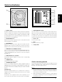
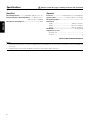
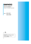
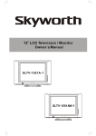
POWERED SUBWOOFER
ENGLISH
SW-26HT
INSTRUCTION MANUAL
KENWOOD CORPORATION
ITALIANO
ESPAÑOL
B61-1154-00 00 MA
(E) KW EW 0111
Before applying power
Caution: Read this page carefully to ensure safe operation.
Units are designed for operation as follows.
ENGLISH
Europe and U.K. ................................................ AC 230V only
Safety precautions
WARNING : TO PREVENT FIRE OR ELECTRIC SHOCK, DO NOT
EXPOSE THIS APPLIANCE TO RAIN OR MOISTURE.
CAUTION
RISK OF ELECTRIC SHOCK
DO NOT OPEN
CAUTION: TO REDUCE THE RISK OF ELECTRIC SHOCK,
DO NOT REMOVE COVER (OR BACK). NO USER-SERVICEABLE PARTS INSIDE. REFER SERVICING TO QUALIFIED SERVICE PERSONNEL.
THE LIGHTNING FLASH WITH ARROWHEAD SYMBOL, WITHIN AN EQUILATERAL TRIANGLE, IS INTENDED TO ALERT THE USER TO THE PRESENCE OF UNINSULATED “DANGEROUS VOLTAGE” WITHIN
THE PRODUCT’S ENCLOSURE THAT MAY BE OF SUFFICIENT MAGNITUDE TO CONSTITUTE A RISK
OF ELECTRIC SHOCK TO PERSONS.
THE EXCLAMATION POINT WITHIN AN EQUILATERAL TRIANGLE IS INTENDED TO ALERT THE USER
TO THE PRESENCE OF IMPORTANT OPERATING AND MAINTENANCE (SERVICING) INSTRUCTIONS
IN THE LITERATURE ACCOMPANYING THE APPLIANCE.
2
Introduction
Thank you for selecting our speakers as part of your high-fidelity system. We at KENWOOD are confident that your choice will bring you
years of rich listening pleasure. Please take the time to read through this booklet carefully. It will help you to obtain the peak performance
for which the speakers were designed.
For your records
Record the serial number, found on the back of the unit, in the spaces designated on the warranty card, and in the space provided below.
SW-26HT Serial number
Unpacking
Unpack the unit carefully and make sure that all accessories are put aside so they will not be lost.
Examine the unit for any possibility of shipping damage. If your unit is damaged or fails to operate, notify your dealer immediately.
If your unit was shipped to you directly, notify the shipping company without delay. Only the consignee (the person or company
receiving the unit) can file a claim against the carrier for shipping damage.
We recommend that you retain the original carton and packing materials for use should you transport or ship the unit in the future.
Keep this manual handy for future reference.
Accessories
Pin-plug cord (1)
Cushion (4)
Contents
Caution: Read the pages marked
carefully to ensure safe operation.
Before applying power ............................................................................................................................................................ 2
Safety precautions .................................................................................................................................................................. 2
Introduction .................................................................................................................................................................................... 3
IMPORTANT SAFEGUARDS ................................................................................................................................................... 4
Installation ...................................................................................................................................................................................... 6
Connections ................................................................................................................................................................................... 6
Controls and indicators .................................................................................................................................................................. 7
Specifications ................................................................................................................................................................................. 8
3
ENGLISH
Refer to these model and serial numbers whenever you call upon your KENWOOD dealer for information or service on this product.
Model SW-26HT is composed of the front speakers, center speaker and rear (surround) speakers.
IMPORTANT SAFEGUARDS
Caution: Read this page carefully to ensure safe operation.
ENGLISH
Please read all of the safety and operating instructions
before operating this appliance. Adhere to all warnings on
the appliance and in the instruction manual. Follow all the
safety and operating instructions. These safety and operating
instructions should be retained for future reference.
1. Power sources – The appliance should be connected to
a power supply only of the type described in the
instruction manual or as marked on the appliance. If you
are not sure of the type of power supply to your home,
consult your appliance dealer or local power company.
For appliances intended to operate from battery power,
or other sources, refer to the instruction manual.
2. Power-cord protection – Power-supply cords should
be routed so that they are not likely to be walked on or
pinched by items placed upon or against them, pay
particular attention to cords at plugs, convenience
receptacles, and the point where they exit from the
appliance.
6. Temperature – The appliance may not function properly
if used at extremely low, or freezing temperatures. The
ideal ambient temperature is above +5°C (41°F).
7. Heat – The appliance should be situated away from heat
sources such as radiators, heat registers, stoves, or
other appliances (including amplifiers) that produce
heat. Do not place a flaming object, such as a candle or
lantern, on or near the appliance.
8. Electric shock – Care should be taken so that objects do
not fall and liquid is not spilled into the enclosure
through openings. If a metal objects, such as a hair pin
or a needle, comes into contact with the inside of this
appliance, a dangerous electric shock may result. For
families with children, never permit children to put
anything, especially metal, inside this appliance.
Never pull or stretch the cord.
3.
CAUTION – Polarization – This appliance may
be equipped with a polarized alternating-current line
plug (a plug having one blade wider than the other). This
plug will fit into the power outlet only one way. This is
a safety feature. If you are unable to insert the plug fully
into the outlet, try reversing the plug. If the plug should
still fail to fit, contact your electrician to replace your
obsolete outlet. Do not defeat the safety purpose of the
polarized plug.
4. Ventilation – Slots and openings in the cabinet are
provided for ventilation and to ensure reliable operation
of the appliance and to protect it from overheating, and
these openings must not be blocked or covered. The
appliance should be situated so that its location or
position does not interfere with its proper ventilation.
To maintain good ventilation, do not put records or a
table-cloth on the appliance. Place the appliance at least
10 cm away from the walls.
Do not use the appliance on a bed, sofa, rug or similar
surface that may block the ventilation openings. This
appliance should not be placed in a built-in installation
such as a bookcase or rack unless proper ventilation is
provided or the manufacturer’s instructions have been
adhered to.
5. Water and moisture – The appliance shall not be
exposed to dripping and splashing - for example, near a
bathtub, washbowl, kitchen sink, laundry tub, in a wet
basement, or near a swimming pool, etc. Do not place
an object containing liquid, such as a flower vase, on the
appliance.
4
9. Enclosure removal – Never remove the enclosure. If
the internal parts are touched accidentally, a serious
electric shock might occur.
10. Magnetic fields – Keep the appliance away from sources
of magnetic fields such as TV sets, speaker systems,
radios, motorized toys or magnetized objects.
11. Cleaning – Unplug this appliance from the wall outlet
before cleaning. Do not use volatile solvents such as
alcohol, paint thinner, gasoline, or benzine, etc. to clean
the cabinet. Use a clean dry cloth.
12. Accessories – Do not place this appliance on an unstable
cart, stand, tripod, bracket, or table. The appliance may
fall, causing serious injury to a child or adult, and serious
damage to the appliance. Use only with a cart, stand,
tripod, bracket, or table recommended by the
manufacturer, or sold with the appliance. Any mounting
of the appliance should follow the manufacturer’s
instructions, and should use a mounting accessory
recommended by the manufacturer. An appliance and
cart combination should be moved with care. Quick
stops, excessive force, and uneven surfaces may cause
the appliance and cart combination to overturn.
Caution: Read this page carefully to ensure safe operation.
13. Lightning – For added protection for this appliance
during a lightning storm, or when it is left unattended
and unused for long periods of time, unplug it from the
wall outlet and disconnect the antenna or cable system.
This will prevent damage to the appliance due to lightning
and power-line surges.
ANTENNA
LEAD IN WIRE
GROUND CLAMPS
ANTENNA
DISCHARGE UNIT
(NEC SECTION 810-20)
ELECTRIC SERVICE
EQUIPMENT
NEC – NATIONAL ELECTRICAL
CODE
15. Damage requiring service – The appliance should
be serviced by qualified service personnel when:
A. The power-supply cord or the plug has been
damaged.
B. Objects have fallen, or liquid has been spilled
into the appliance.
C. The appliance has been exposed to rain or
water.
D. The appliance does not appear to operate
normally by following the instruction manual. Adjust
only those controls that are covered by the instruction
manual as an improper adjustment of other controls
may result in damage and will often require extensive
work by a qualified technician to restore the appliance
to its normal operation.
E. The appliance has been dropped, or the
enclosure damaged.
F. The appliance exhibits a marked change in
performance.
16. Servicing – The user should not attempt to
service the appliance beyond that described in
the instruction manual. All other servicing should
be referred to qualified service personnel.
17. Outdoor antenna grounding – If an outside
antenna is connected to the appliance, be sure
the antenna system is grounded so as to provide
some protection against voltage surges and built
up static charges. Article 810 of the National
Electrical Code
ANSI/NFPA 70, provides
information with respect to proper grounding of
the mast and supporting structure, grounding of
the lead-in wire to an antenna discharge unit, size
of grounding conductors, location of antenna
discharge unit, connection to grounding
electrodes, and requirements for the grounding
electrode. See Figure.
GROUNDING CONDUCTORS
(NEC SECTION 810-21)
GROUND CLAMP
POWER SERVICE GROUNDING
ELECTRODE SYSTEM
(NEC ART 250, PART H)
18. Power lines – An outside antenna system should not
be located in the vicinity of overhead power lines or
other electric light or power circuits, or where it can fall
into such power lines or circuits. When installing an
outside antenna system, extreme care should be taken
to keep from touching such power lines or circuits as
contact with them might be fatal.
19. AC outlets – Do not connect other audio
equipment with a power consumption larger than
that specified to the AC outlet on the rear panel.
Never connect other electrical appliances, such
as an iron or toaster, to it to prevent fire or electric
shock.
20. Overloading – Do not overload wall outlets, extension
cords, or integral convenience receptacles as this can
result in a risk of fire or electric shock.
21. Attachment – Do not use attachments not
recommended by the appliance manufacturer as they
may cause hazards.
22. Replacement parts – When replacement parts are
required, be sure the service technician has used
replacement parts specified by the manufacturer or
have the same characteristics as the original parts.
Unauthorized substitutions may result in fire, electric
shock, or other hazards.
23. Safety check – Upon completion of any service or
repairs to this appliance, ask the service technician to
perform safety checks to determine that the appliance
is in proper operationg condition.
24. Do not mount this appliance to a wall or ceiling. Refer to
the installation section for proper placement.
Notes:
1. Item 3 is not required except for grounded or polarized equipment.
2. Item 17 and 18 are not required except for units provided with antenna terminals.
3. Item 17 complies with UL in the U.S.A.
5
ENGLISH
14. Abnormal smell – If an abnormal smell or smoke
is detected, immediately turn the power OFF and
unplug the appliance from the wall outlet. Contact
your dealer or nearest service center.
EXAMPLE OF ANTENNA GROUNDING AS PER
NATIONAL ELECTRICAL CODE
Installation
The Subwoofer is a virtually omnidirectional speaker, so it can
be installed in almost any location. For example, the Subwoofer
Howling
can be installed next to the component system (consisting of
howling sound may be generated. If this occurs, place the
Subwoofer farther away from the turntable or reduce the
an amplifier, tuner, cassette deck, etc.), or in a corner of the
room, etc.. The subwoofer’s deep-bass reproduction charac-
Subwoofer volume (By rotating the VOLUME control
counterclock-wise). The howling phenomenon may also occur
ally monaural, only one subwoofer is necessary to obtain a
due to cross interference with a cassette deck, compact disc
player, or Laserdisc player, although this is very rare. If sound
sufficient stereo effect when used in combination with a stereo music system.
or picture seems to be distorted due to this reason, place the
Subwoofer farther away from other components or reduce its
volume.
Wall
Near the wall
B
Far from the wall
C
A
Wall
Operation near a TV
If the Subwoofer is installed too close to a TV, color irregulari-
Near the corner
ties may be observed on the TV screen. If such irregularities
occur, switch the power of the TV to OFF and then switch it
ON again after waiting for a period of 15 to 30 minutes. The
influence of the Subwoofer on the TV picture may be improved
by self-demagnetization of the TV set. If the color irregularities
still persist, move the Subwoofer farther away from the TV.
Speaker installation position, viewed from above
Caution
A
Sound Pressure Level
ENGLISH
teristics are richest when the subwoofer is installed in a corner
or near a wall. Since the low-bass component in music is usu-
If the Subwoofer is installed near an analog record turntable, a
Near the corner
B
Near the wall
C
Far from the wall
Frequency
To assure ventilation, observe the follow- Vertical installation
ing points when installing the unit.
• Leave a distance of more than 10
cm between the heat sink of the
Subwoofer and the surrounding
wall(s).
Use special care not to cover the
heat sink with a curtain, etc. when
installing.
•
Be sure to install the Subwoofer vertically.
Connections
Before connection:
Set the POWER switches of the amplifier and Subwoofer to OFF. If they are connected with the POWER switch(es) left
ON, one or both components may be damaged.
SW-26HT SUBWOOFER
SUBWOOFER
PRE OUT
SUBWOOFER
PREOUT
Pin-plug cord
Amplifier or Receiver
6
Controls and indicators
-
ENGLISH
1
3
2
5
4
8
7
6
0
9
1 PHASE switch
The phase relation between the subwoofer and front speakers
varies according to the distances, and the subwoofers setup
location. Set the phase switch to NOR. (normal phase) or REV
(reversed phase) so as to get the best bass sound at the location at which you normally listen.
8 AUTO SHUTOFF switch
Use this switch to set the automatic shutoff feature ON or
2 CROSSOVER knob
Adjust as necessary for optimal volume of the subwoofer and
frequency balance of speakers.
9 Power cord
Connect to AC outlet.
3 VOLUME knob
Adjusts the volume level of the output of the Subwoofer. Rotating the knob clockwise increases the volume level, and ro-
OFF. If you set this ON, the subwoofer will automatically enter
standby mode if it does not receive a signal from the receiver
for a period of 30 minutes. The subwoofer will automatically
resume normal power when output from the receiver resumes.
0 Duct
Extend low-frequency output.
- Loudspeaker
tating the knob counterclockwise decreases the volume level.
4 LINE INPUT (R, L/MONO) terminal
Use to connect to the corresponding SUBWOOFER PRE OUT
jacks on your receiver. If your receiver has only one
SUBWOOFER PRE OUT jack, make the connection using the
L/MONO jack.
5 LINE OUTPUT (R, L) terminal
These jacks relay the signals received at the corresponding
LINE INPUT jacks.
6 POWER switch
Switches the power ON and OFF.
7 STANDBY/ON indicator
Comes on to indicate that power is being supplied. Lights up
GREEN during normal operation; lights up RED if the subwoofer
has been switched into standby mode by the AUTO SHUTOFF
feature.
Standby mode
While the standby indicator is lit, a small amount of power is
supplied to the system to back up the memory. This is called
standby mode.
The power in this equipment will not be completely cut off
from the AC wall outlet when the main switch is turned OFF.
Caution concerning operation
An excessive input level to the Subwoofer may impair the sound
quality or damage the unit. Careful attention should therefore
be paid to the following precautions.
Notes:
1. Do not increase the output of the amplifier to a high level
while the low-frequency level is enhanced by the amplifier’s
tone control or loudness control.
2. When operating the amplifier switches or when placing
the stylus on an analog record, set the amplifier volume to
its minimum level.
7
Specifications
Caution: Read this page carefully to ensure safe operation.
Type ...................... Subwoofer system with built-in amplifier
[Speaker]
Rated Output Power ........... 50 W RMS (100 Hz, 0.1%, 4Ω)
Enclosure .......................... Bass-Reflex, Floor Standing Type
Input Sensitivity & Input Impedance ........ 100 mV / 43 kΩ
200 mV / 43 kΩ (MONO)
Speaker Units ........................... 160 mm (6-1/2 ") Cone type
Nominal Impedance ....................................................... 4 Ω
Rated Power Consumption ........................................ 50 W
Dimensions
Width ............................................... : 290 mm (11-7/16 ")
ENGLISH
[Amplifier]
Height ............................................. : 300 mm (11-13/16 ")
Depth ............................................... : 420 mm (16-9/16 ")
Net Weight ...................................................... 10 kg (22.0 lb)
Supplied accessories
Pin-plug cord .................................................................. 1
Cushion .......................................................................... 4
NOTE: DO NOT REMOVE THE GRILLE.
Notes:
1.
Kenwood follows a policy of continuous advancements in development. For this reason, specifications may be changed without notice.
2. Full performance may not be exhibited in extremely cold locations (below 0 deg. C).
8