1
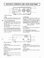
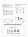
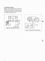
FEATURES
The Model AT-130 is designed to satisfy your
antenna-tuning requirements. It has been manufactured with the quality and performance that
makes Kenwood "The Pacesetter in Amateur
Radio".
This unit has been carefully engineered and manufactured under rigid quality standards, and should
give you satisfactory and dependable operation
for many years.
Should any trouble arise with this unit, please
contact the authorized KENWOOD dealer from
whom you purchased the item.
AFTER UNPACKING
Shipping Container: Save the boxes and packing
in the event your unit needs to be transported
for remote operation, maihtenance, or service.
The following explicit definitions apply in this
manual.
NOTE:
If disregarded, inconvenience only.
No risk of equipment damage or personal injury.
CAUTION: Equipment damage may occur, but
not personal injury.
1. The AT-130 is a high performance H F antenna
tuner and is a modification of the popular
AT-200 antenna tuner. The AT-130 is sma!l
and light, and is suitable not only for operation in your HAM shack but also for mobile
or field operation.
2. The AT-130 consists of an antenna coupler, an
SWR meter, and an antenna switch.
3. The AT-130 is designed to be used on the
Amateur bands between 3.5 MHz and 30 MHz.
4. Antenna MATCHING or THROUGH operation is BAND-switch selected.
5. The SWR meter operates in both THROUGH
and MATCHING modes.
6. A mounting bracket is included for mobile
operation.
7. The panel meter can be illuminated by an
external power source.
8. The antenna matching circuit is also effective
in reducing TVI since it acts as a band-pass
CONTENTS
AT-130 Specificat ions . . . . . . . . . . . . . . . . 3
Section 1. Preparation for Use . . . . . . . . . . 4
Section 2. Controls and their functions . . . . 5
Section 3. Operation . . . . . . . . . . . . . . . .6
Section 4. Circuit Description . . . . . . . . . . 9
Section 5. Additional Information
. . . . . 10
Schematic Diagram . . . . . . . . . . . . . . . . . 1 1
w
(,,PIL-~) w w 691
-a
(1,9) wwz91
'M
(,,8/&-Z) ww09
'H
pnls pue lnu 6 u ! ~
( ~ 0 )adAl
4
dHfl
(U09)adAljHfl
.y3$ew wnw!ldo
l e g p 5.0 ueyl ssa1
( M OZ 1 'Pueq
ZH W 4'&) 'Xew M 0s 1
'pa3uelequn ' uoo& 01 02
004
ZH W L'6Z 01 S'E
w o spueq
~ ~ ~na~ewe.8
Accessories:
Carefully unpack your AT-130 Antenna Tuner
and verify the following accessories are included.
* Operating manual
. .
1 copy
* Mounting bracket (J29-0402-02)
1 piece
* Mounting hardware
Screw, 4 mm diameter .
4 pieces
Flat washer, 4 mm diameter .
4 pieces
Lock washer, 4 mm diameter . 4 pieces
Nut, 4 mm diameter . .
. 4 pieces
Wing Bolt, 4 mm diameter
(~09-0007-05) . . 4 pieces
4 pieces
. .
Polyethylene washer
* 2P power plug (~09-0203-25). . .
1 piece
* Ground lug (~23-0015-04).. . . 1 piece
.. .. ...
..
. .. ...
. .
.
... .
.
. .. ..
.
..
Interconnection Cable
To connect your AT-130 with the TS-130S(V).
or other transceiver, an interconnection cable is
required.
Refer to Figure1-1 for details.
-
Meter Lamp Power (Figure 1-21
Power for the meter lamp i s supplied from an
external power source. Use the supplied 2 PIN
plug for power-supply connection. Observe polarity.
Cut end of cable even. Using a sharp
knife or razor, score and remove the
sheath - Don't cut the braid.
I
Slide the coupling over the cable, and
carefully solder the connector. Make
certain the insulation is not melted by
Figure 1-2. Meter Light Power Connection
1
!- SECTION 2. CONTROLS AND THEIR FUNCTIONS
-I
JIIIII~~IIIII~~~~~~I~~IIIII~~IIIII~~IIII~~~IIIII~~IIIII~~IIIII~~IIIII~~IIIII~~IIIII~~IIII~~~IIIII*~IIIII~IIIIII~~IIIII-~
~~~~~~~~~~~~~~~~~~~I~-~IIII~.~IIII~~~IIII~.~~III~.~IIII~~~IIII~.~IIII~.~IIII~.~IIII~.~II~I~.~IIII~.
PULL LAMP
rI
71
ANTENNA TUNER AT- 130
r
71
Figure 2-1 Front view
1. Meter
The meter reads SWR (standing-wave ratio) and
may be illuminated by an external power source.
2. CAL (Calibrate)/SWR Switch
To measure SWR, first set this switch to the
)
Adjust the CAL control until
CAL (1position.
the meter pointer swings to the CAL line on
the meter scale.
position,
Then depress the switch to the SWR (1)
and read the SWR.
3. CAL (Calibrate) ControlIMeter Lamp Switch
Before measuring SWR, this control is used to
calibrate the meter. Adjust as described above
in item 2. The meter lamp lights when the
control is pulled ON.
4. BAND Switch
Set this switch to the band in which you are
operating. The BAND switch also has a
"THROUGH" position at which the antenna i s
connected directly to the transceiver. SWR can
also be measured a t the THROUGH position.
CAUTION: DO NOT operate the band switch
while
transmitting.
Equipment
damage WI L L occur.
5. R TUNE
The R TUNE adjusts the resistive component of
antenna impedance.
6. X TUNE (~ransmit~ u n i nControl
~)
The X TUNE adjusts the reactive component of
antenna impedance.
Figure 2-2. Rear View
1. Serial No. Plate
This plate is stamped with the Serial Number of
your unit.
2. GND post
Connect the GND post to the transceiver GND
stud. Use as short a cable as possible, using the
supplied ground lug.
3. 12V DC
Accepts 12V DC for meter illumination. Use the
supplied plug.
NOTE: Viewed from the rear, the right terminal
is POSITIVE.
4. INPUT Connector
The INPUT UHF connector accepts the H F input
signal fed from the antenna connector on the
transceiver.
5. ANT Connector
The ANT UHF connector accepts the antenna
coaxial cable.
b
Measuring antenna system SWR
(i) Using an all solid-state transceiver (such as a
TS-130s or TS-130V)
Before setting up the antenna coupler, first
determine the antenna system SWR.
a. Set the controls as shown in Figure3-2. Set the
BAND switch to the "THROUGH" position.
b. In the transmit mode, calibrate the meter with
the calibration control.
c. Depress the CALISWR switch to the SWR (1)
position and read SWR. If the SWR is lower
than 1.5: 1 the antenna system impedance
i s sufficiently matched for practical use. If
above 1.5: 1, tune the system.
NOTE: In the event of too high an SWR (over
10: I),
check the antenna system for
breaks or a short circuit.
(ii)Using a tube power amplifier transceiver (such
as a TS-820)
Connect the transceiver (or transmitter) and
dummy load (or antenna) through the AT-130 as
shown in Figure 3-3. Before adjusting the antenna
coupler, you should first know the antenna system SWR.
Connect the dummy load to the ANT connector
and adjust the transceiver (or transmitter) final
tuning. Then, replace the dummy load with the
antenna and measure the antenna-systemSWR.
NOTE: During antenna measurements, your
transceiver may be operating under
heavy loading conditions.
Your signal may also interfere with
other stations. Use the least amount of
power possible, and complete measurements as quickly as possible.
e
l
Coax.
T
,
\
Ground lead
Figure 3-1. Interconnection
I:
BAND
R TUNE
CAL
@
PULL LAMP
k
ANTENNA
1
1
Switch out set
CAL (
control
Figure 3-2. Switch Settings
6
Table 3-1 shows approximate control positions
for coupler adjustment.
Adjusting the Antenna Coupler
The antenna coupler is used to match a transmitter to an antenna system when i t s SWR is too
high (i.e., greater than 1.5:1 SWR).
a. Place the BAND switch to the same band
setting as your transceiver (as shown in Figure
3-41,
b. Set the CALISWR switch to the CAL ( I )
position.
c. Transmit and adjust the CAL control so the
meter indicates CAL.
d. Place the CALISWR switch in the SWR) , (
position.
e. Ncw you will measure the reflected power.
Adjust the R TUNE and X TUNE controls
alternately for a good minimum meter indication. Reflected power will be close to zero as
a good match is achieved.
Table 3-1
I
BAND(MHz1
I
I
R TUNE
I
X TUNE
-
-
-p
-
B. A N T System
A. D u m m y load
TS-820 o r other Transceiver
--f
1
I
Ii
I I
I19 M
.-
I
.-a
A T - 120
0 0 0
oo!l
oooll
II!
-
~.-
ANT
1
4-
-
-
-
1l
First tune u p o n
A D u m m y load.
Then check
antenna SWR.
_
..
necessary.
r71
-
--
Coax.
INPUT
Coax.
G r o u n d Cable
Figure 3-3. Inter Connection
-Adjust alternately f o r m i n i m u m
SWR reading.
4
R TUNE
BAND
PULL LAMP
c
.~
@
X TUNE
ANTENNA TUNER AT- 130
Figure 3-4.
.',
.
.-
AT-130 Mobile Installation
.
Securely install the Mobile Mount using four lock
washers, four flat washers, and four screws and
nuts. Install the AT-130 in the Mobile Mount by
four wing bolts and polyethylene washers. Adjust
the tilt before tightening the bolts.
Mounting bracket
Figure 3-5. Mounting bracket Detail
Figure 3-6. Adjusting the Mounting Angle
Figure 11 shows a block diagram of the AT-130.
Direcltional Coupler
The directional coupler samples forward and
reflected power from the transceiver to the load.
Meter Circuit
The forward and reflected power sampled by the
directional coupler is used for SWR measurement. Forward power i s calibrated with the CAL
control so reflected power is read as SWR.
Band Selector Switch
This selects the band to which the matching
circuit is tuned. In the "THROUGH" position,
Idthe
antenna i s connected directly to the trans- ceiver, bypassing the coupler, while s t i l l allowing
SWR measurement.
Antenna Coupler
The universal matching circuit is capable of
matching 20 t o 300n loads to the 50a input
impedance.
1
INPUT DIRECTIONAL
COUPLER
-c
BAND
SELEC---c
TOR
ANTENNA
COUPLER
I
METER
CIRCUIT
@
ANT
n
GND
Figure 4-1. AT-130 Block Diagram
i
1. General lnformation
Your AT-130 has been factory aligned and tested
to specification before shipment. Under normal
circumstances, it wili operate in accordance with
these operating instructions.
If your unit fails to work, contact the authorized
dealer from which you purchased it for quick,
reliable repair.
Attempting service without factory authorization
can void the unit's warranty.
2. Ordering Spare Parts
When ordering replacement or spare parts for
your equipment, be sure to specify the following:
Model and serial number of your transceiver,
Schematic number of the part. Printed circuit
3. Service
You may return your unit for service either t o
the Authorized Kenwood Dealer from whom you
purchased it or to Trio-Kenwood. A copy of the
service report will be returned with the unit.
Please do not send sub-assemblies or printed
circuit boards-send the complete unit, in i t s
original boxes and packing.
You need not return accessory items unless they
are directly related t o the service problem.
I f you want verification of receipt, please supply
a self-addressed card (or letter) and we will
inform you of the date of receipt and estimated
service time.
NOTE: When claiming warranty service, please
include a photocopy of the bill of sale,
or other proof of purchase showing the
date of sale.
Dear OM, if you desire to correspond on
a technical or operational problem,
please make your note short, complete,
and t o the point. And PLEASE make
it readable.
Please list: Model and serial number.
The question or problem you are
having.
Please give sufficient detail t o diagnose; other
equipment in the station, meter readings and
anything you feel might be useful in attempting
diagnosis.
T
-
w
4. Dial Lite lnformation
B30-9996-00
Part #
Rating
12V 40mA
To replace:
1. Remove top cover.
2. Note position of all leads on S meter and
lamp P.C.B.
3. Remove all leads from meter and lamp
P.C.B.
4. Remove meter bracket.
5. Remove 2 brass Philips screws holding
lamp P.C.B. to meter.
6. Swing P.C.B. rear edge up and out.
8. Reverse disassembly procedure.
c
1
Circuits and specifications are subject to change for improvement.
~
[gcT
SWR
LAMP 12V
Model :
Serial
AT-130
.........................................................................................................
Date Purchased.....................................................
Dealer
...........................
........................................................................................................
A product of
TRIO-KENWOOD CORPORATION
1715. 2-chorne. s h l b u y a . sh~buya-KU
Tokyo 150. Japan
TRIO-KENWOOO COMMUNlCAllONS
11 1 ) West Walnut Street Cornoton Calfornra 9 0 2 2 0 U S A
TRIO-KENWOOO COMMUNICATIONS. GmbH
D 6 3 7 4 Stelnbach TS lndustr~estrasse8 A West Germany
TRIO-KENWOOD ELECTRONICS, N.V.
Leuvensesteenweg 5 0 4 8 1 9 3 0 Zaventem B e l g ~ u m
TRIO-KENWOOD [AUSTRALIA) PTY. LTD.
4 E Woodcock Place Lane Cove N S W 2066 Australla
0 2 5 3 0 9 P R I N T E D I N JAPAN 850-3928-08 (K.0)