1
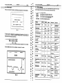
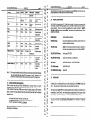
.~
DAIO
177
~.
GR-526/510
Vehicle Radiation
S0~a-e
Monitor
Version - 2V16
OPERATORS MANUAL - Rev 2.2
Table of Contents
GR-526/510
1.0
1.1
Vehicle Monitoring
1.2
System
1.3
i.4
OPERATORS MANUAL
(PART NO. 93516-3)
REV 2.2
Sa¶wm
msti ml6
2.0
2.1
2.2
2.3
2.4
2.5
2.6
2.7
2.8
2.9
2.10
GENERAL .........................................................................................................
...... ..............................................
INTRODUCI-ION.. ...........................................
GR-526/510 SYSTEM DESCRIPTION (General). .....................................................
IN CASE OF DIFFICULTY ...........................................
..........................................
DOCUMENTAnON .............................................................................................
*
2
2
3
,4
OPERATION
...5
.................................................................................................
GR-526/510 CONSOLE PRIMARY FEATURES ........................................................
5
POWER SWlTCH ....................................................
............................................ 5
Z+RTUP SCREEN .................................
............................................................. 6
DISPLAYMESSAGES .......................................
7
....................................................
....................................................................
ERRORS DURING INïl-IALIZATION..
8
TRAFFK LIGHT SYSTEM.. ...................................................................................
9
SPEED ALERT.. ..........................................
9
............... .,.........................................
CURRENT PARAMEIERS - PRINTOUT ........................................... ..................... 10
SYSIEMTEST......................................... ..... .....................................................
10
TELE-CHECK ..............................................
...................................................... 11
3.0 ALARM DISPLAYS AND PROCEDURES .............................................................. ..12
3.1
IF AN AIARM OCCURS.. ...................................
...... ........................................... 12
3.2
DANGER (LEVEL 5) ALARM ..............................................
. ...... ......................... 12
3.3 ALARM TIMING ...........................................
...................................................... 13
3.4
ALARM LNELS - detaikd explanation .............................................................. 14
3.5
ALARM LEVELS AND EXPOSURE LIMiTS ............ . ...............................................
14
3.6 ALARM PROCEDURES.. ......................................................................................
15
4.0
VIEWING
ALARM DATA IN MEMORY
5.0 PARAMETER
................................................................
SETTINGS .....................................................................................
17
18
*
tw I.?’
Or-~l~::l!Q
1
arm
SYSTEM PASSWORDS
. . . . . . . .. . . . . . .. . . . . . . . . . . . . . . . . . . . , . . . . . . . . . . . .. . . . . . . .
APPENDIX
K - RECOMMENDED,MAINTEtiANCE
PROCEDURES
APPENDIX
N - SYSTEM TESTING ..* . .. .. . . . .. . . .. . . .. . . . . .. . . . .. .. . . . .. . . . .. .. .. .. .. .. . . . .. . . . . .. .. .. . . . . . . . . . . 25
.. .. . . . . . . . . . . .. . . . . . . . . . . . . . . . . 23
1..,. l -*a
‘cj
G..l
éXPLORANIUM
,a
GR-5261510
OPERATORS MANUAL
for
DYNAMIC VEHICLE RADIATION
Sohme
G:a
MONITORING
Version - 2V16
USERS ARE HEREBY NOTIFIED THAT THIS MANUAL CONTAINS
TECHNICAL INFORMATION OF A PROPRIETARY NATURE. THIS
INFORMATION
IS
NECESSARY
FOR
TECHNICALLY
KNOWLEDGEABLE USERS TO UNDERSTAND SYSTEM OPERATION
AND TO SATISFY THEMSELVES THAT THE SYSTEM IS
PERFORMING CORRECTLY.
EXPLORANIUM ACCEPTS THAT IT IS THE RIGHT OF SUCH USERS
TO BE PRIVY TO THIS INFORMATION.
HOWEVER THIS
DOCUMENTATION IS PROVIDED SOLELY FOR THE BENEFIT OF
OWNERS OFTHE GR-500 SERIES SYSTEM AND DISSEMINATION
OF THE DETAILED TECHNICAL INFORMATION PROVIDED MAY
BE CONSIDERED AS LEGALLY CONTRAVENING THE NORMAL
SUPPLIER/CUSTOMER RELATIONSHIP.
UNAUTHORIZED
RELEASE
OF
DETAILED
TECHNICAL
IN,FORMATION TO A THIRD PARTY WILL BE CONSIDERED AS A
CONTRAVENTION OF USER AGREEMENTS.
1.1 INTRODUCTION
The GR-500 Series are the state-of-the-art
radiation monitoring systems for Truck/Rail
vehicles in the scrap metal processing and recycling industries. The GR-500 Series has been
specifically designecl to detect the presence of potentially shielded or un-shielded radioactive
sources that are buried in scrap metal.
TO prevent these expensive, and,potentially dangerous accidents, EXPLORANIUMdeveloped the
GR-520 Radiatioh Detecticn System in 1988, which was the hrst system capable of detecting
BURIED shielded sources; Current mcclels include the high-sensitivity GR-510 and GR-526 systems,
and the recently introduced AT-900 system. Exploranium has installed over 500 radiation detection
systems in steel mills and scrap handling facilities in 17 countries lncluding USA, ‘Canada, Mexico,
Germany, Sweden, Finland, Italy, Denmark, UK, Ireland and many muntries in Asia.
It is impossible
for ANY system to catch ALL potential
incoming sources for a
variety of technical reasons (see Appendix A). However the technology
built into
the GR-526/5X0
together with our previous experience PLUS some recent major
limit in this
technical
breakthroughs,
make the GR-526/510 THE technical
specialised
monitoring
technology.
The GR-526/51g
wi!! detect almost aii
potential “normal”
sources that cari be expected to be in the scrap stream and
compensate
for most logistic limitations
commonly
seen in scrap hand%
facllitles.
The GR-526/510 offers the highest level of sensitivity, case of use and system reliability of any
scrap metal radiation monitor, through the following features:
- Very large Polyvinyl toluene (PVT) “plastic” detectors.
- Easy user interface via the large Graphies display plus printer output.
- One-button Alarm response for the user
- Continuous automatic system self-diagnosis with user notification
- Redundancy of key system components.
- Tele-Check with full performance data analysis/service support via built-in modem.
- Extensive Exploranium Service Centre support for customer questions.
- FREE software updates to continuously improve performance
1.2 GR-526/510 SYSTEM DESCRIPTION (General)
The GR-5261510 Radiation Detection System ccnsists of a system consale and two detector boxes
(maximum = 8 detector boxes for special applications). lhe detectors are usually mounted at the
entrante to a truck or rail scale. The system console cari be mounted In the scale house or any
other convenient indoor monitoring location.
Radioactive sources, both naturally occurring and man-made, emit Gamma-rays that are absorbed
by the detectors and pmduce scintillations, small flashes of light, which are converted to pulses in
the detector electronics. The system console coilects and monitors the Gamma-ray information from
the detebors and displays the data on the front pane1 Liquid Crystal Display (Console Display) in a
“chart recorder” format.
c
”
GR-526510 OPERATORSManua,
WEb
2”16
page:3
If~system
ad
oelalled alarm lmormatlon is displayed on the Console Display.
z.2
c”
c
The GR-526/510 also performs contlnuous system diagnosis. If a component failure is detected,
signal5 cari be re-routed to take advantage of back-up systems designed into the GR-526/510. Any
system faults that are detected, are displayed on the Console Display enabling Maintenance to be
scheduled. The GR-526/510 Will continue to operate even if some maior comwnents bave failed,
to give the user the MAXIMUM detection capability during this period.
The GR-526/510 system has been specially designed for ONE-BUTTON. The system is designed to
monitor all interna1 components and to automatically alert the user to any system malfunctions.
ADVANCED
SYSTEM DESIGN PERMITS
THE SYSTEM TO OPERATE
PERFORMANCE LEVELS WllHOUT
REOUIRING THE SCALE OPERATORTO
UNTIL AN ALARM OCCURS.
AT MAXIMUM
,,OANV,‘,,ING
.c
Various support documentation is available for the GR-5261510 system:
‘2
1) SYSTEM SUMMARY
CARD - a 1 page (2 sided) laminated tard that summarizes system
operation, supplied ~41thall systems. Part #93512
2) GR-500
In the event of a problem, customers cari contact the Ewploranium Service Centre closest to them
6108 Edwards
Blvd.,
Telephone
: (9Okq670-7071
Fax
: (905)670-7072
Pager
(416)
:
2) Exploranium-Europe-
Mississauga,
Dan Hoover
Fred Walker
John Crook
ENVI-2000
1 A, Brno 638 00, Crech Republic
:
Vaclucova
Telephone
:
[033](420)5-45-22-2020
Fax
:
[033](420)5-45-22-2024
Mobile
:
[033](420)602-702-075
personnel
ON LST 2V7, Canada
614-4551
Address
Setvice
SERIES OPERATORS
MANUAL
- part
#93516-3
This manual covers basic system operatlon, alarm information, alarm responses, basic system
maintenance and basic errer analysis of system performance.
3) GR-500
SERIES SYSTEM MANUAL
- part
#93516
Tbis is an In depth manual that covers system setup, parameter selection as well as normal
system use.
SERIES MAINTENANCE
MANUAL
- part #93509
Tbis is a detailed manual specially for Maintenance User~ may request a special Maintenance
Manual for more In depth det& of system operation primarily for maintenance personnel.
1.3 IN CASE OF DIFFICULN
personnel
p3q.s: 4
1.4 DOCUMENTATION
4) GR-500
Service
vers/wr
2Vlb
GR-526/510 OPERATORSManual
: Ivan Kasparec
lara
Matejek
Thls sectlon summarizes how the system works and glves some details of special operational
parameters that may be selected during system setup. For a full description of each parameter refer to Section 6.
For easy reference sec the laminated 1 page (2 sides) SYSTEM SUMMARY
2.1
GR-526/510
CONSOLE
PRIMARY
CARD.
FEATURES
Primary features are:
Bright graphies Console Display for the display of messages, alarms etc.
RED push-button marked ALARM - used during a Radiation alarm
YEUOW push-button marked STATUS - used for other user functions
Interna1 AUDIO buner referred to as AUDIO
BUZZER
CLEAR, ENTER, RUN, STOP - special function keys used in Maintenance and System Set-Up and a 10 key numeric keyboard - 0 - 9
2 ARROW
keys - for parameter selection
Interna1 PRINTER
for hard copy of alarms (external Printer support if required)
Interna1 MODEM for Remote,,Maintenance access by telephone line
Special output for control of extemal TRAFFIC LIGHTS
Special data output (RS-232) permitting extemal data processing
Note that the system ca” be operated by ANY user by using ONLY THE RED BUTTON,
other buttons are primarily for changing system parameters.
2.2
as the
POWER SWlTCH
The YELLOW power switch is located &i& the system console and cari be reached from the lower
right-hand access dwr. Access to the power switch has deliberately been made difficult to
minimize the chance of unauthorized personnel interfering with system operation.
i
GR-526/510 OPERATORS Mamal
vesti
2V16
Pwe:K
C9
GR-526/510 OFERATORSManuaI
-_
2.4
I
When power to the system is tumed on, the following screen appears on the Console Display:
l
The following message Will be printed on the printer
pp3qeL--~--
M==LS
STANS
TRAFFIC
Audio
User action
Comment5
SYSTEM WARMUP WAIT
Flash
YELLOW
NO”e
None
10 second walt on
system startup
SYSTEM READY
ON
GREEN
None
Nom
Ready to monitor
MHICLE
ON
YELLOW
None
None
Vehicle passing
TELE-MAINTENANCE
ON
GREEN
None
None
Modem access
occuning
3.7 MPH (or Kmlh)
ON
VËilüüS
NO”e
NOne
speed Of the w?hide
3.7,5.2MPH
ON
VàrIOUS
None
None
Vehicle speed IN
and OUT
SPEED ERR
Slow Flash
YELLOW
flash
Slow beep
Press STATUS
Super hlgh speed
vehkk
SPSpd
ON
varlous
None
NO”Z?
Speclal
OS1 ERR
Fast Flash
Various
Fast beep
Cal1
maintenance
Optical Sensor
defective
OSl,Z ERR
Fast Flash
Variws
Fast beep
Cal1
maintenance
BOTH OS defective
OS3,4 ERR
Fast Flash
Various
Fast beep
Cal1
Maintenance
053, 4 defective (if
used)
D&xtor
Fast Flash
Varlous
Fast beep
Cal1
Maintenance
A detector Is
defectlve
COMM FAILURE A
Fast Flash
Various
Fastbeep
Call
Maintenance
Detector A Comm
problem
COMM ERROR A
Fast Flash
Varlous
Fastbeep
Cal1
Maintenance
Detector A Comm
problem
SYSIEM INOPERABLE
Fast Flash
RED
ON sec
Note X1
Stop vehicles
ca11
Maintenance
All detectors are
defective - NO
monltorlng possible
??SACKGROUND
UPDATE??
Fast flash
YELLOW
flash
Fasl beep
Remove
vehlcle and
Excess traffic
IN
analysis (See Appendix F for more details)
are displayed - sec Section 2.4 for details.
(or OS2 ERR)
HH:MM:SS
2VlS
TfiëCONSOLE
DISPLAY is used to alert the user to any problem with the system and to display
system messages advislng the user of the cuvent status of system performance,
(or Km/h)
- 14:23:00 -
(date)
(tlme)
XX represents a diagnostic code for performance
If any faults ARE detected, the ewrs
--
v.m
MESSAGES
1” the table belnw all messages are llsted _
STANS shows the status of the STATUS (Yellow) button
TRAFFIC shows the status of the Traffic Light output (if used)
Audio shows the action of the interna1 audio buzzer
User action - shows the recommended user actions
This startup screen is displayed for a few seconds while all components of the system are
automatically tested. If all parts of the system are working correctly, the Console Display Will
change ta show the Monitoring Display (Fig 2).
RESXX - 02/14/96
G”
DISPLAY
SPEED
MM9D:Y-Y
STATUS
10000
INFORMATION MESSAGES
4201
INFO
ERR Al, cnb
123
SPECIAL MESSAGES
Figure 2
mode
.
GR-526/510 OPERATORSManua,
velsb
GR-526/X0 OPERAï-‘7R5 Manual
IV16
\Y
I
) STANS
TRAFFIC
Audio
User action
--
Comments
w9e : 9
versMn 2V16
The Audio Buuer “auick-beeo” cari onk be stoooed bv oressina STATUS, at which time the user
accepts responsibilib For enshring that’all err& are c&ected.~
) pass again
2.6
TRAFFIC
LIGHT
SYSTEM
Tbe GR-526/510.is supplied with a TLC (TrafFic Light Controller). Exploranium recommends that
users install a complete Traffic Light system as it is very helpful In advislng “sers end drivers of
system operation. There are 4 control lines available and are usually connected to : GREEN,
YELLOW and RE0 lights and an extemal HORN. The Following is the detailed explanation oftheir
cperation and meaning.
system operational, proceed
GREEN steady
GREEN Flashing
both primai-y Optical Sensors are defective, system still alive but
sensitivity significantly reduced.
-
YELLOW
steady
MER - vehicle is being monitored a$ it passes -m system is
not ready (user accessing alarms etc) SOvehicle must WAIT
YELLOW
SLOW F:a§hing
Vehlcle speed Ïûû iiiGti
YELLOW
FAST Flashing
Modem Il0 ermr
System enors (bad OS, or bad detectors)
-
RADIATION ALARM 9
RED steady
EXT. HORN eteady
RADIATION ALARM
-
EXT. HORN SLOW pulsing
Note 1:
2.5
In this unusual condition the Audio is ON and may net be reset using the SATUS button.
The User should switch the system OFF to prevent the audio. Maintenance may
disconnect the audio temporarily while awaiting modem support from Exploranium.
ERRORS OURING
INITIALKATION
When the system goes through SYSTEM INlTlALIZAlION, a thorough check of all system
parameters is made. When these tests are being carried out the screen shown in Fig. 1 is shown.
At the conclusion of these tests, if NO erron are found the display changes to the Monitoring
display. However if the tests determine that errors exists during these tests then the Following
sequence occurs:
-
-
the console Audio Buzzer “fa+beeps” at a 3/sec rate
the STATUS button flashes at a ~/XC rate + Yellow TrafF~cLight
the errors are listed on the display for 10 seconds
AFter 10 seconds the display automatically gces into the Monitoring Mode (sec Fig.2) and the etrors
are displayed - as listed above.
2.7
- SYSIEM INOPERABLE
-
&ed
Alert
SPEED ALERT
TO prevent system sensitivity reductlons caused by excessive vehicle speed, the system has a builtin SPEEDcontrol. The vehicle speed is shown on the Console Display in the “SPEEO” location (sec
Fig. 2). Tbe speed units of measure (mph, Km/h) are selected during Start-Up.
The maximum permissible SPEED of a vehicle passing through tbe detectors is selectable and is
normally set to 3 mph (5 Km/h). Any vehicle passing at a speed above this limit causes a Speed
Alert which gives an Audio alert (beeps) as well as Visuai (YELLOW T&ic light flashes).
The user should realize that reducing
Km/h)
40%
to a maximum
the vehicle speed
of 3 mph (5 Km/h) - effactively
from a maximum
increases system
of 6 mph
sensitivity
(10
by
The Exploranium Service Department computer cari access the system on a regular basis to perform
system performance analysis as required without interfering with system performance. In previous
versions this access interrupted system monitoring SOfrequent contact was required to select a
“quiet” time for data access - but this is not a problem now.
Enter Password C9 - 9 - 9 - 9 - ENTER> to give a printout of current system parameters as
shown in Fig. 3.
CURRENT
4126197
c=30
O=N
ERR=O
D=4
S=D
PlIfi
PARAMETERS
#3214
12:34:19
B=2
N=5
V=lO
1=302=15
3=9 MODrZ
Exploranium offers optional extensive data analysis of system performance with weekly access and
monthly data reports - contact Exploranium for more information and sec Appendix M.
0 0 0
Ver: 2.16.8
O=7
D=N
C=l
L=3
U=U
04/12/97
13:49:15
Figure 3
#3214 - is the Serial Number of the system
Date/Time - is the DateQme of tnp
SL--r-+-,‘*
p”“,““,
The following is a list of the parameter settings:
c=30Background Correction parameter - set to 30
B=2 Background Parameter - set to 2
N=5Number parameter - set to 5
V=lOVehicle Parameter- set to 10
O-NAlarms ONLY by OS - set to NO
1=30LOW Alarm Ll - set to 30 - SOfor GR-510
2=15LOW Alarm L2 - set to 15
3=9HI - Alarm L3 - set to 9 - 4 for GR-510
MOD=2
Alarm Mode parameter - set to 2
ERR-000
Errer Code (= current errer messages sec 6.8 below)
Var:2.16.8 Software Version (dirplay shows 16.8)
D=4 # of detectors - set to 4
0=7
#ofOS-setto7
D=NDust Parameter - set to NO
C=lDiscriminators = 1 = Normal mode = C mode + set at 10
S=DSpeed Alert - set to D (Default)
L=3 Speed Limit - set to 3
ucuSpeed Units + Date Format - U = US Data + mph
(E = Euro date + Km/h, X = US Date +.Km/h, Y = Eure Date + mph)
POff
Datel’Dme of last time system power was switched OFF
G
6
,u
2.9
SYSTEM TEST
In order to help the user test the system on a regular basis special test capabilities are built into the
GR-526/510. Refer to Appendix N for full details.
G
G
b
3.0 ALARM
3.1
DISPLAYS
AND PROCEDURES
IF AN ALARM OCCURS
If a RADIATION
ALARM occws, the
Audio gives a loud,continuous tome and the
display changes to show the alarm (Fig 4)
and the alarm is automatically printed (Fig
5) (unless this option is disabled). The
14udio alarm Will continue indefinitelv until
the red ALARM button is pressed.
,
----------
-A
--------------
Figure 4
In the Alarm Display (Flg 4) variws data are displayed:
ALARM #lO - a sequential alarm # for record keeping
LOWlAlarm designation - refer to 3.4 below for
more details
B%IS refers to tiie tietector that the primat-y
(highest) alarm was detected on.
W=f
labels are A, B, C, D, E, F for different
detectors, X = an alarm on A+B and Y =
alarm on C+D, and a r b I c I d , e, f if a Test
Alarm on a detector).
IN - 2170
TH - 2340
HI - 2420
BG - 2610
55-2
SI:3
G
.
. . . . . . ...*
*...._...._.
*
f
f**f~**._____**.****.**
Vehicle Background = 2170 cps
Computed alarm threshold =2340 cps
Highest radiation Count = 2420 cps
Local Background = 2610 cps
Count analysis information.
Vehicle speed = 3mph (or 3Km/h)
With the Audio alarm stopped, pressing the ml ALARM button again (a second time) Will cancel
the Alarm Display and the system Will go back to the normal display screen. The user has 4
minutes from this point to view the alarm before the display reveti to the Monitoring Display.
3.2
DANGER
(LEvEL 5) ALARM
LEVEL 5 is a special Alarm level that could denote hazardous material with a potential personnel
exposure hazard. For this reason it has a special display (Fig 6) and ptintout (Fig 7).
3.4
the audio, and & scrëen Will replace the
message “Press ALARM ta silence HORN”
with “proceed with caution”.
Correct alarm procedures depends on the plant
but normally the vehicle Will have passed, SO
mess AlARM again and the message “Press
ALARM if ready” Will appear and the ALARM
light Will flash. Pressing ALARM a third time
returns the system to Monitoring.
>>>>
LEVELSALARM
<<<<
****t****************************~*****
t
LOW IA -
this ls the MOST SENSITIVE alarm on the system and is only activated when a
vehicle is passing through the detecton. The”A” means that the primary afarm
occurred on the A detector.
LOW ZB-
this is the next highest-level alarm with an Alarm Threshold and cari occur EVEN IF
NO VEHICLE IS PRESENT,lf the local radiation background level significantly
changes. The ‘6” means that the primary alarm occurred on the 6 detector.
*
*
~~~~~~~~
ALARM LEVELS - detailed explanation
;
**t****t*t**t*************************~
SPECIAL PRINTOUT
A special alarm printout is used to clearly
Other sub labels are C/D = if C/D detectors are used, X/V = special combination detector alarms
and 2 = Danger alarm.
Fig. 6
r
l
distinguish this alarm from normal alarms - Fig. 7.
ALARM#
.i/z(i19u
10
-
DANGER
12:09:3G
> Z LEVEL 5 ALARM < < <
VERY IIIGH LEVBL ALARM
PROBABLY
WAZARDOUS MATERIAL
-__-______-_---C BNV 01 2 3816.8DODCSLU
302 WI N301592 000012 NID3U
I
Fig. 7
HIGH3-
this alarm signifies a very significant increase in local radiation level
HIGH 4 -
this alarm level signifies that the local radiation level has increased SOhigh that
the detectors are registerlng their maximum Count levels. However this is not
necessarily hazardous (sec below)
LEVEL 5 -
This Alarm Level is triggered WHEN ALL SELECTED DETECTORS EXHIBll A
HIG$ “LwE: 4” --K-I
-1 T~US a LEYEL 5 aiarm indicates that the source is
PROBABLY a HIGHLY RADIOACDVE source in the vehicle and this alarm should
be treated with GREAT CAUTION and personnel exposure should be limited.
3.5
ALARM LEVELS AND EXPOSURE LIMITS
Potentlal radiation levels and employee safety are the main consideratlons when designing
alarm procedures. Alarm levels provide an indication of the amount of radiation emanating from
the SOUM that bas trlggered the alarm.
3.3 ALARM TIMING
LOW ALARM (&elled Ll/K)
IF A VEHICLE IS PRESENT : The system has determined that the
radiation levels from the vehicle that has &&l&
the detectors, are above
the alarm threshold. If LOW 1A this means that the source is doser to
detector A etc.
IF NO VEHICLE PRESENT : Alarm LOW Alarm L2 cari occur with no
vehicle present and in this case was caused by whatever was near the
detectors at that time.
HIGH ALARM - Immediate alarms. Radiation levels bave risen VERY signiflcantly
(labelled H3/H4) above normal backgmund. These alarms are sounded immediately and
therefore may relate to the vehicle that is between the detectors at the moment the alarm
&
or has just pas&.
Typical local background radiation levels are typically 5-IOpR/h (0.05-0.1 uSv/h). The following
examples assume that the’local level g 5 pR/h (O.OSuSv),and that the system is set with the
recommended parameters. Note that the levels listed below are actually the Exposure
Rate AT THE DETECTOR FACE and should NOT be considered as an EXACT measure of
radiation for safety or hazard evaluation. (The actual buried source, if exposed by dumping the
vehkle, Will bave much higher levels when not shielded by the scrap caver).
LOW =
HIGH =
0.5 - SOpR/h (0.005 - 0.5 pSv/h)
50 - lSOpR/h
(0.5 - 1.5 pSv/h)
DANGER = ALL DETECTORS ABOVE 150 pR/h (1.5 pSv/h)
The GR-5261510 is designed to detect very small changes in radiation levels SOall of the
system’s components and data analysis algorithms bave been optimized to meet this design
objective. Due to these design requirements, the system “saturates” at radiation levels above
150 pR/h (1.5 pSv/h).
GR-i26/510 OPERATORSNama,
‘.
~~~,~~~~
~~~~~~~~,~~-.
AS a msult, -y
the detector.
radiation
vernion 2VI6
tj=
level above 300 GR/h pmduces a HMH radiation
GR-526/510 OPERATORSMamal
“er+ml2Vl6
Paqe : 15
.~~~~
alarm on
Thus a NOT very dangernus 200 pR/h (2 pSv/h) source positiined close to 1 detector
would probably give ONLY a HIGH alarm. However a very dangernus 400,00OpR/h (4
mSv/h) source would give a LEVEL S alarm.
3.6 AlARM PROCEDURES
Exploranium strongly recommends that users of the GR-526/510, develop a plant operating
procedure that specifies the actions to be taken in the event of an alarm. These pmcedures
should be developed under the guidance of a œrtified Health Physiclst and in co-operation with
local and state authwities.
lhe basic recommendations made in this manual cari be used as the starting point for a
proœdure - however restrictions pertaining to handling, storage and transportation of
radioactive materials vary widely.
Exploranium is NOT certified to act as a Health Physics consultant to fully advise
users on correct methods of kandl+-- reguiation compiiance, SO it is essential
. .. y -,,d
that each user develop procedures that suit their opecifïc circumstances and conform
to all applicable laws.
The following simple procedures are recommended for congrming alarms and vehicle handling.
Procedures for the investigation of vehicle contents and radioactive material disposa1 Will usually
be required, but must be developed independently.
LOW ALARM PROCEDURES - Alarm Level Ll and L2
After silencing the audio alarm, inspect the Alarm display and note the approximate location of
the source of radioactivity. (The left edge of the screen is the START of vehide and the right
side is the END).
If the Printer 1senabled, the alarm Will also be printed. Press the ALARM button to return to
normal monitoring mode.
TRIJCKS-bave the teck circle around and wait at least 15 ft. back fmm the detectors.
TRAINS - move the suspect car back at least 2 cars from the detectors.
When the vehicle is again positioned prior to the detectors, bave it proceed forward &&y
(maximum 3 mph) and continuously (no stops), through the detectors to verify that the alarm is
activated a second time.
Review the Console Display and again note the approximate location of the source.
Repeat this test a third time. If the second and third tests congrm the initial alarm, isolate the
vehicle and follow local procedures for investigating the source of the radioactivity.
HIGH ALARM PROCEDURE - Alarm Level H3 and H4
After silencing the audio alarm, inspect the Alarm display and note the approximate location of
the source of radioactivity. (lhe left edge of the screen is the START of vehicle and the right
side is the END). If the Printer is enabled, the alarm Will also be printed.
Press the ALARM button to retum to normal monitoring mode.
It is remmmended that the HIGH alarm vehicle be moved at le& 100 feet from the detectors
to allow monitoring of other vehicles to continue without lnterference. Pollow local procedures
for lnvestigating the source of the radioactivity.
DANGER ILEVEL 5)
ALARM PROCEDURE
Proceed on the assumption that a potentially
the vehicfe
-
hazardous source is in
move personnel (and driver) at least 100 R away from the vehicle
strictly control access to the area
allow access only to qualified personnel
immediately advise the RSO to verify the alarm and implement correct procedures
The GR-526/510 Will store up ta 30 typical alarms in memory, however VERY LONG alarms cari
limit the number of alarms stored. An alarm access password is built into the system to allow
an authorized user to review stored alarms. This password is different from the Maintenance
password. (See’section 5.28)
The alarK! passwwd is: <ENTER
- 1 - 4 - 9 - 2 - ENTER>.
Once entered, the following screen appears.
cc -
is a cursor used ta select an alarm by using the UP and DDWN arrow
#-
is a sequential # starting at 1 to label the alarm. This number increases to 99
then RESETsto 1
Date Time Level -
is the Date that the alarm occurred
is the TIME that the alarm occurred
is the Alarm LEVEL. There are various data here as follows :
L2A - L = LOW level alarm - 2 = LOW Aiarm L2
A(B) = primarily on detector A(B), a = Test Alarm
H3A - H = HIGH level alarm - 3 = Alarm Level3
A = primarily on detector A
D5Z - D = DANGER alarm - 5 = Alarm level5
2 = ALL detectors
Size - the number of samples for each vehicle analysls. This parameter is usually only
usetül to Exploranium.
Pressing “1” wbile viewing this display Will print a listing of the alarms in memory on the interna1
primer. The ARROW keys are used to Select an alarm then pressing <ENTER>, displays the
actual data from the Alarm as described in section 3.1. If ci> is pressed the alarm is printed
in the format described in Sectii 3.2.
Q:d
GR-5X/510 OPERATORSMama,
ZV16
p‘we : 18
System Parameters are set during installation, and under normal operating conditions do not
require adjustments. Modificatimn to these parameten
may result in sqiously
degrading
system performance.
TO restrict access to the system parameters, they are
Password protected. lhe system parameters Password is set at installation, and is provided to
the user at that time. If parameters need changing to suit local logistic problems or to
enableidisable speciai system features, please discws with Expioranium.
e;=
SPECIAL NOTE :
c:=
=‘2
c’=
c!3
C!a
c
ver5ti
‘3
c’=
c
‘,3
c
“3
c
b,3
c
:‘a
c
“.a
C.‘3
c
;.a
c
<‘3
c
“3
r==- “3
ALL PARAMETERS WILL BE SET BY THE EXPLORANIUM
ENGINEER AT SYSi-EM START-UP.
ANY CHANGE TO THESE
PARAMETERS MAY DISABLE SYSTEM OPERATION.
PLEASE
CONTACT EXPLORANIUM
BEFORE CHANGSNG ANY SElTING
THE GR-526/510
SYSTEM
ON
C’ a
-..-~.-_
*
t’
GR-526/X0 OERNORS Mamal
..-~- . ..- --~~-.--
“e&cfl2”16
Pwe : 19
I’ 3
From practical experlence, as the admowledged leader in vehicle monitoring technology with an
lnstalled base of more than 500 uni& over the last 8 years a large variety of practical problems
bave been experienced. The GR-526/510 systems have been extensively modified over the
yean to ‘“solve” most of these problems but it is impossible to prevent certain spurious alarms.
These alarms are not FASSE AIARMS because they are REAL alarms as Far as the system is
concerned, however to the user they are NOT the big shielded source that is the REAL danger.
However in most cases they bave the same characteristln as a REAL alarm, so for this reason
they are defined as NUISANCEalarms. Any monitorlng system with enough sensitivity to detect
deeply burled shlelded sources Will suffer from these NUISANCE alarms, as there is no
technologlcal way to prevent them occurring (however sophisticated data pmcessing in the GR526/510 llmits many of these effects) - because such a system sees the REAL and NUISANCE
alarms as the same. Thus any serlous attempt to prevent these NUISANCE alarms Will impair
the systems abllity to detect REAL alarms, so they must be lived with. As a guide to “sers the
following types of NUISANCEalarms are commun :
(a)
CONTAMINATED PIPE
Contaminated Pipe - is usually steel pipe that has been used in the Oil or Potash industries and
has a “scale” on the lnside of the pipe that contains rad!oact%e materlai - usuaiiy Radium or
Thorium. This scale ls usually of a low enough radiation level to be safe to handle, and if
melted in the Fumace would “disappear” WIlH NO MEASURABLEEFFECTON THE
ENVIRONMENTor STEEL PLANT. Unfortuiately this pipe typically has a RADIOACTIVE
SIGNATUREthat is often identical to a REAL shielded source. The MAJORlTY OFmaterial
detected by the GR-5?6/510 Will usually be thls pipe material BUT IF MIS IS NOT
DmCTASLE, NEClHER IS A REAL SOURCE. Some users have agreed to sort a rejected vehicle
load to Isolate such pipe and some jurisdictlons permit the melting of controlled amounts of this
contamlnated pipe. However the major@ of users prefer to reject the load and “make it
somebody else’s problem”, an understandable sentiment.
(b)
“MEDICAL”
ALARMS
Some plant personnel may receive special medical beatment involving radioactive tracers
(Barium enema etc). For the next Few days after thls treatment they ad as a radiation “source”
to the GR-526/510 system. Even though such radiation is low level it cari often be enough to
set the alarms off. Thls ptirticular type of alarm is very aggravating as it is so variable. For
example if such a human “source” passed n@arthe detectors WHEN A VEHICLE WAS PASSING,
the system user would assume that the vehicle was the alarm.
IF the vehlde 1sretested and NO alarm occurs the user muid assume that a FAUE ALARM had
been generated.
These “medical” alarms cari only be isolated by common sense procedures such as restrictlng
personnel near the system during retesting etc.
PARTIALLY LOADED VEHICLES
If a vehicle contains a variable density load of scrap then another type of NUISANCE alarm cari
occur. For emphasis, the following is an exaggerated example of this problem to permit the
user to clearly understand this problem.
CALUMITE 1sa powder material made by grlnding slag etc. This material contains trace
amounts of Uranium, Potassium and Thorium and if a large volume is loaded into a vehicle Will
pmbably alarm the system.
CONCRETE - concrete usually contains trace amounts of Potassium and if in significant volume
in a load cari cause the system to alarm.
DUST - some “sers bave reported alarms on hot baghouse dust. If the load is allowed to cool
then the system Will not alarm as they pass. This is a result of a short-lived isotope THORON
which is derived from Thorium material.
Furnace Dust often contains low levels of URANIUM and THOPJUM from various sources and if
these levels are high enough an alarm cari occur. Spectrometer sampling cari be used to
confirm this situation. Note new Dwt Parameter to improve system response.
OTHER MATERIALS - that cari cause alarms:
system Will identify and suppress the vast majority of such “nuisance aiarms”
but very occasionally such “strange” alarms may occur.
The GR-52bj510
(d)
X-Ray GAUGING SERVICES
In the last few years we bave seen many alarms caused by an X-ray crew who are crack testing
steel and concrete pipes. This is a common service and involves shwting a high intensity
narrow beam of radiation FOR A VERY SHORT PERIOD at the material and illuminating an X-ray
plate Iooklng for cracks.
Unfortunately if such a beam is bore-sighted atone of the GR-526/510 radiation detectors even though such a source may be more than ONE MILE away the GR-526/510 CAN AlARM.
These alarms cari also occur WHEN NO VEHICLE 15 PRESENT,unless parameters are adjusted
to prevent this.
Normally such aiarms are easy to identify as they are quite narrow (typically 1 second) and Will
of course NOT re-occur when the vehicle is re-tested (unless by an lncredible coincidence). This
problem is often solved by arranging with local X-ray service groups, that they will notify GR526/510 users when they are In the vicinity!
(e)
MISCELLANEOIJS
MATERIAL
ALARMS
FIREBRICK used to line fumaces has a signiflcant Thorium content and a vehicle loaded with
flrebrick Will usually cause the system to alarm.
s Alum (Aluminum sulflde)
S Bondiog Mortar
S’ Bonding pour tile
S Ceramlcs
s Corrosive solids
S Fiberboards
S Fire brick
s Fire clay
s Fluldox 141
s Industrlal ceramics (such as nozzles and sleeves)
s Insulation
s Ladle brick
s Oxytherm Ri
s Potassium Permanganate
s Pyro block
S Refractories
s Liquid Petroleum Cas (oiten contains Radon)
NOTE - some of these materlals cari contaln naturally occurring radioactive material but in
volume may create enough of a “radioactive source” to cause a sensitive system to alarm.
However it is CORRECTthat the system should alarm as in these cases it IS radioactive
material.
!Pale: 22
C’3
“e&m ‘?VI6
GR-526/510 OPERATORS Mamm,
K - RtCOMMENDED
The system has a variety of reserved Passwords as listed below. If the user selects one
of these as their Maintenance password, the system Will not accept the data and a
different Password must be selected.
1492 to access stored ALARM DATA - see Section 4
Pale : 23
MAINTENANCÈPROCEDURES
The following operatidnal procedures are applicable to any Exploranium Radiation
Monitoring system but Manual references are for Manual 2V16.
1. SET UP A SCALE LOG BOOK for each system (mark Serial #) and speciFy that the Scale
Operator record (at a MINIMUM) the Following data For EACH alarm and any system errors :
Date
Tirne
Alarm#
Alarm level
User actions
519
11:os
21
1A
Ran truck through again
3214 to Select special test mode - see Appendix N
519
11:OB 22
1A
Ran truck through again
4697 reserved
w
11:il
23
1A
3 alarms conhrmed - Notihed Mr.
.. .. . that truck rejected .. .. . ... .. .. ..
lb
Test Alarm - Maintenance
1590 reserved
2580 reSeNed
5555 reSeNed
S/i1
7171 reSeNed
,
13:25. 25
Signed
etc
8741 reserved
9191 to access the HISTORY FILE - see Section 6.3
Such a b
9999 to print CURRENT PARAMEIERS - see Section 6.6
-
1
permits :
the Radiation Safety OfFicer (RSO) to bave a record of all actions taken. Using a regular
Full Alarm printout (se? below) they cari ensure that ALL alarms were handled corredly and investigate errors
show that the user is responding correctly to system errors and notiFying Maintenance as
required
show that someone (Maintenance?) 1s carrying out regularTest alarms to ensure that the
system is Functioning correctly
2. SET UP A MAIHTENANCE LOG BOOK For each system - mark each with the appropriate
SERIAL #.
Enter in the LOG BOOK - the date of installation and aFter the installation is OK, printout
Current Parameters (STANDARD) - sec Manual Section 4.12 - and glue/tape into the book
It is highly recommended that as the various tests are carried out on the system, that
sequential (dated) notes are kept in the logbook. Also regular Test Alarms - Parameter +
History printouts etc. should be glued into this logbook thus pmviding an invaluable record of
system performance and a reference guide to track persistent problems.
APPENDIX N - SYSTEM TESTING
1 Inspect the display and ensure that the Yellow STATLiS button is NOTflashing.
IS flashing note the Emxs on the display and cal1Maintenance
If it
2 Insped the display and ensure that Date and lime are correct - if Date/Time bave
changed signitïcantly - notify Maintenance
4. WEEKLYSYSTEMCHECK- MINIMUM actions by MAINTENANCE
1
Check OS alignment - ensure that all OS Receivers bave a ‘fast pulsing”light
(2 flashes/sec - slower is bad) - mark in log as a record
2
Check that Date/Time are set correctly - a significant change could indicate
that DEFAULTparameters bave been ioaded due to RAM error
3
Print out Current Parameters and compare to normal parameters printed in the
LOG BOOK - glue in log as a record
4
Carry out a SENSITIVITY CHECK- as per Appendix N. Inspect and glue in
logbcok as a record
- Many users want to test their GR-526/510 systems on a regular basis.
Exploranium strongly recommends this practice as a means of ensuring system performance is
being maintalned conectly. The following procedures are recommended for correct
performance monitoring.
GENERAL
lhe basic testing method involves placing a Test Source on the face of the detector and then
noting the change in count rate on the console. The system provides a data printout of the
results that cari be used to check system performance on a regular basis;
SYSlEM lESnNG - (Minimum MONTHLY - recommend Daily or Weekly)
In this procédure a special test source is used in a Rxed location on each detector. A 30 second
reading is taken for each detector with and without the test source. This process is semiautomatlc and requires only 1 person to carry out the test. At the conclusion of these tests the
SOURCEdata is con-ected for backgraund and the system prlnter is used to provide a hard copy.
Thls test procedure should take only 2-3 minutes for a 2-detector system and provide very
repeatable data for system performance analysis.
SPECiAL
SÛÜRCE
MOUNTS
After various requests fmm “sers for a SIMPLE, REPEATABLEtest, Exploranium has constructed
a special ‘source holder” that must be glued in place at the required place on the detector face.
These holders are made of steel and the supplied special Test Source has magnets in it SOit
Will stay In place in the source holder. The reason for this holder is that for repeatable results,
at least a 30 seu>nd sample must be made at each source location and it is extremely difflcult to
hold the source at a fixed location manually for this period of time.
New detectors are supplied with these source holders lnstalled but older systems cari be
upgraded using the SOURCE-HOLDER
KIT (PN 93610) available as an optional item from
Expioranium and this kit Includes:
2 - steel source holders (11 detector)
1 - magnet equipped Test Source
NOTE :
IF THIS TEST IS CARRIED OUT WlTHOUT
USING THE SOURCE HOLDERS
FOR PRECISE POSITIONING
-THE TEST WILL WORK CORRECTLY BUT THE
DATA MAY NOT BE REPEATABLE FROM TEST TO.TEST DUE TO CHANGES IN
THE SOURCE POSITION.
SOURCE
TO get repeatable data it is ver/ important that the SAME source be used for each test and that
the source 1splaced the SAME way up every time. (The test source has a slightly different
performance if placed face-up or face-down on the detector). Note the “magnet-equipped”Test
Swrce is colour-marked to ensure it is not confuseci with the ‘normal”Test Source.
GR-526/510 OPERATORSManua,
It is important that the test source be positioned on the detector at the same place each time.
IF the source position is very repeatable then the test data results cari also be used to assess
system performance over the long term.
The optimum Test Source location is shown at point Y ir Fig. 10.
Each detector box actually has 2 detectors inside it
and for best results the extemal source should be
positioned to give approximately the same response
from each detector. Tbe GEOMETRICcentre of the
detectors is usually the correct location but In some
cases due to interna1 mechanical variations in the
detector, this centre position is a poor choice. The
recommended method is to temporarily attach the
source mount and carry out the following Test
Procedures, then inspect the results to determine if
the selected location is OK. The best performance is
if the Test Source signal (SIC in Fig. 11) is
approxlmately equal on the 2 detectors in each box
(+/- typically 10%). This is easily checked by
repeating the procedure for ~variouss=~:z holder
locations, until the best location is determined. Once
the cnrrect location is fouod the source ring should be
glued in place.
GR-.526/5JO OPERATORSManua,
DISPlAY
TRAFFIC LIGHT :
Background meas
xx (xx starts at 30 secs and counts down)
RED = FLASH - all others OFF
5. At the end of this time the audio Will “beep”3 times and :
ACTION :
System has stored backgmund and is ready for source tests.
DISPLAY
SENSITIVITY TEST
(at the top)
RUN = statt STOP=exit
TRAFFIC UGHf : RED = ON - all others OFF
6. Locate the maonet test source - and oress RUN :
ACTION:
System is waiting for a test source - user has 3 minutes to place the
source on any detector
DISPLAY
SENSITIVITY TEST (at the top)
AB
(also C,D etc. if installed)
TRAFFIC UGHT : RED = ON - all others OFF
The user must now take the special magneticTest Source and place lt on ANY detector in
it=s special holder, then stand back clear of the detectors.
The program cari recognize
which detector has the source in place and as soon as this identification is complete, the test
îf that detector beglnj.
As an example place it on the B detector first :
ACTION :
B detector data is being analysed.
DISPLAY
Source B
xx
(xx = 30 secs and counting down)
TRAFFIC LIGHT : RED = FLASH - all others OFF
TEST PROCEDURE
1. Ensure that no vehicles Will pass thmugh the system in the 4-5 minutes normally required to
When the Trafic Light goes from FLASHING to STEADY, move the source to the next
detector.
test the system as this pmcedure disables system tionitoring.
2. Ensure that there are no vehicles parked in front of the detectors and preferably none within
30 ft (1Om). These test results are often used for comparative system analysis and so it is
important not to distort the data by passing vehicles influencing local backgmund results;
3. Enter Password 3214 (best method is <Enter 3 2 1 4 Enter> - slowly) :
NOTE : a 3 minute timer is started once this Password is entered, if 3 minutes pass m
user action this test pmcedure Will automatically terminate to ensure that the system
cannot be left in the test state.
AClION :
DISPLAY
TRAFFICLIGHT :
System is ready to start the Test
SENSllXVITY TEST
(at the top)
RUN = start STOP=exit
RED = ON - all others OFF
4. The user should ensure no vehicles are nearby and no one is walking between the detectors
_ then press RUN
If NO Trafflc Lights are installed - use a watch and wait 45 seconds after the source is firmly
in place before retrievifig lt and moving it to the next detector.
NOTE : If somehow the source is removed by accident before the 30 second accumulation is
complete, just place it back in place &d the test Will be restarted on that detector.
If you moved it to the A detector :
AUION :
A detector data ls being analysed.
DISPLAY
Source A
xx
(xx = 30 secs and counting down)
TRAFFIC LIGHT : RED = FWH - all others OFF
9. When ail detectors have been tested the Trafflc light Will change briefiv to RED.
Remove ihe source and return to the console.
X526/510 OERATORS Mawa,
vemicm2VI6
paqet28
le olsplay
screen. If somehow the user did not test a detector - it Will still be displayed on the
screen and it mn be immediately retested.
10.
11.
The system printer should pmduce a printout in a few seconds, then the Test is
complete. During this time :
TRAFFIC UGKT : YELLOW = ON all others OFF
The SIG data should be accurate typically better
than +/-10% or better from test-to-test, but this
depends on local conditions. When this testing
system is first implemented Exploranium suggest
that it be repeated 4 times in 1 week and the
data dlscdssed ~i;ith Explorakim to Select a
reasonable estimate of probable repeatability.
l-
.
(&
G.13
‘3
cl=
CT/
G=
When all is complete ( a few seconds) :
TRAFFIC LIGHT : GREEN = ON all others OFF
12. The test printout appears as show in Fig. 11.
Users should use the SIG data only as this Is the
data fmm the SOURCEafter BACKGROUNDhas
been removed (SIG=Src-BACKGROUND).
b’
c,=
________________________
SENSITNITY TEST #9999
3126197
12:09:13
Deteetor
A
BG
Src
AUAZ
SIG
6122
23848
9u
17726
Detector
B
BG
5352
18199
97
12847
St-2
Bl/B2
SIG
Fg. 11
THE SYSTEM IS NOW READY FOR NORMAL
OPERATION.
NOTES :
a. Discuss the data with the Service Department if any strange effects are noted.
b. Careful recording of these data on a regular basis Will provide a reasonable estimate of
system long-term performance. Some ageing of the system with time Will probably be seen
but this should typically be less thaq 5-lO%/year. Data changes significantly greater than
this would suggest premature failure of some mmponents - please discuss with the Service
department if this occurs.
.c,=
63
G’=
G’=
G ., 3