1
Owners
Manual
FOR POTABLE WATER
HEATING ONLY
NOT SUITABLE FOR
SPACEHEATING
NOT FOR USE IN
MOBILE HOMES
Model
153.332111
153.332161
153.332319
153.332363
153.332419
153.332463
153.332563
No.
39 Gal. High Altitude
39GaL
30 GaL High Altitude
30 Gal.
40 GaL High Altitude
40 GaL
50 Gal.
THE
GAS
ECONOMIZER
T-M6
WATER
HEATER
• Care and Maintenance
• Troubleshooting
• Parts List
• Safety Instructions
• Installation
• Operation
For Your Safety
AN ODORANT
IS ADDED
WATER
HEATER
WARNING:
TO
If the information
THE
GAS
in these
lowed exactly, a fire or explosion
damage, personal mlury or death.
USED
BY THIS
instructions
may result,
are not fol-
causing
-Do not store or use gasoline or other flammable
uids in the vicinity of this or any other appliance.
-WHAT
TO DO IF YOU SMELL GAS
property
vapors and liq-
: Do not try to light any appliance.
Do not touch any electrical switch; do not use any phone in your
building.
Immediately
call your gas supper
from .a neighbor's phone.
i ollow the gas supplier's]nstructions.
If you can not reach your gas supplier, call the fire department.
Caution:
Read and Follow
All Safety Rules and
Operating
Instructions
Before First Use of
This Product.
Save this Manual for Future Reference.
Sears, Roebuck
-Installation
and service must be performed
service agency or the gas supplier.
by a qualified installer,
. &WARNING
Improper installation, ad|us_on,
service or maintenance
can cause DEATH, SERIOUS BODILY INJURY, OR PROPERTY DAMAGE. Refer to this manual for assistance or consult the local Sears
Service Center or gas utility for further information,
]
I
I
I
j
Flammable
vapors may be drawn by air currents
AWARNING
of the structure to this appliance.
t
from
AWARNING
READ THE GENERAL SAFETY SECTION
BEGINNING
COVER AND THEN THIS ENTIRE MANUAL
BEFORE
OR OPERATING THIS WATER HEATER.
and Co., Hoffman
Estates,
IL 60179
U.S.A.
other
areas
ON INSIDE
INSTALLING
Safety Precautions
•,WARNING
I
Improper installation, adjustment, alteration, service or
maintenance
can cause DEATH,
SERIOUS
BODILY
INJURY, OR PROPERTY DAMAGE. Refer to this manual for assistance or consult your local Sears Service
Center for further nformat on.
AWARNING
WATER HEATERS EQUIPPED
FOR ONE TYPE GAS
ONLY: This water heater is equipped for one type gas
only. Check the model rating plate near the gas control
valve for the correct gas. DO NOT USE THIS WATER
HEATER WITH
ANY GAS OTHER THAN THE ONE
SHOWN
ON THE MODEL RATING PLATE. Failure to
use the correct gas can cause problems which can result in
DEATH,
SERIOUS
BODILY INJURY, OR PROPERTY
DAMAGE. If you have any questions or doubts consult
your gas supplier or local utility.
_,WARNING
INSTALLATIONS
IN AREAS WHERE FLAMMABLE LIQUIDS (VAPORS)
ARE LIKELY TO BE PRESENT
OR
STORED (GARAGES, STORAGE, AND UTILITY AREAS,
ETC): Flammable
liquids (such as gasoline, solvents,
propane (LP) or butane, etc.), all of which emit flammable
vapors, may be improperly stored or used in such areas.
The gas water heater pilot light or main burner can ignite
such vapors. The resulting flashback and fire can cause
death or serious burns to anyone in the area, as well as
property damage.
if installation in such areas is your only option, then the
installation must be accomplished in a way that the pilot
flame and main burner flame are elevated from the floor
at least 18 inches. While this may reduce the chances of
flammable vapors from a floor spill being ignited, gasoline
and other flammable substances should never be stored or
used in the same room or area containing a gas water
heater or other open flame or spark producing appliance.
NOTE: Flammable vapors may be drawn by air currents
from other areas of the structure to the appliance.
_,WARNING
If this water heater will be used in beauty shops, barber
shops, cleaning establishments, or self-service laundries
with dry cleaning equipment,
it is imperative that the
water heater or water heaters be installed so that combustion and ventilation air be taken from outside these
areas. Refer to the "Facts
to Consider
About the
Location" section of this manual and also the latest edition of the National Fuel Gas Code, ANSI Z223.1, also
referred to as NFPA 54 for specifics provided concernin
air required.
_,WARNING
A fire can start if combustible materials such as clothing,
cleaning materials, or flammable liquids are placed against
or next to the water heater.
_,WARNING
At the time of manufacture this water heater was provided with a combination temperature-pressures
relief valve
certified by a nationally recognized testing laboratory
that maintains periodic inspection of production of listed
equipment or materials,
as meeting the requirements
for Relief Valves and Automatic Gas Shutoff Devices for
Hot Water Supply Systems, and the latest edition of
ANSI Z21.22 and the code requirements
of ASHE. If
replaced, the valve must meet the requirements
of local
! codes, but not less than a combination temperature and
pressure relief valve certified as meeting the requirements for Relief Valves and Automatic
Gas Shutoff
Devices for Hot Water Supply Systems, ANSI Z21.22 by
a nationa y recogn zed test ng aboratory that maintains
periodic inspection of production of listed equipment or
materials.
The valve must be marked with a maximum set pressure
not to exceed the marked hydrostatic working pressure
of the water heater (150 IbsJsq. in.) and a discharge
capacity not less than the water heater input rate as
shown on the model rating plate, (Electric heaters watts divided by 1000 x 3415 equal BTU/Hr. rate.)
Your local jurisdictional
authority, while mandating
the
use of a temperature-pressure
relief valve complying
with ANSI Z21.22 and ASME, may require a valve model
different from the one furnished with the water heater.
Compliance with such local requirements
must be satisfied by the installer or end user of the water heater with
a locally prescribed temperature-pressure
relief valve
installed in the designated opening in the water heater in
place of the factory furnished valve.
For safe operation of the water heater, the relief valve
must not be removed from it's designated opening or
plugged.
The temperaturo-pressure
relief valve must be installed
directly into the fitting of the water heater designated
for the relief valve. Position the valve downward and provide tubing so that any discharge will exit only within 6
inches above, or at any distance below the structural
floor. Be certain that no contact is made with any live
electrical
part. The discharge opening must not be
blocked or reduced
in size under any circumstances.
Excessive length, over 30 feet, or use of more than four
elbows can cause restriction
and reduce the discharge
capacity of the valve.
No valve or other obstruction is to be placed between
the relief valve and the tank. Do not connect tubing
directly to discharge drain unless a 6" air gap is provided.
To prevent bodily injury, hazard to life, or property damage, the relief valve must be allowed to discharge water
in quantities should circumstances demand. If the discharge pipe is not connected to a drain or other suitable
means, the water flow may cause property damage.
The Discharge Pipe:
• Hust not be smaller in size than the outlet pipe size of
the valve, or have any reducing
couplings or other
restrictions.
Must not be plugged or blocked.
Must be of material listed for hot water distribution.
Must be installed so as to allow complete drainage of
both the temperature-pressure
relief valve, and the
discharge pipe.
Must terminate at an adequate drain.
Must not have any valve between the relief valve and
tank.
Safety Precautions
_WARNING
A gas water heater cannot operate properly without the
correct amount of air for combustion. Do not install in a
confined area such a closet, unless you provide air as
shown in the "Facts to Consider About the Location" section. Never obstruct the flow of ventilation air. If you have
any doubts or questions at all, call your gas company.
Failure to provide the proper amount of combustion air
can result in a fire or explosion and can cause DEATH,
SERIOUS BODILY INJURY, OR PROPERTY DAMAGE.
_,WARNING
This water heater must not be installed directly on carpeting. Carpeting must be protected by a metal or wood
panel beneath the appliance extending
beyond the full
width and depth of the appliance by at least 3 inches
(76.2mm) in any direction, or if the appliance is installed
in an alcove or closet, the entire floor must be covered by
the panel. Failure to heed this warning may result in a
fire hazard.
AWARNING
AWARNING
HOTTER
WATER CAN SCALD: Water heaters are
intended to produce hot water. Water heated to a temperature which will satisfy clothes washing, dish washing,
and other sanitizing needs can scald and permanently
injure you upon contact. Some people are more likely to
be permanently injured by hot water than others. These
include the elderly, children, the infirm, or physicallylmentally handicapped. If anyone using hot water in your home
fits into one of these groups or if there is a local code or
state law requiring a certain temperature water at the hot
water tap, then you must take special precautions. In addition to using the lowest possible temperature setting that
satisfies your hot water needs, a means such as a mixing
valve, should be used at the hot water taps used by these
people or at the water heater. Hixing valves are available
at plumbing supply or hardware stores. Follow manufacturers instructions for installation of the valves. Before
changing the factory setting on the thermostat, read the
"Temperature
Regulation" section in this manual.
VENT DAMPERS - Any vent damper, whether it is operated thermally or otherwise must be removed if its use
inhibits proper drafting of the water heater.
Thermally
Operated
Vent Dampers: Gas-fired water
heaters having thermal efficiency in excess of 80% may
produce a relatively low flue gas temperature. Such temperatures may not be high enough to properly open thermally operated vent dampers. This would cause spillage of
flue gases and may cause carbon monoxide poisoning.
Vent dampers must bear evidence of certification as complying with the latest edition of American
National
Standard ANSI Z21.68 (ANSI Z2h66 & 67, respectively,
cover electrically
and mechanically
actuated
vent
dampers). Before installation of any vent damper, consult
your local Sears Service Center or the gas utility for further information.
AWARNING
AWARNING
Soot build-up indicates a problem that requires correction before further use. Turn "OFF" gas to water heater
and leave "OFF" until repairs are made, because failure
to correct the cause of the sooting can result in a fire or
explosion causing DEATH, SERIOUS BODILY INJURY,
OR PROPERTY DAMAGE.
• The appliance and its individual shutoff valve must be disconnected from the gas supply piping system during any
pressure testing of the gas system at test pressures in
excess of ½ pound per square inch (3.SkPa).
• The appliance must be isolated from the gas supply piping system by closing its individual manual shutoff valve
during any pressure testing of the gas supply piping system at test pressures equal or less than Y2 pound per
square inch (3,5kPa).
•_ WARNING
AWARNING
BEFORE LIGHTING
[PROPANE
(L.R) GAS WATER
HEATERS]: Propane (L.R) gas is heavier than air. Should
there be a leak in the system, the gas will settle near the
ground. Basements, crawl spaces, skirted areas under
mobile homes (even when ventilated), closets and areas
below ground level will serve as pockets for the accumulation of this gas. Before attempting to light or relight the
water heater's pilot or turning on a nearby electrical light
switch, be absolutely sure there is no accumulated gas in
:he area. Search for odor of gas by sniffing at ground level
in the vicinity of the appliance. If odor is detected, follow
steps indicated at "For Your Safety" on the cover page of
this manual then leave the premises.
Chemical vapor corrosion of the flue and vent system
may occur if air for combustion contains certain chemical
vapors. Spray can propellants, cleaning solvents, refrigerator and air conditioner
refrigerants,
swimming pool
chemicals, calcium and sodium chloride, waxes, bleach,
and process chemicals are typical compounds which are
_otentially corrosive.
AWARNING
Obstructed
or deteriorated
vent systems may present a
serious heath r sk or asphyx at on.
Safety Precautions
continued
on page 4.
Safety Precautions
_WARNING
I
The water heater wi_talled
must be prop- I
erly vented to a chimney which terminates
outdoors.
Never operate the water heater unless it is vented to the I
outdoors and has adequate air supply to avoid risks of
improper operation, explosion or asphyxiation.
_,WARNING
Hinimum clearances between the water heater and combustible or non-combustible
construction are I" at the
sides and rear, 4" at the front, and 6" from the vent pipe.
Clearance from the top of the jacket is 18" on most models. Note that a lesser dimension may be allowed on some
models. Refer to the label on the water heater adjacent to
the _as control valve for all clearances.
_,WARNING
Do not
water.
inspect
part of
use this appliance
Immediately
call
the appliance and
the burner system
if any part of it has been under
a Sears Service Technician to
to replace the gas control or any
wh ch has been under water.
AWARNING
HYDROGEN GAS: Hydrogen gas can be produced in a hot
water system that has not been used for a long period of
time (generally two weeks or more). Hydrogen gas is
extremely flammable and explosive. To prevent the possibility of injury under these conditions, we recommend the
hot water faucet be opened for several minutes at the
kitchen sink before any electrical appliances which are
connected to the hot water system are used (such as a
dishwasher or washing machine). If hydrogen gas is present, there will probably be an unusual sound similar to air
escaping through the pipe as the hot water faucet is
opened. There must be no smoking or open flame near
the faucet at the time it is open.
A, WARNING
INSULATING
JACKETS: When installing an external
water heater insulation jacket on a gas water heater:
DO NOT cover the temperature-pressure
relief valve.
DO NOT put insulation over any part of the top of the
gas water heater.
• DO NOT put insulation over the gas control valve or gas
control valve/burner cover, or any access areas to the
burner.
• DO NOT let insulation around the gas water heater to
get within 8 inches of the floor (air must get to the
burner).
• DO NOT cover or remove operating instructions, and
safety related warning labels and materials affixed to the
water heater.
Failure to heed this will result in the possibility of a fire or
explosion.
ACAUTION
WATER HEATERS EVENTUALLY
LEAK: Installation of
the water heater must be accomplished in such a manner
that if the tank or any connections should leak, the flow of
water will not cause damage to the structure. For this
reason, it is not advisable to install the water heater in an
attic or upper floor. When such locations cannot be avoided, a suitable drain pan should be installed under the
water heater. Drain pans are available at your local Sears
store. Such a drain pan must be not greater than I '/2inches deep, have a minimum length and width of at least 2
inches greater than the water heater dimensions and
must be piped to an adequate drain. The pan must not
restrict combustion air flow. Under no circumstances is
the manufacturer or Sears to be held liable for any water
damage in connection with this water heater.
Table of Contents
erA.__oa,
cky Precautions ...................................................................................................
2-4
Table of Contents ...................................................................................................
5
Customer Responsibilities ................................................................................................
6
Product Specifications .......................................................................................................
6
Materials and Basic Tools Needed ............................................................................
7
Materials Needed ......................................................................................................................................................................
Basic Tools ................................................................................................................................................................................
Installation
Instructions
7
7
...................................................................................................
s-16
Removing the Old Water Heater ...............................................................................................................................................
Facts to Consider About the Location .......................................................................................................................................
Combustion
Combustion
Air and Ventilation
Air and Ventilation
for Appliances
for Appliances
8
9
in Unconfined Spaces ...................................................................................
in Confined Spaces .......................................................................................
Water Piping ...........................................................................................................................................................................
Temperature-Pressure
Relief Valve ...........................................................................................................................................
Filling the Water Heater ..........................................................................................................................................................
10
10
11
12
13
Venting ..............................................................................................................................................................................
Gas Piping .........................................................................................................................................................................
Installation Checklist ..............................................................................................................................................................
13-14
14-15
16
Operatin_ Instructions ..........................................................................................
17-19
€-."-'Lighting
.............................................................................................................................................................................
Temperature
17-18
Regulation ..........................................................................................................................................................
Service and Adjustment
19
......................................................................................................................
Tank (Sediment) Clean"m g ..................................................................................................................................
Venting System Inspection ......................................................................................................................................................
Burner Inspection ...................................................................................................................................................................
Burner Cleaning .....................................................................................................................................................................
20-21
•.................... 20
20
20
20
Draining ..........................................................................................................................................
2......................................
Temperature-Pressure
Rdief Valve Operation ..........................................................................................................................
Drain Valve Washer Replacement ...........................................................................................................................................
21
21
21
Housekeeping .........................................................................................................................................................................
Service ....................................................................................................................................................................................
21
21
Troubleshooting
Guide ..............................................................................................
22-25
Start Up Conditions ..........................................................................................................................................................
Condensation .......................................................................................................................................................................
Smoke/Odor
........................................................................................................................................................................
22-23
22
22
Thermal Expansion .........................................................................................................................................................
Strange Sounds .....................................................................................................................................................................
22-23
23
Operational Conditions .....................................................................................................................................................
Smelly Water ........................................................................................................................................................................
Air in Hot Water Faucets ......................................................................................................................................................
23-24
23
23
High Temperature Shut Off System .....................................................................................................................................
Not Enough Hot Water ........................................................................................................................................................
Water is too Hot ...................................................................................................................................................................
Leakage Checkpoints
..............................................................................................................................................................
24
24
24
25
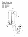
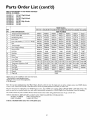
Parts Order List......................................................................................................
26-27
Customer
Thank
Responsibilities
• This manual contains instructions for the installation, operation, and maintenance of the gas-fired water heater. It also
contains warnings through out the manual that you must read
and be aware of. All warnings and all instructions are essential
to the proper operation of the water heater and your safety.
Since we cannot put everything on the first few pages, READ
THE ENTIRE MANUAL BEFORE ATTEMPTING TO
INSTALL OR OPERATE THE WATER HEATER.
• The installation must conform with the instructions in this
manual; gas company rules; and Local Codes, or in the
absence of Local Codes, with the latest edition of the National
Fuel Gas code, ANSI Z223.1, also referred to as NFPA 54.
This publication is available from your local government or
public library or gas company or by writing NFPA,
Batterymarch Park,Quincy, MA 02269.
• If after reading this manual you have any questions or do not
understand any portion of the instructions, call the Sears
Service Center.
• Carefully plan the place where you are going to put the water
heater. Correct combustion, vent action, ana vent pipe installation are very important in preventing death from possible
carbon monoxide poisoning and fires.
Examine the location to ensure the water heater complies with
the "Facts to Consider About the Location" section in this
You
for purchasing
a Sears water heater.
Properly installed and maintained,
it should give you years of
trouble free service. If you should decide that you want the new
water heater professionally installed by Sears call the local Sears
Service Cemer or any Sears store. They will arrange for prompt,
quality installation by Sears authorized contractors.
Abbreviations
Found In This Instruction
Manual
C.S.A.. - Canadian Standards Association
A.N.S.I. - American National Standards Institute
N.EP.A. - National Fire Protection Association
AWARNING
This gas-fired water heater is design certified by CSA
INTERNATIONAL under American National Standard/CSA
Standard for Gas Water Heaters ANS Z2 .10. --CSA 4.
(latest edition). The installation must conform with this
manual, Local Codes and with the latest edition of the
National Fuel Gas Code, ANSI Z223.1.
This publication is availablefrom your localgovernment or
public library, gas company, or by writing NFPA,
Batterymarch Park, Quincy,MA 02269.
manual.
• For California installation this water heater must be braced,
anchored, or strapped to avoid falling or moving during an
earthquake. See instructions for correct installation procedures. Instructions may be obtained from your local dealer,
wholesaler, public utilities or California Office of the State
Architect, 400 P Street, Sacramento, CA 95814.
• Complies with SCAQMD rule #1121 and districts having
equivalent NOx requirements.
• Read the "Safety Precautions" section, pages 2 through 4 of
this manual first and then the entire manual carefully. If you
don't follow the safety rules, the water heater will not operate
properly.
It could cause DEATH,
SERIOUS
BODILY
INJURY AND/OR
PROPERTY DAMAGE.
Product
Specifications
DIMENSIONS IN INCHES
TANK
CAPACITY
IN GALLONS
TYPE
OF
GAS
153,332111
39
NATURAL
33,000
34.0
153.332161
153.332319
39
NATURAL
33,000
30
NATURAL
30,000
153.332363
30
NATURAL
153.332419
40
NATURAL
153.332463
40
NATURAL
50
NATURAL
MODEL
NUMBER
153.332563
RECOVERY RATE
GALS. PER HOUR
@90°F RISE
MINIMUM
DIAMETER
HEIGHT TO
JACKETTOP
y'
24"
36_"
34.0
3"
24"
36_"
31.0
3"
16"
56"
30,000
31.0
3"
16"
56"
32,000
33.0
3"
18"
56_"
32,000
33.0
3"
18"
56_"
32,000
33.0
3"
20"
56_"
B.T.U.
RATE
6
VENT
PIPE
Materials
Materials
and Basic Tools Needed
Needed
To simplify the installation
Sears has available the installation
parts shown below. You may or may not need all of these materials, depending on your type of installation.
Gas
Water Heater
Installation
Kit
WATER HEATER STAND 24"x24"xl 8"
FOR USE WITH WATER HEATERS
INSTALLED IN RESIDENTIAL
GARAGES HAVING A DIAMETER 24"
OR LESS AND A RATED CAPACITY 75
GALLONS OR LESS
@
!
llI'l
o
VENT
ELBOW
EXPANSION
TANKS
FOR THERMAL
EXPANSION
CONDITIONS AVAILABLE IN
2 GALLON AND 5
GALLON CAPACITY
THROUGH
LOCAL
SEARS STORE OR
SERVICE CENTERS
WATER HEATER INSTALLATION KIT WITH FLEXIBLE CONNECTORS
FOR
3/4" OR I/2" THREADED
OR COPPER PLUMBING
f
k
VENT
WATER HEATER HEAT
TRAPS HELP REDUCE HEAT
LOSS DUE TO THERMAL
SYPHONING
PIPE
Basic Tools
DRAIN PANS AVAILABLE IN 20"
DIAMETER FOR WATER HEATERS
HAVING A DIAMETER 18" OR LESS,
24" DIAMETER FOR WATER HEATERS
HAVING A DIAMETER OF 22" OR
LESS, AND AVAILABLE IN 28" DIAMETER FOR WATER HEATERS HAVING
A DIAMETER 26" OR LESS
ADDITIONAL
TOOLS NEEDED
WHEN SWEAT SOLDERING
You may or may not need all of these tools, depending on your
type of installation. These tools can be purchased at your local
Sears store.
•
•
•
•
•
•
•
FLEXIBLE WATER
HEATER GAS CONNECTOR WITH
FITTINGS
Tubing Cutters or Hacksaw
Propane Torch
Soft Solder
Solder Flux
EmeryCIoth
Wire Brushes
Pipe Wrenches (2) 14"
Screwdriver
Tin Snips
6 Foot Tape of Folding Rule
Garden Hose
Drill
Pipe dope or Teflon Tape
HACKSAW
GARDEN
HOSE
6 FOOT
TAPE
_RE
PIPE
WRENCH
SLOT-HEAD
SCREWDRIVER
__1
PHILLIPS
BRUSH
J2 _IRE
BRUSH
SCREWDRIVER
TORCH
PROPANE
TIN SNIPS
ROLL OF LEAD FREE
SOFT SOLDER
ROLL OF TEFLON TAPE
(USE ONLY ON WATER
CONNECTIONS)
PIPE DOPE (SQUEEZE TUBE)
(USE FOR WATER AND
GAS CONNECTIONS)
DRILL
ROLL OF EMERY
CLOTH
7
SOLDER FLUX
TUBING
CUTTER
Installation
Removing
Instructions
the Old Water
Heater
Disconnect
the vent pipe from the draft hood where
they connect to the water heater. In most installations
the vent pipe can be lifted off after any screw or other
attached devices are removed.
Dispose of the draft
hood. The new water heater has the draft hood which
must be used for proper operation.
Turn "OFF" the gas supply to the water heater.
AWARNING
If the main gas line--all
gas appliances is
used, also shut "OFF" the gasat each appliance. Leave all
gas appliances shut "OFF" until the water heater installation iscomplete.
®
®
the
"OFF"
QTurn
water to the water
heater. Some installations
require that
the water be turned off to the entire
house.
relnoved.
b. If you have galvanized pipe to the water
GCheck
a,gain to make sure the gas supply
is ' OFF
to the water heater. Then disconnect the gas supply connection from
the gas control valve.
G
heater, loosen the two galvanized pipes
with a pipe wrench at the union in each
line. Also disconnect the piping remaining to the water heater. These pieces
should be saved since they may be needed when reconnecting
the new water
heateL Disconnect the temperature-pressure relief valve drain line. When the
water heater is drained, disconnect the
hose from the drain valve. Close the
drain valve. The water heater is now
completely disconnected and ready to be
removed.
Attach a hose to the water heater drain
valve and put the other end in a floor
drain or outdoors. Open the water heater
drain valve. Open a nearby hot water
faucet which will relieve pressure in the
water heater and speed draining.
AWARNING
®
a. If you have copper piping to the water
heater, the two copper water pipes can
be cut with a hacksaw approximately
four inches away from where they connect to the water heater. This will avoid
cutting
off the pipes
too short.
Additional cuts can be made later if necessary. Disconnect the temperature-pressure relief valve drain line. When the
water heater is drained, disconnect the
hose from the drain valve. Close the
drain valve. The water heater is now
completely disconnected and ready to be
1
The water passing o_alve
may be extremely
hot. To avoid being scalded, make sure all connections are
tight and that the water flow is directed away from any
person.
I
ACAUTION
I
Mineral buildupor sere
accumulated in the I
old water heater. This causesthe water heater to be much ]
heavier than normal and this residue, if spilled out, could
causestaining.
1
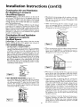
Installation
Instructions
Facts to Consider
Location
About the
You should carefidly
water heater, because
eration for the safety
the most economical
not for use in mobile
choose an indoor location for the new
the placement is a very important considof the occupants in the building and for
use of the appliance. This water heater is
homes or outdoor installation.
(cont'd)
• The location selection must provide adequate clearances for servicing and proper operation of the waterheater.
&WARNING
This water heater must not be installed directly on carpeting.
Carpeting must be protected by a metal or wood panel
beneath the appliance extending beyond the full width and
depth of the appliance by at least 3 inches (76.2mm) in an)
direction, or if the appliance is installed in an alcove or closet
the entire floor must be covered by the panel. Failure to bee(
this warning may result in a fire hazard.
Whether replacing an old water heater or putting the water
beater in a new location, the following critical points must he
observed.
• The location selected should be indoors as close as practical
to the gas vent or chimney to which the water heater vent is
going to be connected, and as centralized with tbe water
_iping system as possible. The water heater, as all water
eaters, will eventually
leak. Do not install without
adequate drainage provisions where water flow will cause
damage.
&WARNING
Minimum clearances between the water heater and combustible or non-combustible construction are I" at the sides
and roar, 4" at the front, and 6" from the vent pipe, Clearance
from the top of the jacket is 18" on most models. Note that a
lesser dimension may be allowed on some models. Refer to the
label on the water heater adjacent to the gas control valve for
all clearances.
ACAUTION
WATER HEATERS EVENTUALLY LEAK: Installation of the
water heater must be accomplished in such a manner that if
the tank or any connections should leak, the flow of water will
not cause damage to the structure. For this reason, it is not
advisable to install the water heater in an attic or upper floor.
When such locations cannot be avoided, a suitable drain pan
should be installed under the water heater. Drain pans are available at your local Sears store. Such a drain pan must be not
greater than I '/2inchesdeep, have a minimum length and width
of at least 2 inches greater than the water heater dimensions
and must be piped to an adequate drain. The pan must not
restrict combustion air flow. Under no circumstances is the
manufacturer or Sears to be held liable for any water damage
in connection with this water heater.
_2" MAX.
VENTILATION
AIR
OPENINGS
$
0
" IN MIN
TOP VID/V
,i
OF CLOSET
TOP VIEW I" MIN.
WITHOUT
DOOR
OF CLOSET
12" MAX
WITH DOOR
FRONT VIEW
OF DOOR
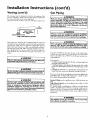
_,WARNING
AIR DUCT
Figure I I
INSTALLATIONS IN AREAS WHERE FLAMMABLE LIQUIDS
(VAPORS) ARE LIKELY TO BE PRESENT OR STORED
(GARAGES, STORAGE, AND UTILITY
AREAS, ETC):
Flammable liquids (such as gasoline, solvents, propane (LP) or
butane, etc.), all of which emit flammable vapors, may be
improperly stored or used in such areas. The gas water heater
pilot light or main burner can ignite such vapors. The resulting
flashbackand fire can cause death or seriousburns to anyone in
the area, as well as property damage.
If installation in suchareas is your only option, then the installation must be accomplished in a way that the pilot flame and
main burner flame are elevated from the floor at least 18 inches.
While this may reduce the chancesof flammable vapors from a
floor spill being ignited, gasolineand other flammable substances
should never be stored or used in the same room or area containing a gas water heater or other open flame or spark producing appliance.
NOTE: Flammable vapors may be drawn by air currents from
other areas of the structure to the appliance.
&WARNING
A gas water heater cannot operate properly without the correct amount of air for combustion. Do not install in a confined
area such a closet, unlessyou provide air as shownin the "Facts
to Consider About the Location" section. Never obstruct the
flow of ventilation air. If you have any doubts or questions at all,
call your gas company. Failure to provide the proper amount of
combustion air can result in a fire or explosion and can cause
DEATH, SERIOUS BODILY INJUR% OR PROPERTY DAHAGE.
AWARNING
If this water heater will be used in beauty shops, barber shops,
cleaning establishments, or self-service laundries with dry
cleaning equipment, it is imperative that the water heater or
water heaters be installed so that combustion and ventilation
air be taken from outside these areas. Refer to the "Facts to
Consider About the Location" section of this manual and also
the latest edition of the National Fuel Gas Code, ANSI Z223. I,
also referred to as NFPA 54 for specificsprovided concerning
air required.
AWARNING
Propellants of aerosol sprays and volatile compounds, (cleaners, chlorine based chemicals, refrigerants, etc.) in addition to
being highly flammable in many cases, will also change to corrosive hydrochloric acid when exposed to the combustion
products of the water heater. The results can be hazardous,
and also cause product failure.
9
Installation
Instructions
(cont'd)
Combustion
Air and Ventilation
for Appliances Located in
Unconfined Spaces
Unconfined
Space is a space whose volume is not less than 50
cubic feet per 1,000 Btu per hour of the aggregate input rating
of all appliances installed in that space. Rooms communicating
directly with the space in which the appliances are installed,
through openings not furnished with doors, are considered a
part of the unconfined space
In unconfined spaces in buildings, infiltration may be adequate
to provide air for combustion,
ventilation and dilution of flue
gases. However, in buildings of tight construction
(for example,
weather stripping, heavily insulated, caulked, vapor barrier, etc.),
additional
air may need to be provided using the methods
described
in Combustion
Air and Ventilation
for Appliances
Located in Confined Spaces, b.
I. When directly communicating
with the outdoors, each opening shall have a minimum free area of 1 square inch per 4,000
BTU per hour of total input rating of all equipment
in the
enclosure. (See Figure 3.)
2. When communicating
with the outdoors
through vertical
ducts, each opening shall have a minimum
free area of 1
square inch per 4,000 BTU per hour of total input rating of
all equipment in the enclosure. (See Figure 4.)
Combustion Air and Ventilation
for Appliances Located in
Confined Spaces
Confined
Space is a space whose volume is less than 50 cubic
feet per 1,000 Btu per hour of the aggregate input rating of all
appliances installed in that space.
a. ALL AIR FROM INSIDE BUILDINGS:
(See Page 9 Figure 1, and Figure 2 below)
The confined space shall be provided with two permanent
openi_ngs communicating
directly with an additional room(s)
of sufficient
volume so that the combined
volume of all
spaces meets the criteria for an unconfined
space. The total
input of all _as utilization equipment
installed in the combined space shall be considered in making this determination.
Each opening shall have a minimum free area of one square
inch per 1,000 BTU per hour of the total input rating of all
gas utilization equipment
in the confined space, but not less
than 100 square inches. One opening shall commence within
12 inches of the top and one commencing within 12 inches
of the bottom of the enclosure.
Figure 4 ]
3. When communicating
with the outdoors through horizontal
ducts, each opening shall have a minimum
free area of 1
sguare inch per 2,000 BTU per hour of total input rating of
all equipment in the enclosure. (See Figure 5.)
___UrLEr
_
[
b. ALL AIR FROM OUTDOORS:
(see Figures 3-5)
The confined space shall be provided with two permanent
openings, one commencing
within 12 inches of the top and
one commencing
within 12 inches from the bottom of the
enclosure. The openings shall communicate
directly, or by
ducts, with the outdoors or spaces (crawl or attic) that freely
communicate with the outdoors.
Figure
5
]
CHbM_EY O_ GA_ VEN_
_
A_n OUCh.
..........
4,
When ducts are
area as the free
The minimum
shall not be less
5.
Louvers and Grilles: In calculating free area, consideration
shall be given to the blocking effect of louvers, grilles or
screens protectin_ openings. Screens used shall not be smaller
than ¼ inch mesh. If the free area through a design of louver
or grille is known, it should be used in calculating the size
opening required to provide the free area specified. If the
design and free area is not known, it may be assumed that
wood louvers will be 20-25 percent free area and metal louvers
and grilles will have 60-75 percent free area. Louvers and
grilles shall be fixed in the open position or interlocked with
the equipment so that they are opened automatically during
equipment operation.
used, they shall be of the same cross-sectional
area of the openings to which they connect.
short side dimension of rectangular air ducts
than 3 inches. (See Figure 5.)
6. Special Conditions
Created by Mechanical
Exhausting or
Fireplaces: Operation
of exhaust fans, ventilation systems,
clothes dryers or fireplaces may create conditions requiring
special attention to avoid unsatisfactory operation of installed
gas utilization equipment.
I Figure 3 ]
10
Installation
Water
Instructions
(cont'd)
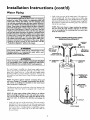
Piping
Look at the top cover of the water heater. The cold water
inlet is marked cold. Put two or three turns of teflon tape
around the threaded end of the threaded-to-sweat
coupling
and around both ends of the ¼" threaded nipple. Using flexible connectors, connect the cold water pipe to the coldwater
inlet of the water heater.
AWARNING
HOTTER WATER CAN SCALD: Water heaters are intended to
_reduce hot water. Water heated to a temperature which will
satisfyclothes washing,dish washing,and other sanitizing needs
can scald and permanently injure you upon contact. Some peofie are more likely to be permanently injured by hot water than
others. These include the elderly, children,the infirm, or physical.
lylmentally handicapped.If anyone usinghot water in your home
fits into one of these groups or if there is a local code or state law
requiring a certain temperature water at the hot water tap, then
_u must take special precautions.In addition to usingthe lowest
)ossibletemperature setting that satisfiesyour hot water needs,
a means such as a mixing valve, shouldbe usedat the hot water
taps used by these people or at the water heater. Mixing valves
are available at plumbing supplyor hardware stores.Follow manufacturers instructions for installation of the valves. Before
changing the factory setting on the thermostat, read the
"Temperature Regulation" section in this manual.
NOTE: This water heater is super insulated to minimize
heat loss from the tank. Further reduction in heat loss
can be accomplished by insulating the hot water lines
from the water heater.
INSTALLATION
COMPLETED USING
SEARS INSTALLATION
KIT
SHUTOFF
CONNECTORS
FLEXIBLE WATER
AWARNING
This water
heater_connected
heating systems or component(s)
potable water heating appliance.
I
used with
be introduced
suc_reatment
water heating
into a potable
THREADED TO
SWEAT COUPLING
]
appliances
water
1
_314"THREADED
NIPPLE
/
40T
COL
If a water heater is installed in a closed water supply system;
such as one having a back-flow preventer, check valve, water
meter with a check valve, etc.., in the cold water supply; means
shall be provided to control thermal expansion.
Contact
the
local utility or local Sears Service Center on how to control this
situation.
NOTE: To _protect against untimely corrosion of hot and
cold water tlttings, it is strongly recommended that di-electric unions or couplings be installed on this water heater
when connected to copper pipe.
[]
The illustration shows the attachment of the water piping to the
water heater. The water heater is equipped with 5a inch water
con
COLD INLET
WATER LINE
THREADED TO
SWEAT COUPLING
314"THREADED_-_
NIPPLE
of boilers/
shall never|
heating system,
\'-
OUTLET
TO HOUSE
to any|
a non-|
"WARN,.G
Toxic chemicals
or non-potable
HOT
--/
]
[_E
I_
--TEMPERATUREPRESSURE
RELIEF VALVE
<-
--
DISCHARGE
PIPE (Do not cap
or plug)
Ilections,
NOTE: If using copper tubing, solder tubing to an adapter
before attaching the adapter to the cold water inlet connection. Do not solder the cold water supply line direcdy to the
cold water inlet. It will harm the dip tube and damage the
tank.
6" AIR GAP
•
Look at the top cover of the water heater. The water outlet is
marked hot. Put two or three turns o| teflon tape around the
threaded end of the threaded-to-sweat
coupling and around
both ends of the _" threaded nipple. Using flexible connectors, connect the hot water pipe to the hot water outlet on
the water heater.
FLOOR
11
DRAIN
Installation
Instructions
Temperature-Pressure
(cont'd)
Relief Valve
_,WARNING
AWARNING
At the time of manufacture this water heater was provided
with a combination temperature-pressures relief valve certified
by a nationally recognized testing laboratory that maintains
periodic inspection of production of listed equipment or materials, as meeting the requirements
for Relief Valves and
Automatic Gas Shutoff Devicesfor Hot Water Supply Systems,
and the latest edition of ANSI Z21.22 and the code requirements of ASME. If replaced, the valve must meet the requirements of local codes,but not less than a combination temperature and pressure relief valve certified as meeting the requirements for Relief Valves and Automatic Gas Shutoff Devicesfor
Hot Water Supply Systems, ANSI Z21.22 by a nationally recognized testing laboratory that maintains periodic inspection of
production of listed equipment or materials.
The valve must be marked with a maximum set pressure not
to exceed the marked hydrostatic working pressure of the
water heater (150 Ibs./sq.in.) and a discharge capacity not less
than the water heater input rate as shown on the model rating
plate. (Electric heaters - watts divided by 1000 x 3415 equal
BTU/Hr. rate.)
Your local jurisdictional authority, while mandating the use of a
temperature-pressure relief valve complying with ANSI Z2h22
and ASME, may require a valve model different from the one
furnished with the water heater
Compliance with such local requirements must be satisfied by
the installer or end user of the water heater with a locally prescribed temperature-pressure relief valve installed in the designated opening in the water heater in place of the factory furnished valve.
For safe operation of the water heater, the relief valve must not
be removed from it'sdesignated opening or plugged.
The temperature.pressure relief valve must be installeddirectly
into the fitting of the water heater designatedfor the relief valve.
Position the valve downward and provide tubing so that any dis- i
charge will exit only within 6 inches above, or at any distance
below the structural floor Be certain that no contact is made
with any live electrical part. The dischargeopening must not be
_locked or reduced in size under any circumstances.Excessive
length, over 30 feet, or use of more than four elbows can cause
restriction and reduce the dischargecapacity of the valve.
No valve or other obstruction is to be placed between the relief
valve and the tank. Do not connect tubing directly to discharge
drain unlessa 6" air gap is provided. To prevent bodilyinjury, haz.
ard to life, or property damage, the relief valve must be allowed
to dischargewater in quantities shouldcircumstancesdemand. If
the discharge pipe is not connected to a drain or other suitable
i means, the water flow may causeproperty damage.
The Discharge Pipe:
• Must not be smaller in size than the outlet pipe size of the
valve, or have any reducing couplingsor other restrictions.
Must not be plugged or blocked.
Must be of material listed for hot water distribution.
Must be installed so as to allow complete drainage of both
the temperature-pressure relief valve, and the discharge
pipe.
Must terminate at an adequate drain.
Must not haveany valve between the relief valve and tank.
The temperature-pressure
relief valve must be manually
operated at least once a year. Caution should be taken to
ensure that (I) no one is in front of or around the outlet of
the temperature-pressure relief valve discharge line, and (2)
the water manually discharged will not cause any bodily
injury or property damage because the water may be
extremely hot.
If after manually operating the valve, it fails to completely
reset and continues to release water, immediately close the
cold water inlet to the water heater, follow the draining
nstructions,
and replace the temperature-pressure
relief
valve with a new one.
HOT
COLD
VALVE
RELIEF VALVE
[]
(Do not cap or plug)
6" AIR GAP
FLOOR
ORA|N
I
RELIEF VALVE OPENING
"THIS WATER HEATER IS PROVIDED WITH A COMBINATION TEMPERATURE-PRESSURE RELIEF VALVE. FOR SAFE OPERATION OF THE
WATER HEATER, THE RELIEF VALVE(S) MUST NOT BE REMOVED
FROM ITS DESIGNATED POINT OF INSTALLATION OR PLUGGED."
YOUR LOCAL 3UR_SDICT_ONALAUTHORITY,WH_LE MANDATING THE
USE OF A TEMPERATURE-PRESSURE RELIEF VALVE COMPLYING
WITH ANSI Z21.22 AND ASME, MAY REQUIRE A VALVE MODEL DIFFERENT FROM THE ONE FURNISHED WITH THE WATER HEATER.
COMPLIANCE WITH SUCH LOCAL REQUIREMENTS MUST BE SATISFIED BY THE INSTALLER OR END USER OF THE WATER HEATER
WITH A LOCALLY PRESCRIBED TEMPERATURE-PRESSURE RELIEF
VALVE INSTALLED IN THE DESIGNATED OPENING IN THE WATER
HEATER.
SEE MANUAL HEADING--"TEMPERATURE-PRESSURE
RELIEF
VALVES" FOR INSTALLATION AND MAINTENANCE OF REUEF VALVE,
DISCHARGE LINE AND OTHER SAFETY PRECAUTIONS.
12
Installation
Filling
the Water
Instructions
(cont'd)
Heater
For proper venting in certain installations, a larger diameter vent
pipe may be necessary. Due to great variances in installations,
unforeseeable by the manufacturer of the water heater, you must
consult your gas company to aid you in determining the proper
venting for your water heater from the vent tables in the latest edition of the National Fuel Gas Code ANSI Z223.1, also referred to
as NFPA 54.
ACAUTION
Never usethis water heater unlessit Jscompletelyfilledwith I
I water. To prevent damageto the tank, the tank must be filled I
[ with water. Water must flow from the hot water faucet
J beforeturning "ON" gasto the water heater.
To fill the water heater with water:
Close the water heater drain valve by turning the handle to
the right (clockwise). The drain valve is on the lower front of
the water heater.
Open the cold water supply valve to the water heater.
NOTE: The cold water supply valve must be left open
when the water heater is in use.
To insure complete filling of the tank, allow air to exit by
opening the nearest hot water faucet. Allow water to run
until a constant flow is obtained. This will let air out of the
water heater and the piping.
Check all new water piping for leaks. Repair as needed.
Check the venting system for signs of obstruction or deterioration
and replace if needed.
The combustion
and ventilation
air flow must not be obstructed.
AWARNING
Obstructedor deteriorated vent systemsmay presenta serious
healthrisk or asphyxiation.
• Place the draft hood legs in the receiving holes on the top of
the water heater. The legs will snap in the holes to give a tight
fit.
• Place the vent pipe over the draft hood. With the vent pipe
in position, drill a small hole through both the vent pipe and
draft hood. Secure them together with a sheet metal screw.
Venting
AWARNING
VENT DAMPERS • Any vent damper, whether it is operated
thermally or otherwisemust beremoved ifits useinhibitsproper draftingof the water heater.
Thermally Operated Vent Dampers:Gas-firedwater heaters
havingthermal efficiencyin excessof 80%may producea relativelylowfluegastemperature.Suchtemperaturesmay not be
high enough to properly open thermally operated vent
dampers.Thiswould causespillageof fluegasesand maycause
carbonmonoxidepoisoning.
Ventdampersmust bear evidenceof certificationascomplying
with the latest edition of American National StandardANSI
7.21.68(ANSI 7_21.66& 67, respectively,
coverelectricallyand
mechanicallyactuatedventdampers).Beforeinstallationofany
vent damper,consultyourlocalSearsServiceCenteror the gas
utilityforfurther information.
DRAFT
HOOD
_Jr
, "--_fi, _
VENT_J
ai__SCRE_'-J
1.40_
!
DRAFT
HOOD
VENT TO OUTDOORS
J_- OR CHIMNEY
DRAFT
AWARNING
J
The water heater with dreft hood installedmust be properly
ventedto a chimneywhichterminatesoutdoors_Never oper-J
Jate the water heater unlessit isvented to the outdoorsand has
Jadequateair supplyto avoidrisksof improperoperation,explo-J
I sionor asphyxiation.
!
AWARNING
To insure proper venting of this gas-firedwater heater, the
correct vent pipediameter mustbe utilized.Any additionsor
deletionsof other gasapplianceson a common vent with this
water heater may adverselyaffectthe operation of the water
heater.Consultthe localSearsService Center or gasutility if
any suchchangesare planned.
l
13
AWARNING
1
The ventpipefrom thrust
be no lessthan the I
diameter of the draft hood outlet on the water heater, andI
must slopeupward to the chimneyat least '/4inchper linear[
foot.
j
Installation
Instructions
Venting (cont'd)
(cont'd)
Gas Piping
All vent gases must be completely vented to the outdoors of the
structure (dwelling). Install only the draft hood provided with
the new water heater and no other draft hood.
Vent pipes must be secured at each joint with sheet metal screws.
_,WARNING
Hake sure the gassupplied is the same type listed on the
model rating plate. The inlet gaspressuremust not exceed
10.5in. water column (2.6kPa)for natural gasor 13 in. water
column (3.2kPa) for propane(LR) gas.The minimum inlet
gaspressurelistedon the model rating plate is for the purposeof inputadjustment.
TO
CHIMNEY
RISE PER LINEAR
_,WARNING
If the gascontrol valveissubected to pressuresexceeding½
poundper squareinch(3.5kPa), the damageto the gascontro valvecouldresult in a fire or explosionfrom lealdnggas.
1
VENT PIPE INSTALLATION
_, WARNING
There must be a minimum of 6" clearance between single wail
vent pipe and any combustible material. Fill and seal any clearance between single wall vent pipe and combustible material
with mortar mix, cement, or other noncombustible substance.
For other than single wall, follow vent pipe manufacturer's clearance specifications. To insure a tight fit of the vent pipe in a
brick chimney, seal around the vent pipe with mortar mix
cement.
J
I If the main gasline shutoffservingall gasappliances is used J
J o turn OFF the.gasat eachappliance..
Leave.all gasapphJancesshutoff untJIthe water heater nstallatmnmcomplete. J
A gas line of sufficient size must be run to the water heater.
Consult the latest edition of National Fuel Gas Code ANSI
Z223.1, also referred to as NFPA 54 and the gas company concerning pipe size.
_,WARNING
I
Failureto haverequired clearancesbetween vent pipingand J
combustiblematerial will result in a fire hazard.
I
There must be:
• A readily accessible manual shut offvalve in the gas supply line
serving the water heater, and
• A drip let (sediment trap) ahead of the gas control valve to help
prevent dirt and foreign materials from entering the gas control
valve.
&WARNING
I
• A flexible gas connector or a ground joint union between the
shutoffvalve and control valve to permit servicing of the unit.
Be surevent pipeisproperly connectedto preventescapeof
dangerousflue gaseswhichcouldcausedeadlyasphyxation.
Be sure to check all the gas piping for leaks before li8hting the
water heater. Use a soapy water solution, not a match or open
flame. Rinse offsoapy solution and wipe dry.
_,WARNING
Standard
level.
Chemical vapor corrosionof the flue and vent system may
occurif air for combustioncontainscertain chemicalvapors.
Spray can propellants,cleaningsolvents,refrigerator and air
conditioner refrigerants, swimming pool chemicals,calcium
and sodiumchloride,waxes,bleach,and processchemicalsare
typicalcompoundswhichare potentiallycorrosive.
Models
are for installation
High Altitude Models
feet above sea level.
up to 3,300 feet above sea
are for installation
from 3,300
to 5,500
Ifa standard model is installed above 3,300 feet or a high altitude
model is installed, above 5,500 feet, the input rating must be
reduced at the rate of 4 percent for each 1,000 feet above sea level.
Contact your local Sears Service Center or gas utility for further
information.
The appliance and its gas connection must be leak
_, WARNING
tested
beforeplacingthe appliancein operation.
14
Installation
Instructions
(cont'd)
GAS PIPING
WITH
FLEXIBLE
CONNECTOR
,_ WARNING
•The applianceand its individualshutoffvalvemustbe disconnectedfrom the gassupplypipingsystemduringanypressure
testing of the gas system at test pressuresin excessof ½
poundper squareinch(3.5kPa).
•The appliancemustbe isolatedfrom the gassupplypipingsystem by closingits individualmanualshutoffvalveduring any
pressuretestingof the gassupplypipingsystemat test pressuresequalor lessthan _ poundper squareinch(3.5kPa).
_,WARNING
Use pipe joint compound
FLEXIBLEGAS CONNECTOR
GROUND
I
_LOOP
3,,T..(sD, ='Po
or teflon tape marked as being
,, __
resistant to the action of potro eum [Propane (LR)] gases.
SEDIMENT
IOINT_
CONTROLvALVE
TRAP
GAS PIPING WITH ALL BLACK
PIPE TO GAS CONTROL
A sediment trap shall be installed as close to the inlet of the
water heater as practical at the time of water heater installation.
The sediment trap shall be either a tee fitting with a capped nipple in the bottom outlet or other device recognized as an effective sediment trap. If a tee fitting is used, it shall be installed in
conformance
with one of the methods of installation shown
below.
GROUND JOINT
UNION(Optional)
IRON
BLACK PIPE
Connecting
the gas piping to the gas control valve of the water
heater can be accomplished by either of the two methods shown.
GAS
CONTROL
VALVE
AWARNING
Contaminants in the gas lines may cause improper operation
of the gas control valve that may result in fire or explosion.
Before attaching the gas line be sore that all gas pipe is clean
on the inside. To trap any dirt or foreign material in the gas
supply line, a drip leg (sometimes called a sediment trap)
must be incorporated in the piping. The drip leg must be
readily accessible. Install in accordance with the "Gas Piping"
section. Refer to the latest edition of the National Fuel Gas
Code, ANSI Z223.1, also referred to as NFPA 54.
15
3" m_in
•
DRIP LEG
(Sediment trap)
_1
CAP
Installation
Instructions
(cont'd)
Installation Checklist
BEFORE LIGHTING
THE PILOT:
VENT PIPE TO
OUTDOORS
OR CHIMNEY
Check the gas lines for leaks.
a. Use a soapy water solution• DO NOT test for gas leaks
usinga match or open flame•
b. Brush the soapy water solution on all gas pipes, joints and
fittings•
c. Check for bubbling soap. This means you have a leak.
Turn'OFF
gas andmake
the necessary repairs.
d. Recheck for leaks.
e. Rinse offsoapy solution and wipe dry.
SHUTOFF
t
VALVE
HOT
_.
COLD
UNION
Is the new temperature-pressure
relief valve properly installed
and piped to an adequate drain? See "Temperature-Pressure
Relief VaLve" section.
• Are the cold and hot water lines connected to the water
heater correctly? See "Water Piping" instructions in the
"Installation Instructions" section.
•
•
DRAFT
HOOD
GAS SUPPLY
PRESSURE
RELIEF VALVE
+
Is the water heater completely filled with water? See "Filling"
•
,
•
,
.
_
,
instructions
in the ++Installation
Instrucnons
section.
Will a water leak damage
anything?
Consider About the Location" section.
See the "Facts
SHUTOFF
VALVE
to
(Do
not cap or plug I
• Is there proper clearance between the water heater and anything that m!ght catch fire? See the "Facts to Consider About
the Location section.
•
Do you have adequate ventilation so that the water heater
will operate properly? See "Combustion
Air and Ventilation"
in the "Installation Instructions" section.
•
Is the draft hood vent piping properly secured? See "Venting"
6" AIR GAP
lnsrrtlCtlons
Ill the
Installation
Instructions
section.
•
Is there proper clearance between the vent pipe and anything
that might catch on fire? See "Venting" instructions in the
"Installation Instructions" section.
•
Is the vent pipe properly sloped and does the vent terminate
outdoors?
See "Venting"
instructions
in the "Installation
Instructions" section.
Do you need to call your gas company
and its hookup?
DRAIN VALVE
FLOOR DRAIN
I
to check the gas pipe
tJak_
7®
"7 '2 i-I'',,..,_,_'_
f,Ai
MODEL
16
,_.._ %_"_lt _L_.w-c.
I
we.
I
RATING
w_
I
PLATE
W_
Operating
Instructions
Lighting
IIWARNING
BEFORE LIGHTING [PROPANE (L.P.) GAS WATER
HEATERS]:Propane (L.R) gasis heavierthan air.Shouldthere
be a leak in the system,the gaswill settle near the ground.
Basements,crawl spaces,skirted areasunder mobile homes
(evenwhenventilated),closetsand areasbelowgroundlevelwill
serve as pockets for the accumulation of this gas. Before
attemptingto lightor relight the water heater'spilotor turning
on a nearby electricallightswitch,be absolutelysurethere isno
accumulatedgasin the area.Searchfor odor ofgasbysniffingat
groundlevelin the vicinityof the appliance.If odor isdetected,
followstepsindicatedat "For YourSafety"on the coverpageof
this manualthen leavethe premises.
Figure 6 I
Lighting and operating instructions are located on front of the
water heater, above or to one side of the gas control valve.
IIWARNING
AN ODORANT IS ADDED TO THE GAS USED
BY THIS WATER HEATER.
FOR YOUR SAFETY
IF YOU SMELL GAS:
• Do not try to light anyappliance.
• Do not touch anyelectricalswitch;do not useany phonein
your building.
• Immediately callyour gassupplierfrom a neighbor's phone.
Followthe gassuppliersinstructions.
• If you cannot reach your gas supplier,call the fire department.
A WARNING
DO NOT force the gascontrol knob, Use onlyyour handto
pushit downto light the pilot, or to tom it to "ON", "OFF"
or "PILOT". Never usea tool suchas a lever,wrench or pliers. Do not hit or damage the knob. A damaged knob may
result in an explosionand serious injury.If you haveproblem
turningthe knob, call the gassupplierimmediately.
Figure
CHECK
8 ]
FOR LEAKS
Be sure to check all your gas pipes for leaks before lighting your
water heater. Use a soapy water solution, not a match or open
flame. Check the factory gas fittings after pilot is lit and gas control knob is still in "PILOT" position. Then, check the fittings
when the main burner is turned "ON". Use a soapy water solur
tion for this, too.
i
INNER
Figure 9 J
17
DOOR
Operating
Lighting
Instructions
label on the water
FOR YOUR
SAFETY
heater
(cont'd)
as it appears
READ
above
BEFORE
the thermostat
LIG
WARNING
If you do not follow these instructions exactly, a fire or explosion
may result causing property damage, personal injury or loss of life.
A. This appliancehas a pilot whichmust be lighted by
hand.Whenlightingthe pilot,followthese instructions
exactly.
B. BEFORELIGHTINGsmellall aroundthe appliancearea
for gas. Be sure to smell next to the floor because
somegasis heavierthanair and willsettleon thefloor.
WHATTODO IF YOUSMELLGAS
• Do not tryto lightanyappliance.
• Do not touch any electric switch; do not use any
phonein yourbuilding.
• Immediatelycall yourgas supplierfrom a neighbor's
phone.Followthe gassupplier'sinstructions.
LIGHTING
• If you cannotreachyour gas supplier,call the fire
department.
C. Useonlyyourhandto pushin or turnthe gas control
knob.Never usetools. If the knobwill not pushin or
turnby hand,don'ttry to repairit, call a qualifiedservice technician.Forceor attemptedrepair may result
in a fire or explosion.
D. Do not usethis applianceif any part has been under
water.Immediatelycall a qualified servicetechnician
to inspecttheapplianceand to replaceany partof the
controlsystemand any gas controlwhichhas been
underwater.
INSTRUCTIONS
1. STOP!Readthe safetyinformationaboveon thislabel.
2. Removeouterdoor.
3. Set the thermostat to lowest setting by turning the
watertemperaturedial clockwise,(F-_) to its lowest
temperaturesetting(witharrowon dial)as shown.DO
9. Push in control knob all the way and hold down.
Immediatelylight the pilot with a match.Continueto
hold controlknob in for about one (1) minute after
the pilot is lit. Releaseknob and it will popback up.
Pilot shouldremainlit. If it goes out, repeat steps3
through8.
• If knobdoes not pop up when released,stop and
immediatelycall your service technicianor gas
supplier.
• If the pilot will not stay lit after several tries,
depressand turnthe gas controlknobclockwise
NOT FORCE,
4. Turngas controlknobclockwise_)
to "OFF" position. Knob cannot be turned from "PILOT" to "OFF"
unlessknob is depressedslightly.DO NOT FORCE.
(Figure6, page17)
5. Wait five (5) minutesto clear out any gas. If you then
smell gas, STOP!Follow"B" in the safety information
above on this label. If you don't smell gas, go to the
nextstep.
6. Remove(or open) inner door located belowthe gas
controlunit.
7. Findpilot-followmetal THERMOCOUPLE / ....
_ : PLOTBURNER'
tube fromgascontrol.
VI :_
The pilot is locatedin
front of theburner.
_
_
to "OFF" andcall yourservicetechnician
or gassupplier.(Figure6, page17)
10. Replace(or close)inner door.Replaceouter door if
door does not cover gas controlon/off knobor ternperatureadjustmentknob.(Figureg, page17)
11. At armslen_lthaway,turngas controlknobcounterclockwise_
to the full "ON" position.Warning
do not use gas control knob to regulate gas
flow. (Figure8, page17)
12. At arms length away,set the thermostatto desired
setting. The mark ( • ) indicative of approximate
120°Fis preferredstarting point. Some local laws
may requirea lowerstartingpoint.If hotterwater is
desired,seeinstructionmanualand"warning" below.
13.Replacethe outerdoorif not replacedin step10.
8. If youdon'tsmellgas,turn knobon gascontrolcounter
clockwise_,
@
to "PILOT"position.(Figure7, page17)
WARNING
•Iotter water increasesthe risk of scald injury. Beforechanging temperaturesetting see instructionmanual.
TO TURN
OFF GAS TO APPLIANCE
2.Turngas controlknobclockwise__ J to "OFF" position. Knob cannotbe turned from "PILOT" to "OFF"
unless knob is depressed slightly. DO NOT FORCE,
3. Replaceouter door (if removed).
1. Set the thermostat to lowest setting by turning the
watertemperaturedial clockwise(F_)
to its lowest
temperaturesetting(with arrowon dial) as shown. DO
NOT FORCE,
.
:2 Ij
]8
Operating
Temperature
Instructions
(cont'd)
Regulation
Due to the nature of the typical gas water heater, the water temerature in certain situations may vary up to 30°F higher or
ro_werat the point of use such as, bathtubs, showers, sink, etc.
Turn the water temperature dial clockwise (_"_)
to decrease
the temperature,
or counterclockwise
(_'_)
to increase the
temperature.
This means that when the temperature adjustment dial is set at
the mark approximating
120°F, the actual water temperature at
any hot water tap could be as high as 150°F or as low as 90°E
Any water heater's intended purpose is to heat water. Hot water
is needed for cleaning (bodies, dishes, clothing). Hot water will
present a scald hazard. Depending on the time element, and the
people involved (normal adults, children,
toddlers,
elderly,
infirm, etc.) scalding may occur at different temperatures.
AWARNING
HOTTER WATERCAN SCALD:Water heatersare intendedto
producehot water. Water heatedto a temperature whichwill
satisfyclotheswashing,dishwashing,and other sanitizingneeds
canscaldand permanentlyinjureyou uponcontact.Some people are more likelyto be permanentlyinjuredbyhot water than
others.Theseincludetheelderly,children,the infirm,or physical.
ly/mentally handicapped.
If anyoneusinghotwater in yourhome
fitsintooneofthese groupsor ifthere isa localcodeor statelaw
requiring a certaintemperaturewater at the hot water tap,then
youmust take specialprecautions.
In additionto usingthe lowest
possible
temperaturesettingthat satisfiesyourhot water needs,
a meanssuchas a mixingvalve,shouldbe usedat the hot water
tapsusedby thesepeopleor at the water heater.Mixingvalves
are availableat plumbingsupplyor hardwarestores.Followmanufacturers instructionsfor installationof the valves. Before
changing the factory setting on the thermostat, read the
'q'emperatureRegulation"sectionin this manual.
PILOT LIGHTING
Set here before attempting
to light pilot.
A-Is
a thermostat
setting of approximately
120°E which will supply hot water at the
most economical
temperatures.
The
temperature
adjustment
knob can be
turned lower than 120°F if desired.
A-Is a thermostat setting of approximately
130°E
B-Is
a thermostat
140°E
setting of approximately
C-Is a thermostat setting of approximately
150°E
AWARNING
]
VERYHOT-
Never allow small children to use a hot water tap, or to draw I
their own bath water. Never leave a child or handicapped per- I
sonunattended in a bathtub or shower.
]
Is a thermostat setting of 160°F. It is
recommended that the dial be set lower
whenever possible.
NOTE: Water temperature range of 120°--140°F
mended by most dishwasher manufacturers.
The thermostat of this water heater has been factory set at its
lowest position, to reduce the risk of scald injury. It is adjustable
and must be reset to the desired temperature setting. The mark
(at) indicative of approximately 120°F is the preferred starting
point. Some states have a requirement for a lower setting. If you
need hotter water, follow directions for temperature adjustment,
but beware of the warnings in this section.
recom-
AWARNING
]
Should overheatingoccur or the gas supplyfail to shut off,
turn "OFF" the manual gascontrolvalveto the appliance.
19
Service
and Adjustment
Tank (Sediment)
Cleaning
Burner
Sediment
build-up
on the tank bottom
may create varying
amounts of noise, and if left in the tank will cause premature
tank failure. In some water areas, you may not be able to drain
all sediment deposits by simply draining the tank. In these cases
Mag-Erad (part no. 23600) can be used to help remove the sediment deposits. This may be ordered from the Sears Service
Center. For ordering, refer to the "Parts Order List" section.
Inspection
"WARNING
Do not usethisapplian_
hasbeenunderwater
Immediately call a Sears Service Technicianto inspectthe
applianceand to replace the gascontrol or any part of the
burnersystemwhichhasbeenunderwater.
At least once a year a visual inspection should be made of the
main burner and pilot burner. The drawing is for your reference.
Venting System Inspection
You should check for sooting which is not normal and will
impair proper combustion.
At least once a year a visual inspection should be made of the
venting system. You should look for:
• Obstructions
which could cause improper venting. The combustion and ventilation air flow must not be obstructed.
Damage or deterioration
which could cause improper venting or leakage of combustion products.
Rusted flakes around top of water heater.
"WARNING
Chemical vapor corrosion of the flue and vent system may
occurif air for combustioncontainscertain chemicalvapors.
Spray can propellants,cleaningsolvents,refrigerator and air
conditioner refrigerants, swimming pool chemicals,calcium
and sodiumchloride,waxes,bleach,and processchemicalsare
typicalcompoundswhichare potentiallycorrosive.
.WARNING
"WARNING
Soot build-upindicatesa problem that requires correction
beforefurther use.Turn "OFF" gasto water heater and leave
"OFF" until repairs are made, becausefailureto correctthe
causeof the sootingcan result in a fire or explosioncausing
DEATH, SERIOUS BODILY INJURY, OR PROPERTY
DAMAGE.
I
Obstructed or deterioratedvent systemsmay presenta serious
healthrisk or asphyxat on.
I
Burner Cleaning
"WARNING
]
Be sure the vent piping is properly connected to prevent|
escapeof dangerousflue gasseswhich could cause deadly|
asphyxiation.
In the event your burner needs cleaning, use the following
instructions:
]
If inspection of the burner shows that cleaning is required, turn
the gas control knob clockwise (f"_)
to the "OFF" position,
depressing slightly.
"WARNING
l
If after inspectionof_you
found sootingor ]
deterioration,somethingiswrong. Call the localgasutility to I
correct the problemand cleanor replacethe flue and venting
before resuming operation ofthe water heater.
NOTE: The knob cannot be turned from "PILOT" to "OFF"
unless knob is depressed slightly. DO NOT FORCE.
Loose deposits on or around the burner can be removed by carefully using the hose of a vacuum cleaner inserted through the
access door of the water heater. If the burner needs to be removed
for additional cleaning, call die Sears Service Center to remove
and clean the burner and correct the problem that required the
burner to be cleaned.
2O
Service
and Adjustment
Drain Valve Washer
Replacement
Draining
The water heater should be drained if being shut down during
freezing temperatures.
Also periodic draining and cleaning of
sediment from the tank may be necessary.
NOTE: For replacement, use a '_;' x '¥_" x X" thick washer
available at your nearest hardware store. For ordering replacement washers, refer to the "Parts Order List" section.
Turn the gas control knob to the "OFF" position.
CLOSE the cold water inlet valve to the water heater.
OPEN a nearby hot water faucet and leave open to allow for
draining.
Connect a hose to the drain valve and terminate to an
adequate drain.
OPEN the water heater drain valve to allow for tank draining.
NOTE: If the water heater is going to he shut down and
drained for an extended period, the drain valve should be
left open with hose connected allowing water to terminate
to an adequate drain.
Close thedrain valve.
Follow instructions
in the "Filling The Water Heater"
section.
Follow the lighting instructions in the "Lighting" section to
restart the water heater.
Temperature-Pressure
Valve Operation
The temperature-pressure
at least once a year.
(cont'd)
Turn "OFF" gas supply to water heater.
Follow "Draining" instructions.
Turning counter clockwise, remove the hex cap below the
screw handle.
Remove the washer and put the new one in place.
Screw the handle and cap assembly back into the drain valve
and retighten using a wrench. DO NOT OVER TIGHTEN.
Follow instructions
in the "Filling The Water Heater"
section.
Check for leaks.
Follow the lighting instructions in the "Lighting" section to
restart the water heater.
Relief
relief valve must be manually
_AP
ASSEMBLY
WASHER
operated
TEMPERATURE-PRESSURE
Housekeeping
Vacuum around
regular basis.
base of water heater for dust, dirt, and lint on a
AWARNING
DISCHARGE
INSTALLED IN SUITABLE AREA: To insure sufrmient ventilation and combustion air supply, proper clearances from the
water heater must be maintained. See "Facts to Consider
About the Location" section. Combustible materials such as
clothing, cleaning materials, or flammable liquids, etc. must
not be placed against or adjacent to the water heater which
can cause a fire.
PIPE
Failure to install and maintain a new properly listed temperature-pressure
relief valve will release the manufacturer
from any
claim which might result from excessive temperature or pressure.
AWARNING
If the temperature-pressure relief valve on the appliance
weepsor dischargesperiodically,this may be due to thermal
expansion. Your water heater may have a check valve
installed in the water line or a water meter with a check
valve.Consultthe SearsService Center for further information. Do not plugthe temperature-pressurerelief valve.
Service
Before calling for repair service, read the Start Up Conditions
and Operational
Conditions
found in the Troubleshooting
Guide of this manual.
If a condition persists or you are uncertain about the operation
of the water heater, let a qualified person check it out.
AWARNING
When checking the temperature-pressure relief valve operation, make sure that (I) no one is in front of or around the
outlet of the temperature-pressure relief valve discharge line,
and (2) that the water manually discharged will not cause any
property damage because the water may be extremely hot.
If after manually operating the valve, it fails to completely
reset and continues to release water, immediately close the
cold water inlet to the water heater, follow the draining
instructions, and replace the temperature-pressure
relief
valve with a new one.
Contact SEARS Repair Services
(1-800-469-4663).
21
at 1-800-4-MY-HOME
Troubleshooting
Guide
Start Up Conditions
CONDENSATION
THERMAL
EXPANSION
Whenever
the water heater is filled with cold water, a certain
amount
of condensation
will form while the burner is on. A
water heater may appear to be leaking when in fact the water is
condensation. This usually happens when:
• When a new water heater is filled with cold water for the
first time.
When gas burns and water vapor is produced
in water
heaters, particularly high efficiency models where flue temperatures are lower.
When you use large amounts of hot water in a short time
and the refill water is very cold.
Water supply systems may, because of such events as high line
pressure, frequent cut-oti;, the effects of water hammer among
others, have installed devices such as pressure reducing valves,
check valves, back flowpreventers,
etc...to control these types of
problems. When these devices are not equipped with an internal
by-pass, and no other measures are taken, the devices cause the
water system to be closed. As water is heated, it expands (thermal expansion) and closed systems do not allow for the expansion of heated water.
The water within the water heater tank expands as it is heated and
increases the pressure of the water system. If the relieving point of
the water heater's temperature-pressure
relief valve is reached, the
valve will relieve the excess pressure. The temperature-pressure
relief valve is not intended for the constant relief of thermal
expansion.
This is an unacceptable
condition
and must be
corrected,
Moisture from the products of combustion condense on the
cooler tank surfaces and form drops of water which may fall
onto the burner or other hot surfaces to produce a "sizzling" or
"frying" noise.
Excessive condensation
can cause pilot outage due to water running down the title tube onto the main burner and putting out
the pilot.
It is recommended
that any devices installed which could create
a closed system have a by-pass and/or the system have an expansion tank to relieve the pressure built by thermal expansion in
the water system. Expansion
tanks are available for ordering
through the Sears Service Center. Contact the local plumbing
inspector, water supplier, and/or the Sears Service Center for
assistance in controlling these situations.
Because of the suddenness and amount of water, condensation
water may be diagnosed as a "tank leak". After the water in the
tank warms up (about 1-2 hours), the condition should
disappear.
Do not assume the water heater is leaking until there has been
enough time for the water in the tank to warm up.
Thermal
Expansion Tank Specifications
Model
Number
An undersized water heater will cause more condensation.
The
water heater must be sized properly
to meet the family's
demands for hot water including dishwashers, washing machines
and shower heads.
Tank Capacity
In Gallons
153.331020
[153.331050
Excessive condensation may be noticed during the winter and
early spring months when incoming water temperatures are at
their lowest.
2
5
Expansion
Good venting is essential for a gas fired water heater to operate
properly as well as to carry away products of combustion
and
water vapor.
Dimensions in Inches
Diameter _ Length
8 inches
12_ inches
l i inches-14_inches
Expansion
Tank
Capacity
Needed
It is not uncommon to experience a small amount of smoke and
odor during the initial start-up. This is due to burning off of oil
from metal parts, and will disappear in a short while.
_" Male
_';Male
Tank Sizing Chart
Inlet*
Water
SMOKE/ODOR
Pipe Fitting
On Tank
Pressure
40psi
50psi
60psi
70psi
80psi
Water Heater Capacity
30
2
2
2
2
2
40
2
2
2
2
5
(Gallons)
50
2
66
5
2
5
5
5
5
5
5
82
5
5
5
5
5
*Highest recorded inlet water pressure in a 24 hour period or
regulated water pressure.
NOTE: Expansion tanks are pre-charged with a 40 psi air
charge. If the inlet water pressure is higher than 40 psi, the
expansion tank's air pressure must be adjusted to match that
pressure, but most not be higher than 80 psi.
22
Troubleshooting
Guide
(cont'd)
Operational
HOT
COLD
WATER
HEATER
SMELLY
(3)
COLDWATER
INLET FITTING
PRESSURE
REDUCING
VALVEWITH
BY-PASS
TANK
0)
Conditions
WATER
In each glasslined water heater there is installed at least one
anode rod (see parts section) for corrosion protection
of the
tank. Certain water conditions will cause a reaction between this
rod and the water. The most common complaint associated with
the anode rod is one of a "rotten egg smell". This odor is derived
from hydrogen sulfide gas dissolved in the water. The smell is
the result of four factors which must all be present for the odor
to develop:
1
(z)
PRESSURE
GAUGE
a. a concentration
of sulfate in the supply water.
b. little or no dissolved oxygen in the water.
c. a sulfate reducing bacteria within the water heater. (This
harmless bacteria is non-toxic to humans.)
d. an excess of active hydrogen in the tank. This is caused by
the corrosion protective action of the anode.
WATER
SHUTOFF
RECOMMENDED INSTALLATION
(VERTICAL MOUNTING)
Smelly water may be eliminated or reduced in some water heater
models by replacing the anode(s) with one of less active material,
and then chlorinating
the water heater tank and all hot water
lines. Contact Sears Service for further information concerning
an Anode Replacement Kit #9001453
and this Chlorination
Treatment.
FLOOR,CEILING
iols'r, ETc.
WATER HEATER
COLD WATER
INLET FITTING
HOT
If the smelly water persists after the anode replacement and chlorination treatment, we can only suggest that continuous chlorination and filtering conditioning equipment be considered to
eliminate the water problem.
STRAPPING
O)
PRESSURE
REDUCING
VALVE WITH
(I)
EXPANSION
BY-PASS
Do not remove the anode leaving the tank unprotected. By
doing so, all warranty on the water heater tank is voided.
INLET COLD
WATER
SHUTOFF
"AIR"
(z)
PRESSURE
GAUGE
STRANGE
WATER
FAUCETS
AWARNING
HYDROGEN GAS: Hydrogen gascan be producedin a hot
water systemthat hasnot beenusedfor a longperiodof time
(generally two weeks or more). Hydrogen gasis extremely
flammableand explosive.To preventthe possibilityof injury
under these conditions,we recommend the hot water faucet
be openedfor severalminutesat the kitchensinkbeforeany
electricalappliances
whichare connectedto the hot water system are used (suchas a dishwasheror washingmachine). If
hydrogen gasis present, there will probably be an unusual
soundsimilarto air escapingthrough the pipeas the hot water
faucet is opened.There must be no smokingor open flame
near the faucetat the time it isopen.
ALTERNATE RECOMMENDED
INSTALLATION
(HORIZONTAL
IN HOT
MOUNTING)
SOUNDS
Possible noises due to expansion and contraction
of some metal
_arts during periods of heat-up and cool-down do not represent
armful or dangerous conditions.
Condensation
causes sizzling and popping with the burner area
during heating and cooling periods and should be considered
normal. See "Condensation"
section.
23
Troubleshooting
Operational
(cont'd)
HIGH
Guide (cont'd)
Conditions
TEMPERATURE
SHUT
OFF
SYSTEM
WATER
This water heater is equipped with an automatic gas shut offsystern. The high temperature shut off is built into the gas control
valve. This system shuts off the gas supply to the water heater
burners when high water temperatures are present. It is nonresettable. If the high temperature shut offactivates, the gas control valve must be replaced. If this were to occur, turn "OFF" the
entire gas supply to the water heater. Contact the Sears Service
• If lower temperature settings will not lower the water temperature, call the Sears Service Center.
AWARNING
Shouldoverheating occur or the gassupplyfail to shut off,
NOT
•
•
•
•
AWARNING
HOTTER WATERCAN SCALD:Water heatersare intendedto
,roducehot water.Water heatedto a temperaturewhichwill
satisfyclotheswashing,dishwashing,and other sanitizingneeds
canscaldand permanentlyinjureyou uponcontact.Somepeofie aremore likelyto be permanentlyinjuredbyhot water than
others.Theseincludetheeldedy,children,the infirm,or physically/mentallyhandicapped.
If anyoneusinghot waterin your home
fitsintooneofthesegroupsor if thereisa localcodeor statelaw
requiring a certaintemperaturewaterat the hot water tap,then
,oumust takespecialprecautions.
In additionto usingthe lowest
_ssible temperaturesettingthat satisfies
your hot water needs,
a meanssuchasa mixingvalve,shouldbe usedat the hot water
tapsusedbythesepeopleor at the water heater.Mixingvalves
are availableat plumbingsupplyor hardwarestores.Followmanufacturersinstructionsfor installationof the valves.Before
changingthe factory setting on the thermostat, read the
"Temperature Regulation"
sectioninthis manual.
the manual gascontrol valveto the appliance.
ENOUGH
OR NO
HOT
HOT
• The temperature adjustment dial may be set too high. See the
"Temperature Adjustment" section.
NOTE: A period of time is necessary after an adjustment has
been made for the water temperature to reach the new temperature setting.
Center,
turn OFF
IS TOO
WATER
Check the manual gas shut offvalve to be sure it is open.
Check the pilot flame. It may have gone out. All models have
an opening behind the outer door for viewing the pilot.
If the pilot is not lit, follow the "Lighting" instructions in this
manual are located above the gas control valve on the water
heater to relight the pilot. If the water was extremely hot and is
now cold, the high limit safety temperature shut off may have
put out the burner and pilot. If the high temperature shut off
activates, the gas controlvalve must be replaced. Contact the
Sears Service Center.
Th e gas control knob must be turned to the ......
ON posmon.
The temperature adjustment dial may be set too low. See the
"Temperature Regulation" section.
The gas company can check the gas input to see if it is correct.
An underfired water heater will not heat water as quickly.
Look for leaking or open hot water faucets. Make sure all are
closed.
The cold water inlet temperature may be colder during the
winter months. It will take longer to heat the water and seem
like less hot water.
If you cannot find what is wrong, call the Sears Service Center.
AWARNING
Due to the nature of the typical gas water heater, the
water temperature in certain situations may be hotter
than the thermostat setting.
Short, frequent draws of hot water - especiallywith very
cold incoming water - can shock the thermostat into brief
operation resulting in hotter and hotter layers of water
closerto the top of the tank.
Changes in hot water usage patterns or raising the temperature differential between the cut-on of the thermostat and the cold water temperature will usuallyeliminate
the problem.
24
Troubleshooting
Guide (cont'd)
Leakage Checkpoints
Use this guide to check a "Leaking" water heater. Many suspected "Leakers" are not leaking tanks. Often the source of the water
can be found and corrected.
A CAUTION
I
Read this manual first. Then before checking the water I
heater make sure the gas supply has been turned I
"OFF", and never turn the gas "ON" before the tank is
completely full of water.
If you are not thoroughly familiar with your local gas codes your
water heater, and safety practices, contact the Sears Service
Cente_r to check the water heater.
A CAUTION
J
Never use this water heater unless it is completely filled J
with water. To prevent damage to the tank, the tank J
must be filled with water. Water must flow from the hot I
water faucet before turning "ON" gas to the water
heater.
Water at the draft hood is water vapor which has
condensed out of the combustion products. This is caused
by a problem in the vent, Contact the Sears Service
Center.
*Condensation may be seen on pipes in humid
pipe connections may be leaking.
weather
or
*The primary anode rod fitting may be leaking.
Small amounts of water from the temperature-pressure
relief valve may be due to thermal expansion or high
water pressure in your area.
O'The
temperature-pressure
the tank fitting.
Water from
slightly.
O'The
0
O
a
relief valve may be leaking at
drain valve may be due
tO
the valve opened
drain valve may be leaking at the tank fitting.
Combustion products contain water vapor which can
condense on the cooler surfaces of the tank. Droplets
form and drip into the fire or run on the floor. This is
common at the time of startup after installation and when
incoming water is cold.
Water in the water heater bottom or on the floor may be
from condensation, loose connections, or the relief valve.
DO NOT replace the water heater until a full inspection
of all possible water sources is made and necessary
corrective steps taken. Leakage from other appliances,
water lines, or ground seepage should also be checked.
NOTE: To check where threaded portion enters tank,
insert cotton swab between jacket opening and fitting.
If cotton is wet, follow "Draining" instructions in the
"Service and Adjustment" section and then remove
fitting. Put pipe dope or teflon tape on the threads
and replace. Then follow "Filling the Water Heater"
instructions in the "Installation Instructions" section.
25
Parts Order
THE ECONOMIZER
MODEL NUMBERS:
153.332111
153.332161
153.332319
153.332363
153.332419
153.332463
153.332563
39
39
30
30
40
40
50
TM
List
6 GAS WATER HEATERS
Gal. High Altitude
Gal.
Gal. High Altitude
Gal.
Gal. High Altitude
Gal.
Gal.
16
2
17
13
26
Parts Order
THE ECONOMIZER
MODEL NUMBERS:
153.332111
153.332161
153.332319
153.332363
153.332419
153.332463
153.332563
39
39
30
30
40
40
50
TM
List (cont'd)
6 GAS WATER HEATERS
Gal. High Altitude
Gal.
Gal. High Altitude
Gal.
Gal. High Altitude
Gal.
Gal.
Model Numbers
KEY
NO.
1
2
3
4
5
6
7
8
9
153.332111
153.332161
153.332319
PART DESCRIPTION
153.332363
153.332419
153.332463
153.332563
PART NUMBERS
Temperature-PressureReliefValve
Primary Anode Rod
9000071
9000071
9000071
9000071
9000071
9000071
9000071
9001822
9001822
9000279
9000279
9000279
9000279
9000279
Model Rati% Plate _
Drain Valve
0270118
0270118
0270118
0270118
0270118
0270118
0270118
9000254
9000254
9000254
9000254
9000254
9000254
9000254
Drain ValveWasher(Tu" x '_4"x ¼"thick)**
Pilot
9001584
9001584
9001584
9001584
9001584
9001584
9001584
9000285
9000285
9000285
9000285
9000285
9000285
9000285
Thermocoupie*
Pilot Tubin_ w/Fittin{_s
42-33900
42-33900
4_22-33900
9000278
42-33900
9000278
42-33900
9000278
42-33900
9000278
42-33900
9000278
9000278
9000278
Burner Orifice
0230150
0230150
0230181
0230182
0230122
0230129
0230129
(#43)HA
(#40)
(#41)HA
9002613
9002411
9002615
9002411
(#38)
9002615
(#38)
9002617
10
Drill Size
Manifold
(#42)HA
9002621
(#38)
9002621
11
Burner
9002411
9002411
9002613
9002411
9002411
9002411
12
13
Outer Door
Inner Door
9000351
9000281
9000351
9000281
9000351
9000281
9000351
9000281
9000351
9000281
9000351
9000281
9000351
9000281
14
GasControlValve
F145-1278
F145-1278
F145-1278
F145-1278
F145-1278
F145-1278
F145-1278
15
TemperatureAdjustmentKnob
F145-1280
F145-1280
F145-1280
F145-1280
F145-1280
F145-1280
F145-1280
16
17
18
#
Dip Tube
Flue Baffle
Draft Hood
Manual
9002374
9002852
9000272
9002374
9002852
9000272
9001852
9001852
9001852
9000360
9000272
9000360
9000272
9000360
9000272
9001852
9000360
9001852
9000360
#
Mag-Erad
OOO291666O
23600
*These parts are also available at most Sears retail stores.
**Also available at most hardware stores.
tReplaced only on return of damaged plate.
# Not Illustrated
Now that you have purchased your Gas Water Heater, should a need ever exist for repair parts or service, simply contact any SEARS Service
Center or call 1-800-4-MY-HOME
(1-800-469-4663).
Be sure to provide pertinent facts when you call or visit.
All parts listed may be ordered from any SEARS Service Center, most SEARS stores and by calling 1-800-366-PART (1-800-366-7247).
If the
parts you need are not stocked locally, your order will be electronically transmitted to a SEARS Repair Parts Distribution Center for handling.
The model number
WHEN
of your Gas Water Heater will be found on the model rating plate located near the gas control valve.
ORDERING
REPAIR PARTS, ALWAYS GIVE THE FOLLOWING
MODEL NUMBER
PART DESCRIPTION
PART NUMBER
NAME OF ITEM
THIS IS A REPAIR PARTS LIST, NOT A PACKING
LIST.
27
INFORMATION:
Warranty
About Your Warranty
THE PRICE OF YOUR WATER HEATER DOES NOT INCLUDE
A FREE CHECKUP SERVICE CALL. On Water Heater Installations
Arranged By Sears, Sears warrants the installation.
ON INSTALLATIONS NOT MADE BY SEARS AUTHORIZED
CONTRACTORS:
1. Your Sears warranty applies to the product only.
2. Sears does not warrant the installation.
3. A charge will be made on service calls due to poor or incomplete
installation. These include:
a. Adjusting thermostat
b. Lighting pilot
c. Leaks in pipes or fittings
d. Improper venting
e. Condensation
This manual is in non-technical language. It may help you avoid the
cost of a needless service call. Many service calls really aren't needed.
Such as when:
1. The gas is turned "OFF".
2. The pilot is out.
3. A gas or water leak is due to loose pipe or connections.
FULL ONE YEAR WARRANTY ON WATER HEATER
For one year from the date of purchase, when your Sears Kenmore water heater is installed and operated in a single-family
residence in accordance with the instructions in this manual, Sears will:
1. Repair defects in material or workmanship in this water heater, free of charge.
2. Furnish and install a new current model water heater of equal capacity and quality, free of charge, ifa leak occurs in the
tank.
LIMITED WARRANTY ON TANKS THAT LEAK
After one year and through 6 years from the date of purchase for water heaters used in a single-family
occurs in the tank, Sears will furnish a new current model water heater of equal capacity and quality.
for any installation.
residence, if a leak
You will be charged
If the water heater is subjected to commercial, institutional, industrial or use in residences of two families or more, the
above warranty coverage for tanks that leak is effective for 2 years from the date of purchase.
To obtain warranty service, SIMPLY CALL 1-800-4MY-HOME
product is in use in the United States."
(1-800-469-4663).
"This warranty applies only while this
This warranty gives you specific legal rights and you may also have other rights which vary from state to state.
SEARS, ROEBUCK AND CO., Dept. 817 WA, HOFFMAN ESTATES, IL 60179
Sears Installation Warranty
Sears Installation
In addition to any warranty extended to you on the Sears merchandise
involved, which warranty becomes effective the date the merchandise is
All installation labor arranged by Sears shall be performed in a neat,
workmanlike manner in accordance with generally accepted trade practices. Further, all installations shall comply with all local laws, codes
regulations and ordinances. The customer shall also be protected, during installation, by insurance relating to property damage, Worker's
Compensation and Public Liability.
If you want this water heater professionally installed by Sears contact
your Salesperson. They will arrange for prompt, quality installation by
Sears authorized contractors.
installed should the workmanship of any Sears arranged installation
prove faulty within one year, Sears will, upon notice from you, cause
such faults to be corrected at no additional cost to you. If you want this
heater professionally installed by Sears contact your Sears Salesperson.
They will arrange for prompt, quality installation.
Policy
Forin-homemajorbrandrepairservice
Call24 hoursaday,7 daysa week
1-800-4-MY-HOME
(1-800-469-4663)
'The model:_lt_xOdf_our
04-00
Sears, Roebuck
water heater is found on the model rating plateon the front of the water heater.
and Co., Hoffman
Estates,
IL 60179
U.S.A.
0002916660-0