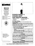
1
Owners
Manual
FOR POTABLE WATER
HEATING ONLY
NOT SUITABLE FOR
SPACEHEATING
NOT FOR USE IN
MOBILE HOMES
Model No.
153.337114
153.337163
153,337214
153.3379.63
153.337363
153.337414
153.337463
153.337514
153.337563
153.337614
153.337663
153.337763
153.337863
153.337962
50 Gal. Short High Altitude
S0 Gal. Short
40 Gal. Short High Altitude
40 GaL Short
POWER
MISERTM9
GAS
WATER
HEATER
30 Gal,
• Safety Instructions
40 Gal. High Altitude
40 Gal.
• Operation
• Care and Maintenance
• Troubleshooting
• Parts List
• Installation
50 Gal, High Akitude
50 Gal.
For Your Safety
65 Gal. High Altitude
65 Gal.
50 Gal. High Recovery
65 Gal. High Recovery
40 Gal. (L.R)
AN ODORANT
IS ADDED
WATER HEATER
TO THE GAS USED
BY THIS
WARNING: If the information in these instructions are not followed exactly, a fire or explosion may result, causing property
damage, personal injury or death.
-Do not store or use gasoline or other flammable vapors and liqrods in the vic'nity of this or any other appliance.
-WHAT TO DO IF YOU SMELL GAS
: Do not try to light any appliance.
Do not touch any electrical switch; do not use any phone in your
building.
i Immediately
Follow the gascall
supplier'slnstructions.
your gas supplier from,_.a neighbor's phone.
If you can not reach your gas supplier, call the fire department,
-Installation and service must be performed by a qualified installer,
service agency or the gas supplier.
Caution:
Read and Follow
All Safety Rules and
Improper
Operating Instructions
Before First Use of
installation,
•
AWARNING
adjustment,
alteration,
.
service or mamtenance
I.
I
can cause DEATH, SERIOUS BOD!LY INJURY, OR PROPERTY DAM- I
AGE: Refer to this manual for assistance or consult the local Sears I
Servtce Center or gas utility for further mformation.
I
This Product.
AWARNING
Flammable
vapors may be drawn
of the structure to this appliance.
Save this Manual for Future Reference.
Sears,
Roebuck
by air currents
from
other
areas
A, WARNING
READ THE GENERAL SAFETY SECTION BEGINNING ON INSIDE
COVER AND THEN THIS ENTIRE MANUAL BEFORE INSTALLING
OR OPERATING THIS WATER HEATER.
and Co., Hoffman
Estates,
IL 60179
U.S.A.
Safety Precautions
I
_WARNING
A WARNING
.
At the time of manufacture this water heater was previd-/
ed with a combination temperature-pressures relief valve
certified by a nationally recognized testing laboratory
that maintains periodic inspection of production of listed
equipment or materials, as meeting the requirements
for Relief Valves and Automatic Gas Shutoff Devices for
Hot Water Supply Systems, and the latest edition of
ANSI Z21.22 and the code requirements of ASME. If
replaced, the valve must meet the requirements of local
codes, but not lessthan a combination temperature and
pressure relief valve certified as meeting the requirements for Relief Valves and Automatic Gas Shutoff
Devices for Hot Water Supply Systems, ANSI Z21.22 by
a nationally recognized testing laboratory that maintains
periodic inspection of production of listed equipment or
materials.
The valve must be marked with a maximum set pressure
not to exceed the marked hydrostatic working pressure
of the water heater (150 Ibs./sq. in.) and a discharge
capacity not less than the water heater input rate as
shown on the model rating plate. (Electric heaters.
watts divided by 1000 x 3415 equal BTU/Hr. rate.)
Your local jurisdictional authority, while mandating the
use of a temperature-pressure relief valve complying
with ANSI Z21.22 and ASME, may require a valve model
different from the one fumnishedwith the water heater.
Compliance with such local requirements must be satisfied by the installer or end user of the water heater with
a locally prescribed temperature-pressure relief valve
installed in the designated opening in the water heater in
)lace of the factory furnished valve.
For safe operation of the water heater, the relief valve
must not be removed from it's designated opening or
plugged.
The temperature-pressure relief valve must be installed
directly into the fitting of the water heater designated
for the relief valve. Positionthe valve downward and provide tubing so that any dischargewill ex'_ only within 6
inches above, or at any distance below the structural
floor. Be certain that no contact is made with any live
electrical part. The dischargeopening must not be
blocked or reduced in size under any circumstances.
Excessivelength, over 30 feet, or use of more than four
elbows can cause restrlctionand
reduce the discharge
capacity of the valve.
•
No valve or other obstruction is to be placed between
the relief valve and the tank. Do not connect tubing
directly to discharge drain unlessa 6" air gap is provided.
To prevent bodily inlury, hazard to life, or property damage, the relief valve must be allowed to dischargewater
in quantities should circumstances demand. If the discharge pipe is not connected to a drain or other suitable
means, the water flow may cause property damage.
The Discharge Pipe:
• Must not be smaller in size than the outlet pipe size of
the valve, or have any reducing couplings or other
restrictions.
Must not be plugged or blocked.
Must be of material listed for hot water distribution.
Must be installed so as to allow complete drainage of
both the temperature-pressure rehef valve, and the
dischargepipe.
Must terminate at an adequate drain.
Must not have any valve between the relief valve and
tank.
Improper installation, adjustment, altev_tlon, service or
maintenance can cause DEATH, SERIOUS BODILY
INJURY, OR PROPERTY DAMAGE. Refer to this menuat for assistance or consult your local Sears Service
Center for further information.
AWARNING
WATER HEATERS EQUIPPED FOR ONE TYPE GAS
ONLY: This water heater is equipped for one type gas
only. Check the model rating plate near the gas control
valve for the correct gas, DO NOT USE THIS WATER
HEATER WITH ANY GAS OTHER THAN THE ONE
SHOWN ON THE MODEL RATING PLATE. Failure to
use the correct gas can causeproblems which can result in
DEATH, SERIOUS BODILY INJURY, OR PROPERTY
DAMAGE. If you have any questions or doubts consult
your gassupplieror local utility.
AW_!_tRNING
INSTALLATIONS IN AREAS WHERE FLAMMABLE LIQUIDS (VAPORS) ARE LIKELY TO BE PRESENT OR
STORED (GARAGES, STORAGE, AND UTILITY AREAS,
ETC), Flammable liquids (such as gasoline, solvents,
propane (LP) or butane, eta), all of which emit flammable
vapors, may be improperly stored or used in such areas.
The gaswater heater pilot light or main burner can ignite
such vapors. The resulting flashback and fire can cause
death or serious bums to anyone in the area, as well as
property damage.
If installation in such areas is your only option, then the
installation must be accomplishedin a way that the pilot
flame and main burner flame are elevated from the floor
at least 18 inches.While this may reduce the chances of
flammable vapors from a floor spill being Ignited, gasoline
and other flammable substancesshouldnever be sto_l or
used in the same room or area contain ng a gas water
heater or other open flame or spark producing appliance.
NOTE: Flammable vapors may be drawn by air currents
from other areasof the structure to the appliance.
AWARNING
If this water heater will be used in beauty shops, barber
shops, cleaning, establishments, or self-service laundries
with dry cleaning equipment, it is imperative that the
water heater or water heaters be installed so that combustlon and ventilation air be taken from outside these
areas. Refer to the "Facts to Consider About the
Location" section of this manual and also the latest edition of the National Fuel Gas Code, ANSI Z223.1, also
referred to as NFPA 54 for specificsprovided €oncemnin
air required.
AWARNING
A fire can start if combus_ble mate.rialssuch as clothing, I
I cleaningmaterials, or flammable liqmdsare placed againstI
I Ornext tO the water h_=ter"
I
2
Safety Precautions
_WARNING
_,WARNING
This water heater must not be installed directly on carpeting. Carpeting must be protected by a metal or wood
panel beneath the appliance extending beyond the full
width and depth of the appliance by at least 3 inches
(76.2mm) in any direction, or if the appliance is installed
in an alcove or closet, the entire floor must be covered b
the panel. Failure to heed this warning may result in
fire hazard.
A gas water heater cannot operate properly without the
correct amount of air for combustion. Do not install in a
confined area such a closet, unless you provide air as
Ishownin the "Facts to Consider About the Location" section. Never obstruct the flow of ventilation air. If you have
any doubts or questions at all, call your gas company.
Failure to provide the proper amount of combustion air
can result in a llro or explosion and can CAUSE DEATH,
SERIOUS BODILY INJURY,OR PROPERTY DAMAGE.
_,WARNING
A, WARNING
VENT DAMPERS - Any vent damper, whether it is operated thermally or otherwise must be removed if its use
inhibits proper drafting of the water heater.
IThermally Operated Vent Dampers: Gas-fired water
heaters having thermal efficiency in excess of 80% may
_reduce a relatively low flue gas temperature. Such tern- i
_eratures may not be high enough to properly open thermally operated vent dampers. This would causespillageof
flue gasesand may causecarbon monoxide poisoning.
Vent dampers must bear evidenceof certification as complying with the latest edition of American National
Standard ANSI Z21.68 (ANSI Z21.66 & 67, respectively,
cover electrically and mechanically actuated vent
dampers). Before installation of any vent damper, consult
your local Sears Service Center or the gas utility for further information.
HOTTER WATER CAN SCALD: Water heaters are
intended to produce hot water. Water heated to a temperature which,will satisfy clothes washing, dish washing,
and other sanmzing needs can scald and permanently
iniure you upon contact. Some people are more likely to
be permanently injured by hot water than others. These
include the elderly, children, the infirm, or physically/mentally handicapped.If anyoneusing hot water in your home
fits into one of these groups_t_rif there is a local code or
state law requiring a certain temperature water at the hot
water tap, then you must take specialprecautions.In addition to using the lowest possibletemperature setting that
satisfiesyour hot water needs, a means such as a mixing
valve, should be used at the hot water taps used by these
people or at the water heater. Mixing valvesare available
at plumbing supply or hardware stores. Follow manufacturers instructions for installation of the valves. Before
changingthe factory setting on the thermostat, read the
"Temperature Regulation" section in this manual.
AWARNING
• The applianceand its individualshutoffvalve must be disconnected from the gas supplypiping system during any
pressure testing of the gas system at test pressures in
excessof ½ pound per square inch(3.5kPa).
• The appliance must be isolated from the gas supply piping system by closingits individual manual shutoffvalve
during any pressure testing of the gas supply piping system at test pressures equal or less than % pound per
square inch(3.5kPa).
AWARNING
Soot build-up indicates a problem that requires €orrection before further use. Turn "OFF" gas to water heater
and leave "OFF" until repairs are made, because failure
to correct the cause of the sooting can result in a fire or
explosion causing DEATH, SERIOUS BODILY INJURY,
IOR PROPERTY DAMAGE.
AWARNING
AWARNING
Chemical vapor corrosion of the flue and vent system
may occur if air for combustion contains certain chemical
I vapors. Spray can propellants, cleaningsolvents,refrigerator and air conditioner refrigerants, swimming pool
chemicals, calcium and sodium chloride, waxes, bleach,
and processchemicals are typical compounds which are
potentially corrosive.
BEFORE LIGHTING [PROPANE (L.P.) GAS WATER
HEATERS]: Propane (L.R) gas is heavier than air. Should
there be a leak in the system, the gas will settle near the
ground. Basements, crawl spaces, skirted areas under
mobile homes (even when ventilated), closets and areas
below ground level will serve as pockets for the accumulation of this gas. Before attempting to light or relight the
water heater_ pilot or turning on a nearby electrical light
sw_tch,be absolutelysure there is no accumulated gas in
the area. Search for odor of gasby sniffingat ground level
in the vicinity of the appliance. If odor is detected, follow
stepsindicated at "For Your Safety" on the cover page of
this manualthen leave the premises.
.AWARNING
Ob.structed or deteriorated vent systems may present a
serioushealth risk or asphyxiation,
Safety Precautions continued on page 4.
3
Safety Precautions
A'WARNING
A, CAUTION
1
The water heater with draft hood installed must be preperly vented to a chimney which terminates outdoors.
Never operate the water heater unlessit is vented to the
outdoors and has adequate air supply to avoid risks of I
improper operation, explosionor asphyxiation,
l
WATER HEATERS EVENTUALLY LEAI_ Installation of
the water heater must be accomplished in such a manner
that if the tank or any connections should leak, the flow
of water will not causedamage to the structure. For this
reason, it is not advisableto install the water heater in an
attic or upper floor. When such locations cannot be
avoided, a suitable drain pan should he installed under
the water heater. Drain pans are available at your local
Sears store. Such a drain pan must be not greater than
1I/2 inchesdeep, have a minimum length and width of at
least 2 inchesgreater than the water heater dimensions
and must be piped to an adequate drain. The pan must
not restrict combustion air flow. Under no circumstances
is the manufacturer or Sears to be held liable for any
water damage in connectionwith this water heater.
AWARNING
Minimum clearancesbetween the water heater and combustibleconstruction are I" at the sidesand rear, 4" at the
front, and 6" from the vent pipe. Clearance from the top
of the jacket is 18" on most models. Note that a lesser
dimension may be allowed on some models. Refer to the
label on the water heater adjacentto the gascontrol valve
for all clearances.
A, WARNING
Do not use this appliance if any part of it hasbeen under
water. Immediately call a_ears Service Technician to
inspect the appliance and to replace the gas control or any
part of the burner systemwh ch hasbeen under water.
AWARNING
HYDROGEN GAS: Hydrogen gascan be produced in a hot
water system that has not been used for a long period of
time (generally two weeks or more). Hydrogen gas is
extremely flammable and explosive. To prevent the possibility of injury under these conditions, we recommend the
hot water faucet be opened for several minutes at the
kitchen sink before any electrical appliances which are
connected to the hot water system are used (such as a
dishwasher or washing machine). If hydrogen gas is present, there vnll probably be an unusualsound similar to air
escaping through the pipe as the hot water faucet is
opened. There must be no smoking or open flame near
the faucet at the time it is open.
AWARNING
INSULATING JACKETS: When installing' an external
water heater insulationjacket on a gaswater heater:
DO NOT cover the temperature.pressure relief wive.
DO NOT put insulation over any part of the top of the
gaswater heater.
DO NOT put insulationever the gascontrol valve or gas
control valve/burner cover, or any access areas to the
burner.
DO NOT let insulation around the gaswater heater to
get within 8 inches of the floor (air must get to the
burner).
DO NOT cover or remove operating instructions, and
safety related warning labelsand materials alT_ed to the
water heater.
! Failure to heed this will result in the possibilityof a fire or
explosion.
4
Table of Contents
Safety Precautions ..................................................................................................
2-4
Table of Contents ...................................................................................................
5
Customer Re.s_onsibilities ..........................................................................................
6
Product Specincations ................................................................................................
6
Materials and Basic Tools Needed ............................................................................................... 7
Materials Needed ......................................................................................................................................................................
Basic Tools ....................................................................................................................
:...........................................................
7
7
Installation Instructions .............................................................................................
8-16
Removing the Old Water Heater ...............................................................................................................................................
Facts to Consider About the Location .......................................................................................................................................
Combustion Air and Ventilation for Appliances in Unconfined Spaces ...................................................................................
Combustion Air and Ventilation for Appliances in Confined Spaces .......................................................................................
Water Piping ...........................................................................................................................................................................
Temperature-Pressure Relief Valve...........................................................................................................................................
Filling the Water Heater ..........................................................................................................................................................
Venting .............................. .................................................................................................................................................
Gas Piping .........................................................................................................................................................................
Installation Checklist ..............................................................................................................................................................
8
9
10
10
11
12
13
13-14
14-15
16
Operating Instructions ...............................................................................................
17-19
Fighting .............................................................................................................................................................................
Temperature Regulation ..........................................................................................................................................................
17-18
19
Service and Adjustment
......................................................................................................................
20-22
Tank (Sediment) Cleaning ......................................................................................................................................................
20
Venting System Inspection ......................................................................................................................................................
20
Burner Inspection ...................................................................................................................................................................
20
Burner Cleaning .....................................................................................................................................................................
20
L.P.Gas Control Valve & Burner Assembly Replacement Information ....................................................................................
21
Draining .................................................................................................................................................................................
21
Temperature-Pressure Relief Valve Operation ..........................................................................................................................
21
Drain Valve Washer Replacement ...........................................................................................................................................
22
Housekeeping .........................................................................................................................................................................
22
Service ....................................................................................................................................................................................
22
Troubleshooting Guide .........................................................................................
23-25
Start Up Conditions ...............................................................................................................................................................
Condensation ........................................................................................................................................................................
Smoke/Odor .........................................................................................................................................................................
Thermal Expansion ...............................................................................................................................................................
Strange Sounds ......................................................................................................................................................................
Operational Conditions ..........................................................................................................................................................
Smelly Water .........................................................................................................................................................................
Air in Hot Water Faucets ......................................................................................................................................................
23
23
23
23
23
24
24
24
High Temperature Shut OffSystem ......................................................................................................................................
Not Enough or No Hot Water ..............................................................................................................................................
Water is too Hot ...................................................................................................................................................................
Leakage Checkpoints ..............................................................................................................................................................
24
24
24
25
Parts Order List......................................................................................................
28-35
5
Customer
Thank
Responsibilities
You forporchasing
a Searswater heater.
This manual contains instructions for the installation, operation, and maintenance
of the gas-fired water heater. It also
contains warnings through out the manual that you must read
and be aware of. All warnings and all instructions are essential
to the proper operation of the water heater and your safety.
Since we cannot put everything on the first few pages, READ
THE ENTIRE
MANUAL BEFORE ATTEMPTING
TO
INSTALL OR OPERATE THE WATER HEATER.
• The installation must conform with the instructions in this
manual; gas company
rules; and Local Codes, or in the
absence of Local Codes, with the latest edition of the National
Fuel Gas code, ANSI Z223.1, also referred to as NFPA 54.
This publication
is available from your local government or
public
library
or gas company
or by writing
NFPA,
Batterymarch Park, Quincy, MA 02269.
• If after reading this manual_ou
have any questions or do not
understand
any portion otthe
instructions,
call the Sears
Service Center.
• Carefully plan the place where you are going to put the water
heater. Correct combustion, vent action, and vent pipe installation are very important in preventing death from possible
carbon monoxide poisoning and fires.
Examine the location to ensure the water heater complies with
the "Facts to Consider About the Location" section in this
Properly installed and maintained,
it should give you years of
trouble free service. If you should decide that you want the new
water heater professionally installed by Sears call the local Sears
Service Center or any Sears store. They will arrange for prompt,
quality installation by Sears authorized contractors.
Abbreviations
Found In This Instruction
Manual
CSA - Canadian Standards Association
ANSI - American National Standards Institute
NFPA - National Fire Prevention Association
AWARNING
This gas.firedwater heater isdesigncertified by CSA INTERNATIONAL under American National Standard/CSA
Standardfor GasWater HeatersANS Z2 I.I 0. I • CSA 4. I (latest edition). The installationmustconform with this manual,
Local Codesand with the latest editionof the National Fuel
GasCode, ANSI Z223.1.
This publicationis availablefrom your localgovernment or
public library, gas company, or by writing NFPA,
Batterymarch Park, Quincy,MA 02269.
manual.
•
•
Read the "Safety Precautions" section, pages 2 through 4 of
this manual first and then the entire manual carefully. If you
don't follow the safety rules, the water heater will not operate
properly.
It could cause DEATH,
SERIOUS
BODILY
INJURY AND/OR
PROPERTY DAMAGE.
•
For California installation this water heater must be braced,
anchored, or strapped to avoid falling or moving during an
earthquake.
See instructions
for correct installation
procedures. Instructions
may be obtained from your local dealer,
wholesaler, public utilities or California O_ce of the State
Architect, 400 P Street, Sacramento, CA 95814.
Complies with SCAQMD
rule #1121 and districts having
equivalent NOx requirements.
Product Specifications
RECOVERY
MODEL NUMBER
153.337114
TANK
CAPACITY
IN GALLONS
50
153.337163
50
153.337214
153.337263
153.337363
40
40
153.337414
30
40
153.337463
153.337514
40
153.337563
153.337614
50
153.337663
153.337763
153.337863
65
153.337962
50
65
50
65
40
TYPE
OF
GAS
NATURAL
NATURAL
NATURAL
NATURAL
NATURAL
NATURAL
NATURAL
NATURAL
NATURAL
NATURAL
NATURAL
NATURAL
NATURAL
PROPANE
B.ZU.
RATE
40,000
40,000
40,000
40,000
40,000
40,000
40,000
40,000
40,000
40,000
40,000
52,500
50,000
40,000
RATE GALS.
PER HOUR
@ 90°F RISE
40.9
40.9
40.9
40.9
40.9
40.9
40.9
40.9
40.9
40.9
40.9
53.7
51.2
40.9
MINIMUM
DIMENSIONS IN INCHES
VENT
DIAMETER
PIPE
Y'or
4"
3" or
3" or
3"or
Y' or
4"
4"
4",
4"
Y'or
4"
16"
18"
3"or 4"
3" or 4"
18"
20"
3"or
3"or
20"
4"
4"
22"
22"
20"
20"
4"
22"
22"
20"
22"
3" or 4"
18"
3" or 4"
4"
HEIGHT TO
JACKETTOP
49"
49"
47½"
4TA"
57½"
58¼"
58¼"
58"
58"
59_"
59_4"
58¾"
59½"
58'A"
Materials and Basic Tools Needed
Materials Needed
To simplify the installation Sears has available the installation
parts shown below. You may or may not need all of these materials, depending on your type of installation.
I
WATER HEATER STAND 24"x24"x 18"
FOR USE WITH WATER HEATERS
INSTALLED IN RESIDENTIAL
GARAGES HAVING A DIAMETER 24"
OR LESS AND A RATED CAPACITY 75
GALLONS OR LESS
WATER HEATER HEAT
TRAPS HELP REDUCE
HEAT LOSS DUE TO
THERMAL SYPHONING
@
VENT
ELBOW
EXPANSION
TANKS
FOR THERMAL
EXPANSION
CONDITIONS AVAILABLE IN
2 GALLON AND 5
GALLON CAPACITY
THROUGH
LOCAL
SEARS STORE OR
SERVICE CENTERS
WATER HEATER INSTALLATION KIT WITH FLEXIBLE CONNECTORS
FOR
3/4" OR I/2" THREADED
OR COPPER PLUMBING
VENT
FLEXIBLE WATER
HEATER GAS CONHECTOR WITH
FITTINGS
DRAIN PANS AVAILABLE IN 20"
DIAMETER FOR WATER HEATERS
HAVING A DIAMETER 18" OR LESS, 24"
DIAMETER FOR WATER HEATERS
HAVING A DIAMETER 22" OR LESS AND
AVAILABLE IN 28" DIAMETER FOR
WATER HEATERS HAVING A DIAMETER
26" OR LESS
PiPE
Basic Tools
ADDITIONAL
TOOLS
NEEDED
WHEN
SWEAT
SOLDERING
You may or may not need all of these tools, depending on your
type of installation. These tools can be purchased at your local
•
•
•
•
•
•
Scars store.
• Pipe Wrenches (2) 14"
• Screwdriver
• Tin Snips
• 6 Foot Tape of Folding Rule
• Garden
• Drill
• Pipe
Tubing Cutters or Hacksaw
Propane Torch
Soft Solder
Solder Flux
EmeryCIoth
Wire Brushes
Hose
dope
or Teflon
Tape
HACKSAW
GARDEN
HOSE
6 FOOT TAPE
SLOT-HEAD
PiPE
WRENCH
3/4" WIRE BRUSH
SCREVYDRIVER
I/2" WIRE BRUSH
PHILLIPS
SCREWDRIVER
PROPANE
I TORCH
ROLL OF LEAD FREE
SOFT SOLDER
8
ROLL OF TEFLON TAPE
(USE ONLY ON WATER
CONNECTIONS)
PiPE DOPE (SQUEEZE TUBE)
_FOR
WATER AND
CONNECTIONS)
ROLL OF EMERY
CLOTH
SOLDER
FLUX
TUBING
CUTTER
,
Installation
Removing
Instructions
the Old Water
Heater
Turn "OFF" the gas supply to the water heater.
Disconnect
the vent pipe from the draft hood where
they connect to the water heater. In most installations
the vent pipe can be lifred off after any screw or other
attached devices are removed.
Dispose of the draft
hood. The new water heater has the draft hood which
must be used for proper operation.
_WARNING
I If the main gas line--all
gas appliances is
I used, also shut "off" the gas at each appliance. Leave all
gasappliances shut "off" until the water heater installation
I iscomplete.
®
®
®
Turn "OFF"
the water 6o the water
heater. Some installations
require that
the water be turned off to the entire
a. If you have copper piping to the water
heater, the two copper water pipes can
be cut with a hacksaw approximately
four inches away from where they connect to the water heater. This will avoid
cutting
off the pipes
too short.
Additional cuts can be made later if necessary. Disconnect the temperature-pressure relief valve drain line. When the
water heater is drained, disconnect the
hose from the drain valve. Close the
drain valve. The water heater is now
completely disconnected and ready to be
removed,
house,
@
b. If you have galvanized pipe to the water
heater, loosen the two galvanized pipes
with a pipe wrench at the union in each
line. Also disconnect the piping remaining to the water heater. These pieces
should be saved since they may be needed when reconnecting the new water
heater. Disconnect the temperature-pressure relieftvalve drain line. When the
water heater is drained, disconnect the
hose from the drain valve. Close the
drain valve. The water heater is now
completely disconnected and ready to be
removed.
Check again to nlRke sure the gas supply
is OFF" to the water heater. Then disconnect the gas supply connection from
the gas control valve.
Attach
valve
drain
drain
faucet
water
I
a hose to the water
heater drain
and put the other end in a floor
or outdoors. Open the water heater
valve. Open a nearby hot water
which will relieve pressure in the
heater and speed draining.
_,WARNING
I
The water passing out of the drain valve may be ,e._remely I
hot. To avoid being sr._ded, make sure all connections are I
tight and that the water flow is directed away from any I
&CAUTION
I
Mineral buildupor sediment may haveaccumulated in the ]
old .water heater, This causesthe water heater to be much
heavier than normal and this residue, ff spilled out, could
person.
causestain ng.
I
Installation
Instructions
Facts to Consider About
Location
You should carefully
water heater, because
eration for the safety
the most economical
not for use in mobile
(cont'd)
the
• The location selection must provide adequate clearances for servicing and proper operation of the waterheater.
choose an indoor location for the new
the placement is a very important considof the occupants in the building and for
use of the appliance. This water heater is
homes or outdoor installation.
AWARNING
Thiswater heater mustnot be installeddirtily on carpeting.
ICarpeting must be protected by a metal or wood panel
beneath the applianceextendingbeyondthe full width and
depth of the appliance by at least 3 nches(76 2ram) n any
!dlrectJon,or if the applianceis installedin an alcoveor closet,
the entirefloor mustbe coveredby the panel.Failureto heed
this warningmayresultin a Erehazard.
Whether
replacing an old water heater or putting
the water
heater in a hew location, the following critical points must be
observed.
The location selected should be indoors as close as practical
to the gas vent or chimney to which the water heater vent is
going to be connected, and as centralized with the water piping system as possible. The water heater, as all water heaters,
will eventually
leak. Do not install without
adequate
drainage provisions where water flow will cause damage.
AWARNING
Minimum clearancesbetween the water heater and €ombustibleconstructionare I" at the sidesand rear, 4" at the
front, and 6"from the ventpipe.Clearancefrom the top of the
jacketis 18"on most modeK Note that a lesserdimensionmay
be allowedon somemodels. Refer to the label on the water
heateradjacentto the gascontrolvalvefor all dearances.
ACAUTION
WATER HEATERS EVENTUALLY LEAK: Installationof the
water heater must be accom011shecl
in sucha manner that if
the tank or anyconnectionsshouldleak,the Bowof water will
not causedamageto the structure..Forthis reason,it is not
advisableto instailthe water heater m an attic or upper floor,i
When suchlocationscannotbe avoided,a suitabledrain pan
shouldbe installed under the water heater. Drain pansare
availableat your localSearsstore. Sucha drain pan must be
not greater than I% inchesdeep,havea minimum lengthand
widthof at least2 inchesgreaterthan the water heater dimensionsand must be pipedto an adequatedrain.The pan must
mt restrictcombustion air flow.Under no circumstances
isthe
nanufactureror Searsto be heldliablefor anywater damage
n connectionwith this water heater.
ZI" t'_N.
VENTILATION
OPENINGS
4'MIN.
"_N,
[
AWARNING
INSTALLATIONSIN AREASWHERE FLAMMABLELIQUIDS
VAPORS) ARE LIKELY TO BE PRESENT OR STORED
(GARAGES, STORAGE, AND UTILITY AREAS, ETC):
Flammableliquids(such as gasoline,solvents,pmpene(LP) or
butane, etc.), all of which emit flammable vapors, may be
improperlystored or usedin such area_ The gaswater heater
pilot lightor main burnercanignitesuchvapor_The resulting
flashbackandfire cancausedeath or serious bumsto anyonein
the area,aswellaspropertydamage.
If installationin suchareasis youronlyoption,then the installation must be accomplished in a way that the pilot flame and
!mainburnerflameare elevatedfrom the floorat least 18inche_
Y/hUe thk may reducethe chancesof flammablevaporsfrom a
floorspillbeing ignited,gasolineandotherflammablesubstances
shouldneverbe storedor usedin the same room or area contalninga gaswater heateror other openflameor sparkproducingappliance.
NOTE: Flammablevaporsmay be drawnby air currentsfrom
other areasof the structureto the appliance.
1
AWARNING
A gaswater heater cannotoperate properlywithout the correct amountof air for combustion.Do not installin a confined
area such a closet,unlessyou provideair as shownin Figures
I-5. Never obstructthe flaw of Cen_lationair. If you haveany
doubtsor questionsat all,callyour gascompany.Failureto providethe properamount of combust_nair canresultin a fire or
explosionand can causeDEATH, SERIOUS BODILY INJUR_,
OR PROPERTYDAMAGE.
AWARNING
If this water beater will be usedin beautyshops,barbershops,
cleaningestablishments,or self.service laundries with dry
cleaningequipment,it is imperativethat the water heater or
water heatersbe installedsothat €ombustlenand ventlindon
air be taken from outsidethese areas.Refer to the "Facts to
ConsiderAbout the Location"socden of this manualand also
the latestedition of the NationalFuelGas Code,ANSI Z223..I,
also re_n'ad to as NFPA 54 for specificsprovidedconcerning
air required.
AWARNING
Pmpellaotsof aemsel spraysand volatile compounds,.(cleaners,chlorinebasedchemicais,refrigerants,etc.) in additionto
beinghighlyflammable In many cases,will a/sochangeto €orro_vo hydrochloricacid when exposed to the combustion
productsof the water .I.."......_...
The resultscan be hazardous,
andalsocauseproductfailure.
9
Installation
Instructions
(cont'd)
Combustion Air and Ventilation
for Appliances Located in
Unconfined Spaces
Unconfined Space is a space whose volume is not less than 50
cubic feet per 1,000 Btu per hour of the aggregate input rating
of all appliances installed in that space. Rooms communicating
directly with the space in which the appliances are installed,
through openings not furnished with doors, are considered a
part of the unconfined space
In unconfined spaces in buildings, infiltration may be adequate
to provide air for combustion, ventilation and dilution of flue
gases. However, in buildings of tight construction (for example,
weather stripping, heavily insulated, caulked, vapor barrier, etc.),
additional air may need to be provided using the methods
described in Combustion Air and Ventilation for Appliances
Located in Confined Spaces, b.
1. When directly communicating with the outdoors, each opening shall have a minimum free area of 1 square inch per 4,000
BTU per hour of total input rating of all equipment in the
endusure. (See Figure 3.)
2. When communicating with the outdoors through vertical
ducts, each opening shall have a minimum free area of 1
square inch per 4,000 BTU per hour of total input rating of
all equipment'in the enclosure. (See Figure 4.)
_4_qEY
OR OA8 gZhT
Combustion Air and Ventilation
for Appliances Located in
Confined Spaces
Con.rmed Space is a space whose volume is less than 50 cubic
feet per 1,000 Btu per hour off,the aggregate input rating of all
appliances installed in that space.
a. ALL AIR FROM INSIDE BUILDINGS:
(See Page 9 Figure 1, and Figure 2 below)
The confined space shall be provided with two permanent
openings communicating directly with an additional room(s)
oF suff*lcient volume so that the combined volume of all
spaces meets the criteria for an unconfined space. The total
input of all gas utilization equipment installed in the combined space shall be considered in making this determination.
Each opening shall have a minimum free area of one square
inch per 1,000 BTU per hour of the total input rating ofail
gas utilization equipment in the confined space, but not less
than 100 square inches. One opening shall commence within
12 inches of the top and one commencing within 12 inches
of the bottom of the enclosure.
Figure 4 ]
3. When communicating with the outdoors through horizontal
ducts, each opening shall have a minimum free area of 1
square inch per 2,000 BTU per hour of total input rating of
all equipment in the enclosure. (See Figure 5.)
Figure 5 1
_SRT
4. When ducts are used, they sha_ be of the same cruss-sectlonal
area as the free area of the openings to which they connect.
The minimum short side dimension of rectangular air ducts
shall not be less than 3 inches. (See Figure5.)
Figure 2 ]
[
[
,
....
b. ALL AIR FROM OUTDOORS:
(see Figures 3-5)
The confined space shall be provided with two permanent
openings, one commencing within 12 inches of the top and
one commencing within 12 inches from the bottom of the
enclosure. The openings shall communicate directly, or by
ducts, with the outdoors or spaces (crawl or attic) that freely
communicate with the outdoors.
Louvers and Grilles: In calculating free area, consideration
shall be given to the blocking effect of louvers, grilles or
screens protecting openings. Screens used shall not be smaller
than ¼ inch mesh. If the free area through a design of louver
or grille is known, it should be used in calculating the size
opening required to provide the free area specified. If the
design and free area is not known, it may be assumed that
wood louvers will be 20-25 percent free areaand metal louvers
and grilles will have 60-75 percent free area. Louvers and
grilles shall be fixed in the open position or interlocked with
the equipment so that they are opened automatically during
equipment operation.
.
.
Figure 3 ]
10
Special Conditions Created by Mechanical Exhausting or
Fireplaces: Operation of exhaust fans, ventilation systems,
clothes dryers or firephcea may create conditions requiring
special attention to avoid unsatisfactory operation of ii_talled
gas utilization equipment.
Installation
Water
Instructions
(cont'd)
Piping
AWARNING
Look at the top cover of the water heater. The cold water
inlet is marked cold. Put two or three turns of" teflon tape
around the threaded end of _e threaded-to-sweat
coupling
and around both ends of the ¾ threaded nipple. Using flexible connectors, connect the cold water pipe to the coldwater
inlet of the water heater.
HOTTER WATER CAN SCALD:.Water heatersare intendedto
producehot water.Water heatedto a temperature .whichwill
saUsfyclotheswashing,dishwashing,and othersanitizingneeds;
canscaldand permanentlyinjureyou uponcontact.SomepeoPole
are more likelyto be permanentlyinjuredbyhot water than
rs. Theseincludetheelder_,children,the infirm,or physical.
ly/mentally handicapped.
If anyoneusinghotwater in your home
fitsintoone ofthese groupsor if there isa localcodeor statelaw
requiring a certaintemperaturewater at the hot w_er taR then
you must take specialprecautions.
In additionto usingthe lowest
possib/etemperaturesettingthat satisfies
your hot water needs,
a meanssuchasa mixingvalve,shouldbe usedat the hot water
tapsusedby these peopleor at the water heater.Mixingvalves
areavailableat plumbingsupplyor hardwarestores.Followmanufacturers instructionsfor installationof the valves. Before
changing the factory setting on the thermostat, read the
"Temperature Regulation"sectionin this manual.
NOTE: This water heater is super insulated to minimize
heat loss from the tank. Further reduction in heat loss
can be accomplished by insulating the hot water lines
from the water heater.
INSTALLATION
COMPLETED USING
SEARS INSTALLATION
KIT
FLEXIBLE
WATER
CONNECTORS
This water heater shall not be #onnected to any heating systems
or component(s)
used with a non-potable
water heating
appliance.
SHUTOFF
VALVE
HOT OUTLET
If a water heater is installed in a closed water supply system;
such as one having a back-flow preventer, check valve, water
meter with a check valve, etc.., in the cold water supply; means
shall be provided to control thermal expansion.
Contact
the
local utility or local Sears Service Center on how to control this
situation.
COLD, ;
WATER
TO HOUSE
/
THREADED TO
SWEAT COUPLING
THREADED TO
SWEAT COUPLING
3/4" THREADED
COUPLING
3/4" THREADED
COUPLING
NOTE: Toprotect against untimely corrosion of hot and
cold water fittings, it is stronl_ly recommended that di-electric untons or couplings be mstalled on this water heater
when connected to copper pipe.
LINE
The illustration shows the attachment of the water piping to the
water heater. The water heater is equipped with ¾ inch water
connections.
PRESSURE
RELIEF VALVE
NOTE: If using copper tubing, solder tubing to an adapter
before attaching the adapter to the cold w,.ater'.mlet connection. Do not solder the cold water supply llne directly to the
cold water inlet. It will harm the dip tube and damage the
tank.
•
[]
Look at the top cover of the water heater. The water outlet is
marked hot. Put two or three turns of teflon tape around the
threaded end of the threaded-to-sweat
coupling and around
both ends of the ¾" threaded nipple. Using flexible connectors, connect the hot water pipe to the hot water outlet on
the water heater.
DISCHARGE
PIPE (Do not cap
or plug)
6" AIR GAP
FLOOR DRAIN
11
Installation
Instructions
Temperature-Pressure
(cont'd)
Relief Valve
a, WARNING
AWARNING
The temperature-pressure relief valve must be manuall:
operated at least once a year Caution shouldbe taken tt
! ensurethat (I) no one is in front of or aroundthe outlet o
the temperature-pressurerelief vaJvedischargeline, and (2)
the water manually dischargedwill not cause any bodily
injury or property damage because the water may be
extremely hot.
At the time of manufacturethis water heater was provided
with a combinationtemperature-pressures
reliefvalvecertified
by a nationally recognizedtesting laboratory that maintains
periodicinspectionof productionof listedequipmentor materials, as meeting the requirements for Relief Valves and
_utomatic GasShutoffDevicesfor Hot Water SupplySystems,
md the latest edition of ANSI Z21.22 and the code require.
_ents of ASME. If replaced, the valvemust meet the require_ents of localcodes,but not lessthan a combinationtemperapureand pressurerelief valvecertifiedas meetingthe requirementsfor ReliefValvesand Automatic GasShutoffDevicesfor
Hot Water SupplySystems,ANSI Z21.22 bya nationallyrecognizedtestinglaboratory that maintains periodic inspectionof
pTreduction
of listedequipmentor materials.
he valvemust be marked with a maximum set pressurenot
to exceed the marked hydrostaticworking pressureof the
water heater (150 Ibsdsq,in.) and a dischargecapacitynot less
thanthe water heater input rate as shown on the modelrating
plate. (Electric heaters- watts dividedby 1000x 3415 equal
BTU/Hr. rate.)
.
Yourlocaljurisdictionalauthor_y,while mandatingthe useof a
temperature-pressure
relief valvecomplyingwith ANSI Z21.22
and ASME, may require a valvemodel differentfrom the one
furnishedwith the water heater.
Compliancewith suchlocalrequirementsmust be satisfiedby
the installeror end userof the water heater with a locallyp,rescribed temperature-pressurerelief valveinstalledin the designated openingin the water heater in placeof the factory fur.
nishedvalve,
Forsafeoperationof the water heater,the relief valvemustnot
beremoved from it_ designatedopeningor plugged,
.Thetemperature-pressure
relief valvemustbe installeddirectly
intothe fittingofthe water heaterdesignated
for the raliefvalve.
)ositionthe valvedownwardandprovidetubingsothat anydischargewill exit onlywithin 6 inchesabove, or at any distance
)elow the structuralfloor.Be certainthat no contact is made
with any liveelectricalpart.The dischargeopeningmust not be
blockedor reduced in size underany circumstances.
Excessive
leng_, over 30 feet, or useof more than fourelbowscancause
restriction and reducethe discharge
capacityofthe valve.
qo valveor other obstructionis to be placedbetweenthe relief
ralveand the tank. Do not connecttubingdirectlyto discharge
Iraln unlessa 6" air gapisprovided,
To preventbodilyinjury,haz,'d to life,or propertydamage,the relief valvemustbe allowed
to discharge
water in quantitiesshouldcircumstances
demand.If
the discharge
pipeis not connectedto a drain or other suitable
means,the water flowmaycausepropertydamage.
• e DischargePipe:
Must not be smallerin sizethan the outlet pipesize of the
valve,or haveany reducingcouplings
or other restrictions.
Mustnot be pluggedor Mocked.
Mustbe of materiallistedfor hot water distribution.
Must be installedso as to allow completedrainageof beth
the temperature-pressure relief valve, and the discharge
pipe.
Mustterminate at an adequatedrain,
Must not haveanyvalvebetween the relief valveand tank.
If after manual.lyoperating the valve, it fails,to completely
reset and continuesto release water, immediately closethe
cold water inlet to the water heater, follow the draining
instructions, and replace the temperature-pressure relief
valvewith a new one.
HOT
SHUTOFF
VALVE
COLD
PRESSURE
RELIEF VALVE
(Do not cap or plug)
[]
6" AIR GAP
RELIEFVALVEOPENING
At the time of manufacture,
this water heaterwasprovidedwitha combination
temperature-pressure
relief wive listedascomplying
withthe standard
forrelief_lves and
automaticgasshut-offdevicesfor hot water supplysystems,
ANSI Z2L22. For safe
operationof the v_ter heater,thereliefvalvemu_ not be removedfromitsdesignated
pointof installation
or plu/ged.
YourIota;jurisdictional
authority,whilemandating
the useof a temperature-pressure
relief valvecomplying
withANSi7-21.22andASHE,mayrequirea valvemodeldifferent
fromthe onefurnished
withthe waterheater
Compliance
withsuchlocal_luirements must besatisfied
by theinstaller
or enduser
of the waterheaterwitha locallyprescribed
temperature-pressure
reliefvalveinstalled
inthe designated
openingin thewaterheater.
Seemanualheading
-'°Temperature.Pressure
ReliefValves"
for installation
andmaintenanceofrelief valve,discharge
line,andothersefe_precautions.
]2
Installation
Filling the Water
Instructions
(cont'd)
Heater
ACAUT,ON
I
For proper venting in certain installations, a larger diameter vent
pipe may be necessary. Due to great variances in installations,
unforeseeable by the manufacturer of the water heater, you must
consult your gas company to aid you in determining the proper
venting for your water heater from the vent tables in the latest edition of the National Fuel Gas Code ANSI Z223.1, also referred to
as NFPA 54.
Never usethis water heater unlessit is completelyfilled with
.w_e.r.To preventdamageto the tank, the tank must be filled
with water.. Water must flow from the hot water faucet
beforeturning"ON gasto the water heater.
To fill the water heater with water:
• Close the water heater drain valve by turning the handle to
the right (clockwise). The drain valve is on the lower front of
the water heater.
• Open the cold water supply valve to the water heater.
NOTE: The cold water supply valve must be left open
when the water heater is in use.
• To insure complete filling of the tank, allow air to exit by
opening the nearest hot water faucet. Allow water to run
until a constant flow is obtained. This will let air out of the
water heater and the piping.
• Check all new water piping for leaks. Repairas needed.
Check the venting system for signs of obstruction or deterioration
and replace if needed.
The combustion and ventilation airflow must not be obstructed.
AWARNING
I
Obstructed or deteriorated vent systemsmay presenta serious
healthrisk or asphyxiation.
• Place the draft hood legs in the receiving holes on the top of
the water heater. The legs will snap in the holes to give a tight
fit.
• Place the vent pipe over the draft hood. With the vent pipe in
position, drill a small hole through both the vent pipeand
draft hood. Secure them together with a sheet metal screw,
Venting
AWARNING
VENT DAMPERS - Any vent damper,whether it is.operated
thermallyor otherwisemustberemovedif itsuseinhtbits proper draftingofthe water heater.
.Tl_.rmallyOperated Vent Dampers:Gas-firedwater heaters
Imvingthermal efEciencyin e_cessof 80%may producea relaffvdy lowflue gastemperature. Suchtemperaturesmay not be
high enough to properly open thermally operated vent
damper_ Thiswouldcausespillageof flue gasesand may cause
carbonmon_ide poisoning.
Vent dampersmust bear evidenceof certillcation ascomplying
with the latest edition of American National StandardANSI
7.21.68(ANSI Z21.66 & 67, respectively,
coverelectricallyand
mechanically
actuatedventdampers).Beforeinstallationof any
ventdamper,consultyourlocalSearsServiceCenter or thegas
u_ity for further information.
DRAFT
HOOD
,0
t
_VENT'x_
*_==k
DRAFT
_CREW_J
HO_
I _
- DRAFT
HOOD
TNTOOUTDOORS
OR
_,WARNING
The water heater with draft hoocl,installedmust be pmperb/
I vented to a chimney which.terminatesoutdoor_ Never oper-I
ate the water heaterunlessit isventedto the outdoorsand hasI
I adequateair _
to avoidrisksbf.impmperoperation,expIoI don or asphyxiation.
AWARNING
To insure proper venting of this gas-firedwater heater, the
correct vent pipediameter must be utilized.Any additionsor
deletionsof other gasapplianceson a commonvent with this
water heater may adverselyaffectthe operation of the water
heater.Consultthe localSearsServiceCenter or gasutility if
anysuchchangesare planned.
I
AWARNING
1
The vent pipefrom the water heater must be no lessthan the/
diameter of the draft hood outlet on the water heatertand|
_x_
13
slopeupward to the chimneyat least ¼ inchper
I,n /
Installation
Instructions
Venting (cont'd)
(cont'd)
Gas Piping
All vent gases must be completely vented to the outdoors of the
structure (dwelling). Installonly the draft hood provided with
the new water heater and no other draf_ hood.
Vent pipes must be secured at each joint with sheet metal screws.
AWARNING
Make sure the gas supplied is the same type listed on the
model rating plate. The inlet gas pressuremust not exceed
10.5in.water column(2.6kPa) for natural gasor 13 in.water
column (3.2kPa) for propane(I-R) gas.The minimum inlet
gas pressurelisted on the model rating plate is for the pur.
poseof input adjustment.
TO
CHIMNEY
RISE PER LINEAR
FOOT
!
•
AWARNING
I
If the gascontrolvalveis subjectedto pressuresexceeding_AI
pound per squareinch(3.5kPa), the damage to the gascontro valvecouldresult n a Ereor exploson from eakinggas.
VENT PIPE INSTALLATION
There must be a minimum of 6" clearance between single wall
vent pipe and any combustible material. Fill and seal any clearance between single wall vent pipe and combustible material
with mortar mix, cement, or other noncombustible substance.
For other than single wall, follow vent pipe manufacturer's clearance specifications. To insure _"tight fit of the vent pipe in a
brick chimney, seal around the vent pipe with mortar mix
cement.
AWARNING
[
If the main gasline shutoffserving all gasappliancesis used,[
also torn "off" the gasat each appliance.Leaveall gasappliancesshutoff until the water heater installations comp ete.
A gas line of sufficient size must be run to the water heater.
Consult the latest edition of National Fuel Gas Code ANSI
Z223.1, also referred to as NFPA 54 and the gas company concerning pipe size.
AWARNING
Failureto haverequired clearancesbetween vent pipingand
combustiblematerial will result in a Erehazard.
There must be:
• A readily accessiblemanual shut off valve in the gas supply line
serving the water heater, and
• A drip leg (sediment trap) ahead of the gas control valve to hdp
prevent dirt and foreign materials from entering the gas control
•
AWARNING
Be surevent pipeisproperly connectedto preventescapeof
dangerousilue gaseswh chcou d causedeadlyasphyxation.
valve,
• A flexible gas connector or a ground joint union between the
shutoffvalve and control valve to permit servicing of the unit.
Be sure to check all the gas piping for leaks before lighting the
water heater. Use a soapy water solution, not a match or open
flame. Rinse offsoapy solution and wipe dry.
AWARNING
t
Chemical vapor corrosionof the flue and vent system may
occurif air for combustioncontainscertain chemicalvapors.
Spraycan propellants,cleaningsolvents,refrigerator and air
conditionerrefrigerants, swimming pool chemicals,calcium
and sodiumchloride,waxes,bleach,and processchemicalsare
typicalcompoundswhichare potentiallycorrosive.
.
Standard Models are for installation up to 3,300 feet above sea
level.
High Altitude Models are for installation from 3,300 to 5,500
feet above sea level.
Ifa standard model is installed above 3,300 feet or a high altitude
model is installed above 5,500 feet, the input rating must be
reduced at the rate of 4 percent for each 1,000 feet above sea level.
Contact your local Sears Service Center or gas utility for further
information.
AWARNING
The appliance and its gas connection must be leak tested
before p acingthe app ance n operation.
14
Installation
Instructions
(cont'd)
GAS PIPING WITH
FLEXIBLE CONNECTOR
A WARNING
• The applianceand its individualshutoffvalvemustbe disconnectedfrom the gassupplypipingsystemduringanypressure
testing of the gassystem at test pressuresin excessof
poundper squareinch(3.SkPa).
• The appliancemustbe isolatedfrom the gassupplypipingsystem by dosingits individualmanualshutoffvalveduringany
pressuretestingof the gassupplypipingsystemat test pressuresequalor lessthan '/; poundper square inch(3.5k1_).
GS,_JND IOINT
U NlON(Opti°n_l)
_
CO_EO
at WARNING
[
Use pipe joint compound or teflon tape marked as being [
resistantto the actionof petroleum [Propene (I.R)] gase_ I
SEDIMENT
L
CAP
TRAP
GAS PIPING WITH ALL BLACK
PIPE TO GAS CONTROL
A sediment trap shall be installed as dose to the inlet of the
water heater as practical at the _me of water heater installation.
The sediment trap shall be either a tee fitting with a capped nipple in the bottom outlet or other device recognized as an effective sediment trap. If a tee fitting is used, it shall be installed in
conformance with one of the methods of installation shown
below.
GROUND JOINT _
UNlON(Opdonll)
IRON
BLACK PIPE
__
/
Connecting the gas piping to the gas control valve of the water
heater can be accomplished by either of the two methods shown.
CONTvALvEROL
3"
_,WARNING
m_
Contaminantsin the gaslinesmay causeimproper ope_
of the gas comrol valvethat may result in fire or explesion.
Beforeattachingthe gasline be surethat all gaspipe isclean
on the inside,To trap any dirt or foreign material in the gas
supply line, a drip leg (sometimes called a sediment trap)
must be incorporated in the piping. The drip leg must be
readilyaccessible.Installin accordancewith the "Gas Piping"
section.Refer to the latest edition of the National Fuel Gas
JCode, ANSI Z223.1, alsoreferredto asNFPA 54.
GAS
t,_
15
CAP
Installation
Instructions
(cont'd)
Installation Checklist
BEFORE LIGHTING
THE PILOT:
• Check the gas lines for leaks.
a. Use a soapy water solution. DO NOT test for gas leaks
usinga match or open flame.
b. Brush the soapy water solution on all gas pipes, joints and
fittings.
c. Check for bubbling soap. This means you have a leak.
Turn "OFF" gas andmake the necessary repairs.
d. Recheck for leaks.
e. Rinse offsoapy solution and wipe dry.
•
VENT PIPE TO
OUTDOORS
OR CHIMNEY
Is the new temperature-pressure
relief valve properly installed
and piped to an adequate dram. See Temperature-Preasure
UNION
SHUTOFF
HOT
COLD
Relief Valve" section.
• Are the cold and hot water lines connected to the water
heater correctly? See "Water Piping" instructions in the
"Installation Instructions" section.
DRAFT
HOOD
• Is the water heatercompletely filled with water? See "Filling"
instructions in the Installation Instructions" section.
• Will a water leak damage anything?
Consider About the Location" section.
VALVE
PRESSURE
RELIEF VALVE
See the "Facts to
DISCHARGE PIPE
(Do not cap or plug)
GAS SUPPLY
• Is there proper dearanee between the water heater and anything that might catch fire? See the "Facts to Consider About
the Location" section.
SHUTOFF
VALVE
• Do you have adequate ventilation so that the water heater
will operate properly? See "Combustion Air and Ventilation"
in the Facts to Consider About the Location" section.
TEE
• Is the draft hood vent piping properly secured? See "Venting"
instructions in the "Installation Instructions" section.
DRIP LEG
(Sediment
trap) PIPE CAP
• Is there proper clearance betwe,en the vent pipe and anything
that might catch on fire? See Venting instructions in the
"Installation Instructions" section.
6" AIR
DRAIN
VALVE
FLOOR
DRAIN
• Is the vent pipe properly sloped and does the vent terminate
,
. .
.
.
.
outdoors. See _ Venting
instructions
m the ¢¢Installation
Instructions" section.
• Do you need to call your gas company to check the gas pipe
and its hookup?
_TOVATE
UO_EL
NUMBER
!
Wllm
_llm"
_
ANS Z21_10
P0R
_
FIEGO_Y
I
BTm4R
Is0
pJkJ.....
_
I
]
I
.
]
.
]
MODEL RATING PLATE
16
.o
GAP
Operating
Instructions
Lighting
_WARNING
BEFORE LIGHTING [PROPANE (L.P,) GAS WATER
HEATERS]:Propane(L.P.)gasis heavierthan air. Shouldthere
be a leak in the system,the gaswill settle near the ground.
Basements,crawl spaces,skirted areasunder mobile homes
(evenwhenventilated),closetsandareasbelowgroundlevelwill
serve as pockets for the accumulation of this gas. Before
attemptingto light or relightthe water heater'spilotor turning
on a nearby electricallightswitch,be absolutely
sure there isno
accumulatedgasin the area. Searchfor odor ofgasbysniffingat
groundlevelin the vicinityof the appliance.If odor isdetected,
followstepsindicatedat "For YourSafety"on the coverpageof
fiismanual thenleavethe premises.
Figure 6 ]
Lighting and operating instructions are located on front of the
water heater, above or to one side of the gas control valve.
AW_RNING
AN ODORANT IS ADDED TO THE GAS USED
BY THIS WATER HEATER.
FOR YOUR SAFETY
IF YOU SMELLGAS:
Do not try to light anyappliance.
Do not touch any electricalswitch;do not useany phone in
your building.
Immediately callyour gassupplierfrom a neighbor'sphone.
Followthe gassuppliersinstructions,
If you cannot reach your gassupplier,call the Ere departmerit.
Figure 7 ]
a, WARNING
DO NOT force the gascontrol knob. Use only your hand to
pushit down to light the pilot, or to turn it to "ON", "OFF"
or "PILOT". Never usea tool suchas a lever,wrench or plio
ers, Do not hit or damage the knob. A damaged knob may
result in an explosionand serious injury. If you haveproblem
turning the knob, callthe gassupplierimmediately,
CHECK
FOR LEAKS
Be sure to check all your gas pipes for leaks before lighting your
water heater. Use a soapy water solution, not a match or open
flame. Check the factory gas ,fittings after pilot is lit and gas control knob is still in PILOT position. Then, check the fittings
when the main burner is turned "ON". Use a soapy water solution for this, too.
_INNER
DOOR
OUTER
DOOR
Figure 9 ]
17
Operating
Instructions
Lighting
label on the water
FOR YOUR
SAFETY
(cont'd)
heater as it appears above the thermostat
READ
BEFORE
LIGHTING
WARNING
If you do not follow these instructions exactly, a fire or explosion
may result causing property damage, personal injury or loss of life.
A. This appliance has s pilot which must be lighted by
hand.Whenlightingthe pilot,followtheseinstructions
exactly.
B. BEFORELIGHTINGsmellall aroundthe applianceares
for gas. Be sure to smell next to the floor because
somegasis heavierthanair and willsettleon thefloor.
WHATTO DOIF YOUSMELLGAS
• Do nottry to lightanyappliance.
• Do not touch any electric switch; do not use any
phonein yourbuildin9.
• Immediatelycall yourgas supplierfrom s neighbor's
phone.Followthegassupplier'sinstructions.
LIGHTING
• If you cannotreach your gas supplier,call the fir=
department.
C. Useonly yourhandto pushin or turnthe gas contro
knob.Neveruse tools. If the knobwill not pushin or
turn by hand,don'ttry to repairit, call s qualifiedservice technician."Forceor attemptedrepair may result
in a fire or explosion.
O. Do not use this applianceif any part has been under
water.Immediatelycall a qualifiedservicetechnician
to inspecttheapplianceandto replaceanypartof the
controlsystemand any gas controlwhichhas been
underwater.
INSTRUCTIONS
1. STOPtReadthesafetyinformationaboveon thislabel.
2. Removeouterdoor.I"
3. Set the thermostat to lowest settinq,by turning the
watertemperaturedial clockwise,(( _,) to its lowest
temperaturesetting(with arrowon dial)as shown.DO
9. Push in control knob all the way and hold down.
Immediatelylight the pilot with s match.Continueto
hold control knob in for about one (1) minuteafter
the pilot is lit. Releaseknoband it will pop backup.
Pilot shouldremainlit. If it goes out, repeatsteps3
through8.
e If knobdoes not pop up when released,stop and
immediatelycall your service technicianor gas
supplier.
• If the pilot will not stay lit after several tries,
depressandturn the gas controlknobclockwise
NOT FORCE,
4. Turngas controlknobclockwise_'_
to "OFF"position. Knob cannot be turned from "PILOT" to "OFF"
unlessknob is depressedslightly.DO NOT FORCE.
(Figure6, page 17)
5. Wait five (5) minutesto clear out any gas. If you then
smell gas, STOP!Follow"B" in the safety information
above on this label. If you don't smell gas, go to the
nextstep.
6. Remove(or open) inner door located belowthe gas
_ to "OFF" and callyourservicetechnician
or gassupplier.(Figure6, page17)
10. Replace(or close) innerdoor. Replaceouterdoor if
door does not covergas controlon/offknob or temperatureadjustmentknob.(Figure9, page17)
11. At armslengthaway,turn gascontrolknobcounterclockwise_
to the full "ON" position.Warning
do not use gas control knob to regulate gas
flow. (Figure8, page17)
12. At arms length away,set the thermostatto desired
setting. The mark ( • ) indicative of approximate
120°Fis preferredstarting point. Some local laws
may requirea lower startingpoint.If hotterwateris
desired,see instructionmanualand "warning" below.
13.Replacethe outerdoorif notreplacedin step10.
7 controlunit.
Findpilot-followmetal
" tube
from
THERMOCOUPLE
_L_/_ILOT
BURNER
gas control,
The pilotis locatedin
frontof theburner.
/I _
8. If youdon'tsmellgas,turnknobon gascontrolcounter
clockwise_@ to "PILOT"position.(Figure7, page 17)
WARNING
LHotter water increasesthe risk of scald injury. Beforechanging temperaturesetting see instructionmanual.
TO TURN
OFF GAS TO APPLIANCE
2. Turn gas control knob clockwise _'_
1. Set the thermostatto lowest setting by turning the
watertemperaturedial clockwise(f-",) to its lowest
temperaturesetting(with arrowon dial) as shown.DO
to "OFF"
position. Knob cannot be turned from "PILOT" to
"OFF" unless knob is depressedslightly.DO NOT
FORCE.
3. Replaceouterdoor(if removed).
NOT FORCE,
18
Operating
Temperature
Instructions
(cont'd)
Regulation
Due to the nature of the typical gas water heater, the water temerature in certain situations
may vary up to 30°F higher or
_o_werat the point of use such as, bathtubs, showers, sink, etc.
Turn the water temperature dial clockwise (("-_)
to decrease
the temperature,
or counterclockwise
(€_)
to increase the
temperature.
This means that when the temperature adjustment dial is set at
the mark approximating
120 ° F, the actuoal,,water temperature at
any hot water tap could be as high as 150 F or as low as 90 E
Any water heater's intended purpose is to heat water. Hot water
is needed for cleaning (bodies, dishes, clothing). Hot water will
present a scald hazard. Depending on the time element, and the
people involved (normaladults,
children,
toddlers,
elderly,
infirm, etc.) scalding may occur at different temperatures.
_,WARNING
HOTTER WATERCAN SCALD:Water heatersare intendedto
producehot water. Water heatedto a temperaturewhichwill
satisfyclotheswashing,dishwashing,and other sanitizingneeds
can scaldand permanentlyinjureyou uponcontact.Somepeople are more likelyto be permanentlyinjuredbyhot water than
others.Theseincludethe eld_.dy,
children,the infirm,or physically/mentallyhandicapped.
If anyoneusinghot water in your home
fitsintoone ofthese groupsor if there isa localcodeor statelaw
requiringa certaintemperaturew_er at the hot watertap,then
you musttake specialprecautions.
In additionto usingthe lowest
possible
temperaturesetting that satisfiesyourhot water needs,
a meanssuchasa mixingvalve,shouldbe usedat the hot water
tapsusedby thesepeopleor at the water heater.Mixingvalves
are availableat plumbingsupplyor hardwarestores.Followman.
ufacturers instructionsfor installationof the valves. Before
changing the factory setting on the thermostat, read the
'q'emperatureRegulation"
sectioninthis manual.
PILOT
LIGHTING-Set
A-Is
here before attempting to light pilot.
a thermostat setting of approximately
120°F, which will supply hot water at the
most economical
temperatures.
The
temperature
adjustment
knob can be
turned lower than 120°F if desired.
A-Is a thermostat setting of approximately
130°E
B-Is a thermostat setting of approximately
140°E
C-Is a thermostat setting of approximately
150°E
_,WARNING
I Never allow smallchildrento usea hot water _ or to draw
their own bath water. Never leavea childor handicappedperson unattendedin a bathtub or shower.
VERY
HOT-Is
a thermostat
setting of 160°F. It is
recommended
that the dial be set lower
whenever possible.
NOTE.• Water temperature _ange of 120 o --140
mended by most dishwasher r_atnufacturers.
The thermostat of this water heater has been factory set at its
lowest position, to reduce the risk of scald injury. It is adjustable
and must be reset to the desired temperature setting. The mark
(A) indicative of approximately
120°F is the preferred starting
point. Some states have a requirement for a lower setting. If you
need hotter water, follow directions for temperature adjustment,
but beware of the warnings in this section.
o
F recom-
_,WARNING
Shouldoverheadngoccur or the gas supplyfail to shut off,
turn "OFF" the manualgascontrolvalveto the appliance,
19
Service
and Adjustment
Tank (Sediment)
Cleaning
Burner
Sediment
build-up
on the tank bottom
may create varying
amounts of noise, and if left in the tank will cause premature
tank failure. In some water areas, you may not be able to drain
all sediment deposits by simply draining the tank. In these cases
Mag Erad (part no. 23600) can be used to help remove the sediment deposits. This may be ordered from the Sears Service
Center. For ordering, refer to the Repa'r Parts section.
Inspection
AWARNING
Do not usethisapplianceif anypart of it hasbeen underwater,
Immediately call a Sears Service Technicianto inspectthe
appliance and to replace the gascontrol or any part of the I
[ burnersystemwh chhasbeenunderwater,
]
At least once a year a visual inspection should be made of the
main burner and pilot burner. The drawing is for your reference.
Venting System Inspection
You should check for sooting which is not normal and will
impair proper combustion.
At least once a year a visual inspection should be made of the
venting system. You should look for:
• Obstructions
which could cause improper venting. The combustion and ventilation air flow must not be obstructed.
Damage or deterioration
which could cause improper venting orleakage of combustion products.
Rusted flakes around top of water heater.
AW_RNING
Chemical vapor corrosionof the flue and vent system may
occurif air for combustioncontainscertain chemicalvapors.
Spraycan propellants,cleaningsolvents,refrigerator and air
conditioner refrigerants, swimming pool chemicals,calcium
and sodiumchloride,waxes,bleach,and processchemicalsare
typicalcompoundswhicharepotentially corrosive.
I
_,WARNIN.__._._.GG
]
Soot build-upindicates a problem that requires correction|
before further use.Turn "OFF" gasto water heater and leave|
"OFF" until repairsare made, becausefailureto correct the/
causeof the sootingcan result in a fire or explosioncausing_
DEATH, SERIOUSBODILYINJUR_,OR PROPERTYDAMAGE.
AWARNING
Obstructed or deteriorated ventsystemsmay present a serious
healthrisk or asphyxietion.
Burner Cleaning
In the event
instructions:
_,WARNING
I
Be sure the vent pip_onnected
to prevent I
escapeof dangerousflue gasseswhich could cause deadly
burner
needs cleaning,
use the following
If inspection of the burner shows that cleaning ,isrequired, turn
the gas control knob clockwise (if'x,)
to the OFF position,
depressing slightly.
,.
asphyxiation.
•,WARNING
your
NOTE: The knob cannot be turned from "PILOT" to "OFF"
unless knob is depressed slighdy. DO NOT FORCE.
I
If after inspectionof the vent system you found sootingor
deterioration,somethingiswrong.Call the localgasutility to
correctthe p.reblemand cleanor replace the flue and venting
beforeresumingoperation of the water heater,
Loose deposits on or around the burner can be removed by carefully using the hose of a vacuum cleaner inserted through the
access door of the water heater. If the burner needs to be removed
for additional cleaning, call the Sears Service Center to remove
and clean the burner and correct the problem that required the
burner to be cleaned.
20
Service
and Adjustment
L.R Gas Control Valve & Burner
Assembly Replacement
Information
(cont'd)
Temperature-Pressure
Valve Operation
The temperature-pressure
at least once a year.
Relief
relief valve must be manually
operated
_,WARNING
PROPANE (LR) GAS CONTROL VALVE AND BURNER
ASSEMBLYREPLACEMENT INFORMATION.
TEMPERATURE-PRESSURE
RELIEF VALVE
/
For Propane(LR) Gas ModelsOnly:.
Your water heater isequippedwith a Propane(LR) gascontrel valveand a main burner assemblywith left handthreads
for the followingfittingsandtheir €onnection_
• The connection between the manifold and the gas
control valve (A to B) are left hand threads.
• The connection between the mare--burner orifice
and the manifold (C to D) are left hand threads.
DISCHARGE
PIPE
For ordenng these replacement parts, please refer to
the "Repair Parts" section of this manual.
Failure to install and maintain a new properly listed temperature-pressure relief valve will release the manu_'acturer fron_ any
claim which might result from excessive temperature or pressure.
A
AWARNING
\
If the temperature-pressure relief valve on the appliance
weepsor dischargesperiodicaily, this may be due to thermal
expansion. Your water heater may have a check valve
installed in the water line or a water meter with a check
valve.Consultthe SearsServiceCenter for further information. Do not plugthe temporatumt_rmsurereliefvalve.
AWARNING
When checkingthe temporaturedm_s_re reliefvalveopera.
don, make sure that (I) no one is in front of or around the
outlet efthe temperatore-presmrerelief valvedischargeline,
and (2) that the water manuallydisthargedwiUnot causeany
Draining
The water heater should be drained if being shut down during
freezing temperatures. Also periodic draining and cleaning of
sediment from the tank may be necessary.
propertydamagebecause
the,watermaybeextremelyhot
If after manually operating th_ valve, it fails to completely
reset and continuesto releasewater, immediately dose the
cold water inlet to the water heater, follow the draining
instructions, and replace the temperature-pressure relief
valsewith a newoue.
Turn the gas control knob to the "OFF" position.
CLOSE the cold water inlet valve to the water heater.
•
•
•
•
•
•
OPEN a nearby hot water faucet and leave open to allow for
draining.
Connect a hose to the drain valve and terminate to an adequate drain.
OPEN the water heater drain valve to allow for tank
draining.
NOTE: If the water heater _ i_oing to be shut down and
drained for an extended period, the drain valve should be
left open with hose connected allowing water to terminate
to an adequate drain.
Close thedrain valve.
Follow instructions
in the "Filling The Water Heater"
section.
Follow the lighting instructions in the "Lighting" section to
restart the water heater.
21
Service and Adjustment
Drain Valve Washer
Replacement
NOTE: For replacement, use a a_. • u/.,, x _," thick washe_r
available at your nearest hardware store..For ordering replacement washers, refer to the "Parts Order List" section.
:
•
:
•
•
•
Turn _OFF" gas supply to water heater.
Follow Draining" instructions.
Turning counter clockwise, remove the hex cap below the
screw handle.
Remove the washer and put the new one in place.
Screw the handle and cap assembly back into the drain valve
and retighten using a wrench. DO NOT OVER TIGHTEN.
Fol!ow instructions in the Filling The Water Heater"
section.
Check for leaks.
Follow the lighting instructions in the _Lighting " section to
restart the water beater.
_
_rT _
HANDLE
AND CAP
ASSEMBLY
_ WASHER
Housekeeping
Vacuum around base of water heater for dust, dirt, and lint on a
regular basis.
AWARNING
INSTALLED
IN SUITABLE AREA: To insure sufficient ventilation and combustion air supply, proper
clearances from the water heater must be maintained. See "Facts to Consider About the Location"
section. Combustible materials such as clothing,
cleaning materials, or flammable liquids, etc. must
not be placed against or adjacent to the water
heater which can cause a fire.
Service
Before calling for repair service, read the Start Up Conditions
and Operational Conditions found in the Troubleshooting
Guide of this manual.
If a condition persists or you are uncertain about the operation
of the water hearer, let a qualified person check it out. -Contact SEARS Repair Services at 1-800-4-MY-HOME
(1-800-469-4663).
22
(cont'd)
Troubleshooting
Start
Guide
Up Conditions
THERMAL
EXPANSION
HOT
COLD
Water supply systems may, because of such events as high line
pressure, frequent cut-offs, the effects of water hammer _mong
others, have installed devices such as pressure reducing valves,
check valves, back flow preventers, etc...to control these-types of
problems. When these devices are not equipped with an internal
by-pass, and no other measures are taken, the devices cause the
water system to be closed. As water is heated, it expands (thermal expansion) and closed systems do not allow for the expansion of heated water.
WATERHEATER
COLDWATER
,INLETFII-nNG
PRESSURE
REDUCING
VALVEWITH
BY-PASS
(t)
EXPANSION
TANK
(z)
The water within the water heater tank expands as it is heated and
increases the pressure of the water system. If the relieving point of
the water heater's temperature-pressure
relief valve is reacfied, the
valve will relieve the excesspressure.
The temperature-pressure
relief valve is not intended'for
the constant relief of thermal
expansion.
This is an unacceptable condition and must be corrected.
PRESSURE
GAUGE
WATER
SHUTOFF
RECOMMENDED INSTALLATION
(VERTICAL MOUNTING)
It is recommended that any devices installed which could create a
dosed system have a by-pass and/or the system have an expansion tank to relieve the pre_ure
built by thermal expansion.
Thermal expansion
tanks ar'e available from Sears stores and
through the Sears Service Centers. Contact the local plumbing
inspector, water supplier and/or the Sears Service Center for
assistance in controlling these situations.
FLOOR,CEIUNG
lOb-n;ETC.
WATER HEATER
COLD WATER
INLET FITTING
STRAPPING
Thermal
Expansion Tank Specifications
Model
Number
Tank Capacity
In Gallons
Dimensions in Inches
Diameter
Length
Pipe Fitting
On Tank
153.331020
2
8 inches
12_inches
_" Male
153.331050
5
11 inches
14_inches
_" Male
0)
(I)
EXPANSION
(z)
Expansion Tank Sizing Chart
Expansion
Tank
Capacity
Needed
Inlet*
Water
Pressure
40psi
50psi
60psi
70psi
80psi
PRESSURE
GAUGE
Water Heater Capacity (Gallons)
30
2
2
2
2
2
40
2
2
2
2
5
PRESSURE
COLD
REDUCING INLET
WATER
VALVEWITH SHUTOFF
BY-PASS
50
2
2
5
5
5
66
5
5
5
5
5
ALTERN.A.TE
RECOMMENDED
INSTALLATION
(NC?PJZONTAL
MOUNTING)
82
5
5
5
5
5
STRANGE
SOUNDS
or
Possible noises due to expansion and contraction of some metal
parts during periods of heat-up and cool-down do not represent
harmful or dangerous conditions.
NOTE:
Expansion
tanks are pre-charged
with a 40 psi air
charge. If me inlet water pressure is higher than 40 psi, the
expansion
tank's air pressure must be adjusted to match that
pressure, but must not be higher than 80 psi.
Condensation
causes sizzling and popping with the burner area
during heating and cooling periods and should be considered
normal. See "Condensation"
section.
*Highest recorded inlet water
regulated water pressure.
pressure
in a 24 hour period
23
Troubleshooting
Start Up Conditions
Guide (cont'd)
(cont'd)
CONDENSATION
SMOKE/ODOR
Whenever the water heater is filled with cold water, a certain
amount of condensation will form while the burner is on. A
water heater may appear to be leakingwhen in fact the water is
condensation. This usually happens when:
• When a new water heater is filled with cold water for the
first time.
• When gas burns and water vapor is produced in water
heaters, particularly high efficiency models where flue temperatures are lower.
• When you use large amounts of hot water in a short time
and the refill water is very cold.
It is not uncommon to experience a small amount of smoke and
odor during the initial start-up. This is due to burning off of oil
from metal parts, and will disappear in a short while.
Operational
Conditions
SMELLY WATER
In each glasslined water heater there is installed at least one
anode rod (see parts section) for corrosion protection of the
tank. Certain water conditions will cause a reaction between this
rod and the water. The most common complaint associated with
the anode rod is one of a rotten egg smell '. This odor is derived
from hydrogen sulfide gas dissolved in the water. The smell is
the result of four factors which must all be present for the odor
to develop:
Moisture from the products of combustion condense on the
cooler tank surfaces and form drops of water which may fall
onto the burner or other hot surfaces to produce a "sizzling" or
"frying" noise.
Excessive condensation can cause pilot outage due to water running down the flue tube onto the main burner and putting out
the pilot.
a. a concentration of sulfate in the supply water.
b. little or no dissolved oxygen in the water.
c. a sulfate reducing bacteria within the water heater. (This
harmless bacteria is non-toxic to humans.)
d. an excess of active hydrogen in the tank. This is caused by
the corrosion protective action of the anode.
Because of the suddenness and amount of water, condensation
water may be diagnosed as a "tank leak".After the water in the
tank warms up (about 1-2 hours), the condition should
disappear.
Smelly water may be eliminated or reduced in some water heater
models by replacing the anode(s) with one of less acdve material,
and then chlorinating the water heater tank and all hot water
lines. Contact Sears Service for further information concerning
an Anode Replacement Kit #9001453 and this Chlorination
Treatment.
Do not assume the water heater is leaking until there has been
enough time for the water in the tank to warm up.
An undersized water heater wi!l cause more condensation. The
water heater must be sized properly to meet the family's
demands for hot water including dishwashers, washing machines
and shower heads.
If the smelly water persists after the anode replacement and chlorination treatment, we can only suggest that continuous chlorination and filtering conditioning equipment be considered to
eliminate the water problem.
Excessive condensation may be noticed during the winter and
early spring months when incoming water temperatures are at
their lowest.
Do not remove the anode leaving the tank unprotected. By
doing so, all warx_ty on the water heater tank is voided.
Good vendng is essential for a gas fired water heater to operate
properly as well as to carry away products of combustion and
water vapor.
"AIR"
AWARNING
HOTTER WATER CAN SCALD:,Water heatersare intendedto
ptisfyrOduce
hot water. Water heatedto a temperaturewhichwill
clotheswashing,dishwashing,and other sanitizingneeds
canscaldand permanentlyinjureyou uponcontact.Somepeople are more flkelyto be permanentlyinjuredby hot water than
uthe_ Theseindudethe elderly,children, theinfirm,or physically/mentanyhandicapped.
Ifanyoneusinghot waterin yourhome
fitsinto one ofthese gruupsor ifthere isa localcodeor statelaw
requiringa certaintemperature water at the hot watertap, then
youmusttake speciziprecaudon_In additionto usingthe lowest
possible
temperature settingthat satisfies
your hot water needs,
a meanssuchas a mixingvalve,shouldbe usedat the hot water
tapsusedby thesepeopleor at the water heater Mixingvalves
are availableat plumbingsupplyor hardwarestores.Followman.
ufacturers instructionsfor installation of the valves. Before
changingthe factory setting on the thermostat, read the
'eremperatureRegulation"sectioninth_ manual.
IN HOT WATER
FAUCETS
A WARNING
HYDROGEN GAS: Hydrogengas can be producedin a hot
water systemthat hasnot beenusedfor a longperiod of time
(generallytwo weeks or more). Hydrogen gas!,s.extremely
flammable and explosive.To preventthe possibil|tyof injury
under these conditions,we recommendthe hot water faucet
be openedfor severalminutesat the ldtchen sink beforeany
electricalapplianceswhichare connectedto the hot w_er system are used(such as a dishwasheror washingmachine).If
hydrogengas is present, there will probably be an unusual
soundsimilarto air escapingthrough the pipeasthe hot water
faucet is opened.There must be no smokingor openflame
nearthe faucetat the time it isopen.
24
Troubleshooting
HIGH
TEMPERATURE
SHUT
Guide (cont'd)
OFF SYSTEM
AWARNING
Due to the nature of the typical gas water heater, the
water temperature in certain situations may be hotter
than the thermostat setting.
Short, frequent draws of hot water - especiallywith ve.ry
cold incoming water - can shock the thermostat into bnef
operation resulting in hotter and hotter layers of water
closerto the top of the tank.
Changes in hot water usage patterns or raising the temperature differential between the cut-on of the thermostat and the coldwater temperature will usuallyeliminate
the problem.
This water heater is equipped with an automatic gas shut offsystern. The high temperature shut off is built into the gas control
valve. This system shuts off the gas supply to the water heater
burners when high water temperatures are present. It is nonresettable. If the high temperature shut off activates, the gas contml valve must be replaced. If this were to occur, turn _OFF" the
entire gas supply to the water heater. Contact the Sears Service
Center.
.
AWARNING
.
I
Should overheating occur or the gassupply fail to shut off,
turn "OFF" the manualgascontrol valveto the app ance.
NOT
i
ENOUGH
OR NO HOT WATER
Check the pilot flame. It may have gone out. All models have
the manual
be sure the
it ispilot.
open.
anheck
opening
behind gas
the shut
outeroffvalve
door fortoviewing
If the pilot is nor lit, follo'_,.the _Lighting" instructions in this
manual or located above [he gas control valve on the water
heater to relight the pilot. If the water was extremely hot and is
now cold, the high limit safety temperature shut off may have
put Out the burner and pilot. If the high temperature shut off
activates, the gas controlvalve must be replaced. Contact the
Sears Service Center.
The gas control knob must be turned to the "ON" position.
The temperature adjustment dial may be set too low. See the
Temperature Regulation section.
water
i An
Theunderflred
gas company
canheater
checkwill
the not
gas heat
inputwater
to seeasifquickly.
it is correct.
Look for leaking or open hot water faucets. Make sure all are
dosed.
• The cold water inlet temperature may be colder during the
winter months. It will take longer to heat the water and seem
like less hot water.
• If you cannot find what is wrong, call the Sears Service
Center.
WATER
IS TOO
HOT
• The temperature adjustment dial may be set too high. See the
Tempetature Adjustment section.
NOTE: A period of time is necessary after an adjustment
has been made for the water temperature m reach the new
temperature setting.
• If lower temperature settings will not lower the water temperature, call the Sears Service Center.
25
Troubleshooting
Guide (cont'd)
Leakage Checkpoints
Use this guide to check a "Leaking" water heater. Many suspected _Leakers" are not leaking tanks. Often the source of the water
can be found and corrected.
CAUTION
Read this manual first. Then before checking the water I
heater make sure the gas supply has been turned
"OFF", and never turn the gas "ON" before the tank is
comp etely full of water.
If you are not thoroughly Familiar with your local gas codes your
water heater, and safety practices,
contact the
Center to check the water heater.
A CAUTION
Never use this water beater unlessit is completely filled
with waten "I"6prevent damage to the tank, the tank_
must be filled with water. Water must flow from the hot
water faucet before turning "ON" gas to the water_
heater.
I
O
Water at the draft hood is water vapor which has
condensed out of the combustion products. This is caused
by a problem in the vent. Contact the Sears Service Center
O
*Condensation may be seen on pipes in humid weather or
pipe connections may be leaking.
O'The
primary anode rod fitting may be leaking.
Small amounts of water from temperature-pressure relief
valve may be due to thermal expansion or high water
pressure in your area.
*The temperature-pressure
the tank fitting.
relief valve may be leaking at
Water from a drain valve may be due to the valve opened
slightly.
O'The
O
O
®
0
drain valve may be leaking at the rank fitting.
Combustion on products
can
condense
the cooler contain
surfaces water
of thevapor
tank. which
Droplets
form and drip into the fire or run on the floor. This is
common at the time of startup after installation and when
incoming water is cold.
Water in the water heater b0kom or on the floor may be
from condensation,
loose connections, or the relief valve.
DO NOT replace the water heater until a flail inspection
of all possible water sources is made and necessary
corrective steps taken. Leakage from other appliances,
water lines, or ground seepage should also be checked,
NOTE: To check where threaded portion enters ta_k,
insert cotton swab between jacket opening and fitting.
If cotton is wet, follow "Draining" instructions in the
"Service and Adjustment" section and then remove
fitting. Put pipe dope or teflon tape on the threads
and replace. Then follow "Filling the Water Heater"
instructions in the "Installation Instructions" section.
0
26
Notes
27
Notes
28
Notes
29
Parts Order
List
POWER MISER TM 9 GAS WATER HEATERS
MODEL NUMBERS:
153.337114
153.337163
153.337214
153.337263
153.337363
153.337414
50 Gal.
50 Gal.
40 Gal.
40 Gal.
3O Gal.
40 Gal.
Short High Altitude
Short
Short High Altitude
Short
High Altitude
11
12
3O
Parts Order
List (cont'd)
POWER MISER TM 9 GAS WATER HEATERS
MODEL NUMBERS:
153.337114
153.337163
153.337214
153.337263
153.337363
153.337414
50
50
40
40
30
40
Gal.
Gal.
Gal.
Gal.
Gal.
Gal.
Short High Altitude
Short
Short High Altitude
Short
High Altitude
Model Numbers
KEY
NO.
153.337114
153.337163
PART DESCRIPTION
1
2
3
4
Temperature-Pressure Retief Valve
Primary Anode Rod
Model Rating Plate t
Drain Valve
5
Drain Valve Washer
('7u" x W." x %" thick)**
153.337214
153.337263
153.337363
153.337414
9000071
9O00254
PART NUMBERS
9OOOO71
9000734
O27O118
9000254
9000071
9000734
0270118
9000254
9000071
9000071
9001829
9001829
0270118
0270118
9000071
9000734
0270118
9000254
9000254
9000254
9000734
0270118
9001584
9001584
9001584
9001584
9001584
9001584
42-33900
42-33900
42-33900
42-33900
42-33900
9000278
9000278
9000278
9000278
42-33900
9000278
0230141
#36(HA)
9002619
0230120
#33
0230120
#33
9002617
0230120
#33
9002619
0230141
#36(HA)
9002617
9002613
0230141
#36(HA)
9002615
9000285
9000285
9000285
9000285
9000285
9000285
9000358
9000358
9000358
9000358
9000358
9000358
6
7
8
Thermocouple*
Pilot Tubing w/Fittings
Burner Orifice
9
10
11
12
13
14
Manifold
Pilot
Manifold Cover
Inner Door
Gas Control Valve
9000281
9000281
9000281
9000281
9000281
9000281
F145-1278
F145-1278
F145-1278
F145-1278
F145-1278
F145-1278
Temperature Adjustment Knob
F145-1280
F145-1280
F145-1280
F145-1280
15
16
Burner
9002411
9002411
9002411
9002411
F145-1280
9002411
F145-1280
9002411
Dip Tube
9002067
9002067
9001981
9001981
9001698
9001698
17
18
Flue Bafne
Dra_Hood
9002495
9000273
9002495
9000273
9002281
9000273
9002281
9000273
9002490
9000273
9000516
9000273
19
#
RestfictorRing
9001208
9001208
9000275
9000275
9000275
9000275
#
Mag-Erad
Manual
9000278
0002917070
23600
Now that you have purchased your Gas Water Heater, should a need ever exist for repair parts or service, simply contact any SEARS Service
Center or call 1-800-4-MY-HOME (1-800-469-4663). Be sure to provide pertinent facts when you call or visit.
All parts listed may be orderedfrom any SEARS Service Center, most SEARS stores and by calling 1-800-366-PART (1-800-366-7247). If the
parts you need arenot stocked locally,your orderwill be electronically transmitted to a SEARS RepairParts Distribution Center for handling.
The model number of your Gas Water Heater wilt be found on the model rating plate located near the gas control valve.
WHEN ORDERING REPAIR PARTS, ALWAYSGIVE THE FOLLOWING
MODEL NUMBER
PART DESCRIPTION
PART NUMBER
NAME OF ITEM
THIS IS A REPAIR PARTSLIST, NOT A PACKING LIST.
31
INFORMATION:
Parts Order List (cont'd)
POWER MISER TM 9 GAS WATER HEATERS
MODEL NUMBERS:
153.337463
40 Gal.
153.337514
50 Gal. High Altitude
153.337563
50 Gal.
153.337614
65 Gal. High Altitude
11
32
Parts Order
List (cont'd)
POWER MISER TM 9 GAS WATER HEATERS
MODEL NUMBERS:
153.337463
40 Gal.
153.337514
50 Gal. High Altitude
153.337563
50 Gal.
153.337614
65 Gal. High Altitude
Model
153.337463
KEY
NO.
PART DESCRIPTION
1
Temperature-Pressure Relief Valve
2
3
4
5
Primary Anode Rod
Model Ratin_ Plate t
Drain Valve
Drain Valve Washer
('_" • _/." x ¼" thick)**
6
7
8
TherniBcouple*
Pilot Tubing w/Fittings
Burner Orifice
9
10
11
12
Manifold
Pilot
Manifold Cover
Inner Door
13
Gas Control Valve
14
15
Temperature Adjustment Knob
Burner
16
17
18
Dip Tube
Flue Baffle
Draft Hood
19
#
Restrictor Ring
Manual
#
Mag-Erad
9000071
9000734
O27O118
9000254
9001584
42-33900
9000278
0230120
#33
9002615
9000285
9000358
9000281
F145-1278
F145-1280
9002411
9001698
9000516
9000273
9000275
153.337514
Numbers
153.337563
153.337614
PART NUMBERS
9000071
9000071
9000734
0270118
9000254
9000734
0270118
9000254
9001584
42-33900
9000278
0230141
#36(HA)
9002617
9001584
42-33900
9000278
0230120
#33
9002617
9000285
9000358
9000281
F145-1278
F145-1280
9002411
9001698
9000285
9000358
9000281
F145-1278
F145-1280
9002411
9001698
9000071
9000734
0270118
900O254
9001584
42-339O0
9000278
0230141
#36(HA)
9002619
9000285
9000358
9000281
F145-1278
F145-1280
9002411
9001982
9000298
9002496
9000273
9000273
9000275
9000275
0002917070
23600
9000419
9000273
9000275
k.,
Now that you have purchased your Gas Water Heater, should a need ever exist for repair parts or service, simply contact any SEARS Service
Center or call 1-800-4-MY-HOME (1-800-469-4663). Be sure to provide pertinent facts when you call or visit.
All parts listed may be ordered from any SEARS Service Center, most SEARS stores and by calling 1-800-366-PART (1-800-366-7247). If the
parts you need arenot stocked locally, your orderwill be electronically transmitted to a SEARS RepairParts Distribution Center for handling.
The model number of your Gas Water Heater will be found on the model rating plate located near the gas control valve.
WHEN ORDERING REPAIR PARTS, ALWAYSGIVE THE FOLLOWING INFORMATION:
MODEL NUMBER
PART DESCRIPTION
PART NUMBER
NAME OF ITEM
THIS IS A REPAIRPARTS LIST, NOT A PACKING LIST.
33
Parts Order
List (cont'd)
POWER MISER TM 9 GAS WATER HEATERS
MODEL NUMBERS:
153.337663
65 Gal.
153.337763
50 Gal. High Recovery
153.337863
65 Gal. High Recovery
153.337962
40 Gal. (LP.)
11
12
34
Parts Order
List (cont'd)
POWER MISER TM 9 GAS WATER HEATERS
MODEL NUMBERS:
153.337663
153.337763
153.337863
153.337962
65
50
65
40
Gal.
Gal. High Recovery
Gal. High Recovery
Gal. (L.R)
Model Numbers
KEY
NO.
PART DESCRIPTION
1
2
3
4
Temperature-Pressure Relief Valve
Primary Anode Rod
Model Rating Plate t
Drain Valve
5
Drain Valve Washer
('%_"• 'Y." x %" thick)**
6
7
8
9
10
11
12
13
Thermocouple*
Pilot Ttlbinl_ w/Fittings
Burner Orifice
(Drill Size)
Manifold
Pilot
Manifold Cover
Inner Door
Gas Control Valve
14
15
Temperature Adjustment Knob
Burner
153.337763
153.337863
153.337962
PART NUMBERS
9000071
900O734
0270118
9000071
9000071
9000071
9000734
0270118
9000734
0270118
9OOO254
9000254
9000254
9000734
0270118
9000254
9001584
9001584
9001584
9001584
42-3390O
42-33900
42-33900
42-33900
9000278
9000278
9000278
9000278
0230120
#33
0230124
#30
0230124
#30
0230223
#49
9002619
9002617
9002619
9002616
9000285
9000285
9000285
9000287
9000358
9000358
9000358
9000358
9000281
9000281
9000281
9000281
F145-1278
F145-1278
F145-1278
F145-1279
F145-1280
F145-1280
F145-1280
F145-1280
9002411
9002411
9002411
9002411
Dip Tube
Flue Baffle
Draft Hood
9001982
9001698
9001982
9001698
9000419
9000299
9000274
9000516
9000273
9000371
9000274
19
#
Restrictor Ring
Manual
9000275
9000297
9000297
9000275
#
Mag-Erad
16
17
18
Note "A':
153.337663
9000273
0002917070
23600
For Propane (L.E) model(s) this part has left hand threads.
* These parts arealso availableat most Sears retail stores.
** Also availableat most hardware stores.
tReplaced only on return of damaged plate.
# Not Illustrated
Now that you have purchased your Gas Water Heater, should a need ever exist for repair parts or service, simply contact any SEARS Service
Center or call 1-800-4-MY-HOME (1-800-469-4663). Be sure to provide pertinent facts when you call or visit.
All parts listed may be orderedfrom any SEARS Service Center, most SEARS stores and by calling 1-800-366-PART (1-800-366-7247). If the
parts you need arenot stocked locally,your orderwill be electronically transmitted to a SEARS RepairParts Distribution Center for handling.
The model number of your Gas Water Heater will be found on the model rating plate located near the gas control valve.
WHEN ORDERING REPAIR PARTS, ALWAYSGIVE THE FOLLOWING
MODEL NUMBER
PART DESCRIPTION
PART NUMBER
NAME OF ITEM
THIS IS A REPAIRPARTS LIST, NOT A PACKING LIST.
35
INFORMATION:
Warranty
About YourWarranty
THE PRICE OF YOUR WATER HEATER DOES NOT INCLUDE
A FREE CHECKUP SERVICE CALL. On Water Heater Installations
Arranged By Sears, Seats warrants the installation.
ON INSTALLATIONS NOT MADE BY SEARS AUTHORIZED
CONTRACTORS:
1. Your Sears warranty applies to the product only.
2. Sears does not warrant the installation.
3. A charge will be made on service calls due to poor or incomplete
insrallarion, These indude:
a. Adjusting thermostat.
b. Lighting pilot.
c. Leaksin pipes or fittings.
d. Improperventing
e. Condensation
This manual is in non-technica] language. It may help you ,avoidthe
cost of a needlessservicecall. Many servicecalls really arent needed.
Such as when:
1. The gas is turned "OFF".
2. The pilot is out.
3. A gas orwater leak is due to loose pipe or connections.
FULL ONE YEARWARRANTY ON WATER HEATER
For one year from the date of purchase, when your Sears Kenmo_ water heater is installed and operated in a single-family residence in
accordance with the instructions in this manual, Sears will:
1. Repairdefects in material or workmanship in this water heater, free of charge.
2. Furnish and install a new current model water heater of equal capacity and quality, free of charge, ifa ieak occurs in the tank.
LIMITED WARRANTY ON TANKS THAT LEAK
After one year and through 9 years from the date of purchase for water heaters used in a single-family residence, if a leak occurs in the
tank, Sears will furnish a new current model water heater of equal capacity and quality. You will be charged for any installation.
LIMITED WARRANTY ON PARTS
After one year and through 9 years from the date of purchase, when your Sears Kenmore water heater is used in a single-family residence
and is installed and operated in accordance with the information in this manual, ifa part fails due to a materials or workmanship, Sears
will fi_rnish a replacement free of charge. You will be charged for labor.
If the water heater is subjected to commercial, institutional, industrial or use in residences of two families or more, the above warranty
coverage for tanks that leak is effective for 2 years from the date of purchase and the above parts warranty is effective for I year from the
date of purchase.
To obtain warranty service, SIMPLY CALL 1-800-4MY-HOME
use in the United States."
(1-800-469-4663).
"This warranty applies only while this product is in
This warranty gives you specific legal rights and you may also have other rights which vary from state to state.
SEARS, ROEBUCK AND CO., Dept. 817 WA, HOFFMAN ESTATES, IL 60179
Sears Installation
Warranty
Sears Installation Policy
In additionto anywarranty extended to you on the Searsmerchandise
involved,which warranty becomes effectivethe date the merchandise is
installed should the workmanship of any Sears arrangedinstallation
prove faulty within one year, Sears will, upon notice from you, cause
such faults to be correctedat no additionalcost to you. If you want this
heater professionally installed by Sears contact your Sears Salesperson.
They will arrangefor prompt, quality installation.
All installation labor arranged by Sears shall be performed in a neat,
workmanlike manner in accordancewith generallyaccepted trade practices. Further,all installations shall comply with all local laws, codes
regulations and ordinances.The customer shall also be protected, during installation, by insurance relating to property damage, Workers
Compensation and Public Liability.
If you want this water heater professionallyinstalled by Sears contact
your SaleslX:tson.They will arrangefor prompt, quality installation by
Searsauthorizedcontractors.
Forin-homemajorbrandrepairservice
Call24 hoursaday,7 daysaweek
1-800-4-MY-HOME
(1.aoo-469-4663)
The model number of)our water heater is found on the modalratingphte on the front of the water heater.
06-00
Sears,
Roebuck
and Co., Hoffman
Estates,
IL 60179
U.S.A.
0002917070-0