1
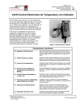
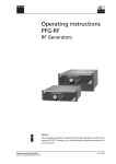
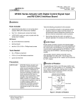
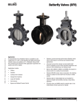
M9220-GGx-3
Proportional Electric Spring Return Actuators
Part No. 34-636-1697, Rev. B
Installation Instructions
Issued February 4, 2009
Supersedes June 20, 2006
Applications
Installation
The M9220-GGx-3 Proportional Electric Actuators are
direct-mount, spring return electric actuators that
operate on AC/DC 24V power. These bidirectional
actuators do not require a damper linkage, and are
easily installed on dampers with 1/2 to 3/4 in. or 12 to
19 mm round shafts, or 3/8 and 1/2 in. or
10, 12, and 14 mm square shafts using the standard
shaft clamp included with the actuator. An optional
M9220-600 Jackshaft Coupler Kit is available for
3/4 to 1-1/16 in. or 19 to 27 mm round shafts, or
5/8 and 3/4 in. or 16, 18, and 19 mm square shafts.
The M9220-GGx-3 Proportional Electric Spring Return
Actuators mount directly to the surface in any
convenient orientation using two M3 x 9.5 mm
self-drilling sheet metal screws and the anti-rotation
bracket (parts included with the actuator). No additional
linkages or couplers are required. Electrical
connections are color-coded and identified with
numbers permanently marked on the actuator cable.
A tag on the actuator cable identifies the electrical
connections, and wiring details are also included on the
actuator housing.
A single M9220-GGx-3 Series Proportional Electric
Spring Return Actuator provides a running and spring
return torque of 177 lb·in (20 N·m). Two or three like
models mounted in tandem deliver twice or triple the
torque (354 lb·in [40 N·m] or 531 lb·in [60 N·m]).
Integral line voltage auxiliary switches are available on
the GGC models to indicate end-stop position or to
perform switching functions within the selected rotation
range.
IMPORTANT: Do not install or use this
M9220 GGx-3 Proportional Electric Spring Return
Actuator in or near environments where corrosive
substances or vapors could be present. Exposure of
the electric actuator to corrosive environments may
damage the internal components of the device, and
will void the warranty.
IMPORTANT: Use this M9220-GGx-3 Proportional
Electric Spring Return Actuator only to control
equipment under normal operating conditions.
Where failure or malfunction of the electric actuator
could lead to personal injury or property damage to
the controlled equipment or other property,
additional precautions must be designed into the
control system. Incorporate and maintain other
devices such as supervisory or alarm systems or
safety or limit controls intended to warn of, or protect
against, failure or malfunction of the electric
actuator.
Parts Included
•
proportional electric spring return actuator with
coupler
•
anti-rotation bracket
•
manual override crank
•
two M3 x 9.5 mm self-drilling sheet metal mounting
screws
•
two No. 10-32 x 9/16 in. thread-forming conduit
screws
Special Tools Needed
•
torque wrench with 3/8 in. (10 mm) socket
•
digital voltmeter or M9000-200 Commissioning
Tool
•
flat blade screwdriver
M9220-GGx-3 Proportional Electric Spring Return Actuators Installation Instructions
1
Dimensions
4
(102)
2
(51)
1-19/32
(40)
1-19/32
(40)
3-3/16
(81)
1/8
(3)
3/4
(19)
A
2-3/16
(56)
1-19/32
(40)
1-1/16
(27)
10-5/16
(262)
10
(254)
6-15/16
(176)
1/4 (6.5)
Mounting Hole
(6 Locations)
1
(25)
2-3/16
(56)
FIG:M9210_9220_dimen
1-3/4
(44)
Figure 1: M9220-GGx-3 Proportional Electric Spring Return Actuator Dimensions, in. (mm)
2
M9220-GGx-3 Proportional Electric Spring Return Actuators Installation Instructions
Accessories
Table 1: Accessories and Replacement Parts (Order Separately)
Code Number
Description
DMPR-KC0031
7 in. (178 mm) Blade Pin Extension (without Bracket) for Johnson Controls Direct-Mount Damper
Applications
M9000-200
Commissioning Tool that Provides a Control Signal to Drive 24 V On/Off, Floating, Proportional,
and/or Resistive Electric Actuators
M9000-153
Crank arm
M9000-158
Tandem Mounting Kit used to Mount Two Models of M9210/20 Proportional Electric Spring Return
Actuators
M9000-170
Remote Mounting Kit, Horizontal. Kit includes Mounting Bracket, M9000-153 Crank Arm, Ball Joint,
and Mounting Bolts
M9000-171
Remote Mounting Kit, Vertical. Kit includes Mounting Bracket, M9000-153 Crank Arm, Ball Joint, and
Mounting Bolts
M9000-320
Weather Shield Enclosure - NEMA 3R enclosure for protecting a single M9210/20 from rain, sleet, or
snow.
M9000-604
Replacement Anti-rotation Bracket Kit (with Screws) for M9210-xxx-3 Series Proportional Electric
Spring Return Actuators
M9220-600
1 in. (25 mm) Jackshaft Coupler Kit (with Locking Clip) for Mounting M9210-xxx-3 Series Proportional
Electric Spring Return Actuators on Dampers with 3/4 to 1-1/16 in. or 19 to 27 mm Round Shafts, or
5/8 and 3/4 in. or 16, 18, and 19 mm Square Shafts
M9220-601
Replacement Coupler Kit (with Locking Clip) for Mounting M9210-xxx-3 Series Proportional Electric
Spring Return Actuators on Dampers with 1/2 to 3/4 in. or 12 to 19 mm Round Shafts, or 3/8 and 1/
2 in. or 10, 12, and 14 mm Square Shafts
M9220-602
Replacement Locking Clips for M9210-xxx-3 Series Proportional Electric Spring Return Actuators
(Five per Bag)
M9220-603
Adjustable Stop Kit for M9210-xxx-3 Series Proportional Electric Spring Return Actuators
M9220-604
Replacement Manual Override Cranks for M9210-xxx-3 Series Proportional Electric Spring Return
Actuators (Five per Bag)
M9220-610
Replacement Shaft Gripper, 10 mm Square Shaft with Locking Clip
M9220-612
Replacement Shaft Gripper, 12 mm Square Shaft with Locking Clip
M9220-614
Replacement Shaft Gripper, 14 mm Square Shaft with Locking Clip
1.
Furnished with the damper and may be ordered separately.
Mounting
The M9220-GGx-3 Proportional Electric Spring Return
Actuators can be easily installed on dampers with 1/
2 to 3/4 in. or 12 to 19 mm round shafts, or 3/8 and 1/
2 in. or 10, 12, and 14 mm square shafts. An M9220600 Jackshaft Coupler Kit is available for 3/4 to 11/
16 in. or 19 to 27 mm round shafts, or 5/8 and 3/4 in. or
16, 18, and 19 mm square shafts; see Table 1 for more
details. If the damper shaft extends less than 3-19/32
in. (91 mm), see the Removable Coupler section for
further instructions. If the damper shaft extends less
than 1-5/32 in. (29 mm), install an extension
recommended by the damper manufacturer.
M9220-GGx-3 Proportional Electric Spring Return Actuators Installation Instructions
3
Counterclockwise (CCW) Spring Return
Direction – Clockwise (CW) Powered
Operation
For CCW spring return direction, mount the actuator to
the damper shaft so that Side A of the actuator is away
from the damper as illustrated in Figure 2. With power
applied, the actuator drives CW from the 0° position,
and spring returns CCW.
Removable Coupler
The coupler may be installed on either side of the
output hub. If the damper shaft is less than 3-19/32 in.
(91 mm) long, insert the coupler in the face of the
actuator closest to the damper. If the damper shaft is
shorter than 1-5/32 in. (29 mm) long, a shaft extension
is required to mount the actuator.
U-Bolt Nut
and Washer
(Qty Two)
Side A: CCW Spring Return Direction
A
Shaft Coupler
Auxiliary Switch
Adjuster Located
on the Right
80
90
Pointer Showing
Actuator in the
Spring Return
Position
10
70
60
50
40
30
20
Pointer
-5
U-Bolt
Locking Clip
Assembled View
of Coupler
Subassembly
FIG:sidea
FIG:chpos
Manual
Override
Figure 4: Changing the Position of the Coupler
Figure 2: Side A of Actuator
Clockwise (CW) Spring Return Direction –
Counterclockwise (CCW) Powered Operation
To change the spring return direction to CW, mount the
actuator to the damper shaft so that Side B of the
actuator is away from the damper as illustrated in
Figure 3. With power applied, the actuator now drives
CCW from the 0° position, and spring returns CW.
Side B: CW Spring Return Direction
B
Auxiliary Switch
Adjuster Located
on the Left
Pointer Showing
Actuator in the
Spring Return
Position
10
-5
30
40
50
60
70
1. Mount the coupler on either Side A or Side B of the
actuator, as determined by the shaft length.
2. Snap the locking clip securely into the coupler
retention groove to retain the coupler.
Manual Override
Use only the supplied manual override crank to
reposition the actuator hub when using the manual
override feature.
IMPORTANT: Applying excessive torque to the
manual override or running the manual override with
a power tool may damage the internal components
of the actuator and cause premature failure.
80
20
To change the position of the coupler, see Figure 4 and
proceed as follows:
90
To reposition the actuator hub, proceed as follows:
1. De-energize the actuator.
2. Insert the hex end of the manual override crank
into the manual override adjustment point on the
face of the actuator.
FIG:sideb
Manual
Override
3. Rotate the manual override crank in the direction
indicated by the arrow on the label.
Figure 3: Side B of Actuator
4
M9220-GGx-3 Proportional Electric Spring Return Actuators Installation Instructions
Note: The actuator requires 27 rotations of the
manual override crank from the fully spring return
position to fully reposition the actuator hub. At the
end of travel, the rotational resistance increases;
do not force the actuator hub past this point.
2. Bend or cut the anti-rotation bracket to fit the
damper frame or duct as illustrated in Figure 6.
Note: You can bend the anti-rotation bracket to fit
a round damper.
Anti-rotation Bracket
4. Rotate the manual override crank a half turn in the
opposite direction to lock the actuator hub in place.
Note: To unlock the actuator hub, rotate the
manual override crank in the direction indicated by
the arrow on the label. The actuator hub
automatically unlocks when power is applied to the
actuator, and returns the actuator to normal drive
and spring return operation.
Mounting the Actuator
To mount the actuator, proceed as follows:
1. See the dimensions in Figure 5 and Table 2 to
ensure the correct positioning of the anti-rotation
bracket.
A
Slot for Mounting the
Anti-rotation Bracket
Anti-rotation Bracket
Actuator Shown with Anti-rotation Bracket
Assembled to Both the Top and Bottom
Anti-rotation Slots
M3 x 9.5 mm
Self-Drilling
Sheet Metal Screws
(Two Locations)
A
Dimension
B
Dimension
A
Damper Frame
FIG:brfit
Anti-rotation Bracket
FIG:brpos
Figure 6: Fitting the Anti-Rotation Bracket on the
Damper Frame or Duct
Figure 5: Positioning the Anti-Rotation Bracket
Table 2: Dimensions from Anti-rotation Bracket to
Shaft Center
Shaft Diameter
Dimension A,
in. (mm)
Dimension B,
in. (mm)
1/2 to 9/16 in.
(12 to 14 mm)
8-9/32
(210)
7
(178)
5/8 to 3/4 in.
(16 to 19 mm)
8-5/32
(207)
6-29/32
(175)
IMPORTANT: The tab on the anti-rotation bracket
must fit midpoint in the actuator slot. Positioning the
tab midpoint in the slot prevents actuator binding
and premature wear, and makes actuator removal
easier.
3. Drill mounting holes in the damper frame or duct
using the anti-rotation bracket as a guide (based
on the measurements obtained in Table 2 and
Figure 5).
4. Secure the anti-rotation bracket to the damper
frame or duct using the two M3 x 9.5 mm
self-drilling sheet metal screws provided and a
1/4 in. (6 mm) blade screwdriver or 5/16 in. (8 mm)
nut driver.
IMPORTANT: Do not overtighten the mounting
screws to avoid stripping the threads. Be certain that
the tab on the anti-rotation bracket remains properly
positioned in the slot on the actuator, and that the
actuator remains parallel to the mounting surface.
5. Slide the actuator onto the damper shaft, and
position the tab of the anti-rotation bracket into the
slot at the bottom of the actuator as illustrated in
Figure 6.
M9220-GGx-3 Proportional Electric Spring Return Actuators Installation Instructions
5
7. Evenly hand tighten each clamp nut onto the
U-bolt, keeping the actuator flat. Secure the U-bolt
to the damper shaft and tighten to a torque of 100
to 125 lb·in (11 to 14 N·m).
8. To release the spring, turn the manual override
crank in the direction indicated on the label; the
actuator spring returns to its starting position. If this
step is omitted, the spring releases automatically
when power is applied to the actuator.
9. Remove the manual override crank and store it in
an unused mounting hole.
10. Apply power long enough for the actuator to travel
a full stroke, and verify that the actuator rotates
freely throughout the range.
2. Determine the desired rotation range. If a 65 to
90° rotation range is desired, add one stroke
limiting stop. If a 35 to 60° rotation range is desired,
add two stroke limiting stops.
Note: If two stroke limiting stops are applied, use
the manual override crank to position and lock the
actuator in a mid-stroke position to gain access to
both stroke limiting stop mounting positions.
3. Mount the stroke limiting stops in the desired
position using the two M4 x 10 mm self-tapping
screws provided. Tighten the screws to a torque of
35 lb·in (4 N·m).
4. Manually reposition the coupler so that the coupler
set screw aligns with the nodule guide that
corresponds to the value determined in Step 2.
Example:
For a rotation range of 65°, mount one stroke
limiting stop in the minimum stroke position as
illustrated in Figure 8.
A
Note: If electric power is not available, complete
this verification by reinserting the manual override
crank and turning it in the direction indicated to
rotate the coupler to the fully open position.
Rotation Range Using Optional
M9220-603 Adjustable Stop Kit
Stroke Limiting
Stop (Qty Two)
Lock Screw
(Qty Two)
Adjustment Holes
(Qty Two Groups
of Eight)
80
90
The actuator is factory set for 90° rotation, and its
rotation range is limited in 5° increments to a minimum
of 30°. Stroke limiting stops are attached in the field to
the shaft coupler side of the actuator to reduce the
rotation range. Attaching a stroke limiting stop in the
furthest mounting position reduces the rotation range of
the actuator by 5°. Each progressive mounting position
reduces the rotation range an additional 5°.
10
70
60
50
40
30
20
-5
Shaft Position
Pointer
Sweep Angle
Indicated in 5°
Increments
Figure 8: One Stroke Limiting Stop
Mounted in the Minimum Stroke Position for a
Rotation Range of 65°
FIG:dampos
1. Check that the damper blade is accessible or that
its position is permanently marked on the end of
the damper shaft as illustrated in Figure 7.
Figure 7: Damper Position Icons
6
FIG:range65
6. Rotate the damper blades to the desired position if
the power is lost. To ensure a tight seal, insert the
manual override crank and turn it in the direction
indicated by the arrow on the label five turns; the
position indicator should be near the 0° position on
the scale. Quickly rotate the manual override crank
a half turn in the opposite direction to temporarily
lock the actuator hub in place.
M9220-GGx-3 Proportional Electric Spring Return Actuators Installation Instructions
Wiring
Once the actuator reaches the commanded position, it
holds that position until power is removed. If power is
removed, the actuator spring returns to its
-5° position (unless an external mechanical limit is
reached). A stall condition while driving between
-5 to 90° causes the output hub to stop motion and
hold its position until power is removed. Rotation is
mechanically limited to the -5 and 90° positions by
integral end-stops. Optional end-stops are available to
limit the output hub travel. An anti-rotation bracket
prevents rotational movement of the actuator body.
S1
S2
21
22
24
23
24
21
BLK/ BLK/ BLK/ WHT/ WHT/ WHT/
RED BLU GRY RED BLU GRY
21
24
22
25
23
26
COM
NO COM
NC
!
NC
NO
Figure 9: Auxiliary Switch Wiring Diagram for
GGC Models
DC 0(2)...10V Control
BLK RED GRY ORN
3
4
1
2
See Figure 9 and Figure 10 for proper wiring of the
M9220-GGx-3 Proportional Electric Spring Return
Actuator.
CAUTION: Risk of Electric Shock.
Disconnect the power supply before
making electrical connections to avoid
electric shock.
25
26
FIG:auxswtch
The M9220-GGx-3 Proportional Electric Spring Return
Actuator provides reliable, integrated damper control.
An AC 24 V at 50/60 Hz or DC 24 V input signal
between the black and red wires, and a
DC 0(2) to 10 V input control signal, causes the output
hub to rotate from -5 to 90° (unless an external
mechanical limit is reached).
AC/DC
24 V
~(+)
DC 0(2)...10 V
+
Y
+
DC 0(2)...10 V
U
COM
IMPORTANT: Make all wiring connections in
accordance with local, national, and regional
regulations. Do not exceed the electrical ratings of
the M9220-GGx-3 Proportional Electric Spring
Return Actuator.
0(4)...20mA Control with
External Resistor
BLK RED GRY ORN
3
4
1
2
AC/DC
24 V
~(+)
+
0(4)...20mA
Y
500Ω / 0.25 W
+
DC 0(2)...10 V
U
COM
wiring
!
CAUTION: Risk of Property Damage.
Do not apply power to the system before
checking all wiring connections. Short
circuited or improperly connected wires
may result in permanent damage to the
equipment.
Figure 10: Control Wiring Diagrams
M9220-GGx-3 Proportional Electric Spring Return Actuators Installation Instructions
7
Setup and Adjustments
Mode Selector Switch and CAL Function
Direction of Action
The M9220-GGx-3 Proportional Electric Spring Return
Actuators are factory set at Direct Acting (DA), DC 0 to
10 V control input (Figure 12). To change to RA
operation, move the mode selection switch from DA to
RA. The DC input signal is selectable from
DC 0 to 10 V or from DC 2 to 10 V, which corresponds
to 0 to 95° rotation. If the rotation range is reduced, the
end-stop is reached with a reduced input signal. For
example, if a DC 0 to 10 V input signal is selected and
the rotation range is limited to 75°, the end-stop is
reached at DC 8.3 V. If an external 500 ohm resistor is
placed across the input (see Figure 10), the switch
positions then select between 0-20 mA or 4-20 mA.
CAL
B
2-10
+
DA
0-10
Control Inputs
CCW Face
of Actuator
CW Face
of Actuator
RA
RA
+
2-10
RA
RA
0-10
Side A of Actuator
0-10
2-10
+
0-10
Side B of Actuator
DA
Figure 12: Mode Selection
Mode Selection
Switch Setting
DA
CAL
2-10
+
A
modesel
The M9220-GGx-3 Proportional Electric Spring Return
Actuators are factory set for Direct Acting (DA)
operation. In DA mode, applying an increasing input
signal to the control input drives the actuator away from
the spring return position. Reverse Acting (RA)
operation is also available. In RA mode, applying an
increasing input signal to the control input drives the
actuator toward the spring return position. Figure 11
and Figure 12 indicate how the drive direction for the
actuator depends on the spring return direction and the
position of the mode selection switch.
DA
The CAL function enables the actuator to redefine the
selected control input range proportionally across a
reduced rotation range. The actuator stores the
reduced rotation range in nonvolatile memory (retains
data when power is lost or removed).
Increasing Signal
Decreasing Signal
Rotation Position
Direction Feedback
Direct
Acting
0-10V
0.0V 1.7V 3.3V 5.0V 6.7V 8.3V 10.0V
2-10V
2.0V 3.3V 4.7V 6.0V 7.3V 8.7V 10.0V
Reverse
Acting
0-10V
10.0V 8.3V 6.7V 5.0V 3.3V 1.7V 0.0V
2-10V
10.0V 8.7V 7.3V 6.0V 4.7V 3.3V 2.0V
* 0° is the spring return position.
Figure 11: Nominal Feedback Signal Relative to
Rotation Position
FIG:DRVPOS
To calibrate the control input range, proceed as follows:
1. With power off, move the mode selection switch to
the CAL position (Figure 12). Then, energize the
actuator. The actuator automatically rotates until
the end-stops are found, and proportionally
reconfigures the control input range to the reduced
rotation range.
2. Return the mode selection switch to the desired
selection (example: DA, 0 to 10 VDC control input).
Note: During normal operation, if the actuator
stroke increases due to seal or seat wear, the input
is redefined to the increased rotation range in
approximately 0.5° increments.
3. If the actuator mounting position is changed or if
the linkage is adjusted, repeat Steps 1 and 2 to
reinitiate the CAL function.
Note: To repeat calibration with power applied, move
the mode selection switch out of the CAL position for at
least 2 seconds before returning it to the CAL position.
Auto calibration begins 5 seconds after you return it to
the CAL position.
8
M9220-GGx-3 Proportional Electric Spring Return Actuators Installation Instructions
The tandem configuration (Figure 13 and Figure 15)
provides twice (with two actuators) or triple (with three
actuators) the running and spring return torque of a
single actuator, or 354 lb·in (40 N·m), 531 lb·in
(60 N·m). The actuators may be mounted in tandem
using the M9000-158 Tandem Mounting Kit. To mount
a third actuator, user-configured bracketing is
required..
•
Two or three M9220-GGx-3 actuators may be
operated in tandem on the same shaft. If mounting
two actuators, see Figure 13; for three actuators,
see Figure 15.
•
Each actuator requires separate 24 volt power.
When two or more actuators connected in tandem
share a common power source, the total maximum
power draw is actually 1.5 times the normal
running current for each actuator.
(Total Power = Number of Actuators x Running
Power x 1.5).
•
Only one of the actuators can be configured as the
master. Set the selector switch to the master
position (Figure 14).
DC 0(2)...10V Control with Tandem Connection
Master
(M9220GGx actuator)
Slave
(M9220GGx actuator only)
BLK RED GRY ORN
4
1
3
2
BLK RED GRY ORN
1
3
4
2
+
+
Side A of Actuator
Side B of Actuator
select
Tandem Operation: GGx Master with
GGx Slaves
Figure 14: Tandem Selector Switch
~(+)
DC 0(2)...10 V
Y
•
The other GGx actuator(s) must be configured as
slave(s), by setting the tandem selector switch to
the slave position.
•
The master can accept DC 0-10 V or DC 2-10 V, or
4-20 mA command signals based on the master’s
switch settings and/or external resistor.
•
The master and slave(s) must have matching
RA/DA settings..
+
DC 0(2)...10 V
U
COM
FIG:tandem1
AC/DC
24 v
Figure 13: Tandem Connection
Follow these guidelines for tandem operation:
DC 0(2)...10V Control with Multiple Slaves
Master
(M9220GGx actuator)
BLK RED GRY ORN
3
4
1
2
+
Slave
(M9220GGx actuator only)
BLK RED GRY ORN
3
4
1
2
BLK RED GRY ORN
3
4
1
2
+
+
~(+)
DC 0(2)...10 V
Y
+
DC 0(2)...10 V
U
COM
FIG:tand2
AC/DC
24 V
Slave
(M9220GGx actuator only)
Figure 15: Tandem Connection with Three Actuators
M9220-GGx-3 Proportional Electric Spring Return Actuators Installation Instructions
9
•
The master and slave(s) must spring return in the
same direction.
•
Once tandem-operating actuators are mounted to
a damper shaft, manual override is no longer an
available function.
The feedback wire of the master (orange) is connected
to the command wire(s) of the slave(s)(gray). As the
master moves response to position commands, the
master sets its feedback wire to 0 volts if moving
counterclockwise, 5 volts if holding, or 10 volts if
moving clockwise.
Each slave actuator must have its tandem selector
switch (Figure 14) set on the slave setting. Its gray
command wire must be connected the master’s orange
feedback wire.
Position information, 0-10 (or 2-10) volts, is available
on the slave actuator’s feedback wire (orange).
The switch point of Auxiliary Switch No. 1 is fixed. The
switch point of Auxiliary Switch No. 2 is independently
and continuously adjustable from 25 to 95°. See
Figure 16 and use the method in the following example
for the most accurate positioning of Auxiliary Switch
No. 2.
To change the switch point of Auxiliary Switch No. 2,
proceed as follows:
1. Position the actuator in the full spring return
position.
Note: Auxiliary Switch No. 2 is factory set to trip
when the actuator reaches the 81° position.
2. Rotate the switch adjuster until it points to the
desired switch point.
A
Switch
Adjuster
The GGC models include two integral auxiliary
switches with a switch adjuster accessible on either
face of the actuator (as illustrated in Figure 2 and
Figure 3). The nominal factory setting for Auxiliary
Switch No. 1 is 11° closing, and the nominal factory
setting for Auxiliary Switch No. 2 is 81° opening
(relative to a 0 to 90° rotation range). See the Technical
Specifications table for the auxiliary switch ratings.
!
10
WARNING: Risk of Electric Shock.
Disconnect each of multiple power
supplies before making electrical
connections. More than one disconnect
may be required to completely
de-energize equipment. Contact with
components carrying hazardous voltage
can cause electric shock and may result
in severe personal injury or death.
FIG:swpnt
Auxiliary Switches (GGC Model Only)
Figure 16: Switch Point Settings
3. Connect Auxiliary Switch No. 2 to a power source
or an ohmmeter, and apply power to the actuator.
The actuator moves to the fully open position and
holds while power is applied.
4. Observe the switch point. If required, repeat
Steps 2 and 3.
Repairs and Replacement
A number of replacement parts are available; see
Table 1 for more details. If the M9220-GGx-3
Proportional Electric Spring Return Actuator fails to
operate within its specifications, replace the unit. For a
replacement electric actuator, contact the nearest
Johnson Controls® representative.
M9220-GGx-3 Proportional Electric Spring Return Actuators Installation Instructions
Technical Specifications
M9220-GGx Proportional Electric Spring Return Actuators (Part 1 of 2)
Power Requirements
AC 24 V (AC 19.2 to 30 V) at 50/60 Hz: Class 2 (North America) or SELV
(Europe), 15.5 VA Running, 7.7 VA Holding Position;
DC 24 V (DC 21.6 to 24.4 V): Class 2 (North America) or SELV
(Europe), 6.7 W Running, 2.9 W Holding Position
Transformer Sizing
Requirements
20VA Minimum per Actuator
Input Signal/Adjustment
Factory Set at DC 0 to 10 V, CW Rotation with Signal Increase;
Selectable DC 0 (2) to 10 V or 0 (4) to 20 mA with Field Furnished
500 ohm, 0.25 W minimum resistor;
Switch Selectable Direct or Reverse Action with Signal Increase
Control Input Impedance
Voltage Input: 200,000 ohms;
Current Input: 500 ohms with Field Furnished 500 ohm Resistor
Feedback Signal
DC 0 (2) to 10 V for Desired Rotation Range up to 90°;
Corresponds to Rotation Limits, 1 mA Maximum
Auxiliary Switch Rating
GGC Models
Two Single-Pole, Double-Throw (SPDT), Double-Insulated Switches with
Gold Flash Contacts:
AC 24 V, 50 VA Pilot Duty;
AC 120 V, 5.8 A Resistive, 1/4 hp, 275 VA Pilot Duty;
AC 240 V, 5.0 A Resistive, 1/4 hp, 275 VA Pilot Duty
Spring Return
Direction is Selectable with Mounting Position of Actuator:
Side A, Actuator Face Away from Damper for CCW Spring Return;
Side B, Actuator Face Away from Damper for CW Spring Return
Running and Spring Return
Torque
177 lb·in (20 N·m) for a Single Actuator;
354 lb·in (40 N·m) for Two Like Models Mounted in Tandem
531 lb·in (60 N·m) for Three Like Models Mounted in Tandem
Rotation Range
Adjustable from 30 to 90° CW or CCW with Optional
M9220-603 Adjustable Stop Kit; Mechanically Limited to 90°
Rotation Time
Power On
(Running)
150 Seconds for 0 to 177 lb·in (0 to 20 N·m) at All Operating Conditions;
Independent of Load
Power Off
(Spring
Returning)
11 to 15 Seconds for 0 to 177 lb·in (0 to 20 N·m) at Room Temperature;
35 Seconds Maximum for 0 to 177 lb·in (0 to 20 N·m) at -22°F (-30°C)
130 Seconds Maximum for 0 to 177 lb·in (0 to 20 N·m) at -40°F (-40°C)
Cycles
Audible Noise Rating
Electrical Connections
Conduit Connections
60,000 Full Stroke Cycles; 1,500,000 Repositions
Power On
(Running)
<45 dBA at 39-13/32 in. (1 m)
Power On
(Holding)
<20 dBA at 39-13/32 in. (1 m)
Power Off
(Spring
Returning)
<55 dBA at 39-13/32 in. (1 m)
Actuator
(All Models)
48 in. (1.2 m) Halogen-Free Cable with 18 AWG (0.75 mm2) Wire Leads
Auxiliary
Switches
(GGC Models)
48 in. (1.2 m) Halogen-Free Cable with 18 AWG (0.75 mm2) Wire Leads
Integral Connectors for 3/8 in. (10 mm) Flexible Metal Conduit
M9220-GGx-3 Proportional Electric Spring Return Actuators Installation Instructions
11
M9220-GGx Proportional Electric Spring Return Actuators (Part 2 of 2)
Mechanical Connections
Standard
Shaft Clamp
Included with
Actuator
1/2 to 3/4 in. or 12 to 19 mm Diameter Round Shafts, or
3/8 and 1/2 in. or 10, 12, and 14 mm Square Shafts
Optional
M9220-600
Jackshaft
Coupler Kit
3/4 to 1-1/16 in. or 19 to 27 mm Diameter Round Shafts, or
5/8 and 3/4 in. or 16, 18, and 19 mm Square Shafts
Aluminum Enclosure
Ambient Conditions
NEMA 2 (IP54) for All Mounting Orientations
Operating
-40 to 131°F (-40 to 55°C); 90% RH Maximum, Noncondensing
Storage
-85 to 185°F (-65 to 85°C); 95% RH Maximum, Noncondensing
Dimensions
Compliance
See Figure 1.
United States
UL Listed, CCN XAPX, File E27734; to E60730-1A: 2003-08, Ed. 3.1,
Automatic Electrical Controls for Household and Similar Use; and UL
60730-2-14: 2002-02, Ed. 1, Part 2, Particular Requirements for Electric
Actuators.
Canada
UL Listed, CCN XAPX7, File E27734; to E60730-1:02-CAN/CSA: July
2002, 3rd Ed., Automatic Electrical Controls for Household and Similar
Use.
Europe
CE Mark, EMC Directive 89/336/EEC (All Models)
CE Mark, Low Voltage Directive 73/23/EEC(M9220-GGC-3 Model)
Australia and
New Zealand
Shipping Weight
C-Tick Mark, Australia/NZ Emissions Compliant (All Models)
6.4 lb (2.9 kg)
The performance specifications are nominal and conform to acceptable industry standards. For application at conditions beyond these
specifications, consult the local Johnson Controls office. Johnson Controls, Inc. shall not be liable for damages resulting from misapplication or
misuse of its products.
Building Efficiency
507 E. Michigan Street, Milwaukee, WI 53202
Metasys® and Johnson Controls® are registered trademarks of Johnson Controls, Inc.
All other marks herein are the marks of their respective owners. © 2009 Johnson Controls, Inc.
12
M9220-GGx-3 Proportional Electric Spring Return Actuators Installation Instructions
Published in U.S.A.
www.johnsoncontrols.com